

Page 1
Weidmuller Ltd.
10 Spy Court
Markham, ON L3R 5H6
Tel: (905)475-1507
Fax: (905)475-5855
Weidmuller Ltd
821 Southlake Blvd.
Richmond, VA 23236 U.S.A.
Tel: (804)794-2877
Fax: (804)794-0252
ISO 9001 Registered
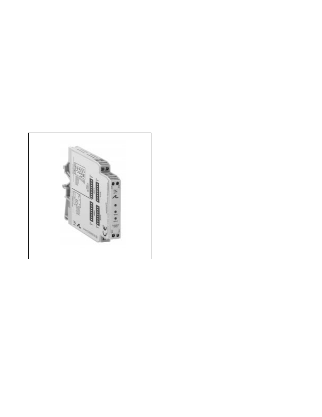
Electronic Interface Modules
G468 Ultra SlimPak®
AC Input, Field Configurable Isolator
• field configurable via DIP switches for different inputoutput combinations
• provides an isolated DC output in proportional to an
AC input
• field configurable input ranges 100mV to 250Vac or
10mA to 100mAac
• flexible power supply accepts 9 to 30Vdc
• 5 field configurable output ranges 0-5V, 0-10V,
0-1mA, 0-20mA, 4-20mA
• CSA approved, UL recognized, CE marked
Page 2
Description
Application
Diagnostic LED
The field configurable G468 is a DIN rail mount, AC input signal conditioner with 1800Vdc isolation between
input, output and power. The field configurable input and output offers flexible, wide ranging capability for
scaling, converting or buffering AC inputs ranging from 5mA to 100mAac or 50mV to 250Vac.
For current inputs above 100mAac, it is recommended that an input shunt resistor be used and the G468
be configured for the proper input range. For example, a 5Aac current transformer output can use the
Action model C006 shunt resistor (0.1M, 5M) and set the input of the G468 for 0-500mVac.
The DC output of the G468 is proportional to the average of the fully-rectified AC input signal, and is
calibrated for sine waves between 40-400Hz.
The Ultra SlimPak G468 is useful in applications requiring an isolated, conditioned DC output from an AC
signal. Typical applications include energy management, load shedding, motor current/load monitoring,
locked rotor detection, isolation and data acquisition. The output of the G468 can drive a digital meter for
direct display or can interface with alarm or control devices including PLCs and computers.
The G468 is equipped with a dual function LED signal monitor. The green, front-mounted LED indicates
both DC power and input signal status. Active DC power is indicated by an illuminated LED. If the input
signal is more than 110% of the full-scale range, the LED will quickly flash at 8Hz. If this continues to occur,
you may wish to change your full-scale input range setting.
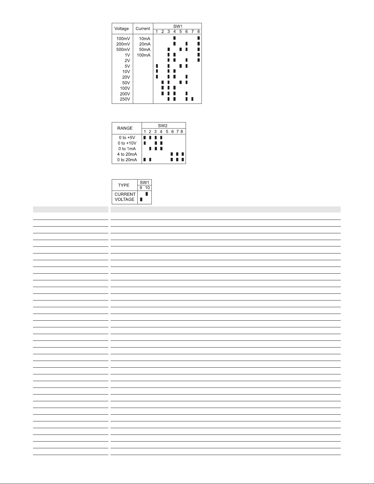
Table 1:
G468 input range
selector switch
settings
Table 2:
G468 output range
selector switch
settings
Table 3:
G468 input type
settings
Page 3

Major advantages of the G468 are its wide ranging capability and ease of configuration. The G468 has 15
input range switch settings. Trim potentiometers allow 50% input zero and span adjustablity within each of
the 15 full-scale, input ranges.
For example, the 200V switch setting in Table 1 configures the input for a 0 to 200Vac range. Since the
span can be contracted by 50%, this enables an input span as narrow as 100Vac of the range. This span
can be positioned anywhere within the 0-200Vac range with a zero offset as large as 50% of the full scale
range (e.g. 100 to 200Vac range).
Unless otherwise specified, the factory presets the Model G468 as follows:
Input Range: 0-500mVac
Output: 4-20mA
The DC power input accepts any DC source between 9 and 30V, typically a 12V or 24Vdc source is used.
Do not attempt to change any switch settings with power applied. Severe damage will result!
Refer to Tables 1 through 3 for the proper switch settings. With power disconnected, use the switches (9 &
10) on SW1 to select the input type (voltage or current), on SW2 to select the desired output ranges, and
(1-8) on SW1 to select the desired input range.
1. After configuring the DIP switches, connect the input to a calibrated AC source. Connect the output of the
actual device load (or a load approximately equivalent to the actual device load value) and apply power.
Refer to the Terminal Wiring Diagram.
NOTE: to maximize thermal stability, final calibration should be performed in the operating installation,
allowing approximately 1 to 2 hours for warm up and thermal equilibrium of the system.
2. Set the calibrator to the desired minimum and adjust the zero potentiometer for the desired minimum
output.
3. Set the calibrator to the desired maximum and adjust the span potentiometer for the desired maximum
output.
4. Repeat steps 2 and 3, if necessary for best accuracy.
Configuration
WARNING
Calibration
Load
Firgure 2: Load monitoring using a current
transformer and the G468
Neu
Current Xfmr
(5A) 0 - 5A Output, typical
0-500mV
C006
0.1 ohm shunt
Hot
G468
ULTRA SLIM PAK
EG8
Page 4

Rated data
Input
Range
Impedance
Maximum ratings / type of protection
Field device excitation
Other input specification
Other input specification
Output
Range
Load
Burnout level
Zero / Span adjustment
Protection
Other output specification
Other output specification
Supply
Range
Consumption
Other supply specification
General
Accuracy
Linearity
Temperature coefficient (drift)
Transmission frequency
Response time. 90% span
Other general specification
Status LED
Isolation (# of ports)
Operating / Storage temperature
Housing (mounting)
Dimensions (L x W x H)
Wire range (conductor size)
Insulation stripping length
Tightening torque
Approvals
Ordering data
Ultra SlimPak
Heat sink (width)
Shunt resistor
AC current or voltage (40 to 400Hz)
0-10mAac to 0-100mAac or 0-100mVac to 0-250Vac, DIP switch selectable
20M for current, >100kM for voltage
200mAac, 60Vpeak for current, 300Vac for voltage
DC current or voltage
0-1mA, 0-20mA, 4-20mA, 0-5Vdc or 0-10Vdc, DIP switch selectable
<7.5kM (0-1mA), <600M (0/4-20mA), >500M (0-5V), >1000M (0-10V)
0 to 50% of full scale input / 50 to 100% of full scale input
DC voltage
9 to 30Vdc, inverter isolated
1.5W typ., 2.5W max. (200mA inrush at 9Vdc)
±0.1% of full scale typ., 0.5% max.
included in accuracy
±0.025% of full scale/°C typical
<250mS typical
input green (>110% of input: 8Hz)
1800V (3 port) between input, output and power
0 to 55°C / -25 to 70°C
EG8 (TS32 and TS35)
90mm x 12.7mm x 112.7mm max.
22-12AWG (0.5-4.0mm2)
7mm
0.4-0.8Nm
CSA (file LR-42272), UL (file E99775, CE marked (EMC dir. 89/336/EEC, LV dir. 73/23/EEC))
Cat. No.
G468 (factory calibration: 0-500mVac In, 4-20mA Out)
HS01-A (1.6mm) (conditionally required depending on installation, see heat sink data)
C006 (0.1M, 1%, 5W for use with external current transformer)
Note: G468-000X where X is the revision level
Specifications subject to change without notice. 99990011 - 8/98 Printed in Canada
110.2
TS32 RAIL
88.5
105.2
TS35 RAIL
12.6
90.0
 Loading...