

Page 1

Weidmuller Ltd.
10 Spy Court
Markham, ON L3R 5H6
Tel: (905)475-1507
Fax: (905)475-5855
Weidmuller Ltd
821 Southlake Blvd.
Richmond, VA 23236 U.S.A.
Tel: (804)794-2877
Fax: (804)794-0252
ISO 9001 Registered
Electronic Interface Modules
G438 Ultra SlimPak®
Potentiometer Input, Field Configurable
Signal Conditioner
• field configurable via DIP switches for different inputoutput combinations
• provides a DC output in proportion to a potentiometer
input
• potentiometers from 100M to 100kM
• wide ranging zero and span with 80% adjustability
• 5 field configurable output ranges 0-5V, 0-10V,
0-1mA, 0-20mA, 4-20mA
• flexible power supply accepts 9 to 30Vdc
• ASIC technology for high reliability
• CSA approved, UL recognized, CE marked
Page 2
Description The Ultra SlimPak G438 is a DIN rali mount, potentiometer input signal conditioner with 1800Vdc isolation
between DC power and the input/output circuitry. The input provides a constant voltage and is designed to
accept any three-wire potentiometer from 100M to 100KM. The field configurable output is switch selectable
providing either 0-5V, 0-10V, 0-1mA, 0-20mA or 4-20mA DC signal.
Wide ranging, precision zero and span pots, used in conjunction with DIP switches, allow 80% adjustability
of offset and gain to transmit a full scale output from any 20% portion of the potentiometer input.
The Ultra SlimPak G438 field configurable, potentiometer input signal conditioner is useful in transmitting
process control setpoints to remote PID controllers or interfacing position sensors to data acquisition and
control systems.
The G438's high density DIN rail mounting offers an extremely compact solution for saving valuable panel
space.
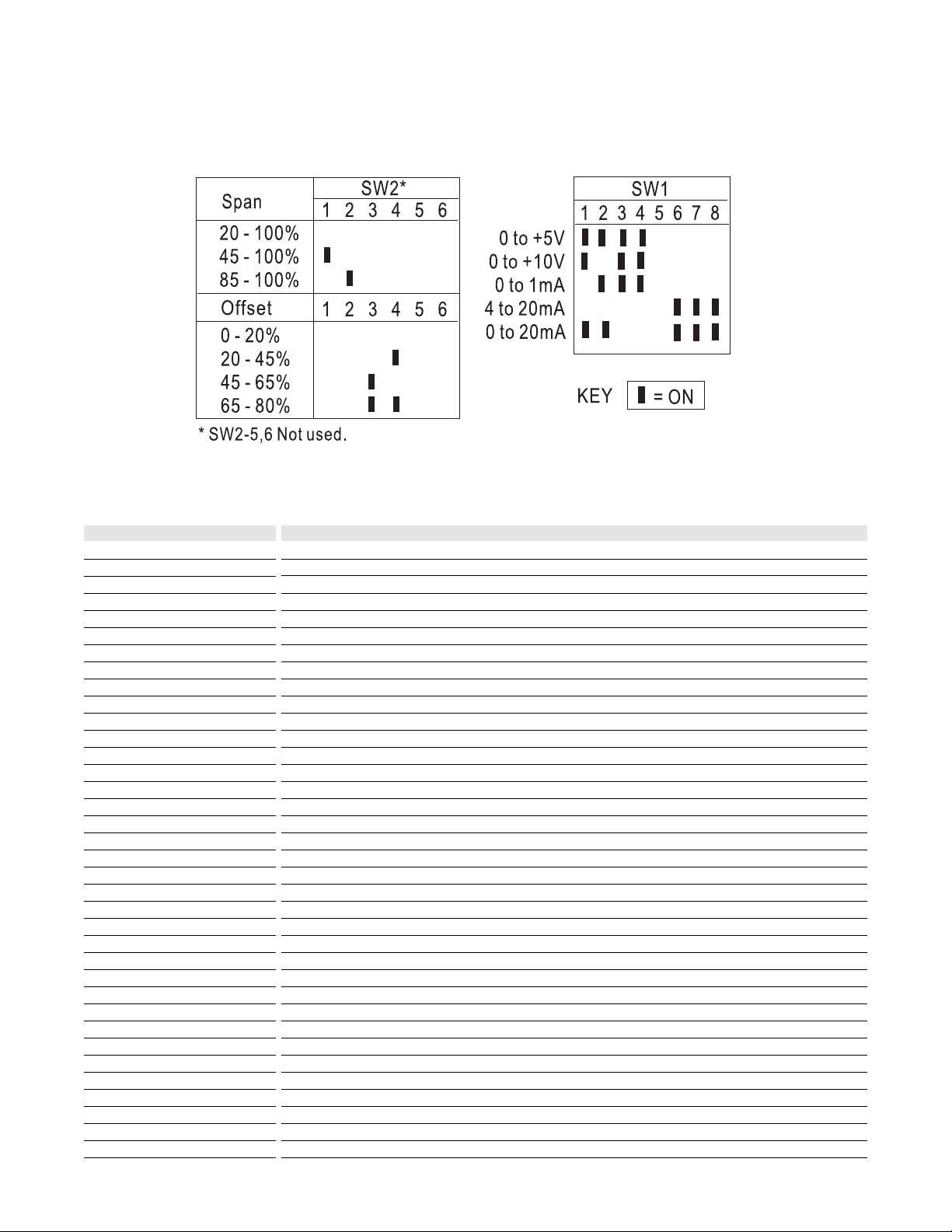
Table 1:
Input range switch selector (SW2)
Table 2:
Output range switch selector (SW1)
Page 3

A major advantage of the G438 is its wide ranging capabilities and ease of configuration.
For example, in a valve positioning application a potentiometer is sometimes used as a feedback signal.
Quite often a wide open valve is only a 25% turn of the feedback potentiometer. In this case the G438 can
easily be adjusted with the zero and span to provide a full scale output signal (e.g. 4-20mA) representing
0-25% or even 50-75% of the potentiometer input.
Unless otherwise specified, the factory presets the Model G438 as follows:
Input Range: 0 to 100%
Output: 4 to 20mA
The DC power input accepts any DC source between 9 and 30V; typically a 12V or 24Vdc source is used.
For other output ranges, refer to Tables 1 and 2 to reconfigure switches SW1 and SW2 for the desired input
and output ranges.
Do not attempt to change any switch settings with power applied. Severe damage will result!
1. With power disconnected, set the output and input switch selectors (SW1 and SW2) to the desired
ranges (Tables 1 and 2).
2. Connect the input and output as shown in wiring diagram. Connect the output to the actual device load
(or a load approximately equivalent to the actual device load value) and apply power.
NOTE: To maximize thermal stability, final calibration should be performed in the operating installation,
allowing approximately 1 to 2 hours for warm up and thermal equilibrium of the system.
3. Set the input potentiometer to the desired minimum and adjust the zero potentiometer for the desired
minimum output.
4. Set the input potentiometer to the desired maximum and adjust the span potentiometer for the desired
maximum output.
5. Repeat steps 3 and 4, if necessary, for best accuracy.
Configuration
WARNING
Calibration
Output (-)
52
Shield Ground
Potentiometer Input
(full counter clockwise)
DC Power (-)
22
12
42
52 51
42 41
INPUT
SPAN
ZERO
ULTRA
SLIMPAK
G438
12 11
22 21
51
Output (+)
41
Potentiometer Input
(wiper)
_
_
Potentiometer Input
11
(full clockwise)
21
DC Power (+)
Page 4

Rated data
Input
Range
Impedance
Maximum ratings / type of protection
Field device excitation
Other input specification
Other input specification
Output
Range
Load
Burnout level
Zero / Span adjustment
Protection
Other output specification
Other output specification
Supply
Range
Consumption
Other supply specification
General
Accuracy
Linearity
Temperature coefficient (drift)
Transmission frequency
Response time. 90% span
Other general specification
Status LED
Isolation (# of ports)
Operating / Storage temperature
Housing (mounting)
Dimensions (L x W x H)
Wire range (conductor size)
Insulation stripping length
Tightening torque
Approvals
Ordering data
Ultra SlimPak
Heat sink (width)
Shunt resistor
Potentiometer, 3 wire variable resistance
100M to 100kM, resistance end to end
1MegM minimum
500mV, 5mA maximum
DC current or voltage
0-1mA, 0-20mA, 4-20mA, 0-5Vdc or 0-10Vdc, DIP switch selectable
<7.5kM (0-1mA), <600M (0/4-20mA), >500M (0-5V), >1000M (0-10V)
0 to 80% of full scale input, DIP switch selectable / 20 to 100% of full scale input, DIP switch selectable
DC voltage
9 to 30Vdc, inverter isolated
1.5W typ., 2.5W max. (200mA inrush at 9Vdc)
±0.1% maximum at 25°C
included in accuracy
±0.05% of full scale/°C, max.
<200mS typical
power green (ON=OK)
1800V (2 port) between power and input/output (no isolation between input and output)
0°C to 55°C / -25°C to 70°C
EG8 (TS32 and TS35)
90mm x 12.7mm x 112.7mm max.
22-12AWG (0.5-4.0mm2)
7mm
0-4-0.8Nm
CSA (file LR-42272), UL (file E99775), CE marked (EMC dir. 89/336/EEC, LV dir. 73/23/EEC)
Cat.No.
G438 (factory calibration: 0-100% In, 4-20mA Out)
HS01-A (1.6mm) (conditionally required depending on installation, see heat sink data)
Note: G438-000X where X is the revision level
Specifications subject to change without notice. 99990013 - 8/98 Printed in Canada
12.6
110.2
TS32 RAIL
88.5
105.2
TS35 RAIL
90.0
 Loading...