

Page 1
ACT20X
Manual
Page 2

Page 3

Revision History
Version Date Change
0.0 02/2009 First Edition
1.0 12/2011 Further products
complemented
Contact Address
Weidmüller Interface GmbH & Co. KG
PO Box 3030
32720 Detmold
Klingenbergstraße 16
32758 Detmold
Germany
Phone +49 (0) 5231 14-0
Fax +49 (0) 5231 14-2083
E-Mail info@weidmueller.com
Internet www.weidmueller.com
1066540000/01/12.11 3
Page 4

Contents
Contents
Revision History ...............................................................................................................................................3
Contact Address...............................................................................................................................................3
Contents.............................................................................................................................4
1. Approvals...............................................................................................................7
1.1 CE........................................................................................................................................................7
1.2 EMC.....................................................................................................................................................7
1.3 ATEX...................................................................................................................................................7
1.4 IECEx..................................................................................................................................................7
1.5 cFMus.................................................................................................................................................7
1.6 UL........................................................................................................................................................7
1.7 GOST ..................................................................................................................................................7
1.8 DNV.....................................................................................................................................................7
2. Warranty Statement..............................................................................................8
2.1 36 Months Warranty..........................................................................................................................8
3. Safety Instructions................................................................................................9
3.1 Approved Use....................................................................................................................................9
3.2 Qualified Personnel...........................................................................................................................9
3.3 Accuracy of the Technical Documentation ....................................................................................9
3.4 Liability...............................................................................................................................................9
3.5 Definitions..........................................................................................................................................9
3.6 Symbol Identification......................................................................................................................10
3.7 Electrical Precautions.....................................................................................................................10
3.8 General Instructions .......................................................................................................................10
4. Introduction.........................................................................................................11
4.1 Product Description........................................................................................................................11
4.1.1 Family ACT20X.......................................................................................................................11
4.1.2 General Description ................................................................................................................13
4.1.3 The Six Basic Module Types in Detail ....................................................................................14
5. Installation........................................................................................................... 15
5.1 General.............................................................................................................................................15
5.1.1 Environment............................................................................................................................15
4
1066540000/01/12.11
Page 5

Contents
5.2 Unpacking........................................................................................................................................15
5.3 Mounting ..........................................................................................................................................16
5.4 Marking.............................................................................................................................................16
5.5 Electrical Connections ...................................................................................................................17
5.5.1 EMI Protection.........................................................................................................................17
5.6 Calibration and Adjustment ...........................................................................................................17
5.7 Release Lever..................................................................................................................................17
5.8 Encoding..........................................................................................................................................18
5.9 Configuration...................................................................................................................................19
6. Operation.............................................................................................................20
6.1 Normal Operation............................................................................................................................20
6.2 Warm-Up ..........................................................................................................................................20
6.3 Cleaning ...........................................................................................................................................20
7. Product Installation / Operation.........................................................................21
7.1 ACT20X-HDI-SDO (NAMUR Pulse Isolator) ..................................................................................21
7.1.1 Description ..............................................................................................................................21
7.1.2 Status/Alarm LEDs..................................................................................................................22
7.1.3 Electrical Connections ............................................................................................................23
7.1.4 Function Description ...............................................................................................................23
7.1.5 Specifications..........................................................................................................................23
7.2 ACT20X-HTI-SAO (Temperature/mA Converter)..........................................................................28
7.2.1 Description ..............................................................................................................................28
7.2.2 Status/Alarm LEDs..................................................................................................................29
7.2.3 Electrical Connections ............................................................................................................30
7.2.4 Specifications..........................................................................................................................30
7.3 ACT20X-SDI-HDO (Solenoid/Alarm Driver)...................................................................................37
7.3.1 Description ..............................................................................................................................37
7.3.2 Status/Alarm LEDs..................................................................................................................38
7.3.3 Electrical Connections ............................................................................................................39
7.3.4 Specifications..........................................................................................................................39
7.4 ACT20X-HUI-SAO (Universal Converter)......................................................................................44
7.4.1 Description ..............................................................................................................................44
7.4.2 Status/Alarm LEDs..................................................................................................................45
7.4.3 Electrical Connections ............................................................................................................46
7.4.4 Specifications..........................................................................................................................46
1066540000/01/12.11
5
Page 6

Contents
7.5 ACT20X-HAI-SAO (HART-transparent Repeater).........................................................................54
7.5.1 Description ..............................................................................................................................54
7.5.2 Status/Alarm LEDs..................................................................................................................55
7.5.3 Electrical Connections ............................................................................................................56
7.5.4 Specifications..........................................................................................................................56
7.6 ACT20X-SAI-HAO (HART-transparent Driver)..............................................................................61
7.6.1 Description ..............................................................................................................................61
7.6.2 Status/Alarm LEDs..................................................................................................................62
7.6.3 Electrical Connections ............................................................................................................63
7.6.4 Specifications..........................................................................................................................63
Appendix A. Installation Drawings ACT20X-HDI-SDO (NAMUR Pulse Isolator)......................................69
ATEX Installation Drawing......................................................................................................................69
IECEx Installation Drawing.....................................................................................................................73
FM Installation Drawing..........................................................................................................................77
Appendix B. Installation Drawings ACT20X-HTI-SAO (Temperature/mA Converter)..............................81
ATEX Installation Drawing......................................................................................................................81
IECEx Installation Drawing.....................................................................................................................87
FM Installation Drawing..........................................................................................................................93
Appendix C. Installation Drawings ACT20X-SDI-HDO (Solenoid/Alarm Driver) ......................................99
ATEX Installation Drawing......................................................................................................................99
IECEx Installation Drawing...................................................................................................................103
FM Installation Drawing........................................................................................................................107
Appendix D. Installation Drawings ACT20X-HUI-SAO (Universal Converter)........................................113
ATEX Installation Drawing....................................................................................................................113
IECEx Installation Drawing...................................................................................................................121
FM Installation Drawing........................................................................................................................129
Appendix E. Installation Drawings ACT20X-HAI-SAO (HART-transparent Repeater)...........................139
ATEX Installation Drawing....................................................................................................................139
IECEx Installation Drawing...................................................................................................................149
FM Installation Drawing........................................................................................................................159
Appendix F. Installation Drawings ACT20X-SAI-HAO (HART-transparent Driver)................................169
ATEX Installation Drawing....................................................................................................................169
IECEx Installation Drawing...................................................................................................................173
FM Installation Drawing........................................................................................................................177
6
1066540000/01/12.11
Page 7
Approvals
1. Approvals
1.1 CE
These products fulfill the guidelines issued by the
European Union and are therefore entitled to carry
the CE mark.
1.2 EMC
In accordance with:
- EN 61326
1.3 ATEX
In accordance with:
- EN 60079-0, -11, -15, -26
- EN 61241-0, -11
ATEX marking:
II 3 G Ex nA nC IIC T4
II (1) G [Ex ia] IIC/IIB/IIA
II (1) D [Ex iaD]
1.5 cFMus
In accordance with:
Canada
- E60079
- E60079-11
- E60079-15
USA
- UL
- UL 60079-11
- UL 60079-15
cFMus marking:
Install in CL I DIV2 GP A-D T4
Provides IS circuits to CL I-III DIV 1/2 GP A-G or
CL I Zn2 AEx/Ex nA nC [ia] IIC T4.
-0
60079-0
- CSA 22.2-157
- CSA 22.2-213
- FM3600
- FM3610
- FM3611
- FM3810
1.4 IECEx
In accordance with:
- IEC 60079-0
- IEC 60079-11
- IEC 60079-15
- IEC 60079-26
- IEC 61241-0
- IEC 61241-11
IECEx marking:
Ex nA nC IIC T4 Gc
[Ex ia Ga] IIC/IIB/IIA
[Ex ia Da] IIIC
1.6 UL
In accordance with:
- UL 61010-1
1.7 GOST
GOST approval is pending.
1.8 DNV
Marine approval is pending.
1066540000/01/12.11
7
Page 8

Warranty Statement
2. Warranty Statement
2.1 36 Months Warranty
Weidmüller gives a 36 months warranty on the
product in accordance with the warranty terms as
described in the general business conditions of
the Weidmüller company which has sold the
products to you.
Weidmüller guarantees that defects which have
already existed at the time when the risk passed
will be repaired by Weidmüller free of charge or
Weidmüller will provide a new, functionally
equivalent product to replace the defective one.
The warranty referred to above covers Weidmüller
products. Unless otherwise expressly stated in
this catalogue/product description, Weidmüller
gives no warranty or guarantee as to the
interoperability in specific systems or the fitness
for any particular purpose. To the extent permitted
by law, any claims for damages and
reimbursement of expenses, based on whatever
legal reason, including contract or tort, shall be
excluded.
Unless otherwise expressly stated in this
warranty, the general business conditions and the
expressive liability commitments therein of the
respective Weidmüller company which has sold
the products to you are applicable.
8
1066540000/01/12.11
Page 9

Safety Instructions
3. Safety Instructions
3.1 Approved Use
This product is intended for use in applications as
described in the operating instructions only.
Any other utilization is not permitted and can lead
to accidents or destruction of the device.
Using the device in non-approved applications will
immediately void all guarantee and warranty
claims on the part of the operator against the
manufacturer.
3.2 Qualified Personnel
These operating instructions are intended for
trained and qualified personnel that is familiar with
the valid regulations and standards relevant to the
field of application.
3.3 Accuracy of the Technical Documentation
These manual was written with due care and
attention.
However, unless otherwise required by law, we do
not guarantee that the data, images and drawings
are accurate or complete nor do we accept liability
for their contents.
Weidmüller’s general business conditions apply in
their respective valid form. They are subject to
alteration without notice.
3.4 Liability
To the extent that instructions in this manual are
not strictly observed, the customer cannot
advance a demand against Weidmüller that would
otherwise exist according to the concluded sales
agreement.
3.5 Definitions
Hazardous voltages have been defined as the
ranges: 75…1500 V DC and 50…1000 V AC.
Technicians are qualified persons trained to
mount, operate and troubleshoot technically
correct and in accordance with safety
regulations.
Operators, being familiar with the contents of
this manual, adjust and operate the knobs or
potentiometers during normal operation.
1066540000/01/12.11
9
Page 10
Safety Instructions
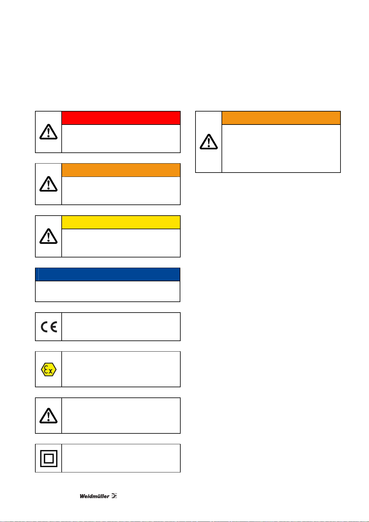
3.6 Symbol Identification
DANGER
Indicates an imminently hazardous
situation which, if not avoided, will result
in death or serious injury.
WARNING
Indicates a potentially hazardous
situation which, if not avoided, could
result in death or serious injury.
CAUTION
Indicates a potentially hazardous
situation which, if not avoided, may
result in minor or moderate injury.
NOTICE
Indicates a situation that may result in material
damage.
The CE mark proves the compliance of
the module with the essential
requirements of the directives.
Ex modules have been approved
according to the ATEX directive for use
in connection with installations in
explosive areas.
3.7 Electrical Precautions
WARNING
High voltage!
Before removing or mounting the unit,
turn off power supply.
Follow ESD installation regulations,
including EMI precautions.
3.8 General Instructions
Read and follow all instructions in this manual.
Inform yourself about hazards which can be
caused by the product.
Observe the safety and accident prevention
regulations.
Regularly check that all measures to prevent
accidents are being complied with.
Only operate the product if it is in perfect
technical condition, according to its intended
use, in awareness of safety and risks and in
adherence to the instructions in this manual.
Keep this manual and all other applicable
documents complete, legible and accessible to
personnel at all times.
Refrain from any procedures and actions that
would expose personnel or third parties to any
risk.
10
This symbol is combined with one of the
signal words DANGER, WARNING or
CAUTION to indicate a hazardous
situation.
The double insulation symbol shows that
the device is protected by double or
reinforced insulation..
1066540000/01/12.11
Page 11

Introduction
4. Introduction
4.1 Product Description
4.1.1 Product Family ACT20X
Order No. Type Description Function
8965340000 ACT20X-HDI-SDO-RNO-S NAMUR pulse isolator –
relay NO
8965350000 ACT20X-HDI-SDO-RNC-S NAMUR pulse isolator –
relay NC
8965360000 ACT20X-HDI-SDO-S NAMUR pulse isolator NAMUR in (from Ex) to
8965370000 ACT20X-2HDI-2SDO-RNO-S 2-channel
NAMUR pulse isolator –
relay NO
8965380000 ACT20X-2HDI-2SDO-RNC-S 2-channel
NAMUR pulse isolator –
relay NC
8965390000 ACT20X-2HDI-2SDO-S 2-channel
NAMUR pulse isolator
8965400000 ACT20X-SDI-HDO-L-S Solenoid/alarm driver,
L = low current max. 35 mA
8965410000 ACT20X-SDI-HDO-H-S Solenoid/alarm driver,
H = high current max. 60 mA
8965420000 ACT20X-2SDI-2HDO-S 2-channel
Solenoid/alarm driver,
L = low current max. 35 mA
NAMUR in (from Ex) to
relay out
NAMUR in (from Ex) to
relay out
digital out
2x NAMUR in (from Ex) to
2x relays out
2x NAMUR in (from Ex) to
2x relays out
2x NAMUR in (from Ex) to
2x digital out
digital in to safe digital out
(to Ex IIC)
digital in to safe digital out
(to Ex IIB)
2x digital in to 2x safe
digital out (to Ex)
8965430000 ACT20X-HAI-SAO-S HART-transparent repeater mA in (from Ex) to mA out
with HART transparency
8965440000 ACT20X-2HAI-2SAO-S 2-channel
HART-transparent repeater
8965450000 ACT20X-SAI-HAO-S HART-transparent driver mA in to mA out (to Ex)
8965460000 ACT20X-2SAI-2HAO-S 2-channel
HART-transparent driver
8965470000 ACT20X-HTI-SAO-S Temperature/mA converter temperature in (from Ex)
8965480000 ACT20X-2HTI-2SAO-S 2-channel
Temperature/mA converter
1066540000/01/12.11
2x mA in (from Ex) to 2x
mA out with HART
transparency
with HART transparency
2x mA in to 2x mA out (to
Ex) with HART
transparency
to mA out
2x temperature in (from
Ex) to 2x mA out
11
Page 12

Introduction
8965490000 ACT20X-HUI-SAO-S Universal converter universal analog in (from
Ex) to analog (V / mA) +
trip relay out
Table 4-1: Family ACT20X
12
1066540000/01/12.11
Page 13

Introduction
4.1.2 General Description
Weidmüller’s ACT20X – new signal converters for
hazardous areas: Universal family of products
covers the entire field of hazardous area
applications with six different basic functions.
With the introduction of its ACT20X modules
Weidmüller is offering a completely new family of
signal converters for hazardous area applications.
With just 11 mm per channel these compactly
designed modules require very little space in the
electrical cabinet. All ACT20X converters can be
configured via a PC utilizing the software "WIManager". This software is based on vendor-neutral
FDT/DTM technology. The innovative modules are
designed to be installed in safe or hazardous areas
of Zone 2. The ACT20X family includes digital and
analogue intrinsically safe converters that both
isolate and convert signals from as well as into
hazardous areas. The innovative signal converters
process 2-wire HART, NAMUR, RTD, thermocouple
or DC signals as well as digital signals with electrical
connection to hazardous area Zone 0. All modules
have 3-way separation and are optionally available
with dual channel functionality. With high levels of
insulation resistance, accuracy and thermal stability
ACT20X modules provide a pure, disturbance free
signal at all times. A relay-based error monitoring
facility simplifies servicing. ACT20X modules can be
utilized in temperatures from -20 °C to +60 °C
without restrictions. They have all relevant
international approvals such as ATEX, IECEx, FM –
in other words, the modules are predestined for use
in applications all over the world.
Utilizing the "WI-Manager" configuration software
based on FDT technology (Field Device Tool) makes
it possible to adapt all ACT20X products via a PC to
meet different process application requirements. For
this purpose Weidmüller provides the Device Type
Manager (DTM), which can be executed in any FDTbased frame application. As well as fast and errorfree parameterization of individual devices DTMs
make it possible to evaluate measurement and
diagnostic data. In addition, it is possible to
unambiguously identify a connected device via DTM.
ACT20X modules are equipped with a cleverly
designed connection technology that supports
simple, coded mating. The integrated release lever
ensures the connection can be disconnected without
damage when servicing is required. Devices from
the ACT20X family have been designed to operate
in an ambient temperature range of -20 °C to +60 °C
– in other words in practically all fields of industry.
The hinged and transparent front plate can easily be
opened upwards. It has been designed for simple
accommodation of device markers.
Products from the ACT20X assortment are designed
to be installed in Zone 2 / Division 2 or in nonhazardous areas; international approvals such as
ATEX, IECEx and FM (Class I, Division 1 and 2)
allow processing of signals from Zone 0 / Division 1.
Put succinctly, the modules are suitable for use in
applications across the globe.
1066540000/01/12.11
13
Page 14

Introduction
4.1.3 The Six Basic Module Types in Detail
NAMUR Pulse Isolator
The pulse isolator ACT20X-HDI-SDO is a special
signal isolator/converter for NAMUR sensor signals
from within Ex Zone 0. Transistor or relay outputs
are available on the output side. A dual-channel
version is optionally available.
Solenoid/Alarm Driver
The digital a
switch/alarm signaling facility) ACT20X-SDI-HDO is
equipped with an input in the non-hazardous area
and an output in Ex Zone 0.
HART-Transparent Repeater
The ACT
protocol transparent signal isolator for analogue
input signals from hazardous area Zone 0 sources.
Its output side provides an analogue signal for safe
area devices. A dual-channel version is optionally
available.
HART-Transparent Driver
The propo
is HART-protocol transparent. The input has been
designed for use in non-hazardous areas, the output
for Ex Zone 0. A dual-channel version is optionally
available.
Temperature/mA Converter
The ACT
isolator/converter facilitates utilization of Pt100
sensors. The input circuit is designed for intrinsically
safe signals from within Zone 0. Analogue signals
are made available on the output side for safe area
devices. A dual-channel version is optionally
available.
Universal Converter
The unive
is a user configurable temperature and signal
converter for Pt100, thermal and current (mA) inputs
from within Ex Zone 0 as well as an output for nonhazardous area devices.
ctuator driver (solenoid valve
20X-HAI-SAO signal isolator is a HART-
rtional actuator driver ACT20X-SAI-HAO
20X-HTI-SAO temperature signal
rsal isolator/converter ACT20X-HUI-SAO
Features
Full functionality interfacing with Zone 0 /
Division 1 hazardous area inputs and outputs
Approvals include use for Zone 0 (IECEx, ATEX),
Class I, Division 1 and 2 (FM).
Analogue and binary signal interfacing with
measurement and control devices.
Temperature, DC, resistance and potentiometer
inputs
Milliamp and relay/opto outputs
High quality, 3-port isolation
Dual channel options – minimizes rail space and
installation cost
HART-transparent signaling
Integral fault alarm
-20 to +60 °C ambient temperature
All modules configurable with FDT/DTM Software
"WI-Manager"
14
1066540000/01/12.11
Page 15
Installation
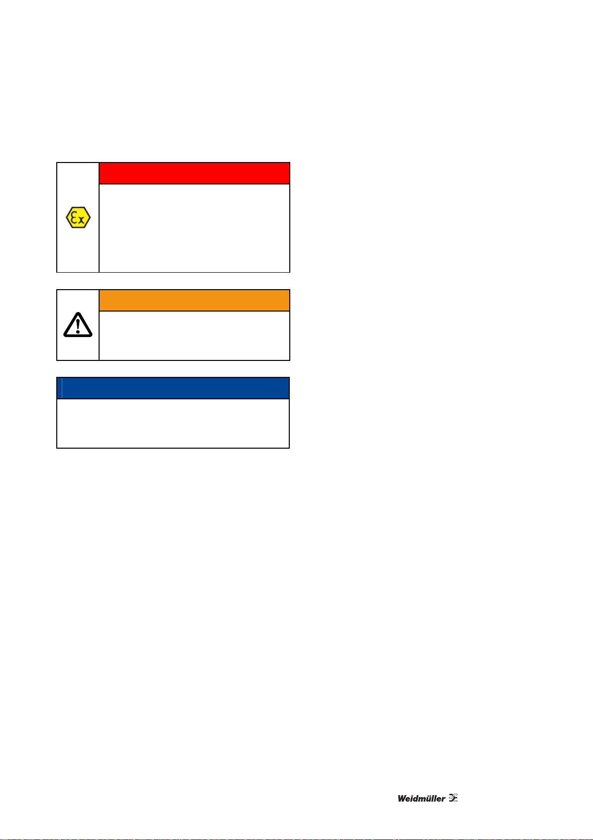
5. Installation
DANGER
Risk of explosion!
For installation in Zone 2, install the
module in an outer enclosure with IP
protection of at least IP54.
Protection must be according to type
of protection Ex-n or Ex-e.
WARNING
High voltage!
Before removing or mounting the unit,
turn off power supply.
NOTICE
Material damage through ESD!
Only carry out the following procedures under
ESD-safe conditions.
5.1 General
This product should only be installed by technically
qualified personnel with sufficient training in
instrumentation and control engineering.
VDE 0105 Part 1 / DIN EN 50110-1 defines qualified
personnel as electrically skilled workers,
electronically instructed personnel or personnel
meeting similar local standards.
5.2 Unpacking
1 Check on receipt that the product received
corresponds to the one ordered.
2 Also make sure that installation instructions have
been supplied.
3 Unpack the product carefully.
The use of stranded wires is not permitted for
mains wiring except for wires fitted with cable
ends.
Descriptions of input/output and supply
connections are shown in the block diagram and
on the side label.
The module is provided with field wiring terminals
and must be supplied from a power supply having
double/reinforced insulation.
A power switch must be easily accessible and
close to the module.
The power switch must be marked with a label
telling that it will switch off the voltage to the
module.
Year of manufacture can be taken from the first
two digits in the serial number.
Should there be any doubt as to the correct
handling of the module, contact your local
distributor.
5.1.1 Environment
This product is designed for use either indoors
(IP20) in a control panel, or in a weather-proof field
enclosure.
Avoid direct sunlight, dust, high temperatures,
mechanical vibrations and shock as well as rain
and heavy moisture.
If necessary, heating in excess of the stated limits
for ambient temperatures should be avoided by
ventilation.
Product must be installed in pollution degree 2,
overvoltage category II as defined in EN 60664-1.
Product is designed to be safe at least under an
altitude of up to 2000 m.
1066540000/01/12.11
15
Page 16
Installation
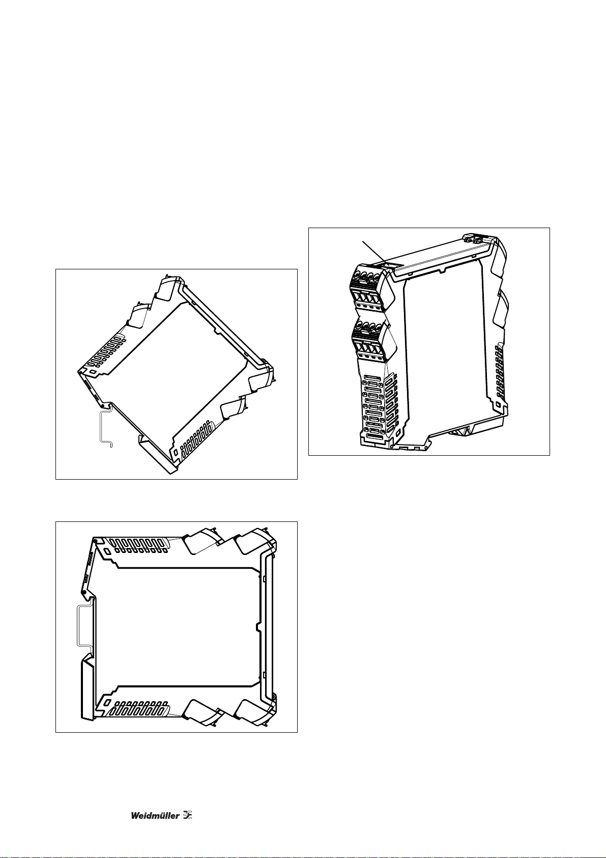
5.3 Mounting
The product is designed to be mounted onto a TS 35
DIN rail.
It clips onto the rail via a spring-loaded mounting
foot and can be removed via a spring release on the
edge of the product near the mounting rail.
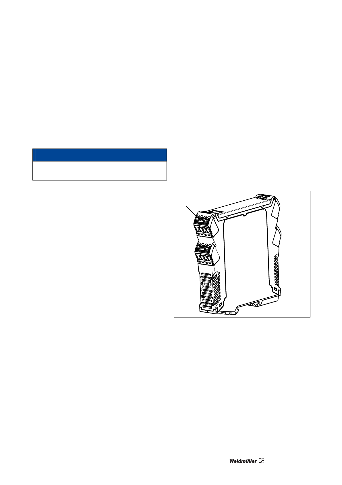
5.4 Marking
A device marker is located below the upper set of
terminals for costumer identification.
1
Illustration 5-1: Mounting, Step 1
Illustration 5-2: Mounting, Step 2
Illustration 5-3: Marking
1 Device Marker
16
1066540000/01/12.11
Page 17
Installation
5.5 Electrical Connections
See section 7, "Product Installation / Operation” for
further information.
5.5.1 EMI Protection
NOTICE
Do not install input, output and power supply
cables close to sources of electrical interference!
For example, sources of electrical interference could
include relays, contactors, motors and their controls,
including thyristor drives and the cables which
connect these devices. Avoid installing ACT20X
cables in the same ducting as such cables.
Local electrical installation practices must be
followed.
5.6 Calibration and Adjustment
During calibration and adjustment, carry out the
measuring and connection of external voltages
according to the specifications in this manual.
Only use tools and instruments that are safe to
use.
5.7 Release Lever
The terminals are released with a release lever.
1
1066540000/01/12.11
Illustration 5-4: Release Lever
1 Release lever
17
Page 18
Installation
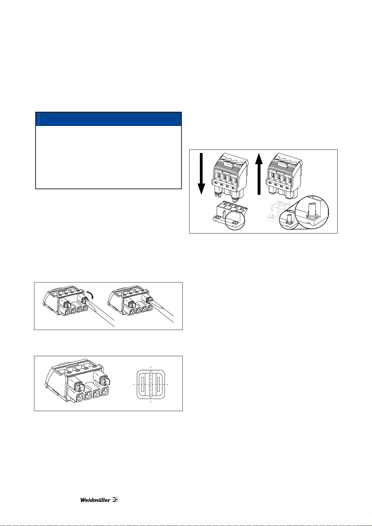
5.8 Encoding
NOTICE
Leaving the product connectors uncoded results
in lack of interchanging protection. All connectors
will be identically encoded.
Create connector coding plan prior to first
mating and encode connectors accordingly.
Perform encoding procedure for each new
module.
The product housing is equipped with an automatic
encoding.
This connector interchanging protection is initially
encoded upon shipping and can be individually
adjusted.
1 Use screw driver to turn adjusting dial of
connector clockwise.
Either dial has 4 encoding positions, resulting in
4² = 16 possible positions.
Connector is encoded.
2 Plug encoded connector onto pin header.
Encoding element is transferred from connector
to pin header.
Encoding element remains in the pin header
housing.
Illustration 5-7: Transfer Encoding Element
Illustration 5-5: Encoding Connector
3
Illustration 5-6: Encoding Positions
18
1066540000/01/12.11
0
1
2
Page 19
Installation
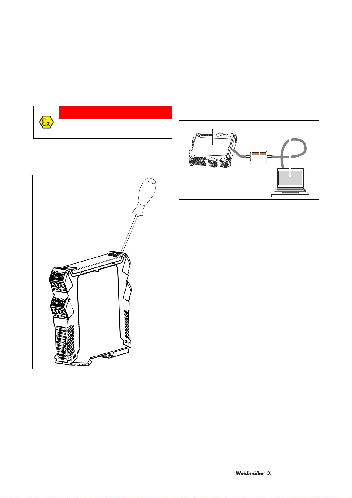
5.9 Configuration
DANGER
Configuration must be performed in a
safe area!
Configuration is performed via a connector located
behind the front flap.
1 Open the front flap, as shown in the illustration:
2 Connect the CBX200 USB jack, as shown in the
illustration:
1 23
Illustration 5-9: CBX200 USB Connection
1 Jack connection under front flap
2 CBX200 with USB connection
3 PC
3 See "WI-Manager" documentation for further
information.
Illustration 5-8: Opening Front Flap
1066540000/01/12.11
19
Page 20

Operation
6. Operation
6.1 Normal Operation
Operators are only allowed to adjust and operate
modules that are safely fixed in panels, etc., thus
avoiding the danger of personal injury and damage.
This means there is no electrical shock hazard and
the module is easily accessible.
6.2 Warm-Up
The product is designed to start-up as soon as
power is supplied. However a warm-up period of 15
minutes is required before it performs to the
specifications above.
When auxiliary power is switched on, for the first
200 ms the product will consume up to 200 mA.
6.3 Cleaning
1 Power supply switched off.
2 Clean with cloth moistened with distilled water.
20
1066540000/01/12.11
Page 21

Product Installation / Operation
7. Product Installation / Operation
7.1 ACT20X-HDI-SDO (NAMUR Pulse Isolator)
7.1.1 Description
The pulse isolator ACT20X-HDI-SDO is a special signal isolator/converter for NAMUR sensor signals from
within Ex Zone 0. The product is able for an intrinsically safe operation of NAMUR sensors or for contacts
with floating and resistance circuits.
Transistor or relay outputs are available on the output side. A dual-channel version is optionally available.
The following NAMUR pulse isolators are available:
Order No. Type Description
8965340000 ACT20X-HDI-SDO-RNO-S NAMUR pulse isolator – relay NO
8965350000 ACT20X-HDI-SDO-RNC-S NAMUR pulse isolator – relay NC
8965360000 ACT20X-HDI-SDO-S NAMUR pulse isolator
8965370000 ACT20X-2HDI-2SDO-RNO-S 2-channel NAMUR pulse isolator – relay NO
8965380000 ACT20X-2HDI-2SDO-RNC-S 2-channel NAMUR pulse isolator – relay NC
8965390000 ACT20X-2HDI-2SDO-S 2-channel NAMUR pulse isolator
1066540000/01/12.11
21
Page 22
Product Installation / Operation, ACT20X-HDI-SDO (NAMUR Pulse Isolator)
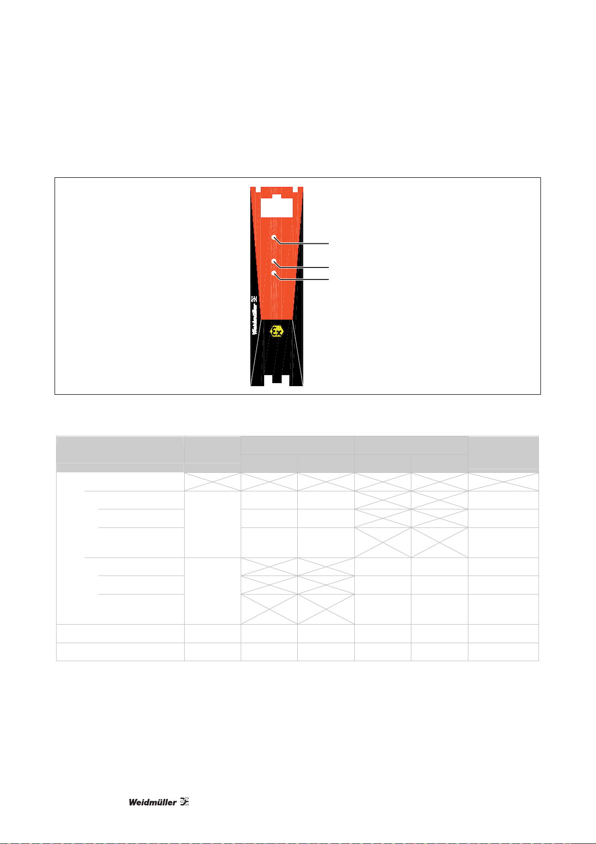
7.1.2 Status/Alarm LEDs
51
41
ACT20X
11 121314
21 222324
PWR
CH1
CH2
54
44
LED 1
LED 2
LED 3
Illustration 7-1: Status/Alarm LEDs
Condition LED 1
Channel 1 Channel 2
LED 2 Output LED 3 Output
Status
Relay (NC)
Device OK
activated yellow ON energized
de-activated OFF OFF energized
wire short/break
Channel 1
green
flashing
red
flashing
OFF de-energized
activated yellow ON energized
de-activated OFF OFF energized
wire short/break
Channel 2
green
flashing
flashing
red
OFF de-energized
No supply OFF OFF OFF OFF OFF de-energized
Device failure OFF red OFF red OFF de-energized
Flashing: 8% ON and 92% OFF __|¯|_______|¯|_______|¯|_______
Table 7-1: Status/Alarm LEDs
22
1066540000/01/12.11
Page 23
Product Installation / Operation, ACT20X-HDI-SDO (NAMUR Pulse Isolator)
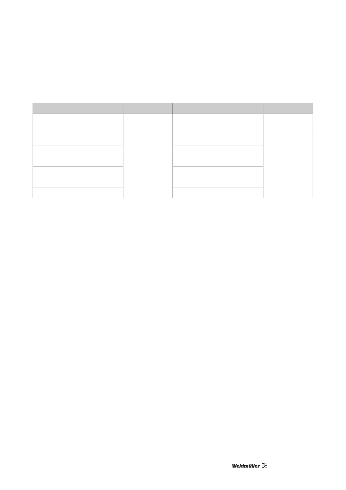
7.1.3 Electrical Connections
Terminal Function Connector Terminal Function Connector
11 SW Sense 41 COM / / OPTO +
12 NAMUR 42 NO / NC / OPTO –
13 SW Supply 43 COM / / OPTO +
14 NAMUR +
Ex input
channel 1
44 NO / NC / OPTO –
output
channel 1
output
channel 2
21 SW Sense 51 GND
power supply
22 NAMUR 52 +24 V DC
23 SW Supply 53 NC
Ex input
channel 2
status relay
24 NAMUR +
54 COM
Table 7-2: Electrical Connections
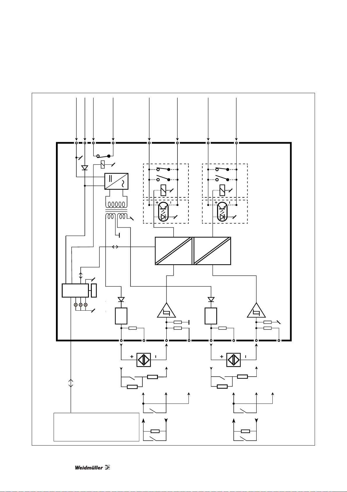
7.1.4 Function Description
(1) NAMUR sensor with cable error detection in case of cable disconnection or short circuit.
(2) Mechanical switch with cable error detection in case of cable disconnection or short circuit, when series
resistance (R
(3) Mechanical switch with cable error detection in case of cable disconnection, when parallel resistance
) is mounted on the switch.
(R
P
(4) Mechanical switch without cable error detection.
See illustration 7-2 "Functional Block Diagram" for further information.
) and parallel resistance (RP) are mounted on the switch.
S
7.1.5 Specifications
Features
Configuration and monitoring via FDT/DTM-Software "WI-Manager".
Selection of direct or inverted function for each channel.
The device can be mounted in the safe area and in Zone 2 / Division 2 and receive signals from Zone 0, 1,
2, 20, 21 and 22, as well as Class I/II/III, Division 1, Group A-G.
Extended self diagnostic: Monitoring of error events and cable breakage via the individual status relay.
LED indication for operation status and malfunction.
3-way galvanic isolation between input, output and supply.
1066540000/01/12.11
23
Page 24
Product Installation / Operation, ACT20X-HDI-SDO (NAMUR Pulse Isolator)
Gnd. -
Supply +24 VDC
Status relay N.C.
Status relay N.C.
Opto + or relay N.O.
or relay N.C.
Opto - or relay N.O.
or relay N.C.
Opto + or relay N.O.
or relay N.C.
Opto - or relay N.O.
or relay N.C.
51
525453
CPU
Device status, Green
Ch. 1 status, Yellow/Red
Ch. 2 status, Yellow/Red
FLASH
NAMUR
V
Channel 1
14
42
Channel 1
13
12
41
11
44
Channel 2
NAMUR
V
Channel 2
24
23
43
22
21
sensor
NAMUR
Switch,
cable error
p
R
CBX200 with Configuration Software
Illustration 7-2: Functional Block Diagram
24
1066540000/01/12.11
sensor
NAMUR
(2) (1)(4)(3)
s
R
p
R
Switch,
cable error
= 15 kΩ
p
R
p
R
= 750 Ω
s
R
s
R
p
R
(2) (1)(4)(3)
possible with the use of resistors Rp
and Rs, or with NAMUR sensors.
* Monitoring of cable breakage is only
* NC = no connection
Page 25
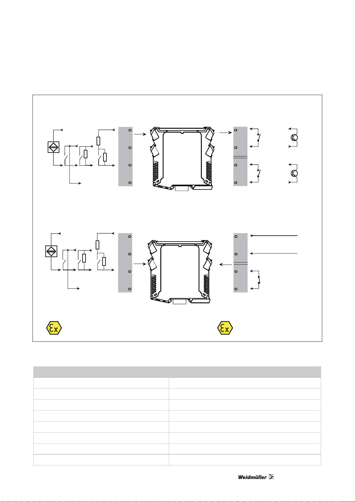
Product Installation / Operation, ACT20X-HDI-SDO (NAMUR Pulse Isolator)
Input Signals
NAMUR
+
-
Ch an n e l 1:
NAMUR
+
-
Ch an n e l 2:
Mechanical
switch
R
p
Mechanical
switch
R
p
Output Signals
14
R
s
13
R
p
12
11
44
43
42
41
Relay
Channel 2:
N.O. or
N.C.
Relay
Relay
Channel 1:
N.O. or
N.C.
Relay
Opto +
Ch. 2:
Opto -
Opto +
Ch. 1:
Opto -
Power Supply
Gnd. -
24
R
s
23
R
p
22
51
Supply +19.2...31.2 VDC
52
Module status
53
N.C.
21
Zone 0, 1, 2, 20, 21, 22 /
Cl. I/II/II I, div. 1 gr. A-G
Illustration 7-3: Applications
Input NAMUR / Mechanical Switch with Series and Parallel Resistance
NAMUR sensor, according to EN 60947-5-6
Mechanical Switch, Series resistance (RS) nom. 750 Ω
Mechanical Switch, Parallel resistance (RP) nom. 15 kΩ
Frequency range 0…5 kHz
Min. pulse length > 0.1 ms
Resistance nom. 1 kΩ
Trigger level, signal < 1.2 mA, > 2.1 mA
Trigger level, cable fault < 0.1 mA, > 6.5 mA
54
Module status
Zone 2 / FM Cl. I
div. 2, gr. A-D or safe area
1066540000/01/12.11
25
Page 26
Product Installation / Operation, ACT20X-HDI-SDO (NAMUR Pulse Isolator)
Status Relay Safe Area Zone 2 Installation
Voltage max. 125 V AC / 110 V 32 V AC / 32 V DC
Current max. 0.5 A AC / 0.3 A 0.5 A AC / 1 A DC
Power max. 62.5 VA / 32 W 16 VA / 32 W
Relay Output Safe Area Zone 2 Installation
Voltage max. 250 V AC / 30 V 32 V AC / 30 V DC
Current max. 2 A AC / 2 A DC 2 A AC / 2 A DC
Power max. 500 VA / 60 W 16 VA / 60 W
Max. switching frequency 20 Hz
Opto NPN Output
Max. switching frequency 5 kHz
Min. pulse length 60 μs
Max. load, current / voltage 80 mA / 30 V DC
Voltage drop at 80 mA < 2.5 V DC
Power Supply
Supply voltage 19.2…31.2 V DC
NAMUR supply 8 V DC / 8 mA
Max. consumption (2-channels) ≤ 3 W
Fuse 400 mA / 250 V AC
Isolation Voltages (reinforced insulation), Test/Operation
Inputs / outputs / supply 2.6 kV AC / 300 V AC
Output 1 to output 2 1.5 kV AC / 150 V AC
Status relay to supply 1.5 kV AC / 150 V AC
Environmental Specifications
Specifications range -20…+60 °C
Storage temperature -20…+85 °C
Relative humidity (non-condensation) < 95 %
Calibration temperature +20…28 °C
26
1066540000/01/12.11
Page 27

Product Installation / Operation, ACT20X-HDI-SDO (NAMUR Pulse Isolator)
General Specifications
Communications interface,
CBX200 USB / "WI-Manager" / ACT20X DTM
adapter / configuration software / FDT-DTM
device driver
Dimensions (H x W x D) 105.6 x 22.5 x 114.7 mm
Protection degree IP20
Screw terminal torque 0.5 Nm
Vibration IEC 60068-2-6, test Fc, 1g, 2…100 Hz
Vibration, continuous IEC 60068-2-64, test Fh, 1g, 3…100 Hz
Wire size, stranded wire AWG 26…14 / 0.13…2.08 mm²
Response time for cable fault < 200 ms
Default Settings
Channel 1 function direct
Channel 2 function direct
Short circuit indication yes
Breakage indication yes
1066540000/01/12.11
27
Page 28

Product Installation / Operation, ACT20X-HTI-SAO (Temperature/mA Converter)
7.2 ACT20X-HTI-SAO (Temperature/mA Converter)
7.2.1 Description
The modules of the ACT20X-HTI-SAO family transmit analog signals galvanic isolated from hazardous areas
to the safe area. The input circuits are designed intrinsically safe.
The ACT20X-HTI-SAO converts and isolates current and temperature sensor signals (mA, RTD and TC).
The two-channel version ACT20X-2HTI-2SAO can be used as a signal splitter for mA signals.
For the higher accuracy of thermo couple signals, the use of special cold junction terminals ACT20X-CJCHTI-S recommended:
1160640000 ACT20X-CJC-HTI-S PRT 11 (1-channel)
1160650000 ACT20X-CJC-HTI-S PRT 21 (2-channel)
The following converter types are available:
Order No. Type Description
8965470000 ACT20X-HTI-SAO-S Temperature/mA converter
8965480000 ACT20X-2HTI-2SAO-S 2-channel temperature/mA converter
28
1066540000/01/12.11
Page 29

Product Installation / Operation, ACT20X-HTI-SAO (Temperature/mA Converter)
7.2.2 Status/Alarm LEDs
51
41
ACT20X
11 121314
21 222324
PWR
CH1
CH2
54
44
LED 1
LED 2
LED 3
Illustration 7-4: Status/Alarm LEDs
Condition LED 1
Channel 1 Channel 2
LED 2 Output LED 3 Output
Status
Relay (NC)
Device
OK OFF ON energized
defective red fault state energized
wire short/break
Channel 1
green
flashing
red
flashing
fault state de-energized
OK OFF ON energized
defective red fault state energized
wire short/break
Channel 2
green
flashing
flashing
red
fault state de-energized
No supply OFF OFF OFF OFF OFF de-energized
Device failure OFF red OFF red OFF de-energized
Flashing: 8% ON and 92% OFF __|¯|_______|¯|_______|¯|_______
Table 7-3: Status/Alarm LEDs
1066540000/01/12.11
29
Page 30
Product Installation / Operation, ACT20X-HTI-SAO (Temperature/mA Converter)
7.2.3 Electrical Connections
Function
Terminal
mA
2W 3W 4W
11 Sense– Sense– + 41 Out
12 – R R– R– – 42 Out +
13 + R R+ R+ 43 Out
14 Sense+
21 Sense– Sense– + 51 GND
22 – R R– R– – 52 +24 V DC
23 + R R+ R+ 53 NC
24 Sense+
Table 7-4: Electrical Connections
RTD
Connector Terminal Function Connector
TC
Ex input
channel 1
44 Out +
Ex input
channel 2
54 COM
output
channel 1
output
channel 2
power
supply
status
relay
7.2.4 Specifications
Features
Configuration and monitoring are performed via FDT/DTM Software "WI-Manager".
The device can be mounted in the safe area and in Zone 2 / Division 2 and receive signals from Zone 0, 1,
2, 20, 21 and 22, as well as Class I/II/III, Division 1, Group A-G.
The passive signal inputs for RTD, TC and mA are made for one or two channels and completely
electrically isolated.
The two-channel version is suitable to use as a signal splitter.
3-way galvanic isolation between input, output and supply.
Front LEDs indicate operation status and malfunction.
The cold junction compensation for TC-signal inputs is either the internal cold junction compensation, or for
higher accuracy is an external cold junction compensation terminal available –- 1 channel 1160640000
ACT20X-CJC-HTI-S PRT 11 or 2 channel 1160650000 ACT20X-CJC-HTI-S PRT 21.
Extended self diagnostic: Monitoring of error events and cable breakage via the individual status relay.
30
1066540000/01/12.11
Page 31

Product Installation / Operation, ACT20X-HTI-SAO (Temperature/mA Converter)
Gnd.
Gnd.
2
3
tion, wries TC
RTD, connec-
4
Current
Illustration 7-5: Functional Block Diagram
1066540000/01/12.11
-
+
-
+
2
3
tion, wires TC
RTD, connec-
4
-
+
Current
-
+
31
Page 32

Product Installation / Operation, ACT20X-HTI-SAO (Temperature/mA Converter)
Channel 1
Current
+
Channel 2
Current
+
Input signals
RT D
Connection, wires
RT D
Connection, wires
TC
TC
44
14
43
13
42
12
41
11
24
23
22
21
Output signals
Analogue, 0/4...20 mA
42
41
44
43
+
mA
-
+
mA
-
2-wire supply -
4...20 mA
mA
mA
-
4...20 mA
-
2-wire supply +
2-wire supply -
2-wire supply +
Channel 1
Channel 2
Supply and module status
51
52
53
54
Supply -
Supply +19.2...31.2 VDC
Module status
N.C.
Module status
Zone 0, 1, 2, 20, 21, 22 /
Cl. I/II/III, div. 1 gr. A-G
Zone 2 / FM Cl. 1,
div. 2, gr. A-D or safe area
Illustration 7-6: Applications
RTD Input
Pt100, according to -200…+850 °C, IEC 60751
Ni100, according to -60…+250 °C, DIN 43760
Sensor types
(* = without short circuit detection)
Pt10*, Pt20*, Pt50*, Pt100, Pt250, Pt300, Pt400,
Pt500, Pt1000, Ni50, Ni100, Ni120, Ni1000
Cable resistance per wire (max.) 50 Ω
Sensor current nom. 0.2 mA
Effect of sensor cable resistance (3/4-wire) < 0.002 Ω
Sensor error detection (programmable) ON/OFF
32
1066540000/01/12.11
Page 33

Product Installation / Operation, ACT20X-HTI-SAO (Temperature/mA Converter)
Sensor error current:
when detecting
else
< 2 μA
0 μA
TC Input, Sensor Types Temperature Range Standard
B 0…+1820 °C IEC 60584-1
E -100…+1000 °C IEC 60584-1
J -100…+1200 °C IEC 60584-1
K -180…+1372 °C IEC 60584-1
L -200…+900 °C DIN 43710
N -180…+1300 °C IEC 60584-1
R -50…+1760 °C IEC 60584-1
S -50…+1760 °C IEC 60584-1
T -200…+400 °C IEC 60584-1
U -200…+600 °C DIN 43710
W3 0…+2300 °C ASTM E988-90
W5 0…+2300 °C ASTM E988-90
LR -200…+800 °C GOST 3044-84
Accuracy, General Values Absolute Accuracy Temperature Coefficient
All ≤ 0.1 % of span ≤ 0.01 % of span / °C
Accuracy, Basic Values Absolute Accuracy Temperature Coefficient
mA ≤ 16 μA ≤ 1.6 μA / °C
Pt100, Pt200, Pt1000 ≤ 0.2 °C ≤ 0.02 C / °C
Pt500, Ni100, Ni120, Ni1000 ≤ 0.3 °C ≤ 0.03 C / °C
Pt50, Pt400, Ni50 ≤ 0.4 °C ≤ 0.04 C / °C
Pt250, Pt300 ≤ 0.6 °C ≤ 0.06 C / °C
Pt20 ≤ 0.8 °C ≤ 0.08 C / °C
Pt10 ≤ 1.4 °C ≤ 0.14 C / °C
TC type: E, J, K, L, N, T, U ≤ 1 °C ≤ 0.1 C / °C
TC type: R, S, W3, W5, LR ≤ 2 °C ≤ 0.2 C / °C
TC type: B (160…400 °C) ≤ 4.5 °C ≤ 0.45 C / °C
TC type: B (400…1820 °C) ≤ 2 °C ≤ 0.2 C / °C
1066540000/01/12.11
33
Page 34

Product Installation / Operation, ACT20X-HTI-SAO (Temperature/mA Converter)
TC Input, Cold Junction Compensation (CJC)
CJC: external with ACT20X-CJC-HTI
(1160640000 or 1160650000)
CJC via internal sensor
+20…+28 °C ≤ 1 °C
-20…+20 °C and +28…+60 °C≤ 1.6 °C
(2.0 °C + 0.2 °C * t)
t = internal temperature – ambient temperature
Sensor error detection (programmable, only wire
ON/OFF
breakage)
Sensor error current:
when detecting
else
nom. 2 μA
0 μA
Current Input
Measurement range 0…20 mA
Programmable measurement ranges 0…20 / 4…20 mA
Input resistance nom. 20 Ω + PTC 50 Ω
Sensor error detection (programmable) ON/OFF
Current Output
Programmable signal ranges 0…20 mA / 4…20 mA / 20…0 mA / 20…4 mA
Load max. 4 mA / 600 Ω / 12 V DC
Load stability ≤ 0.01 % of span / 100 Ω
Sensor error detection 0 / 3.5 mA / 23 mA / none
Output limitation:
on 4…20 and 20…4 mA signals
on 0…20 and 20…0 mA signals
3.8…20.5 mA
0…20.5 mA
Current limit ≤ 28 mA
2-wire 4…20 mA Loop Powered Output
Signal range 4…20 mA
Load resistance ≤ (V
– 3.5 V) / 0.023 A [Ω]
supply
Load stability ≤ 0.01 % of span / 100 Ω
Max. external 2-wire supply 3.5…26 V DC
Effect of external 2-wire supply voltage variation < 0.005 % of span / V
34
1066540000/01/12.11
Page 35

Product Installation / Operation, ACT20X-HTI-SAO (Temperature/mA Converter)
Status Relay Safe Area Zone 2 Installation
Voltage max. 125 V AC / 110 V 32 V AC / 32 V DC
Current max. 0.5 A AC / 0.3 A 0.5 A AC / 1 A DC
Power max. 62.5 VA / 32 W 16 VA / 32 W
Power Supply
Supply voltage 19.2…31.2 V DC
Max. consumption (2-channels) ≤ 3.5 W
Fuse 1.25 A / 250 V AC
Isolation Voltages (reinforced insulation), Test/Operation
Inputs / outputs / supply 2.6 kV AC / 300 V AC
Output 1 to output 2 1.5 kV AC / 150 V AC
Status relay to supply 1.5 kV AC / 150 V AC
Environmental Specifications
Ambient temperature -20…+60 °C
Storage temperature -20…+85 °C
Relative humidity (non-condensation) < 95 %
Calibration temperature +20…28 °C
General Specifications
Communications interface,
CBX200 USB / "WI-Manager" / ACT20X DTM
adapter / configuration software / FDT-DTM
device driver
Dimensions (H x W x D) 105.6 x 22.5 x 114.7 mm
Protection degree IP20
Screw terminal torque 0.5 Nm
Vibration IEC 60068-2-6, test Fc, 1g, 2…100 Hz
Vibration, continuous IEC 60068-2-64, test Fh, 1g, 3…100 Hz
Wire size, stranded wire AWG 26…14 / 0.13…2.08 mm²
EMC immunity influence ≤ 0.5 % of span
Extended EMC immunity:
≤ 1 % of span
NAMUR NE 21, A criterion, burst
Signal/Noise ratio min. 60 dB (0…100 kHz)
1066540000/01/12.11
35
Page 36

Product Installation / Operation, ACT20X-HTI-SAO (Temperature/mA Converter)
Average response time incl. delay:
Temperature input
mA input
≤ 1 s
≤ 0.4 s
Default Settings
Input type Temperature
Connection type 3-wire
Temperature unit °C
Temperature sensor type Pt100
Temperature range 0…150°C
Output current range 0…20 mA
Output current on error 0…23 mA
Analog output response time (1/10 s) 1 s
36
1066540000/01/12.11
Page 37

Product Installation / Operation, ACT20X-SDI-HDO (Solenoid/Alarm Driver)
7.3 ACT20X-SDI-HDO (Solenoid/Alarm Driver)
7.3.1 Description
The ACT20X-SDI-HDO is a solenoid/alarm driver for the control of solenoids, acoustic alarms and LEDs
mounted in the hazardous area (Ex Zone 0).
Optionally one or two channel versions available.
The following solenoid/alarm drivers are available:
Order No. Type Description
8965400000 ACT20X-SDI-HDO-L-S Solenoid/alarm driver,
L = low current max. 35 mA
8965410000 ACT20X-SDI-HDO-H-S Solenoid/alarm driver,
H = high current max. 60 mA
8965420000 ACT20X-2SDI-2HDO-S 2-channel solenoid/alarm driver,
L = low current max. 35 mA
1066540000/01/12.11
37
Page 38

Product Installation / Operation, ACT20X-SDI-HDO (Solenoid/Alarm Driver)
7.3.2 Status/Alarm LEDs
51
41
ACT20X
11 121314
21 222324
PWR
CH1
CH2
54
44
LED 1
LED 2
LED 3
Illustration 7-7: Status/Alarm LEDs
Condition LED 1
Channel 1 Channel 2
LED 2 Output LED 3 Output
Status
Relay (NC)
Device OK
activated yellow ON energized
green
flashing
de-activated
Channel 1
OFF OFF energized
activated yellow ON energized
green
flashing
de-activated
Channel 2
OFF OFF energized
No supply OFF OFF OFF OFF OFF de-energized
Device failure OFF red OFF red OFF de-energized
Flashing: 8% ON and 92% OFF __|¯|_______|¯|_______|¯|_______
Table 7-5: Status/Alarm LEDs
38
1066540000/01/12.11
Page 39

Product Installation / Operation, ACT20X-SDI-HDO (Solenoid/Alarm Driver)
7.3.3 Electrical Connections
Terminal Function Connector Terminal Function Connector
11 GND 41 In
12 Ex 1 42 In +
13 Ex 2 43 In
14 Ex 3
21 GND 51 GND
22 Ex 1 52 +24 V DC
23
24 Ex 3
Table 7-6: Electrical Connections
Ex 2 53 COM
Ex output
channel 1
44 In +
Ex output
channel 2
54 NC
input
channel 1
input
channel 2
power supply
status relay
7.3.4 Specifications
Features
Solenoid/alarm driver for the control of solenoids, acoustic alarms and LEDs installed in the hazardous
area.
Two hardware versions make it possible to choose either low (35 mA) or high (60 mA) current output with
1-channel or 2-channel versions.
Configuration and monitoring via FDT/DTM-Software "WI-Manager".
Selection of direct or inverted function for each channel and the possibility of reducing the output current to
the hazardous area to suit the application.
The device can be mounted in the safe area and in Zone 2 / Division 2 and receive signals from Zone 0, 1,
2, 20, 21 and 22, as well as Class I/II/III, Division 1, Group A-G.
Extended self diagnostic: Monitoring of error events via the individual status relay.
LED indication: green and 2 yellow/red front LEDs to indicate operation status and malfunction.
3-way galvanic isolation between input, output and supply, 2.6 kV AC.
1066540000/01/12.11
39
Page 40

Product Installation / Operation, ACT20X-SDI-HDO (Solenoid/Alarm Driver)
Gnd. -
51
Status relay N.C.
Supply +24 VDC
525453
Status relay N.C.
V
+
Input +
42
NPN
Switch
CPU
PNP
V
+
41
Input Gnd.
EEPROM
V
+
Input +
44
NPN
Switch
PNP
V
+
43
Input Gnd.
CPU
Device status, Green
Ch. 1 status, Yellow/Red
Ch. 2 status, Yellow/Red
FLASH
Driver
R Ex3
14
Output +
R Ex2
13
CBX200 with Configuration Software
Illustration 7-8: Functional Block Diagram
40
1066540000/01/12.11
R Ex1
12
11
Output, Gnd.
Channel 1
R Ex3
24
Input +
R Ex2
23
R Ex1
22
Channel 2
21
Output, Gnd.
Page 41

Product Installation / Operation, ACT20X-SDI-HDO (Solenoid/Alarm Driver)
Ex Output Signals
Alarm Solenoid
14
13
Ch an n e l 1:
12
11
Input Signals
44
43
42
41
V
+
V
+
V
+
V
+
Power Supply
Alarm Solenoid
24
23
Ch an n e l 2:
22
21
51
52
53
54
GND -
+19.2...31.2 V DC
Module status
N.C .
Module status
Zone 0, 1, 2, 20, 21, 22 /
Cl. I/II/III, div. 1 gr. A-G
Illustration 7-9: Applications
NPN Input (NPN and mechanical switch)
Trigger level (low) ≤ 2 V DC
Trigger level (high) ≥ 4 V DC
Max. external voltage 28 V DC
Input impedance 3.5 kΩ
PNP Input
Trigger level (low) ≤ 8 V DC
Trigger level (high) ≥ 10 V DC
1066540000/01/12.11
Zone 2 / Cl. 1, div. 2,
gr. A-D or safe area
41
Page 42

Product Installation / Operation, ACT20X-SDI-HDO (Solenoid/Alarm Driver)
Max. external voltage 28 V DC
Input impedance 3.5 kΩ
Output
Output ripple < 40 mV RMS
ACT20X-SDI-HDO-L-S, ACT20X-2SDI-HDO-S,
low current (< 35 mA),
V
no load V
out
with load I
out
max.
out
Ex barrier data channel 1
11–12 min. 24 V min. 12.5 V 35 mA
11–13 min. 24 V min. 13.5 V 35 mA
11–14 min. 24 V min. 14.5 V 35 mA
ACT20X-2SDI-HDO-S,
low current (< 35 mA),
V
no load V
out
with load I
out
max.
out
Ex barrier data channel 2
21–22 min. 24 V min. 12.5 V 35 mA
21–23 min. 24 V min. 13.5 V 35 mA
21–24 min. 24 V min. 14.5 V 35 mA
ACT20X-SDI-HDO-H-S,
high current (< 60 mA),
V
no load V
out
with load I
out
max.
out
Ex barrier data channel 1
min. 9 V 60 mA
11–12 min. 24 V
min. 11.5 V 50 mA
min. 10 V 60 mA
11–13 min. 24 V
min. 12.5 V 50 mA
min. 11 V 60 mA
11–14 min. 24 V
min. 13.5 V 50 mA
Status Relay Safe area Zone 2 Installation
Voltage max. 125 V AC / 110 V DC 32 V AC / 32 V DC
Current max. 0.5 A AC / 0.3 A DC 0.5 AC / 0.1 A DC
Power max. 62.5 VA / 32 W 16 VA / 32 W
42
1066540000/01/12.11
Page 43

Product Installation / Operation, ACT20X-SDI-HDO (Solenoid/Alarm Driver)
Power Supply
Supply voltage 19.2…31.2 V DC
Max. consumption (2-channels) ≤ 3.5 W
Fuse 1.25 A / 250 V AC
EMC immunity influence < ±0.5 % of span
Extended EMC immunity:
< ±1 % of span
NAMUR NE 21, A criterion, burst
Isolation Voltages (reinforced insulation), Test/Operation
Inputs / outputs / supply 2.6 kV AC / 300 V AC
Output 1 to output 2 1.5 kV AC / 150 V AC
Status relay to supply 1.5 kV AC / 150 V AC
Environmental Specifications
Ambient temperature -20…+60 °C
Storage temperature -20…+85 °C
Relative humidity (non-condensation) < 95 %
Calibration temperature +20…28 °C
General Specifications
Communications interface,
CBX200 USB / "WI-Manager" / ACT20X DTM
adapter / configuration software / FDT-DTM
device driver
Dimensions (H x W x D) 105.6 x 22.5 x 114.7 mm
Protection degree IP20
Screw terminal torque 0.5 Nm
Wire size, stranded wire AWG 26…14 / 0.13…2.08 mm²
Default Settings
Channel 1 function Direct
Channel 2 function Direct
1066540000/01/12.11
43
Page 44

Product Installation / Operation, ACT20X-HUI-SAO (Universal Converter)
7.4 ACT20X-HUI-SAO (Universal Converter)
7.4.1 Description
The device ACT20X-HUI-SAO-S transmits analog signals from hazardous areas safely galvanically
separated into non or less hazardous areas. The input circuits are designed intrinsically safe.
The ACT20X-HUI-SAO-S converts and isolates current, voltage, potentiometer and temperature sensor
signals (mA, V, potentiometer, RTD and TC).
For the higher accuracy of thermocouple signals, the use of special cold junction terminal ACT20X-CJC-HTIS is recommended:
1160640000 ACT20X-CJC-HTI-S PRT 11 (1-Kanal)
The following converter type is available:
Order No. Type Description
8965490000 ACT20X-HUI-SAO-S Universal converter
44
1066540000/01/12.11
Page 45

Product Installation / Operation, ACT20X-HUI-SAO (Universal Converter)
7.4.2 Status/Alarm LEDs
51
41
ACT20X
11 121314
21 222324
PWR
CH1
CH2
54
44
LED 1
LED 2
LED 3
Illustration 7-10: Status/Alarm LEDs
Condition LED 1 LED 2
Output
Analog
Output
Relay
LED 3
(Error)
Status
Relay (NC)
Device/Signal
OK 1) active 1) OFF energized
OK and wire
short/break
de-activated
and wire
short/break
green
flashing
1) fault state 1)
1) fault state 1)
red
flashing
red
flashing
energized
energized
Output relay
activated yellow energized
de-activated
green
flashing
OFF de-energized
No supply OFF OFF OFF de-energized OFF de-energized
Device failure OFF red OFF de-energized red de-energized
Flashing: 8% ON and 92% OFF __|¯|_______|¯|_______|¯|_______
1) depends on configuration
Table 7-7: Status/Alarm LEDs
1066540000/01/12.11
45
Page 46

Product Installation / Operation, ACT20X-HUI-SAO (Universal Converter)
7.4.3 Electrical Connections
Function
Terminal
11 + 3W / 4W 41 Out
12 – / CJC 2W / 3W / 4W M3 42 Out +
13 CJC 2W /3W / 4W M1 43 COM
14 4W M2 44 NO
21 – – 51 +24 V DC
22 + – 52 GND
23
24
Table 7-8: Electrical Connections
TC RTD POT V mA
+ 53 NC
+ 54 COM
mA
Loop
Terminal Function Connector
output
output
relay
power
supply
status
relay
7.4.4 Specifications
Features
Configuration and monitoring via FDT/DTM-Software "WI-Manager".
The device can be mounted in the safe area and in Zone 2 / Division 2 and receive signals from Zone 0, 1,
2, 20, 21 and 22, as well as Class I/II/III, Division 1, Group A-G.
The active or passive signal inputs for RTD, TC, potentiometer, V and mA are completely electrically
isolated.
The device detects automatically whether an active or passive current signal is connected.
The cold junction compensation for TC-signal inputs is either the internal cold junction compensation, or for
higher accuracy is an external cold junction compensation terminal available –- 1 channel 1160640000
ACT20X-CJC-HTI-S PRT 11.
Extended self diagnostic: Monitoring of error events (e.g. cable breakage) via status relay.
Front LEDs indicates operation status and malfunction.
3-way galvanic isolation between input, output and power supply.
46
1066540000/01/12.11
Page 47

Product Installation / Operation, ACT20X-HUI-SAO (Universal Converter)
4...20 mA
Supply -
Supply +24 VDC
51
Gnd.
CPU
Channel 1 status, Red
Device status, Red/Green
Status relay N.C.
525453
FLASH
Channel 2 status, Red
RTD and lin. R,
Potentiometer
Status relay N.C.
0.2 mA
14
2
3
wires TC
connection,
4
Supply
2-wire supply -
I+
42
13
D / A
A / D
MUX
mA mA
CPU
PTC
2-wire supply +
41
12
-
Gnd.
CPU /
CJC on PCB
+
Safety
11
V
loop
24
Relay N.O.
44
EEPROM
23
+
Relay N.O.
43
-
Tx
10
PTC
22
+
21
Voltage
-
Current
2-wire transmitter
CBX200 with Configuration Software
Illustration 7-11: Functional Block Diagram
1066540000/01/12.11
47
Page 48

Product Installation / Operation, ACT20X-HUI-SAO (Universal Converter)
Input signals Output signals
Potenti-
ometer
Ch an n el 1:
* Order separately:
CJC connector
Ch an n el 2:
RTD and lin. R TC
Connection, wir es
Current Voltage
+
Tx
-
+
Analogue, 0/4...20 mA and relay
14
14
13
*
13
12
12
11
11
42
41
44
43
+
mA
-
Relay
NO
Relay
mA
+
Power connection
24
23
+
22
21
51
52
53
54
Gnd.
Supply +19.2...31.2 VDC
Device status
NC
Device status
Supply via
power rail
Zone 0, 1, 2, 20, 21, 22 /
Cl. I/II/III, div. 1 gr. A-G
Illustration 7-12: Applications
RTD, Resistance and Potentiometer Input
Pt100, according to -200…+850 °C, IEC 60751
Ni100, according to -60…+250 °C, DIN 43760
Resistance
(without short circuit detection in the range
R = 0…18Ω, appr.)
Potentiometer 10 Ω…10 kΩ
Sensor types
(* = without short circuit detection)
Cable resistance per wire (max.) 50 Ω
Sensor current nom. 0.2 mA
Effect of sensor cable resistance (3/4-wire) < 0.002 Ω
0…10 kΩ
Pt10*, Pt20*, Pt50*, Pt100, Pt250, Pt300, Pt400,
Pt500, Pt1000, Ni50, Ni100, Ni120, Ni1000
Zone 2 / FM Cl. 1,
div. 2, gr. A-D or safe area
48
1066540000/01/12.11
Page 49

Product Installation / Operation, ACT20X-HUI-SAO (Universal Converter)
Sensor error detection (programmable) ON/OFF
Short circuit detection, RTD Yes
TC Input, Sensor Types Temperature Range Standard
B 0…+1820 °C IEC 60584-1
E -100…+1000 °C IEC 60584-1
J -100…+1200 °C IEC 60584-1
K -180…+1372 °C IEC 60584-1
L -200…+900 °C DIN 43710
N -180…+1300 °C IEC 60584-1
R -50…+1760 °C IEC 60584-1
S -50…+1760 °C IEC 60584-1
T -200…+400 °C IEC 60584-1
U -200…+600 °C DIN 43710
W3 0…+2300 °C ASTM E988-90
W5 0…+2300 °C ASTM E988-90
LR -200…+800 °C GOST 3044-84
Accuracy, General Values Absolute Accuracy Temperature Coefficient
All ≤ 0.1 % of span ≤ 0.01 % of span / °C
Accuracy, Basic Values Absolute Accuracy Temperature Coefficient
mA ≤ 16 μA ≤ 1.6 μA / °C
Volt ≤ 20 μV ≤ 2 μV / °C
Pt100, Pt200, Pt1000 ≤ 0.2 °C ≤ 0.02 C / °C
Pt500, Ni100, Ni120, Ni1000 ≤ 0.3 °C ≤ 0.03 C / °C
Pt50, Pt400, Ni50 ≤ 0.4 °C ≤ 0.04 C / °C
Pt250, Pt300 ≤ 0.6 °C ≤ 0.06 C / °C
Pt20 ≤ 0.8 °C ≤ 0.08 C / °C
Pt10 ≤ 1.4 °C ≤ 0.14 C / °C
TC type: E, J, K, L, N, T, U ≤ 1 °C ≤ 0.1 C / °C
TC type: R, S, W3, W5, LR ≤ 2 °C ≤ 0.2 C / °C
TC type: B (160…400 °C) ≤ 4.5 °C ≤ 0.45 C / °C
TC type: B (400…1820 °C) ≤ 2 °C ≤ 0.2 C / °C
1066540000/01/12.11
49
Page 50

Product Installation / Operation, ACT20X-HUI-SAO (Universal Converter)
TC Input, Cold Junction Compensation (CJC)
CJC: external with ACT20X-CJC-HTI
(1160640000)
CJC via internal sensor
+20…+28 °C ≤ 1 °C
-20…+20 °C and +28…+60 °C ≤ 1.6 °C
(2.0 °C + 0.4 °C * t)
t = internal temperature – ambient temperature
Sensor error detection (programmable, only wire
ON/OFF
breakage)
Sensor error current:
when detecting
else
nom. 2 μA
0 μA
Current Input
Measurement range 0…20 mA
Programmable measurement ranges 0…20 and 4…20 mA
Input resistance nom. 20 Ω + PTC 50 Ω
Sensor error detection:
loop break (only when input is selected as
Yes
4…20 mA)
Voltage Input
Measurement range 0…12 V DC
Programmable measurement ranges 0…1 V / 0.2…1 V / 0…5 V / 1…5 V / 0…10 V /
2…10 V
Input resistance nom. > 10 MΩ
Current Output
Signal range (span) 0…23 mA
Programmable signal ranges 0…20 mA / 4…20 mA / 20…0 mA / 20…4 mA
Load max. 4 mA / 600 Ω / 12 V DC
Load stability ≤ 0.01 % of span / 100 Ω
Sensor error detection 0 / 3.5 mA / 23 mA / none
NAMUR NE 43, Upscale / Downscale 23 mA / 3.5 mA
Output limitation:
on 4…20 and 20…4 mA signals
on 0…20 and 20…0 mA signals
3.8…20.5 mA
0…20.5 mA
Current limit ≤ 28 mA
50
1066540000/01/12.11
Page 51

Product Installation / Operation, ACT20X-HUI-SAO (Universal Converter)
2-wire 4…20 mA Output
Signal range 4…20 mA
Load resistance ≤ (V
– 3.5 V) / 0.023 A [Ω]
supply
Load stability ≤ 0.01 % of span / 100 Ω
Max. external 2-wire supply 3.5…26 V DC
Effect of external 2-wire supply voltage variation < 0.005 % of span / V
Relay Output Safe Area Zone 2 Installation
Voltage max. 250 V AC / 30 V DC 32 V AC / 30 V DC
Current max. 2 A AC / 2 A DC 2 A AC / 2 A DC
Power max. 500 VA / 60 W 64 VA / 60 W
Relay functions Setpoint, Window, Sensor error, Power and Off
Hysteresis in % / display counts 0.1…25 % / 1…2999
On and Off delay 0…3600 s
Sensor error detection Break / Make / Hold
Status Relay Safe Area Zone 2 Installation
Voltage max. 125 V AC / 110 V DC 32 V AC / 32 V DC
Current max. 0.5 A AC / 0.3 A DC 0,5 A AC / 1 A DC
Power max. 62.5 VA / 32 W 16 VA / 32 W
Power Supply
Supply voltage 19.2…31.2 V DC
Max. consumption ≤ 3.5 W
Fuse 1.25 A / 250 V AC
Isolation Voltages (reinforced insulation), Test/Operation
Inputs / outputs / supply 2.6 kV AC / 300 V AC
Status relay to supply 1.5 kV AC / 150 V AC
Environmental Specifications
Ambient temperature -20…+60 °C
Storage temperature -20…+85 °C
Relative humidity (non-condensation) < 95 %
1066540000/01/12.11
51
Page 52

Product Installation / Operation, ACT20X-HUI-SAO (Universal Converter)
Calibration temperature +20…28 °C
General Specifications
Communications interface,
CBX200 USB / "WI-Manager" / ACT20X DTM
adapter / configuration software / FDT-DTM
device driver
Dimensions (H x W x D) 105.6 x 22.5 x 114.7 mm
Protection degree IP20
Screw terminal torque 0.5 Nm
Vibration IEC 60068-2-6, test Fc, 1g, 2…100 Hz
Vibration, continuous IEC 60068-2-64, test Fh, 1g, 3…100 Hz
Wire size, stranded wire AWG 26…14 / 0.13…2.08 mm²
EMC immunity influence ≤ 0.5 % of span
Extended EMC immunity:
≤ 1 % of span
NAMUR NE 21, A criterion, burst
Signal/Noise ratio min. 60 dB (0…100 kHz)
Response time (0…90 %, 100…10 %):
Temperature input, programmable
mA / V input, programmable
1…60 s
0.4…60 s
Default Settings
Input type Temperature
Connection type 3-wire
Temperature unit °C
Temperature sensor type Pt100
Temperature range 0…150 °C
Output current range 0…20 mA
Output current on error 23 mA
Analog output response time (1/10 s) 1 s
Relay Software Parameters / Default Settings
Function SETPOINT
Contact function Normally Open (NO)
Setpoint 50 °C (input type temperature) / 50 %
Activation direction Increasing
Hysteresis 1 °C (input type temperature) / 1 %
52
1066540000/01/12.11
Page 53

Product Installation / Operation, ACT20X-HUI-SAO (Universal Converter)
Action on error Relay OPEN
Activation delay 0 s
Deactivation delay 0 s
ON delay OFF- delay
Hysteresis
Hysteresis
Setpoint high
Setpoint low
Closed
Relay contact (N.O.)
Open
Window
Relay On Relay On
Illustration 7-13: Graphic depiction of window
Input
signal
Setpoint
(increasing)
Hysteresis
ON delay
ON delay OFF delay
Time
OFF delay
Closed
Relay contact
(N.O.)
Open
Illustration 7-14: Graphic depiction of setpoint
1066540000/01/12.11
Time
Relay On
53
Page 54

Product Installation / Operation, ACT20X-HAI-SAO (HART-transparent Repeater)
7.5 ACT20X-HAI-SAO (HART-transparent Repeater)
7.5.1 Description
The ACT20X-HAI-SAO-S current supply isolator is a HART-protocol, transparent isolator for analogue input
signals from Ex Zone 0. The input may also operate as an active current loop (the loop current provided by
the device). It provides an 4...20 mA current signal for the safe zone on the output side.
It is available in a single-channel or two-channel version.
The following HART-transparent repeaters are available:
Order No. Type Description
8965430000 ACT20X-HAI-SAO-S HART-transparent repeater
8965440000 ACT20X-2HAI-2SAO-S 2-channel HART-transparent repeater
54
1066540000/01/12.11
Page 55

Product Installation / Operation, ACT20X-HAI-SAO (HART-transparent Repeater)
7.5.2 Status/Alarm LEDs
51
41
ACT20X
11 121314
21 222324
PWR
CH1
CH2
54
44
LED 1
LED 2
LED 3
Illustration 7-15: Status/Alarm LEDs
Condition LED 1
Channel 1 Channel 2
LED 2 Output LED 3 Output
Status
Relay (NC)
Device OK
activated OFF active energized
defective red inactive de-energized
signal limit
exceeded
green
flashing
red
flashing
inactive de-energized
Channel 1
fixed loop break
limit exceeded
red
blinking
inactive de-energized
activated OFF active energized
defective red inactive de-energized
signal limit
exceeded
green
flashing
flashing
red
inactive de-energized
Channel 2
fixed loop break
limit exceeded
red
blinking
inactive de-energized
No supply OFF OFF OFF OFF OFF de-energized
Device failure OFF red OFF red OFF de-energized
Blinking: 50% ON and 50% OFF __|¯¯¯¯|____|¯¯¯¯|____|¯¯¯¯|____
Flashing: 8% ON and 92% OFF __|¯|_______|¯|_______|¯|_______
Table 7-9: Status/Alarm LEDs
1066540000/01/12.11
55
Page 56

Product Installation / Operation, ACT20X-HAI-SAO (HART-transparent Repeater)
7.5.3 Electrical Connections
Terminal Function Connector Terminal Function Connector
11 I Passive 41 Out
12 I Passive + 42 Out +
13 I Active Return 43 Out
14 I Active Supply
21 I Passive 51 GND
22 I Passive + 52 +24 V DC
23 I Active Return 53 NC
24 I Active Supply
Table 7-10: Electrical Connections
Ex input
channel 1
44 Out +
Ex input
channel 2
54 COM
output
channel 1
output
channel 2
power supply
status relay
7.5.4 Specifications
Features
HART-compatible for 0.5...2.5 kHz
Configuration and monitoring via FDT/DTM-Software "WI-Manager".
The device can be mounted in the safe area and in Zone 2 / Division 2 and receive signals from Zone 0, 1,
2, 20, 21 and 22, as well as Class I/II/III, Division 1, Group A-G.
The active or passive mA current signal inputs are completely electrically isolated.
The device detects automatically whether an active or passive current signal is connected.
The two-channel device can be used as a signal splitter.
Extended self diagnostic: Monitoring of error events (e.g. cable breakage) via status relay.
Front LEDs indicates operation status and malfunction.
3-way galvanic isolation between input, output and power supply.
56
1066540000/01/12.11
Page 57

Product Installation / Operation, ACT20X-HAI-SAO (HART-transparent Repeater)
Supply -
Supply +24 VDC
51
525453
FLASH
Status relay N.C.
Status relay COM
4...20 mA
2-wire supply
I+
42
4...20 mA
2-wire supply
+
+
-
mA
Gnd.
41
I+
44
mA
-
Gnd.
43
Channel 2
CPU
Supply, Green
Ch. 1 status, Red
Ch. 2 status, Red
14
+
Tx
2-wire transmitter
13
-
CBX200 with Configuration Software
Illustration 7-16: Functional Block Diagram
12
+
Channel 1
11
-
24
2-wire transmitter
23
Tx
-
+
22
21
+
-
1066540000/01/12.11
57
Page 58

Product Installation / Operation, ACT20X-HAI-SAO (HART-transparent Repeater)
Input signals Output signals
Analogue, 4...20 mA
Tx
+
Channel 1:Channel 2:
Current
-
Tx
+
Current
-
+
-
14
13
12
11
42
mA
41
44
mA
43
+
-
+
-
2-wire supply –
4...20 mA
mA
-
2-wire supply +
2-wire supply –
4...20 mA
mA
-
2-wire supply +
Power Supply and Module Status
+
-
24
23
22
21
51
52
53
54
Gnd.
Supply +19.2...31.2 V DC
Module status
N.C.
Module status
Zone 0, 1, 2, 20, 21, 22 /
Cl. I/II/III, div. 1 gr. A-G
Illustration 7-17: Applications
Current Input
Measurement range 3.5…23 mA
Alarm setpoint, low/high limit (programmable) 0…28 mA
Sensor error detection < 1 mA
Current Output
Signal range (programmable) 3.5…23 mA
Load max. 20 mA / 600 Ω / 12 V DC
Load stability ≤ 0.01 % of span /100 Ω
Sensor error detection (programmable) 3.5 mA / 23 mA / none
58
1066540000/01/12.11
Zone 2 / FM Cl. 1,
div. 2, gr. A-D or safe area
Page 59

Product Installation / Operation, ACT20X-HAI-SAO (HART-transparent Repeater)
Current limit ≤ 28 mA
Effect of supply voltage change < 10 μA
2-wire 4…20 mA Current Loop Output
Signal range 3.5...23 mA
Load resistance ≤ (V
– 3.5 V) / 0.023 A [Ω]
supply
Load stability ≤ 0.01 % of span/100 Ω
External 2-wire supply voltage 3.5…26 V DC
Effect of external 2-wire supply voltage change < 0.005 % of span / V
Accuracy Absolute Accuracy Temperature Coefficient
General values ≤ 0.1 % of span ≤ 0.01 % of span / °C
Basic values ≤ 16 µA ≤ 1.6 µA / °C
Status Relay Safe Area Zone 2 Installation
Voltage max. 125 V AC / 110 V 32 V AC / 32 V DC
Current max. 0.5 A AC / 0.3 A 0.5 A AC / 1 A DC
Power max. 62.5 VA / 32 W 16 VA / 32 W
Power Supply
Supply voltage 19.2…31.2 V DC
Max. consumption (2-channels) ≤ 3 W
Fuse 1.25 A / 250 V AC
Isolation Voltages (reinforced insulation), Test/Operation
Inputs / outputs / supply 2.6 kV AC / 300 V AC
Output 1 to output 2 1.5 kV AC / 150 V AC
Status relay to supply 1.5 kV AC / 150 V AC
Environmental Specifications
Specifications range -20…+60 °C
Storage temperature -20…+85 °C
Relative humidity (non-condensation) < 95 %
Calibration temperature +20…28 °C
1066540000/01/12.11
59
Page 60

Product Installation / Operation, ACT20X-HAI-SAO (HART-transparent Repeater)
General Specifications
Communications interface,
CBX200 USB / "WI-Manager" / ACT20X DTM
adapter / configuration software / FDT-DTM
device driver
Dimensions (H x W x D) 105.6 x 22.5 x 114.7 mm
Protection degree IP20
Screw terminal torque 0.5 Nm
Vibration IEC 60068-2-6, test Fc, 1g, 2…100 Hz
Vibration, continuous IEC 60068-2-64, test Fh, 1g, 3…100 Hz
Wire size, stranded wire AWG 26…14 / 0.13…2.08 mm²
EMC immunity influence ≤ 0.5 % of span
Extended EMC immunity:
≤ 1 % of span
NAMUR NE 21, A criterion, burst
Response time for cable fault < 200 ms
HART Communication
Frequency range 0.5…2.5 kHz
Signal / noise ratio min. 60 dB (0.5…10 kHz)
Response time (0…90 %, 100…10 %) < 5 ms
Default Settings
Low/high limit 3.8 mA / 20.5 mA
60
1066540000/01/12.11
Page 61

Product Installation / Operation, ACT20X-SAI-HAO (HART-transparent Driver)
7.6 ACT20X-SAI-HAO (HART-transparent Driver)
7.6.1 Description
The ACT20X-SAI-HAO-S is a HART-protocol, transparent current output isolator. A DC current input signal
from the safe area will be galvanically separated and drives controlled field devices in Ex Zone 0.
It is available in a single-channel or two-channel version.
The following HART-transparent drivers are available:
Order No. Type Description
8965450000 ACT20X-SAI-HAO-S HART-transparent driver
8965460000 ACT20X-2SAI-2HAO-S 2-channel HART-transparent driver
1066540000/01/12.11
61
Page 62

Product Installation / Operation, ACT20X-SAI-HAO (HART-transparent Driver)
7.6.2 Status/Alarm LEDs
51
41
ACT20X
11 121314
21 222324
PWR
CH1
CH2
54
44
LED 1
LED 2
LED 3
Illustration 7-18: Status/Alarm LEDs
Condition LED 1
Channel 1 Channel 2
LED 2 Output LED 3 Output
Status
Relay (NC)
Device
OK OFF ON energized
defective red fault state de-energized
signal limit
exceeded
green
flashing
red
flashing
fault state de-energized
Channel 1
fixed loop break
limit exceeded
red
blinking
fault state de-energized
OK OFF ON energized
defective red fault state de-energized
signal limit
exceeded
green
flashing
flashing
red
fault state de-energized
Channel 2
fixed loop break
limit exceeded
red
blinking
fault state de-energized
No supply OFF OFF OFF OFF OFF de-energized
Device failure OFF red OFF red OFF de-energized
Blinking: 50% ON and 50% OFF __|¯¯¯¯|____|¯¯¯¯|____|¯¯¯¯|____
Flashing: 8% ON and 92% OFF __|¯|_______|¯|_______|¯|_______
Table 7-11: Status/Alarm LEDs
62
1066540000/01/12.11
Page 63

Product Installation / Operation, ACT20X-SAI-HAO (HART-transparent Driver)
7.6.3 Electrical Connections
Terminal Function Connector Terminal Function Connector
11 Out 41 In –
12 Out + 42 In +
13 43 In –
14
21 Out 51 GND
22 Out + 52 +24 V DC
23
24
Table 7-12: Electrical Connections
Ex output
channel 1
Ex output
channel 2
44 In +
53 NC
54 COM
input
channel 1
input
channel 2
power supply
status relay
7.6.4 Specifications
Features
HART-compatible for 0.5...2.5 kHz
Configuration and monitoring via FDT/DTM-Software "WI-Manager".
The device can be mounted in the safe area and in Zone 2 / Division 2 and receive signals from Zone 0, 1,
2, 20, 21 and 22, as well as Class I/II/III, Division 1, Group A-G.
The mA current signal inputs are completely electrically isolated.
The device detects automatically whether an active or passive current signal is connected.
Extended self diagnostic: Monitoring of error events (e.g. cable breakage) via status relay.
Front LEDs indicates operation status and malfunction.
3-way galvanic isolation between input, output and power supply.
1066540000/01/12.11
63
Page 64

Product Installation / Operation, ACT20X-SAI-HAO (HART-transparent Driver)
Status relay N.C.
Gnd.
Supply +24 V DC
51
525453
Status relay N.C.
V +
250 Ω
I +
42
Input Gnd.
41
I +
44
250 Ω
Input Gnd.
43
* NC = No connection
1 V
Channel 2 is identical to channel 1
CPU
Device status, Green
Red
FLASH
Ch. 1 status,
Ch. 2 status, Red
14
13
12
+
Current, 4...20 mA
CBX200 with Configuration Software
Illustration 7-19: Functional Block Diagram
mA
11
-
Channel 1
Output, Gnd.
24
23
22
-
+
mA
Current, 4...20 mA
Channel 2
21
Output, Gnd.
64
1066540000/01/12.11
Page 65

Product Installation / Operation, ACT20X-SAI-HAO (HART-transparent Driver)
Ex Output signals Input signals
Analogue, 4...20 mA
Channel 1:
Load
4...20 mA
Channel 2:
Load
4...20 mA
14
13
12
11
24
23
22
21
42
41
Channel 1:
44
43
Channel 2:
Power Supply and Module Status
51
52
53
54
Gnd.
Supply +19.2...31.2 V DC
Module status
N.C.
Module status
Zone 0, 1, 2, 20, 21, 22 /
Cl. I/II/III, div. 1 gr. A-G
Illustration 7-20: Applications
Current Input
Measurement range 3.5…23 mA
Input resistance nom. 20 Ω + PTC 50 Ω
Alarm setpoint, low/high limit (programmable) 0…28 mA
Sensor error detection < 1 mA
Current Output
Signal range (programmable) 3.5…23 mA
Load max. 20 mA / 725 Ω / 14.5 V DC
Load stability ≤ 0.01 % of span / 100 Ω
1066540000/01/12.11
Zone 2 / FM Cl. 1, div. 2,
gr. A-D or safe area
65
Page 66

Product Installation / Operation, ACT20X-SAI-HAO (HART-transparent Driver)
Sensor error detection (programmable) 3.5 mA / 23 mA / none
Current limit ≤ 28 mA
Accuracy Absolute Accuracy Temperature Coefficient
General values ≤ 0.1 % of span ≤ 0.01 % of span / °C
Basic values ≤ 16 µA ≤ 1.6 µA / °C
Status Relay Safe Area Zone 2 Installation
Voltage max. 125 V AC / 110 V 32 V AC / 32 V DC
Current max. 0.5 A AC / 0.3 A 0.5 A AC / 1 A DC
Power max. 62.5 V AC / 32 W 16 VA / 32 W
Power Supply
Supply voltage 19.2…31.2 V DC
Max. consumption (2-channels) ≤ 3.5 W
Fuse 1.25 A / 250 V AC
Isolation Voltages (reinforced insulation), Test/Operation
Inputs / outputs / supply 2.6 kV AC / 300 V AC
Input 1 to input 2 1.5 kV AC / 150 V AC
Status relay to supply 1.5 kV AC / 150 V AC
Environmental Specifications
Ambient temperature -20…+60 °C
Storage temperature -20…+85 °C
Relative humidity (non-condensation) < 95 %
Calibration temperature +20…28 °C
General Specifications
Communications interface,
CBX200 USB / "WI-Manager" / ACT20X DTM
adapter / configuration software / FDT-DTM
device driver
Dimensions (H x W x D) 105.6 x 22.5 x 114.7 mm
Protection degree IP20
Screw terminal torque 0.5 Nm
66
1066540000/01/12.11
Page 67

Product Installation / Operation, ACT20X-SAI-HAO (HART-transparent Driver)
Vibration IEC 60068-2-6, test Fc, 1g, 2…100 Hz
Vibration, continuous IEC 60068-2-64, test Fh, 1g, 3…100 Hz
Wire size, stranded wire AWG 26…14 / 0.13…2.08 mm²
EMC immunity influence ≤ 0.5 % of span
Extended EMC immunity:
≤ 1 % of span
NAMUR NE 21, A criterion, burst
HART Communication
Frequency range 0.5…2.5 kHz
Signal / noise ratio min. 60 dB (0.5…10 kHz)
Response time (0…90 %, 100…10 %) < 5 ms
Default Settings
Low/high limit 3.8 mA / 20.5 mA
1066540000/01/12.11
67
Page 68

Product Installation / Operation, ACT20X-SAI-HAO (HART-transparent Driver)
68
1066540000/01/12.11
Page 69

Appendix A. Installation Drawings ACT20X-HDI-SDO (NAMUR Pulse Isolator)
Appendix A. Installation Drawings ACT20X-HDI-SDO (NAMUR Pulse Isolator)
ATEX Installation Drawing
The module is available in the following variants:
Order No. Installation Drawing Type
8965340000 4 50102 Sheet 1-2 ACT20X-HDI-SDO-RNO-S
8965350000 4 50102 Sheet 1-2 ACT20X-HDI-SDO-RNC-S
8965360000 4 50588 Sheet 1-2 ACT20X-HDI-SDO-S
8965370000 4 50589 Sheet 1-2 ACT20X-2HDI-2SDO-RNO-S
8965380000 4 50589 Sheet 1-2 ACT20X-2HDI-2SDO-RNC-S
8965390000 4 50590 Sheet 1-2 ACT20X-2HDI-2SDO-S
DANGER
For safe installation of ACT20X-(2)HDI-(2)SDO-(RNO/RNC)-S the following must be observed:
The module may only be installed by qualified personnel familiar with the national and
international laws, directives and standards that apply to this region.
DANGER
To prevent ignition of explosive atmospheres, disconnect power before servicing and do not
separate connectors when energized and an explosive gas mixture is present.
For installation in Zone 2, the module must be installed in an outer enclosure having an IP protection of at
least IP54 according to type of protection Ex-n or Ex-e.
In type of protection “intrinsic safety iD” the parameters for intrinsic safety for gas group IIB are applicable.
If the sensor circuits have been installed in a type of protection other than “intrinsic safety”, the module must
not be re-installed in type of protection ”intrinsic safety”.
The module must be installed in pollution degree 2, overvoltage category II as defined in EN 60664-1.
The year of manufacture can be taken from the first two digits in the serial number.
1066540000/01/12.11
69
Page 70

Appendix A. Installation Drawings ACT20X-HDI-SDO (NAMUR Pulse Isolator)
CBX200 – "WI-Manager" Software
For installation in Zone 2 / Division 2 the following must be observed:
- The CBX200 is an interface cable for configuration via PC.
- Configuration must be performed only in a safe area.
ATEX Certificate KEMA 09ATEX 0168 X
Marking II 3 G Ex nA nC IIC T4
II (1) G [Ex ia] IIC / IIB / IIA
II (1) D [Ex iaD]
Standards EN 60079-0: 2006, EN 60079-11: 2007, EN 60079-15: 2005
EN 60079-26: 2007, EN 61241-0: 2006, EN 61241-11: 2006
70
1066540000/01/12.11
Page 71

Appendix A. Installation Drawings ACT20X-HDI-SDO (NAMUR Pulse Isolator)
Hazardous area
Zone 0, 1, 2, 20, 21, 22
Non Hazardous area
or Zone 2
-20 = Ta = 60 °C
Switch w Shunt
Switch
Contact Sensor
NAMUR Sensor
+
-
+
-
CH1
CH2
14
13
12
11
24
23
22
21
Illustration 7-21: ATEX Installation Drawing
Terminal CH1 (11, 12, 13, 14), CH2 (21, 22, 23, 24)
CBX200 for
ACT20X
in hazardous area
Not connected
Configuration
44
43
42
41
54
53
52
51
safe area only!
Configuration in
Ex Input
Uo 10.6 V DC
Io 12 mA DC
Po 32 mW
Lo/Ro 1150 H/
Group Co Lo
IIC 2 F 260 mH
IIB 6 F 780 mH
IIA 18 F 1000 mH
Terminal (41, 42, 43, 44) and (51, 52, 53, 54)
Supply / Output
Um 253 V, max. 400 Hz
1066540000/01/12.11
71
Page 72

Appendix A. Installation Drawings ACT20X-HDI-SDO (NAMUR Pulse Isolator)
Terminal (51, 52)
Supply
Voltage 19.2…31.2 V DC
Power max. 3 W
Terminal (53, 54)
Status Relay Non Hazardous
Zone 2 Installation
Location
Voltage max. 125 V AC / 110 V DC 32 V AC / 32 V DC
Current max. 0.5 A AC / 0.3 A DC 0.5 A AC / 1 A DC
Power max. 62.5 VA / 32 W 16 VA / 32 W
Terminal CH1 (41, 42) and CH2 (43, 44)
Digital Output, NPN Output
Voltage max. 30 V DC
Current max. 80 mA
Terminal CH1 (41, 42) and CH2 (43, 44)
Relay Output Non Hazardous
Zone 2 Installation
Location
Voltage max. 250 V AC / 30 V DC 32 V AC / 30 V DC
Current max. 2 A AC / 2 A DC 2 A AC / 2 A DC
Power max. 500 VA / 60 W 64 VA / 60 W
72
1066540000/01/12.11
Page 73

Appendix A. Installation Drawings ACT20X-HDI-SDO (NAMUR Pulse Isolator)
IECEx Installation Drawing
The module is available in the following variants:
Order No. Installation Drawing Type
8965340000 4 50102 Sheet 3-4 ACT20X-HDI-SDO-RNO-S
8965350000 4 50102 Sheet 3-4 ACT20X-HDI-SDO-RNC-S
8965360000 4 50588 Sheet 3-4 ACT20X-HDI-SDO-S
8965370000 4 50589 Sheet 3-4 ACT20X-2HDI-2SDO-RNO-S
8965380000 4 50589 Sheet 3-4 ACT20X-2HDI-2SDO-RNC-S
8965390000 4 50590 Sheet 3-4 ACT20X-2HDI-2SDO-S
DANGER
For safe installation of ACT20X-(2)HDI-(2)SDO-(RNO/RNC)-S the following must be observed:
The module may only be installed by qualified personnel familiar with the national and
international laws, directives and standards that apply to this region.
DANGER
To prevent ignition of explosive atmospheres, disconnect power before servicing and do not
separate connectors when energized and an explosive gas mixture is present.
For installation in Zone 2, the module must be installed in an outer enclosure having an IP protection of at
least IP54 according to type of protection Ex-n or Ex-e.
In type of protection “intrinsic safety iD” the parameters for intrinsic safety for gas group IIB are applicable.
If the sensor circuits have been installed in a type of protection other than “intrinsic safety”, the module must
not be re-installed in type of protection ”intrinsic safety”.
The module must be installed in pollution degree 2, overvoltage category II as defined in EN 60664-1.
The year of manufacture can be taken from the first two digits in the serial number.
1066540000/01/12.11
73
Page 74

Appendix A. Installation Drawings ACT20X-HDI-SDO (NAMUR Pulse Isolator)
CBX200 – "WI-Manager" Software
For installation in Zone 2 / Division 2 the following must be observed:
- The CBX200 is an interface cable for configuration via PC.
- Configuration must be performed only in a safe area.
IECEx Certificate KEM 09.0072 X
Marking Ex nA nC IIC T4 Gc
[Ex ia Ga] IIC / IIB / IIA
[Ex ia Da] IIIC
Standards IEC 60079-0: 2007, IEC 60079-11: 2006, IEC 60079-15: 2005
IEC 60079-26: 2006, IEC 61241-0: 2004, IEC 61241-11: 2005
74
1066540000/01/12.11
Page 75

Appendix A. Installation Drawings ACT20X-HDI-SDO (NAMUR Pulse Isolator)
Hazardous area
Zone 0, 1, 2, 20, 21, 22
Non Hazardous area
or Zone 2
-20 = Ta = 60 °C
Switch w Shunt
Switch
Contact Sensor
NAMUR Sensor
+
-
+
-
CH1
CH2
14
13
12
11
24
23
22
21
Illustration 7-22: IECEx Installation Drawing
Terminal CH1 (11, 12, 13, 14), CH2 (21, 22, 23, 24)
CBX200 for
ACT20X
in hazardous area
Not connected
Configuration
44
43
42
41
54
53
52
51
safe area only!
Configuration in
Ex Input
Uo 10.6 V DC
Io 12 mA DC
Po 32 mW
Lo/Ro 1150 H/
Group Co Lo
IIC 2 F 260 mH
IIB 6 F 780 mH
IIA 18 F 1000 mH
Terminal (41, 42, 43, 44) and (51, 52, 53, 54)
Supply / Output
Um 253 V, max. 400 Hz
1066540000/01/12.11
75
Page 76

Appendix A. Installation Drawings ACT20X-HDI-SDO (NAMUR Pulse Isolator)
Terminal (51, 52)
Supply
Voltage 19.2…31.2 V DC
Power max. 3 W
Terminal (53, 54)
Status Relay Non Hazardous
Zone 2 Installation
Location
Voltage max. 125 V AC / 110 V DC 32 V AC / 32 V DC
Current max. 0.5 A AC / 0.3 A DC 0.5 A AC / 1 A DC
Power max. 62.5 VA / 32 W 16 VA / 32 W
Terminal CH1 (41, 42) and CH2 (43, 44)
Digital Output, NPN Output
Voltage max. 30 V DC
Current max. 80 mA
Terminal CH1 (41, 42) and CH2 (43, 44)
Relay Output Non Hazardous
Zone 2 Installation
Location
Voltage max. 250 V AC / 30 V DC 32 V AC / 30 V DC
Current max. 2 A AC / 2 A DC 2 A AC / 2 A DC
Power max. 500 VA / 60 W 64 VA / 60 W
76
1066540000/01/12.11
Page 77

Appendix A. Installation Drawings ACT20X-HDI-SDO (NAMUR Pulse Isolator)
FM Installation Drawing
The module is available in the following variants:
Order No. Installation Drawing Type
8965340000 4 50102 Sheet 5-6 ACT20X-HDI-SDO-RNO-S
8965350000 4 50102 Sheet 5-6 ACT20X-HDI-SDO-RNC-S
8965360000 4 50588 Sheet 5-6 ACT20X-HDI-SDO-S
8965370000 4 50589 Sheet 5-6 ACT20X-2HDI-2SDO-RNO-S
8965380000 4 50589 Sheet 5-6 ACT20X-2HDI-2SDO-RNC-S
8965390000 4 50590 Sheet 5-6 ACT20X-2HDI-2SDO-S
DANGER
For safe installation of ACT20X-(2)HDI-(2)SDO-(RNO/RNC)-S the following must be observed:
The module may only be installed by qualified personnel familiar with the national and
international laws, directives and standards that apply to this region.
DANGER
To prevent ignition of explosive atmospheres, disconnect power before servicing and do not
separate connectors when energized and an explosive gas mixture is present.
WARNING
Substitution of components may impair intrinsic safety and/or suitability for Division 2 / Zone 2.
The installation and wiring must be in accordance with the Canadian Electrical Code for Canada and
National Electrical Code NFPA 70, Article 500 or 505 for installation in USA.
The module must be supplied from a Power Supply having double or reinforced insulation.
The use of stranded wires is not permitted for mains wiring except when wires are fitted with cable ends.
The module must be installed in pollution degree 2, overvoltage category II as defined in EN 60664-1.
The module must be installed in an enclosure suitable for the environment where it is used.
For installation in Zone 2 or Division 2, the module must be installed in a suitable outer enclosure according
to the regulations in the CEC for Canada or NEC for USA.
The module is galvanically isolated and does not require grounding.
Use 60/75 °C copper conductors in the wire size AWG 26-14.
The year of manufacture can be taken from the first two digits in the serial number.
1066540000/01/12.11
77
Page 78

Appendix A. Installation Drawings ACT20X-HDI-SDO (NAMUR Pulse Isolator)
CBX200 – "WI-Manager" Software
For installation in Zone 2 / Division 2 the following must be observed:
- The CBX200 is an interface cable for configuration via PC.
- Configuration must be performed only in a safe area.
c-FM-us Certificate 3038275C / 3038275
Marking Install in CL I DIV2 GP A-D T4
Provides IS Circuits to
CL I-III DIV 1/2 GP A-G or
CL I Zn2 AEx/Ex nA nC [ia] IIC T4
Standards Canada
Zones: E60079-0, E60079-11, E60079-15
Divisions: CSA 22.2-157, CSA 22.2-213
USA
Zones: UL 60079-0, UL 60079-11, UL 60079-15
Divisions: FM3600, FM3610, FM3611, FM3810
78
1066540000/01/12.11
Page 79

Appendix A. Installation Drawings ACT20X-HDI-SDO (NAMUR Pulse Isolator)
Hazardous area
Class I/II/III, Division 1, Group A,B,C,D,E,F,G
or Class I, Zone 0/1 Group IIC, [AEx ia] IIC
or Class I, Zone 0/1 Group IIC, [Ex ia] IIC
Simple Apparatus or
Intrinsically safe apparatus
with entity parameters:
Vmax (Ui) = Vt (Uo)
Imax (Ii) = It (Io)
Pi = Pt (Po)
Ca(Co) = Ccable + Ci
La(Co) = Lcable + Li
Switch w Shunt
Switch
Contact Sensor
NAMUR Sensor
+
-
+
-
Non Hazardous area or
Class I, Division 2, Group A,B,C, D T4
or Class I, Zone 2 Group IIC T4
-20 = Ta = 60 °C
CBX200 for
Configuration
Do not connected
14
CH1
13
12
11
24
CH2
23
22
21
ACT20X
safe area only!
Configuration in
in hazardous area!
44
43
42
41
54
53
52
51
Illustration 7-23: FM Installation Drawing
Terminal CH1 (11, 12, 13, 14), CH2 (21, 22, 23, 24)
Ex Input
Uo, Vt 10.6 V DC
Io, Isc 12 mA DC
Po, Pt 32 mW
Lo/Ro, La/Ra 1150 H/
Group Co, Ca Lo, La
IIC or A, B 2 F 260 mH
IIB or C, E, F 6 F 780 mH
IIA or D, G 18 F 1000 mH
1066540000/01/12.11
79
Page 80

Appendix A. Installation Drawings ACT20X-HDI-SDO (NAMUR Pulse Isolator)
Terminal (41, 42, 43, 44) and (51, 52, 53, 54)
Supply / Output
Um 253 V, max. 400 Hz
Terminal (51, 52)
Supply
Voltage 19.2…31.2 V DC
Power max. 3 W
Terminal (53, 54)
Status Relay Non Hazardous
Zone 2 Installation
Location
Voltage max. 125 V AC / 110 V DC 32 V AC / 32 V DC
Current max. 0.5 A AC / 0.3 A DC 0.5 A AC / 1 A DC
Power max. 62.5 VA / 32 W 16 VA / 32 W
Terminal CH1 (41, 42) and CH2 (43, 44)
Digital Output, NPN Output
Voltage max. 30 V DC
Current max. 80 mA
Terminal CH1 (41, 42) and CH2 (43, 44)
Relay Output Non Hazardous
Zone 2 Installation
Location
Voltage max. 250 V AC / 30 V DC 32 V AC / 30 V DC
Current max. 2 A AC / 2 A DC 2 A AC / 2 A DC
Power max. 500 VA / 60 W 64 VA / 60 W
80
1066540000/01/12.11
Page 81

Appendix B. Installation Drawings ACT20X-HTI-SAO (Temperature/mA Converter)
Appendix B. Installation Drawings ACT20X-HTI-SAO (Temperature/mA Converter)
ATEX Installation Drawing
The module is available in the following variants:
Order No. Installation Drawing Type
8965470000 4 50594 Sheet 1-2 ACT20X-HTI-SAO-S
8965480000 4 50595 Sheet 1-2 ACT20X-2HTI-2SAO-S
DANGER
For safe installation of the Temperature and mA Converter ACT20X-(2)HTI-(2)SAO-S the
following must be observed: The module may only be installed by qualified personnel familiar
with the national and international laws, directives and standards that apply to this region.
DANGER
To prevent ignition of explosive atmospheres, disconnect power before servicing and do not
separate connectors when energized and an explosive gas mixture is present.
For installation in Zone 2, the module must be installed in an outer enclosure having an IP protection of at
least IP54 according to type of protection Ex-n or Ex-e.
In type of protection “intrinsic safety iD” the parameters for intrinsic safety for gas group IIB are applicable.
If the sensor circuits (Terminals 11…14, 21…24) have been installed in a type of protection other than
“intrinsic safety”, the module must not be re-installed in type of protection ”intrinsic safety”.
The module must be installed in pollution degree 2, overvoltage category II as defined in EN 60664-1.
The year of manufacture can be taken from the first two digits in the serial number.
CBX200 – "WI-Manager" Software
For installation in Zone 2 / Division 2 the following must be observed:
- The CBX200 is an interface cable for configuration via PC.
- Configuration must be performed only in a safe area.
ATEX Certificate KEMA 10ATEX 0020 X
Marking II 3 G Ex nA nC IIC T4
II (1) G [Ex ia] IIC / IIB / IIA
II (1) D [Ex iaD]
Standards EN 60079-0: 2006, EN 60079-11: 2007, EN 60079-15: 2005
EN 60079-26: 2007, EN 61241-0: 2006, EN 61241-11: 2006
1066540000/01/12.11
81
Page 82

ACT20X-(2)HTI-(2)SAO-S
Illustration 7-24: ATEX Installation Drawing (1)
Terminal CH1 (11, 12, 13, 14), CH2 (21, 22, 23, 24)
Ex Input
Uo 8.7 V
Io 18.4 mA
Po 40 mW
Lo/Ro 892 H/
Ui 10 V
Ii 30 mA
Ci 30 nF
Li 820 nH
Group Co Lo
IIC 5 F 100 mH
IIB 50 F 300 mH
IIA 1000 F 700 mH
82
1066540000/01/12.11
Page 83

Terminal (41, 42, 43, 44) and (51, 52, 53, 54)
Supply / Output
Um 253 V, max. 400 Hz
Terminal (51, 52)
Supply
Voltage 19.2…31.2 V DC
Terminal (53, 54)
Status Relay Non Hazardous
Zone 2 Installation
Location
Voltage max. 125 V AC / 110 V DC 32 V AC / 32 V DC
Current max. 0.5 A AC / 0.3 A DC 0.5 A AC / 1 A DC
Power max. 62.5 VA / 32 W 16 VA / 32 W
1066540000/01/12.11
83
Page 84

ACT20X-(2)HTI-(2)SAO-S
Illustration 7-25: ATEX Installation Drawing (2)
Terminal CH1 (13), CH2 (22)
Ex Input
Uo 17.4 V
Io 18.4 mA
Po 80 mW
Lo/Ro 445 H/
Ui 10 V
Ii 30 mA
Ci 15 nF
Li 1.7 µH
Group Co Lo
IIC 0.3 F 80 mH
IIB 1.6 F 250 mH
IIA 8 F 600 mH
84
1066540000/01/12.11
Page 85

Terminal (41, 42, 43, 44) and (51, 52, 53, 54)
Supply / Output
Um 253 V, max. 400 Hz
Terminal (51, 52)
Supply
Voltage 19.2…31.2 V DC
Terminal (53, 54)
Status Relay Non Hazardous
Zone 2 Installation
Location
Voltage max. 125 V AC / 110 V DC 32 V AC / 32 V DC
Current max. 0.5 A AC / 0.3 A DC 0.5 A AC / 1 A DC
Power max. 62.5 VA / 32 W 16 VA / 32 W
1066540000/01/12.11
85
Page 86

86
1066540000/01/12.11
Page 87

IECEx Installation Drawing
The module is available in the following variants:
Order No. Installation Drawing Type
8965470000 4 50594 Sheet 3-4 ACT20X-HTI-SAO-S
8965480000 4 50595 Sheet 4-6 ACT20X-2HTI-2SAO-S
DANGER
For safe installation of the Temperature and mA Converter ACT20X-(2)HTI-(2)SAO-S the
following must be observed: The module may only be installed by qualified personnel familiar
with the national and international laws, directives and standards that apply to this region.
DANGER
To prevent ignition of explosive atmospheres, disconnect power before servicing and do not
separate connectors when energized and an explosive gas mixture is present.
For installation in Zone 2, the module must be installed in an outer enclosure having an IP protection of at
least IP54 according to type of protection Ex-n or Ex-e.
In type of protection “intrinsic safety iD” the parameters for intrinsic safety for gas group IIB are applicable.
If the sensor circuits (Terminals 11…14, 21…24) have been installed in a type of protection other than
“intrinsic safety”, the module must not be reinstalled in type of protection ”intrinsic safety”.
The module must be installed in pollution degree 2, overvoltage category II as defined in EN 60664-1.
The year of manufacture can be taken from the first two digits in the serial number.
CBX200 – "WI-Manager" Software
For installation in Zone 2 / Division 2 the following must be observed:
- The CBX200 is an interface cable for configuration via PC.
- Configuration must be performed only in a safe area.
IECEx Certificate KEM 09.0092 X
Marking Ex nA nC IIC T4 Gc
[Ex ia Ga] IIC / IIB / IIA
[Ex ia Da] IIIC
Standards IEC 60079-0: 2007, IEC 60079-11: 2006, IEC 60079-15: 2005,
IEC 60079-26: 2006, IEC 61241-0: 2004, IEC 61241-11: 2005
1066540000/01/12.11
87
Page 88

ACT20X-(2)HTI-(2)SAO-S
Illustration 7-26: IECEx Installation Drawing (1)
Terminal CH1 (11, 12, 13, 14), CH2 (21, 22, 23, 24)
Ex Input
Uo 8.7 V
Io 18.4 mA
Po 40 mW
Lo/Ro 892 H/
Ui 10 V
Ii 30 mA
Ci 30 nF
Li 820 nH
Group Co Lo
IIC 5 F 100 mH
IIB 50 F 300 mH
IIA 1000 F 700 mH
88
1066540000/01/12.11
Page 89

Terminal (41, 42, 43, 44) and (51, 52, 53, 54)
Supply / Output
Um 253 V, max. 400 Hz
Terminal (51, 52)
Supply
Voltage 19.2…31.2 V DC
Terminal (53, 54)
Status Relay Non Hazardous
Zone 2 Installation
Location
Voltage max. 125 V AC / 110 V DC 32 V AC / 32 V DC
Current max. 0.5 A AC / 0.3 A DC 0.5 A AC / 1 A DC
Power max. 62.5 VA / 32 W 16 VA / 32 W
1066540000/01/12.11
89
Page 90

ACT20X-(2)HTI-(2)SAO-S
Illustration 7-27: IECEx Installation Drawing (2)
Terminal CH1 (13), CH2 (22)
Ex Input
Uo 17.4 V
Io 18.4 mA
Po 80 mW
Lo/Ro 445 H/
Ui 10 V
Ii 30 mA
Ci 15 nF
Li 1.7 µH
Group Co Lo
IIC 0.3 F 80 mH
IIB 1.6 F 250 mH
IIA 8 F 600 mH
90
1066540000/01/12.11
Page 91

Terminal (41, 42, 43, 44) and (51, 52, 53, 54)
Supply / Output
Um 253 V, max. 400 Hz
Terminal (51, 52)
Supply
Voltage 19.2…31.2 V DC
Terminal (53, 54)
Status Relay Non Hazardous
Zone 2 Installation
Location
Voltage max. 125 V AC / 110 V DC 32 V AC / 32 V DC
Current max. 0.5 A AC / 0.3 A DC 0.5 A AC / 1 A DC
Power max. 62.5 VA / 32 W 16 VA / 32 W
1066540000/01/12.11
91
Page 92

92
1066540000/01/12.11
Page 93

FM Installation Drawing
The module is available in the following variants:
Order No. Installation Drawing Type
8965470000 4 50594 Sheet 5-6 ACT20X-HTI-SAO-S
8965480000 4 50595 Sheet 7-9 ACT20X-2HTI-2SAO-S
DANGER
For safe installation of the Temperature and mA Converter ACT20X-(2)HTI-(2)SAO-S the
following must be observed: The module may only be installed by qualified personnel familiar
with the national and international laws, directives and standards that apply to this region.
DANGER
To prevent ignition of explosive atmospheres, disconnect power before servicing and do not
separate connectors when energized and an explosive gas mixture is present.
WARNING
Substitution of components may impair intrinsic safety and/or suitability for Division 2 / Zone 2.
The installation and wiring must be in accordance with the Canadian Electrical Code for Canada and
National Electrical Code NFPA 70, Article 500 or 505 for installation in USA.
The module must be supplied from a Power Supply having double or reinforced insulation.
The use of stranded wires is not permitted for mains wiring except when wires are fitted with cable ends.
The module must be installed in pollution degree 2, overvoltage category II as defined in EN 60664-1.
The module must be installed in an enclosure suitable for the environment where it is used.
For installation in Zone 2 or Division 2, the module must be installed in a suitable outer enclosure according
to the regulations in the CEC for Canada or NEC for USA.
The module is galvanically isolated and does not require grounding.
Use 60/75 °C copper conductors in the wire size AWG 26-14.
The year of manufacture can be taken from the first two digits in the serial number.
1066540000/01/12.11
93
Page 94

CBX200 – "WI-Manager" Software
For installation in Zone 2 / Division 2 the following must be observed:
- The CBX200 is an interface cable for configuration via PC.
- Configuration must be performed only in a safe area.
c-FM-us Certificate 3038275C / 308275
Marking Install in CL I DIV2 GP A-D T4
Provides IS Circuits to
CL I-III DIV 1/2 GP A-G or
CL I Zn2 AEx/Ex nA nC [ia] IIC T4
Standards Canada
Zones: E60079-0, E60079-11, E60079-15
Divisions: CSA 22.2-157, CSA 22.2-213
USA
Zones: UL 60079-0, UL 60079-11, UL 60079-15
Divisions: FM3600, FM3610, FM3611, FM3810
94
1066540000/01/12.11
Page 95

ACT20X-(2)HTI-(2)SAO-S
Illustration 7-28: FM Installation Drawing (1)
Terminal CH1 (11, 12, 13, 14), CH2 (21, 22, 23, 24)
Ex Input
Uo, Vt 8.7 V
Io, It 18.4 mA
Po 40 mW
Lo/Ro 892 H/
Ui 10 V
Ii 30 mA
Ci 30 nF
Li 820 nH
Group Co, Ca Lo, La
IIC Group A, B 5 F 100 mH
IIB Group C, E, F 50 F 300 mH
IIA Group D, G 1000 F 700 mH
1066540000/01/12.11
95
Page 96

Terminal (41, 42, 43, 44) and (51, 52, 53, 54)
Supply / Output
Um 253 V, max. 400 Hz
Terminal (51, 52)
Supply
Voltage 19.2…31.2 V DC
Terminal (53, 54)
Status Relay Non Hazardous
Zone 2 Installation
Location
Voltage max. 125 V AC / 110 V DC 32 V AC / 32 V DC
Current max. 0.5 A AC / 0.3 A DC 0.5 A AC / 1 A DC
Power max. 62.5 VA / 32 W 16 VA / 32 W
96
1066540000/01/12.11
Page 97

ACT-20X-(2)HTI-(2)SAO-S
Illustration 7-29: FM Installation Drawing (2)
Terminal CH1 (13), CH2 (22)
Ex Input
Uo, Vt 17.4 V
Io, It 18.4 mA
Po 80 mW
Lo/Ro 445 H/
Ui 10 V
Ii 30 mA
Ci 15 nF
Li 1.7 µH
1066540000/01/12.11
97
Page 98

Group Co, Ca Lo, La
IIC or Group A, B 0.3 F 80 mH
IIB or Group C, E, F 1.6 F 250 mH
IIA or Group D, G 8 F 600 mH
Terminal (41, 42, 43, 44) and (51, 52, 53, 54)
Supply / Output
Um 253 V, max. 400 Hz
Terminal (51, 52)
Supply
Voltage 19.2…31.2 V DC
Terminal (53, 54)
Status Relay Non Hazardous
Zone 2 Installation
Location
Voltage max. 125 V AC / 110 V DC 32 V AC / 32 V DC
Current max. 0.5 A AC / 0.3 A DC 0.5 A AC / 1 A DC
Power max. 62.5 VA / 32 W 16 VA / 32 W
98
1066540000/01/12.11
Page 99

Appendix C. Installation Drawings ACT20X-SDI-HDO (Solenoid/Alarm Driver)
Appendix C. Installation Drawings ACT20X-SDI-HDO (Solenoid/Alarm Driver)
ATEX Installation Drawing
The module is available in the following variants:
Order No. Installation Drawing Type
8965400000 4 51478 Sheet 1-2 ACT20X-SDI-HDO-L-S
8965410000 4 51478 Sheet 1-2 ACT20X-SDI-HDO-H-S
8965420000 4 51478 Sheet 1-2 ACT20X-2SDI-2HDO-S
DANGER
For safe installation of ACT20X-(2)SDI-(2)HDO-(L/H)-S the following must be observed: The
module may only be installed by qualified personnel familiar with the national and international
laws, directives and standards that apply to this region.
DANGER
To prevent ignition of explosive atmospheres, disconnect power before servicing and do not
separate connectors when energized and an explosive gas mixture is present.
For installation in Zone 2, the module must be installed in an outer enclosure having an IP protection of at
least IP54 according to type of protection Ex-n or Ex-e.
In type of protection “intrinsic safety iD” the parameters for intrinsic safety for gas group IIB are applicable.
If the sensor circuits have been installed in a type of protection other than “intrinsic safety”, the module must
not be re-installed in type of protection ”intrinsic safety”.
The module must be installed in pollution degree 2, overvoltage category II as defined in EN 60664-1.
The year of manufacture can be taken from the first two digits in the serial number.
CBX200 – "WI-Manager" Software
For installation in Zone 2 / Division 2 the following must be observed:
- The CBX200 is an interface cable for configuration via PC.
- Configuration must be performed only in a safe area.
ATEX Certificate KEMA 10ATEX 0019 X
Marking II 3 G Ex nA nC IIC T4
II (1) G [Ex ia] IIC / IIB / IIA
II (1) D [Ex iaD]
Standards EN 60079-0: 2006, EN 60079-11: 2007, EN 60079-15: 2005,
EN 60079-26: 2007, EN 61241-0: 2006, EN 61241-11: 2006
1066540000/01/12.11
99
Page 100

Appendix C. Installation Drawings ACT20X-SDI-HDO (Solenoid/Alarm Driver)
Illustration 7-30: ATEX Installation Drawing
Terminal CH1 (41, 42) and CH2 (43, 44)
Input
Voltage max 28 V DC
Trigger: NPN Low < 2 V, High > 4 V
Trigger: PNP Low < 8 V, High > 10 V
Terminal (11–12, 21–22)
Ex Output
8965400000 (ACT20X-SDI-HDO-L-S)
Group Co Lo Lo/Ro
8965420000 (ACT20X-2SDI-2HDO-S)
Uo 28 V IIC 80 nF 4.2 mH 54 µH/Ω
Io 93 mA IIB 640 nF 16.8 mH 218 µH/Ω
Po 0.65 W IIA 2.1 µF 32.6 mH 436 µH/Ω
100
1066540000/01/12.11
 Loading...