

Weidmuller UR20-4DI-4DO-PN-FSPS-V2, UR20-4DI-4DO-PN-FSPS, UR20-4DI-4DO-PN-FSOE-V2, UR20-8DI-PN-FSOE, UR20-8DI-PN-FSPS-V2 User Manual
...Page 1

Remote I/O system u-remote
IP20 modules for functional safety
Manual (Original)
Letʼs connect.
Page 2

Content
1 About this documentation 3
1.1 Symbols and notes 3
1.2 Complete documentation 3
2 Safety 5
2.1 General safety notice 5
2.2 Intended use 6
2.3 Use in a potentially explosive atmosphere 6
2.4 Notes on functional safety 6
2.5 Legal notice 7
3 System description of safe I/O modules 9
3.1 Sample design 9
3.2 Transition diagramm 10
3.3 Current-/voltage characteristics of the fail safe digital inputs 10
3.4 Registration of safe I/O modules on the safety control 11
3.5 Safety address 11
3.6 Operation with and without test pulses 12
3.7 Processing time 12
4 System description of safe power-feed modules 15
4.1 Sample design 16
4.2 Transition diagramm 17
4.3 Modules switchable by PF-O-xDI-SIL 18
4.4 Conguration 18
4.5 Switch-off delay time 18
4.6 Operation with and without test pulses 19
5 Detailed descriptions of safe modules 21
5.1 General technical data 21
5.2 Data width dependent on the coupler used 22
5.3 Digital in- and output module UR20-4DI-4DO-PN-FSOE,
UR20-4DI-4DO-PN-FSOE-V2 24
5.4 Digital input module UR20-8DI-PN-FSOE, UR20-8DI-PN-FSOE-V2 32
5.5 Digital in- and output module UR20-4DI-4DO-PN-FSPS,
UR20-4DI-4DO-PN-FSPS-V2 39
5.6 Digital input module UR20-8DI-PN-FSPS, UR20-8DI-PN-FSPS-V2 47
5.7 Safe power-feed module UR20-PF-O-1DI-SIL 54
5.8 Safe power-feed module UR20-PF-O-2DI-SIL 59
5.9 Safe power-feed module UR20-PF-O-2DI-DELAY-SIL 64
6 Installation and replacement 71
7 Example applications 73
7.1 Example applications for safe I/O modules 73
7.2 Dual-channel emergency stop monitoring 76
7.3 Dual-channel light curtain monitoring (AOPD type 4)
and emergency stop monitoring 77
7.4 Dual-channel emergency stop and cable-pull switch monitoring 78
7.5 Dual-channel safety door monitoring with automatic reset
and emergency stop 79
7.6 Safety mat 80
7.7 Dual-channel two-hand monitoring with automatic start 81
7.8 Dual-channel safety door monitoring with magnetic switch,
automatic reset and emergency stop 82
7.9 Dual-channel safety door monitoring, spring-operated interlock
with manual reset and emergencystop 83
7.10 Dual-channel safety door monitoring, magnetically operated interlock
with manual reset and emergency stop 84
7.11 Dual-channel safety door monitoring with proximity sensors,
automatic reset and emergency stop 85
7.12 Dual-channel safety door monitoring, spring-operated interlock,
controlled shutdown with manual reset and emergency stop 86
7.13 Dual-channel safety door monitoring with automatic reset
and controlled shutdown and emergency stop 87
7.14 Cascading 88
8 LED displays and troubleshooting 89
8.1 Safe I/O modules 89
8.2 Safe power-feed modules 91
9 Accessories and replacement parts 93
9.1 Accessories 93
9.2 Replacement parts 93
Attachment
Checklist for the use of u-remote safety modules A-2
EC Declaration of Conformity A-5
TÜV Certicates A-27
Manufacturer
Weidmüller Interface GmbH & Co. KG
Klingenbergstraße 16
32758 Detmold, Germany
T +49 5231 14-0
F +49 5231 14-292083
info@weidmueller.com
www.weidmueller.com
Document No. 1484600000
Revision 04/June 2017
2 1484600000/04/06.2017u-remote IP20 modules for functional safety manual
Page 3

1 About this documentation
1 About this documentation | Symbols and notes
1.1 Symbols and notes
The safety notices in this documentation are designed
according to the severity of the danger.
DANGER
Imminent risk to life!
Notes with the signal word “Danger” warn
you of situations which will result in serious
injury or death if you do not follow the instructions given in this manual.
WARNING
Possible danger to life!
Notes with the signal word “Warning” warn
you of situations which may result in serious
injury or death if you do not follow the instructions given in this manual.
CAUTION
Risk of injury!
Notes with the signal word “Caution” warn
you of situations which may result in injury
if you do not follow the instructions given in
this manual.
ATTENTION
Material damage!
Notes with the signal word “Attention” warn you of hazards
which may result in material damage.
The situation-dependent safety notices may contain the following warning symbols:
Symbol Meaning
Warning against hazardous electrical
voltage
Warning against explosive atmospheres
Warning against electrostatically charged
components
Warning against automatic startup
Instruction: observe the documentation
▶ All instructions can be identified by the black triangle
next to the text.
– Lists are marked with a tick.
1.2 Complete documentation
This manual contains product-specic
information and notes about the use of
u-remote safe modules. It supplements
but doesnot replace the u-remote manual
(document no 1432790000).
All manuals are available to download on the
Weidmüller website.
Text next to this arrow are notes which are
not relevant to safety, but provide important
information about proper and effective work
procedures.
3u-remote IP20 modules for functional safety manual 1484600000/04/06.2017
Page 4

1 About this documentation | Complete documentation
4 1484600000/04/06.2017u-remote IP20 modules for functional safety manual
Page 5

2 Safety
2 Safety | General safety notice
This section includes general safety instructions for handling
the u-remote system. Specic safety instructions for specic
tasks and situations are given at the appropriate places in
the documentation.
2.1 General safety notice
Work on the u-remote products may only be performed by
qualied electricians with the support of trained persons.
As a result of their professional training and experience, an
electrician is qualied to perform the necessary work and
identify any potential risks.
Before any work is carried out on the products (installa-
tion, maintenance, retrotting), the power supply must be
switched off and secured against being switched on again.
Work may be carried out with safety extra-low voltage.
When working during continued operations, the safety
equipments and devices must not be made ineffective.
If a malfunction on a u-remote product cannot be xed after
following the recommended measures (see the chapter8),
the product in question must be sent back to Weidmüller.
Weidmüller assumes no liability If the base or electronic
module has been tampered with!
Electrostatic discharge
u-remote products can be damaged or destroyed by electrostatic discharge. When handling the products, the necessary safety measures against electrostatic discharge (ESD)
according to IEC 61340-5-1 and IEC 61340-5-2 must be
observed.
All devices are supplied in ESD-protected packaging. The
packing and unpacking as well as the installation and disassembly of a device may only be carried out by qualied personnel and in accordance with the ESD information.
Fusing
If safe I/O modules or safe power-feed modules are installed
within a u-remote station, a SELV/PELV power supply has to
be applied to ensure the safety functions.
The operator must set up the equipment so that it is protected against overloading. The upstream fuse must be designed
such that it does not exceed the maximum load current. The
maximum permissible load current of the u-remote components can be found in the technical data.
To meet UL-specications in accordance with UL248-14,
a UL-certied automatic fuse (e.g. ABB Type S201-B16)
or a 8A fuse with a medium time-lag (e.g. ESKA Part No.
522.226) must be used.
All connections of the u-remote components are protected
against voltage pulses and overcurrent in accordance with
IEC61131-2, ZoneB. The operator has to decide whether
additional overvoltage protection according to IEC62305
is required. Voltages that exceed +/-30V may cause the de-
struction of couplers and modules.
A feed-in power supply with secure isolation must be used.
Earthing (functional earth FE)
Each u-remote I/O module is tted with an FE spring on the
underside which creates an electrical connection to the DIN
rail. In order to establish a secure connection, the assembly
must be carried out carefully in accordance with the instructions (see chapter 7 of the u-remote manual). The module is
earthed by connecting the DIN rail to the protective earth via
the earth terminal.
Shielding
Shielded lines are to be connected with shielded plugs and
xed on a shield bus in compliance with the relevant standard (see u-remote manual, chapter8).
Open equipment
u-remote products are open equipment that may only be installed and operated in lockable housings, cabinets or electrical operations rooms. Only trained and authorised personnel
may access the equipment.
For applications requiring functional safety, the surrounding
housing must meet at least IP54.
The standards and guidelines applicable for the assembly
of switch cabinets and the arrangement of data and supply
lines must be complied with.
5u-remote IP20 modules for functional safety manual 1484600000/04/06.2017
Page 6

2 Safety | Intended use
2.2 Intended use
The products of the u-remote series are intended for use in
industrial automation. A u-remote station with bus coupler
and connected modules is intended for the decentralised
control of systems or sub-systems. All modules of a station
are integrated into a eldbus structure and connected to the
superordinate control unit via the eldbus coupler.
The u-remote safe I/O modules (UR20-*FS*) as well as the
safe power-feed modules (PF-O-xDI-SIL) are intended for
connecting equipment providing functional safety. Therefore
safe I/O modules must be operated via a safety control.
The u-remote products conform to protection class IP20 (in
accordance with DIN EN 60529), they can be used in poten-
tially explosive atmospheres rated as Zone 2 (as per Directive
2014/34/EU).
The observance of the supplied documentation is part of the
intended use. The products described in this manual may
only be used for the intended applications and only in con-
nection with certied third-party devices or components.
2.3 Use in a potentially explosive atmosphere
If u-remote products are used in potentially explosive atmospheres, the following notes are also applicable:
– Staff involved in assembly, installation and operation must
be qualified to perform safe work on electrical systems
protected against potentially explosive atmospheres.
– For applications in potentially explosive atmospheres, the
requirements according to IEC60079-15 must be
observed.
– The housing enclosing must be ATEX/IECEx certified
meeting the requirements of protection class IP54, accessible only by use of a tool.
– The housing enclosing must meet the requirements of
explosion protection type Exn or Exe.
– Sensors and actuators that are located in Zone 2 or in a
safe zone can be connected to the u-remote station.
– Devices are for use in an area of not more than pollution
degree 2 in accordance with EN60664-1.
– Provision shall be made to prevent the rated voltage from
being exceeded by transient disturbances of more than
140 % of the rated voltage.
– When the temperature under rated conditions exceeds
70 °C at the conductor or conduit entry point, or 80 °C at
the contact, the temperature specification of the selected
cable shall be in compliance with the actual measured
temperature values.
– A visual inspection of the u-remote station is to be per-
formed once per year.
2.4 Notes on functional safety
Safety Integrity Level (SIL)
The safety requirements necessary for the safety functions
of an application are determined in a risk analysis. Here, the
probability of the safety functions failing is important. In an
operating mode with a high rate of demand or continuous
demand, the probability of dangerous failure per hour (PFH)
must be taken into consideration, whereas in an operating
mode with a lower rate of demand, the probability of dangerous failure on demand (PFD) must be taken into consider-
ation. According to IEC61508 and IEC62061, the safety
requirements are graded by the failure limit values as follows:
Safety requirements by failure limit values
PFD PFH
SIL3 < 10
SIL2 ≥ 10
SIL1 ≥ 10
-3
-3
to < 10
-2
to < 10
-2
-1
Performance level (PL)
According to ENISO13849-1, the degree to which a safety
function contributes to risk minimisation is dened as the
performance level. A distinction is made between the ve
levels PLa to PLe with an increasing contribution to risk minimisation.
Safety categories
Safety categories according to ENISO13849-1 describe a
minimum level of applicable safety and to what extent monitoring is required.
Category B: The safety-related components of machine
controls and/or their safety equipment as well as their
components must be designed, selected, assembled and
combined to the state of the art such they can withstand the
expected conditions.
Category 1: The requirements of Category B must be met.
Use of proven safety-related components.
Category 2: The requirements of Category B must be met
with the use of proven safety principles. The safety functions
must be veried by the machine controls at suitable intervals
(depending on the application and the type of machine).
Category 3: The requirements of Category B must be met
with the use of proven safety principles. Controls must be designed so that a single failure in the control system does not
lead to a loss of safety function(s), and whenever reasonably
practicable, the single failure shall be detected with suitable
means which meet the state of the art.
Category 4: The requirements of Category B must be met
along with the use of proven safety principles. Controls must
< 10
≥ 10
≥ 10
-7
-7
to < 10
-6
to < 10
-6
-5
6 1484600000/04/06.2017u-remote IP20 modules for functional safety manual
Page 7

be designed so that a single failure in the control system
does not lead to a loss of safety function(s), and whenever
reasonably practicable, a single failure is detected during or
prior to the next demand upon the safety function, or if this
is not possible, an accumulation of faults does not lead to
the loss of the safety function(s).
Requirements on sensors / signal generators
The sensors / signal generators being connected must meet
the following requirements:
– Only signal generators that are suited for the respective
required safety level may be used.
– Positively opening control switches must be used in
accordance with IEC60947-5-1 (designated with this
symbol:
– Only use components that have been proven in operation.
– Depending on the established risk level, switches (e.g. for
position monitoring) may have to have a redundant
design.
– Depending on the required safety level, control devices
may have to have a redundant design. In this regard,
make sure to take into account the applicable C stan-
dards.
).
2 Safety | Legal notice
2.5 Legal notice
The u-remote series products are CE-compliant in accordance with Directive 2014/30/EU (EMC Directive) and
Directive 2014/35/EU (Low Voltage Directive). They also
meet the requirements of the ATEX Directive 2014/34/EU.
7u-remote IP20 modules for functional safety manual 1484600000/04/06.2017
Page 8

8 1484600000/04/06.2017u-remote IP20 modules for functional safety manual
Page 9
X1
X2
DI
M
DI DO DIDODODO DO
FS
*
FS
*
AO DO
Safety control
3 System description of safe I/O modules
3 System description of safe I/O modules | Sample design
This chapter contains product-specic information and notes about the use of safe I/O modules. Please also observe the system description
in the u-remote manual (document number
1432790000).
The u-remote system provides safe I/O modules for both
1)
safety protocols Safety over EtherCAT
(Fail safe over
EtherCAT, FSOE) and PROFIsafe. Attached to a safety control
they enable the selective switching off of plant devices.
The 4DI-4DO type as well as the 8DI type is available for
each safety protocol. Each type is also available as type2
variant (V2):
UR20-4DI-4DO-PN-FSOE, UR20-4DI-4DO-PN-FSOE-V2
UR20-8DI-PN-FSOE, UR20-8DI-PN-FSOE-V2
UR20-4DI-4DO-PN-FSPS, UR20-4DI-4DO-PN-FSPS-V2
UR20-8DI-PN-FSPS, UR20-8DI-PN-FSPS-V2
Both variants are identical in design, they only differ in the
rmware and therefore in the parameters (see module descriptions in Chapter5). The V2 modules enable to connect
antivalent switching safety devices.
The V1 modules cannot be upgraded using the
V2 rmware!
Single channel architectures (1oo1) as well as dual channel
architectures (1oo2) can be realised with the safe inputs and
outputs, also mixed operation is possible. In case of failure of
the safety control the modules change into the safe status.
Safety function
The information on the inputs are transferred to the safety
control via a black channel according to EN61508-2). A safe
input will send the input information “false” to the safety control if a signal is within the inactive range or a fault has been
detected.
Vice versa the information from the safety control are transferred to the outputs. The safe outputs will be deactivated if
the output information “false” is sent from the safety control
or a fault has been detected (safe status see technical data).
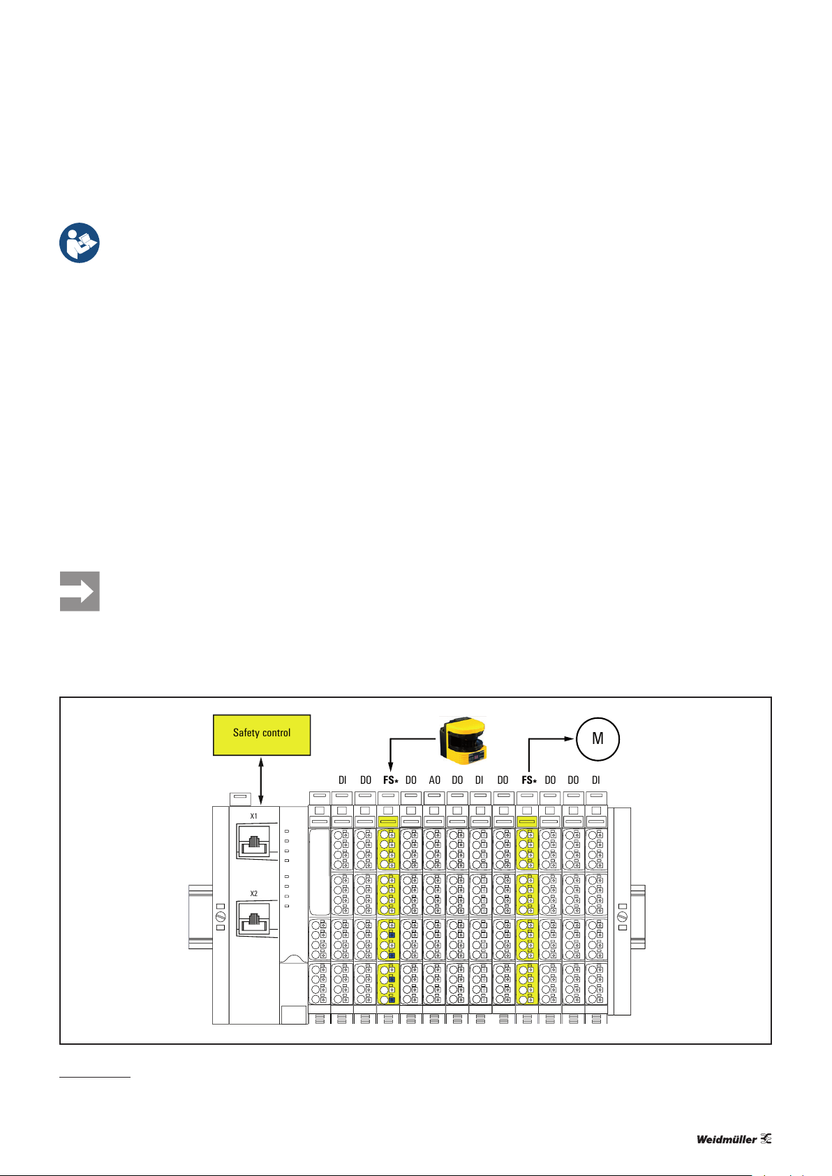
3.1 Sample design
Safe I/O modules can be placed at any position in the
u-remote station. The only exceptions are safety segments
built up from safe power feed modules (s. section 4.1). No
safe I/O module with outputs (UR20-4DI-4DO-PN-FSOE or
UR20-4DI-4DO-PN-FSPS
segment.
The following picture exemplies how to design a u-remote
station with safe I/O modules.
) may be placed within a safety
Example set-up of safe I/O modules (FS*) in a u-remote station
1) Safety over EtherCAT® is a registered trademark and patented technology, licensed by
Beckhoff Automation GmbH, Germany
9u-remote IP20 modules for functional safety manual 1484600000/04/06.2017
Page 10

3 System description of safe I/O modules | Transition diagramm
0
0 2 20104 6 8 12 14 16 18
3
2
1
4
[V]
[mA]
Inputs "off" Inputs "on"
0
0 2 20104 6 8 12 14 16 18
3
2
1
4
[V]
[mA]
Inputs "off" Inputs "on"
3.2 Transition diagramm
Waiting for parameter
Transition diagramm for safe I/O modules
State 1
Unrecoverable fault
Parameter received from safety control
State 3
Fault
State 2
Running
Failure occured
Acknowledgement
by safety control
Failure resolved
State 4
Requesting
acknowledgement
by safety control
3.3 Current-/voltage characteristics of the fail
safe digital inputs
Current-/voltage character istic for P-switching inputs
10 1484600000/04/06.2017u-remote IP20 modules for functional safety manual
Current-/voltage character istic for PN-switching inputs
Page 11

3 System description of safe I/O modules | Registration of safe I/O modules on the safety control
3.4 Registration of safe I/O modules on the
safety control
Safe I/O modules need to get registered on a safety control
using an engineering tool. Via the web server the safe I/O
modules can only be observed but not be parameterised or
forced.
PROFIsafe
For the commissioning of safe I/O modules running with the
PROFIsafe safety protocol you will need the Weidmüller CPD
tool which is available to download on the website. According to the parameter settings this software tool calculates a
check sum, wich will be transferred to the safety control in
Siemens STEP7 and on the TIA portal.
Fail-Safe-over-EtherCAT
For the commissioning of safe I/O modules running with
the Fail safe over EtherCAT safety protocol you will need
TwinCAT as well as a TwinSAFE safety control. The FSOE
modules have been tested using the TwinSAFE-Logic
EL6900 system (Beckhoff) and TwinCAT 2.11.2247
(Beckhoff).
Please use e.g. a ball pen to set the DIP switches
and avoid sharp-edged tools.
With PROFIsafe modules: Make sure that switch-
es without identication marking always remain
in position “Zero”.
Setting the safety address
▶ Before snapping the module onto the DIN rail please set
the safety address according to the project planning via
the DIP switches on the electronic unit.
▶ Snap the module onto the DIN rail and continue the
installation of the u-remote station.
1 0
0
1
2
3
4
5
6
7
8
9
10
11
3.5 Safety address
Before commissioning the safety address (F-address) has to
be set on each safe I/O module using the DIP switches on
the electronic unit. This address is indicated by the project
planning. The safety control transfers the safety address to
the module on each commissioning.
The safety address (decimal) has to be converted into a binary value and then set using the DIP switches .
Decimal/binary conversion table
decimal 2048 1024 512 256 128 64 32 16 8 4 2 1
0 0 0 0 0 0 0 0 0 0 0 1
0 0 0 0 0 0 0 0 0 0 1 0
0 0 0 0 0 0 0 0 0 1 0 0
0 0 0 0 0 0 0 0 1 0 0 0
0 0 0 0 0 0 0 1 0 0 0 0
binary
Example: Address „1234“ is represented by setting
0000010011010010.
0 0 0 0 0 0 1 0 0 0 0 0
0 0 0 0 0 1 0 0 0 0 0 0
0 0 0 0 1 0 0 0 0 0 0 0
0 0 0 1 0 0 0 0 0 0 0 0
0 0 1 0 0 0 0 0 0 0 0 0
0 1 0 0 0 0 0 0 0 0 0 0
1 0 0 0 0 0 0 0 0 0 0 0
1234 0 1 0 0 1 1 0 1 0 0 1 0
11
9
7
10
8
1
5
3
0
4
2
6
1 0
0000010011010010
DIP switches for set ting the safety address on a PROFIsafe module (example setting: 1234)
Changing the safety address
To change the safety address after the module has been assigned to the control please act as follows (with V2 modules
start with step5):
1. Pull out the electronic unit.
2. Set all DIP switches to position „Zero“.
3. Slide the electronic unit back into the module and turn on
the module/station.
4. Please wait until the status LED of the module lights alternating red and green (3 s green, 1 s red).
Only now the old safety address has been deleted and the
new one can be set.
5. Pull out the electronic unit again and set the new safety
address.
6. Slide the electronic unit back into the module and turn on
the module/station.
The status LED of the module lights green and the new safety address will be displayed on the web server.
11u-remote IP20 modules for functional safety manual 1484600000/04/06.2017
Page 12

3 System description of safe I/O modules | External circuitry of a PN/P output pair
1
2
3
4
1
2
3
4
DO (PN)
24 V DC
DO (P)
DO (PN)
DO (P)
1
2
3.6 External circuitry of a PN/P output pair
All information in this section refer to the ZVEI position paper
CB24I (Edition 2.0).
The outputs of the module can be circuited as follows.
Options for the external circuitry of the outputs
Circuit diagram Parameterisation
2 x single-channel, P-switching
1
2 2 x single-channel, rst channel N-switching
3 dual-channel, rst channel N-switching
Examples 1 and 2
2 x single-channel, P-switching or dual-channel, P-switching
The outputs in circuit diagram1 correspond to the typeC
source.
or
dual-channel, P-switching
DO (PN)
1
DO (P)
1
2
3
4
Example 3
Dual-channel, rst channel N-switching
The outputs correspond with the typeD source.
DO (PN)
3
DO (P)
External dual-channel circuitr y of the outputs
Test pulse class Parameterisable per test pulse duration
Test pulse duration Depending on the parameterisation 0.5 ... 10ms
Test pulse intervall 200ms
Rated current 0.5A (as per EN61131-2)
Depending on the parameterisation and the load
current. With test pulses enabled the output current
Capacitive load
must be reduced to <10V within one millisecond.
With test pulses disabled (only possible with V2
modules) the connected capacity must not exceed
250µF.
Inductive load
Lamp load
As per EN61131-2 for 0.5Aoutputs, maximum
leakage current in state OFF: 100µA
When using a lamp load the test pulses must be
enabled (V2 modules only).
1
2
3
4
DO (PN)
2
DO (P)
External circuitr y of the outputs
1
2
3
4
24 V DC
Test pulse class Parameterisable per test pulse duration
Test pulse duration Depending on the parameterisation 0.5 ... 10ms
Test pulse intervall 200ms
Rated current 0.5A (as per EN61131-2)
Capacitive load
Depending on the parameterisation and the load
current. With test pulses enabled the output current
must be reduced to <10V within one millisecond.
With test pulses disabled (only possible with V2
modules) the connected capacity must not exceed
250µF.
Inductive load
Lamp load
As per EN61131-2 for 0.5Aoutputs, maximum
leakage current in state OFF: 100µA
When using a lamp load the test pulses must be
enabled (V2 modules only).
3.7 Operating with and without own test
pulses
All information in this section refer to the ZVEI position paper
CB24I (Edition 2.0).
The parameter settings allow to enable test pulses for the
inputs of the safe I/O modules. These test pulses are generated and analysed by the module. Thus the highest safety
levels can be achieved (see technical data). The test pulse
duration is determined by the input delay.
When operating without test pulses AUX-OX and AUX-OY
can be used as outputs for the supply voltage. The active
output signal includes test pulses, the length of which is pa-
rameterisable between 0.5ms and 10ms. With V2 modules
these test pulses can be disabled.
Please regard the notes for parameter settings
whenever you disable the test pulses (see module
descriptions in chapter5).
12 1484600000/04/06.2017u-remote IP20 modules for functional safety manual
Page 13

3 System description of safe I/O modules | Operating with and without own test pulses
Examples for operating with test pulses
DI X (PN)
AUX-O X
AUX-O Y
DI Y (P)
Connecting example type A sink
Input current 2.5mA typ. (acc. to Type3 as per EN61131-2)
Output voltage:
AUX-OX, P-switching 22V typ. (Supply voltage minus 2V)
AUX-OX, N-switching 0V
AUX-OY Supply voltage 24V typ.
Input capacity 10nF typ.
DI X (PN)
AUX-O X
AUX-O Y
DI Y (P)
1
2
3
4
+24 V DC
Safety relay
1
2
3
4
For the operation with test pulses the V2modules can be
installed either with three or with four wires:
DI X
AUX-O X
AUX-O Y
DI Y
Operation with own test pulses, 4-wire installation
DI X
AUX-O X
AUX-O Y
DI Y
Operation with own test pulses, 3-wire installation
1
2
3
4
1
2
3
4
Examples for operating without test pulses
The following parameter settings are needed if an external
device is connected that generates test pulses by its own:
V1modules: test pulse “disabled“
V2modules: test pulse “external”.
Connecting example type B sink
Test pulse delay Depending on the parameterisation
Test pulse duration
0.5 to 10ms; depending on the parameterised input
delay
Test pulse intervall 1200ms
Input capacity 10nF typ.
Antivalent circuits are possible with V2 modules only.
DI X (PN)
AUX-O X
AUX-O Y
DI Y (P)
Connecting example with antivalent input circuit (V2 only)
1
2
3
4
DI X (PN)
AUX-O X
AUX-O Y
DI Y (P)
Connecting example for oper ation without own test pulses, typeC sink, class1
1
2
GND
3
+24 V DC
4
OSSD
Safety
device
Test pulse duration Max. 1ms
Test pulse intervall Min. 0
Input resistance Min. 7.2kOhm (at 18V)
Input capacity Max. 10nF typ.
Input inductivity Max. 1mH
13u-remote IP20 modules for functional safety manual 1484600000/04/06.2017
Page 14

3 System description of safe I/O modules | Processing time
DI X (PN)
AUX-O X
AUX-O Y
DI Y (P)
DI X (PN)
AUX-O X
AUX-O Y
DI Y (P)
DI X
AUX-O X
AUX-O Y
DI Y
Example for the operat ion without own test pulses
1
2
3
4
1
2
3
4
1
2
GND
3
+24 V DC
4
+24 V DC
GND module
+24 V DC
3.8 Processing time
The response time for each input or output of a safe I/O
module is <10ms. The processing time of a signal within the
safety chain can be calculated as follows:
Input delay (parameterised)
+ Response time input (<10 ms)
+ Response time output (<10 ms)
+ Data transfer from and to the PLC
+ PLC computing time
= Processing time
In the event that the module shall be used as
typeA source with disabled test pulses the DIX
input must be parameterised N-switching.
DI X (N)
AUX-O X
AUX-O Y
DI Y (P)
Operation without own test pulses, typeA source with N- switching DIX
1
2
3
4
14 1484600000/04/06.2017u-remote IP20 modules for functional safety manual
Page 15

4 System description of safe power-feed modules
4 System description of safe power-feed modules
This chapter contains product-specic information and notes about the use of safe power-feed
modules. Please also observe the system description in the u-remote manual document umber
1432790000)
The PF-O-xDI-SIL modules are controlled using contact-based safety transducers and/or safety transducers with
OSSD outputs.
Each PF-O-xDI-SIL module safely switches off all following modules that are supplied by the output current path
and thus creates a safety segment. A survey of the switchable modules is shown at the end of this section. The safety
segment extends either to the next PF-O module or to the
end of the station. A safety-related input circuit together with
pulsed inputs is used for detecting broken wires and short
circuits.
Three types of safe power-feed modules are available in the
u-remote system:
– UR20-PF-O-1DI-SIL (one safe input)
– UR20-PF-O-2DI-SIL (two safe inputs)
– UR20-PF-O-2DI-DELAY-SIL (two safe inputs, delayed
switching off possible)
Thereby the following safety functions can be implemented:
– Up to two dual-channel safety circuits (AND linked), e.g.
for emergency stop switch, safety door contacts and
safety light curtains
– A range of output modules within a u-remote station is
safely supplied with power via the switched 24VSafe
output.
– PF-O-xDI-SIL modules can be cascaded.
Safety function
The safety function of the safe power-feed modules is
that the safe output “24VSafe” is being switched according to the informations of the inputs (Type3 according to
EN61131-2, N-switching respectively). The safe status is
“24V switched off” (current path for outputs and the output
“24V Safe” is switched off).
Safe power-feed module UR20-PF -O-1DI-SIL
Safe power-feed module UR20-PF -O-2DI-SIL and UR20-PF-O -2DI-DELAY-SIL
15u-remote IP20 modules for functional safety manual 1484600000/04/06.2017
Page 16
4 System description of safe power-feed modules | Sample design
DI DI DO DIDODODO DO
PF-O
SIL
PF-OAO DO
FB
U
OUT
24 V Safe
U
OUT
24 V
U
IN
24 V
24 V
24 V
24 V
1
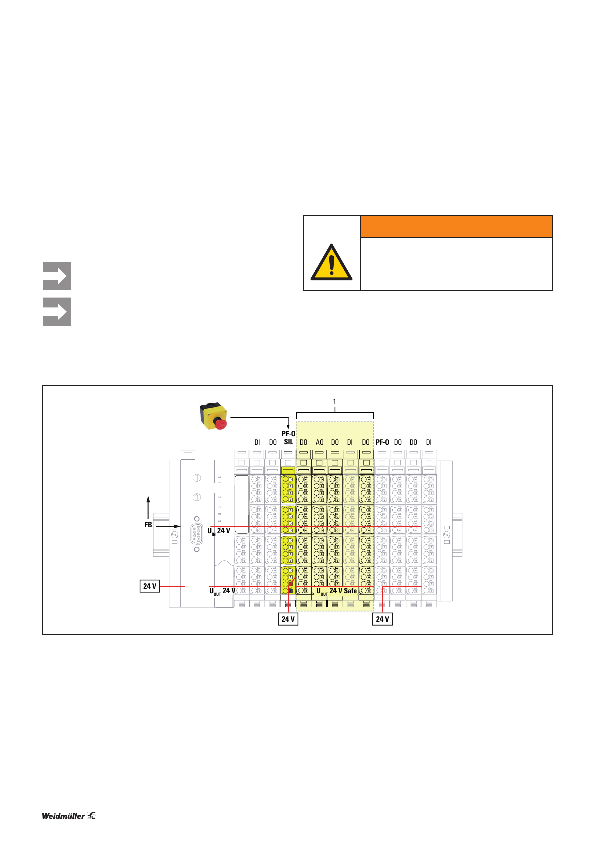
4.1 Sample design
The following picture exemplies how to design a safety segment using a safe power-feed module. All output modules
arranged within the safety segment will be switched safely.
Input modules can be arranged within the safety segment,
only they do not fulll any safety function and are not inuenced by the PF-O-xDI-SIL module.
Safe I/O modules with outputs may not be positioned within a safety segment.
For detailed planning please also observe the
notes in the section „Conguration“.
To switch the 24VSafe voltage back on, either an automatic
or a manual start can be selected.
– Automatic start: the safe output current path is switched
on immediately after resetting the safety circuit(s).
WARNING
Possible danger to life!
The option “Automatic start” might only be
used, after a risk analysis has shown that the
application is suitable.
– Manual start: the output current path is only switched on
again if the start button has been held down for 0.5 to
2seconds.
Example set-up of a saf ety segment (1) with PF-O-xDI-SIL
16 1484600000/04/06.2017u-remote IP20 modules for functional safety manual
Page 17

4.2 Transition diagramm
4 System description of safe power-feed modules | Transition diagramm
State 1
Idle
24 VSafe off
SS1 off
Delay time
expired
State 3
Wait for power off
24 VSafe on
SS1 off
Manual start mode or autostart mode after power on
Safety circuit inactive
no delay
1) Both channels of a safety circuit must get active within a discrepancy time of 0.5s max.
2) The 24 V Safe output remains on until delay time is expired.
3) At least one channel of the safety circuit.
Safety circuit active
Safety circuit inactive
3
Safety circuit active
Autostart mode
Safety circuit inactive
delay
1
3
2
Safety circuit active
Manual start mode
Autostart mode, not after power on
Safety circuit active
1
3
State 2
Wait for start
24 VSafe off
SS1 off
Manual start
key pressed
1
State 4
Running
24 VSafe on
SS1 on
Transition diagramm of safe power-f eed modules
With the delay SIL module (UR20-PF-O-2DI-DELAY-SIL)
switching off can be delayed by a dened time so that,
for example, a machine can be shut down in a controlled
manner. The delay time can be set in four steps between
0 and 60 seconds (corresponds to stop category 1 as per
EN60204).
17u-remote IP20 modules for functional safety manual 1484600000/04/06.2017
Page 18
4 System description of safe power-feed modules | Modules switchable by PF-O-xDI-SIL
4.3 Modules switchable by PF-O-xDI-SIL
Safely switchable output modules:
– UR20-4DO-P
– UR20-4DO-P-2A
– UR20-4DO-PN-2A
– UR20-8DO-P
– UR20-8DO-P-2W-HD
– UR20-16DO-P
– UR20-16DO-P-PLC-INT
– UR20-4DO-N
– UR20-4DO-N-2A
– UR20-8DO-N
– UR20-2PWM-PN-0.5A
– UR20-2PWM-PN-2A
– UR20-4AO-UI-16
– UR20-4AO-UI-16-HD
– UR20-4AO-UI-16-DIAG
– UR20-4AO-UI-16-DIAG-HD
In case a N-switching output module is positioned within a
safety segment the connected load needs to be switched
against +24V Safe.
The relay output modules UR20-4RO-CO-255 and UR204RO-SSR-255 are not safely switchable, therefore they must
not switch any safety function.
The digital counter module UR20-1CNT-1DO-100 will not be
switched since it is supplied via the input current path.
4.4 Conguration
A PF-O-xDI-SIL module can be positioned anywhere in
the u-remote station. Multiple PF-O-xDI-SIL modules
and thus safety segments can be set up in a single station.
When planning a u-remote station with PF-O-xDI-SIL
modules, the following requirements must be met:
– The overall current consumption from the system current
path of all switchable modules within a safety segment
must be lower than 100mA (see table in section4.5).
– Each safety segment might include at most 12 switcha-
ble modules.
– The switch-off delay time for the safe input channels
within a safety circuit is 500ms ± 10ms.
– The load output is not designed for either inductive or
capacitive loads.
– The feed-in of the PF-O-xDI-SIL module must be
safeguarded with a 8-A super fast fuse.
– A SELV/PELV power supply must be used.
– The safely shut-off systems/applications must get their
power exclusively from the safe feed-in module
PF-O-xDI-SIL. Likewise, it must not be possible to
feed external energy into the safety segment elsewhere.
– Relay modules can be located within a safety segment,
however their outputs cannot be safely shut off in case of
a malfunction.
– At the SS1 output of the UR20-PF-O-2DI-DELAY-SIL, only
systems/equipment that do not feed any power back into
the system in the event of a malfunction can be connected.
– Any external short circuits in the wiring of the safe output
must be avoided.
– Fault exclusion as per EN ISO13849-2 must be provided.
4.5 Switch-off delay time
The turn-off time of a PF-O-xDI-SIL module is 20ms,
caused by the hardware and rmware delay time. The time
required until the output voltage even of the last switchable
module of a safety segment is below 5V, can be calculated
as follows:
Turn-off time of a PF-O-xDI-SIL module
+ Sum of all modules’ hardware delay
= Switch off delay [ms]
Switch-off delay and current consumption
Hardware delay [ms] Current consumption
[mA]
from I
SYS
UR20-4DO-P
UR20-4DO-P-2A
UR20-4DO-PN-2A
UR20-8DO-P
UR20-8DO-P-2W-HD
UR20-16DO-P
UR20-16DO-P-PLC-INT
UR20-4DO-N
UR20-4DO-N-2A
UR20-2PWM-PN-0.5A
UR20-2PWM-PN-2A
UR20-4AO-UI-16
UR20-4AO-UI-16-HD
UR20-4AO-UI-16-DIAG
UR20-4AO-UI-16-DIAG-HD
*The delay time is always 150ms, irrespective of the amout of these modules.
2 8
2 8
3 15
1 15
1 15
1 10
1 10
2 8
2 8
5 10
5 10
150* 10
150* 10
150* 10
150* 10
18 1484600000/04/06.2017u-remote IP20 modules for functional safety manual
Page 19
4 System description of safe power-feed modules | Operation with and without test pulses
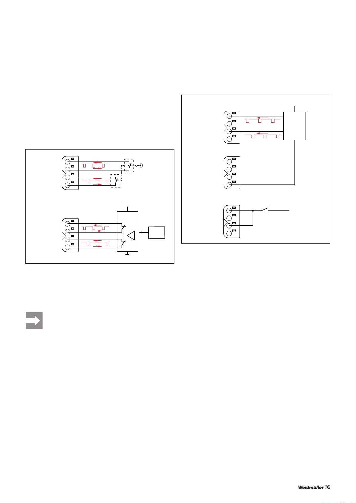
4.6 Operation with and without test pulses
The safe input circuits are designed to connect passive dual
channel switching devices. Each input channel is provided
with pulsed voltage the test pulses of which are analysed.
Therefore the highest safety levels can be achieved (see technical data).
S11 / S31
S12 / S32
S21 / S41
S22 / S42
S11 / S31
S12 / S32
S21 / S41
S22 / S42
Exemplary operation w ith test pulses
1
2
3
4
+24 V DC
Safety relay
1
2
3
4
Sensor
+24 V DC
S11 / S31
S12 / S32
S21 / S41
S22 / S42
1
2
1
3
4
Safety relay
with
OSSD
outputs
...
1
2
4
3
GND
S11 / S31
S12 / S32
S21 / S41
S22 / S42
Exemplary operation of the UR20-PF-O-2DI-DELAY-SIL without test pulses
Test pulses can be enabled or disabled using the DIP-switches of the module.
4
1
2
3
4
+24 V DC
The safe power-feed module UR20-PF-O-2DI-DELAY-SIL
might also be operated without test pulses. This is mandatory whenever an external device gernerating own test pulses
is connected.
When using switching devices generating own
test pulses please regard that low level with a
duration of more than 2ms will be detected as an
opening of the safety circuit.
19u-remote IP20 modules for functional safety manual 1484600000/04/06.2017
Page 20

20 1484600000/04/06.2017u-remote IP20 modules for functional safety manual
Page 21
5 Detailed descriptions of safe modules
5.1 General technical data
5 Detailed descriptions of safe modules | General technical data
Type of connection
Line connection cross-section
Dimensions
Protection class (DIN EN 60529)
Flammability rating UL94
Temperature data
Humidity
Air pressure
Vibration resistance
Shock resistance
Potential isolation
“PUSH IN”
Single-wired 0.14 – 1.5mm2 (AWG 16 – 26)
2
Fine-wired 0.14 – 1.5mm
Height 120mm (128mm with release lever)
Width 11.5mm
Depth 76.0mm
IP20
V-0
Operation -20°C to +60°C
Storage, transport -40°C to +85°C
Operation, storage, transport 5 % to 95 %, non-condensing as per IEC 61131-2
Operation ≥ 795 hPa (altitude ≤ 2000m) as per IEC 61131-2
Storage, transport ≥ 700 hPa (altitude ≤ 3000m) as per IEC 61131-2
5Hz ≤ f ≤ 8.4Hz: 3.5-mm amplitude as per IEC 60068-2-6
8.4Hz ≤ f ≤ 150Hz: 1-g acceleration as per IEC 60068-2-6
15 g for 11 ms, half sinewave, as per IEC 60068-2-27
Test voltage Max. 28.8 V within a channel
500V DC eld/system
Pollution severity level 2
(AWG 16 – 26)
Overvoltage category II
Approvals and Standards
1)
Unless otherwise noted within the product-specific technical data.
1)
cULus UL 508 pending
Potentially explosive atmosphere Zone 2 ATEX Directive 2014/34/EU
EMC EN 61000 (Partial standards as per requirements of IEC61131-2)
Explosion protection EN 60079-0:2009 and EN60079-15:2010
PLC IEC 61131-2
FS DINENISO13849-1, IEC61508, IEC62061
You can nd all product-specic technical data in the corresponding product description.
21u-remote IP20 modules for functional safety manual 1484600000/04/06.2017
Page 22

5 Detailed descriptions of safe modules | Data width dependent on the coupler used
5.2 Data width dependent on the coupler used
Data width
Order No. Module Configuration Parameter Diagnostics Process data
Input Output
Bytes Bytes Bytes Bytes B ytes
UR20-FBC-PB-DP
1334870000 UR20-FBC-PB-DP — 8 47 — —
1335030000 UR20-PF-O-1DI-SIL 3 — 47 4 —
1335040000 UR20-PF-O-2DI-DELAY-SIL 3 — 47 4 —
1335050000 UR20-PF-O-2DI-SIL 3 — 47 4 —
1335060000 UR20-4DI-4DO-PN-FSPS 7 26 47 5 5
1335070000 UR20-8DI-PN-FSPS 7 26 47 5 5
2464570000 UR20-4DI-4DO-PN-FSPS-V2 7 30 47 5 5
2464590000 UR20-8DI-PN-FSPS-V2 7 35 47 5 5
Max. data (in byte) 244 244 244 244 244
UR20-FBC-PN-IRT
1334880000 UR20-FBC-PN-IRT 4 10 47 4 4
1335030000 UR20-PF-O-1DI-SIL 4 — 47 5 1
1335040000 UR20-PF-O-2DI-DELAY-SIL 4 — 47 5 1
1335050000 UR20-PF-O-2DI-SIL 4 — 47 5 1
1335060000 UR20-4DI-4DO-PN-FSPS 4 23 47 6 6
1335070000 UR20-8DI-PN-FSPS 4 23 47 6 6
2464570000 UR20-4DI-4DO-PN-FSPS-V2 4 27 47 6 6
2464590000 UR20-8DI-PN-FSPS-V2 4 32 47 6 6
Max. data (in byte) 260 4362 1408 512 512
UR20-FBC-EC
1334910000 UR20-FBC-EC 256 4096 3328 1024 1024
1335030000 UR20-PF-O-1DI-SIL 4 — 47 4 —
1335040000 UR20-PF-O-2DI-DELAY-SIL 4 — 47 4 —
1335050000 UR20-PF-O-2DI-SIL 4 — 47 4 —
1529800000 UR20-8DI-PN-FSOE 4 5 47 6 6
1529780000 UR20-4DI-4DO-PN-FSOE 4 5 47 6 6
2464580000 UR20-4DI-4DO-PN-FSOE-V2 4 9 47 6 6
2464600000 UR20-8DI-PN-FSOE-V2 4 14 47 6 6
Max. data (in byte) 1514 pro telegramm + CoE 1514 pro telegramm + CoE 1514 pro telegramm + CoE 1024 1024
UR20-FBC-EIP
1334910000 UR20-FBC-EC 8 — — 2/10 2/10
1335030000 UR20-PF-O-1DI-SIL 4 — 47 4 —
1335040000 UR20-PF-O-2DI-DELAY-SIL 4 — 47 4 —
1335050000 UR20-PF-O-2DI-SIL 4 — 47 4 —
Max. data (in byte) 264 — — 496/504 496/504
22 1484600000/04/06.2017u-remote IP20 modules for functional safety manual
Page 23

5 Detailed descriptions of safe modules | Data width dependent on the coupler used
Data width
Order No. Module Configuration Parameter Diagnostics Process data
Input Output
Bytes Bytes Bytes Bytes B ytes
UR20-FBC-DN
1334900000 UR20-FBC-DN - 11 47 2/10 2/10
1335030000 UR20-PF-O-1DI-SIL 4 — 47 4 —
1335040000 UR20-PF-O-2DI-DELAY-SIL 4 — 47 4 —
1335050000 UR20-PF-O-2DI-SIL 4 — 47 4 —
Max. data (in byte) 264 400 47 496/504 496/504
UR20-FBC-CAN
1334890000 UR20-FBC-CAN — 47 — —
1335030000 UR20-PF-O-1DI-SIL 2 47 4 —
1335040000 UR20-PF-O-2DI-DELAY-SIL 2 47 4 —
1335050000 UR20-PF-O-2DI-SIL 2 47 4 —
Max. data (in byte) 128 — 3055 256 256
UR20-FBC-MOD-TCP
Order No. Module Process data
Input Output
Bytes Bytes
1335030000 UR20-PF-O-1DI-SIL 4 Bytes —
1335040000 UR20-PF-O-2DI-DELAY-SIL 4 Bytes —
1335050000 UR20-PF-O-2DI-SIL 4 Bytes —
The register structure for UR20-FBC-MOD-TCP see u-remote manual, section5.4.
23u-remote IP20 modules for functional safety manual 1484600000/04/06.2017
Page 24
5 Detailed descriptions of safe modules | Digital in- and output module UR20-4DI-4DO-PN-FSOE, UR20-4DI-4DO-PN-FSOE-V2
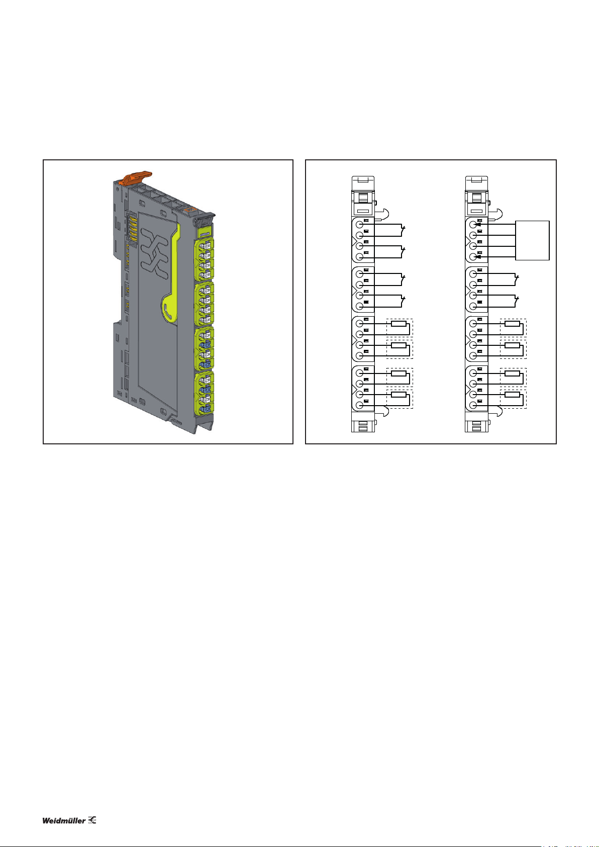
5.3 Digital in- and output module UR20-4DI-4DO-PN-FSOE, UR20-4DI-4DO-PN-FSOE-V2
Digital in- and output module UR20-4DI-4DO-PN-FSOE (Best.-Nr. 1529780000),
UR20-4DI-4DO-PN-FSOE-V2 (Bes t.-Nr. 2464580000)
The digital input and output module UR20-4DI-4DO-PN-FSOE
or UR20-4DI-4DO-PN-FSOE-V2 is a safe I/O module for
the Fail-Safe-over-EtherCAT (FSoE) protocol. Each module
provides four digital inputs and outputs respectively, it can
detect up to four binary control signals and control up to four
actuators each with a maximum of 0.5A. Two inputs and
outputs respectively can be parameterised P- or N-switching.
Sensors can be connected to connectors 1 and 2 using a
2-wire, 3-wire or 4-wire connection. In the event that the
available supply current of 0.8A per plug will not sufce, the
sensor supply must be realised using the auxiliary outputs
of another module (e.g. potential distribution module) within
the same power segment.
Actuators can be connected to connectors 3 and 4 using a
2-wire connection. A status LED is assigned to each channel.
The module electronics supply the inputs as well as the outputs with power from the output current path (I
OUT
).
A test pulse check of the inputs can be parameterised as a
cross-circuit detection between input singal and supply voltage, between different input signals or other signals. Thus an
input gets active only when the signal of the dedicated auxiliary output is pending. The test pulses must be disabled, if a
safety relay with OSSD outputs generating own test pulses is
connected.
4DI·4DO
DI 0 (PN)
AUX-O 0
AUX-O 1
DI 1 (P)
DI 2 (PN)
AUX-O 2
AUX-O 3
DI 3 (P)
DO 0 (PN)
GND
DO 1 (P)
GND
DO 2 (PN)
GND
DO 3 (P)
GND
Connection diagram UR20-4DI-4DO -PN-FSOE, UR20-4DI-4DO-PN-FSOE-V2 (Examples)
1
2
1
3
4
1
2
2
3
4
1
2
3
3
4
1
2
4
3
4
DI 0 (PN)
AUX-O 0
AUX-O 1
DI 2 (PN)
AUX-O 2
AUX-O 3
DO 0 (PN)
DO 1 (P)
DO 2 (PN)
DO 3 (P)
DI 1 (P)
DI 3 (P)
GND
GND
GND
GND
1
2
3
4
4DI·4DO
1
2
3
4
1
2
3
4
1
2
3
4
1
2
3
4
GND
24 V DC
Safety relay
with OSSD
outputs
With the variant1 module the active output signal always
includes test pulses for the purpose of cross-circuit and error
detection. The test pulse duration can be parameterised.
A safety sensor that is being connected in a dual channel
mode must allocate the PN and the P-input of one connector
(safety architecture of category 4 acc. to DINENISO13849).
The external circuitry of a PN/P output pair is described in
Chapter3.
24 1484600000/04/06.2017u-remote IP20 modules for functional safety manual
Page 25
4DI-4DO
System
bus
U
SYS
U
IN
U
OUT
µC
µC
µC
24 V DC
GND
GND
DOx
4x
4x
2x
Config.
switch
DC
DC
1
2
3
4
DO 0 (PN)
GND
DO 1 (P)
GND
DI 0 (PN)
AUX-O 0
AUX-O 1
DI 1 (P)
DI 2 (PN)
AUX-O 2
AUX-O 3
DI 3 (P)
DO 2 (PN)
GND
DO 3 (P)
GND
Type 3
DI 0
•
•
DI 3
DO 0
•
•
DO 3
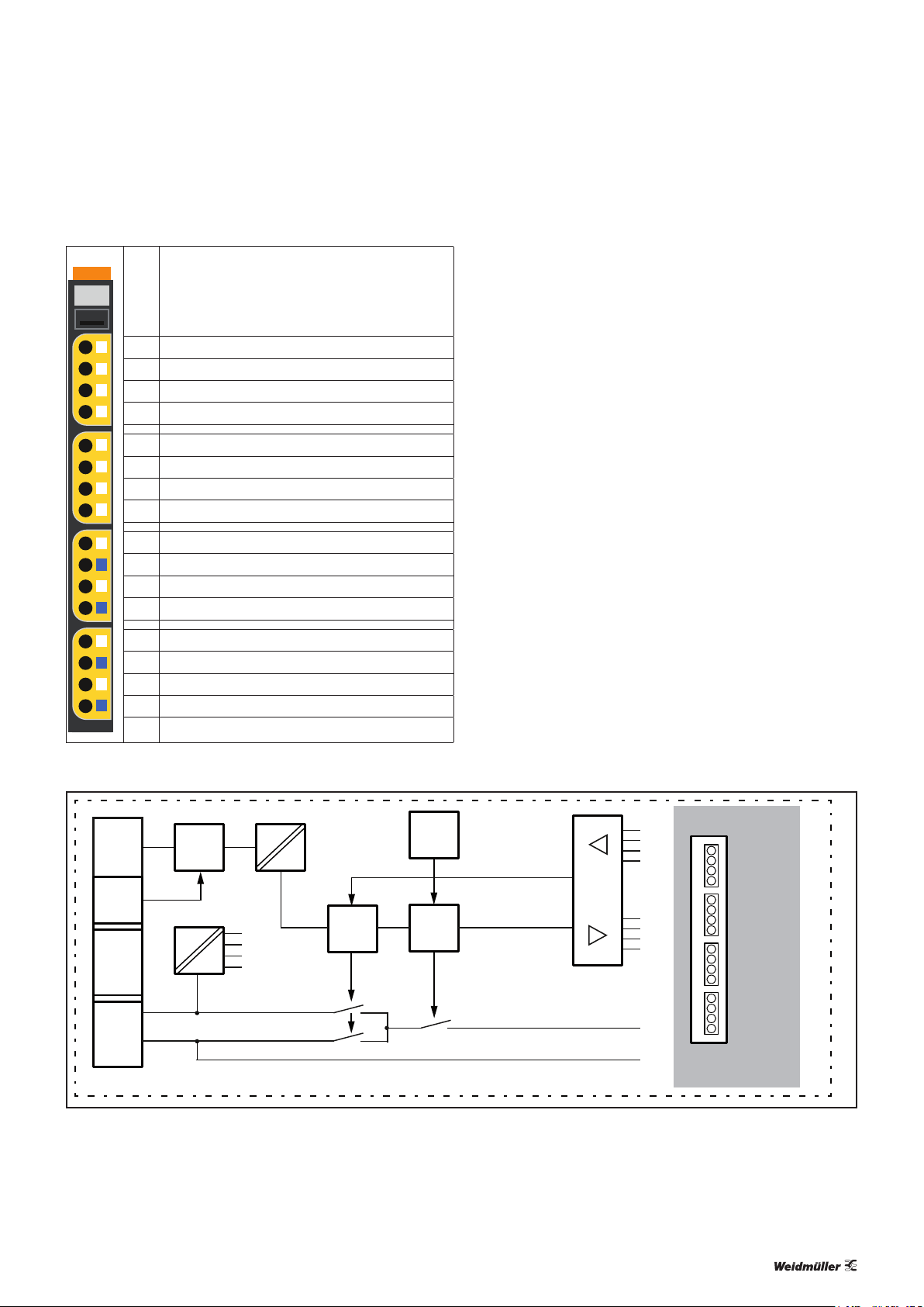
5 Detailed descriptions of safe modules | Digital in- and output module UR20-4DI-4DO-PN-FSOE, UR20-4DI-4DO-PN-FSOE-V2
Module status LED
Green: Communication on system bus
3s green/1s red: Waiting for parameters
1s green/1s red: Waiting for acknowledgement by safety control
Red: Collective error diagnostic
1.1 Yellow: Input 0 active
1.3 Red: Error sensor supply or input 0 or input 1
1.4 Yellow: Input 1 active
2.1 Yellow: Input 2 active
2.3 Red: Error sensor supply or input 2 or input 3
2.4 Yellow: Input 3 active
3.1 Yellow: Output 0 active
3.2 Red: Error output 0
3.3 Yellow: Output 1 active
3.4 Red: Error output 1
4.1 Yellow: Output 2 active
4.2 Red: Error output 2
4.3 Yellow: Output 3 active
4.4 Red: Error output 3
LED indicators UR20-4DI-4DO -PN-FSOE, UR20-4DI-4DO-PN-FSOE-V2, error messages see Chapt er7
Block diagram UR20-4DI-4DO-PN-FSOE , UR20-4DI-4DO -PN-FSOE-V2
25u-remote IP20 modules for functional safety manual 1484600000/04/06.2017
Page 26

5 Detailed descriptions of safe modules | Digital in- and output module UR20-4DI-4DO-PN-FSOE, UR20-4DI-4DO-PN-FSOE-V2
Technical data UR20-4DI-4DO-PN-FSOE (Order No. 1529780000), UR20-4DI-4DO-PN-FSOE-V2 (OrderNo.2464580000)
System data
Data
Interface
System bus transfer rate
Process and diagnostic data depend on the coupler used, see section 5.2
u-remote system bus
48 Mbps
Safety-related data according to ENISO13849-1 (Regard the entire safety chain!)
Achievable safety level inputs
Achievable safety level outputs
Diagnostic Coverage (DC) inputs
Diagnostic Coverage (DC) outputs
MTTFD (Mean Time To Failure dangerous) inputs
MTTFD (Mean Time To Failure dangerous) outputs
Single-channel circuit 1oo1
Dual-channel circuit 1oo2
Single-channel circuit 1oo1
Dual-channel circuit 1oo2
Dual-channel circuit 1oo2 99%
PLd, Categorie2
PLe, Categorie4
PLe, Categorie4
90%
99%
> 100 Years (840 Years)
> 100 Years (279 Years)
Safety-related data according to EN62061 (Regard the entire safety chain!)
Achievable safety level inputs
Single-channel circuit 1oo1
Dual-channel circuit 1oo2
Achievable safety level outputs
PFH (Probability of Failure per hour in 1/h) inputs
Single-channel circuit 1oo1
Dual-channel circuit 1oo2
PFH (Probability of Failure per hour in 1/h) outputs
Fault reaction time
Single-channel circuit 1oo1 5s
Safety-related data according to EN61508 (Regard the entire safety chain!)
Achievable safety level inputs
Single-channel circuit 1oo1
Dual-channel circuit 1oo2
Achievable safety level outputs
PFH (Probability of Failure per hour in 1/h) inputs
Single-channel circuit 1oo1
Dual-channel circuit 1oo2
PFH (Probability of Failure per hour in 1/h) outputs
PFD (Probability of Failure per Demand) inputs
Single-channel circuit 1oo1
Dual-channel circuit 1oo2
PFD (Probability of Failure per Demand) outputs
HFT (Hardware Failure Tolerance) inputs
Single-channel circuit 1oo1
Dual-channel circuit 1oo2
HFT (Hardware Failure Tolerance) outputs
SFF (Safe Failure Fraction) inputs and outputs
Presumed lifecycle time
Prooftest intervall
Classification acc. to EN61508-2:2010
98%
20 Years
No prooftest needed within the life cycle
Type B
SILCL2
SILCL3
SILCL3
-8
10
2,94*10
5,56*10
SIL2
SIL3
SIL3
-8
10
2,17*10
2,17*10
8,77*10
1,85*10
1,85*10
0
1
1
-9
-9
-10
-10
-4
-5
-5
26 1484600000/04/06.2017u-remote IP20 modules for functional safety manual
Page 27

5 Detailed descriptions of safe modules | Digital in- and output module UR20-4DI-4DO-PN-FSOE, UR20-4DI-4DO-PN-FSOE-V2
Technical data UR20-4DI-4DO-PN-FSOE (Order No. 1529780000), UR20-4DI-4DO-PN-FSOE-V2 (OrderNo.2464580000)
Inputs
Number
Input Type
Input filter
Response time
Low input voltage
High input voltage
Sensor supply
Sensor connection
Reverse polarity protection
Module diagnosis
Individual channel diagnosis
1) Minimum rate of change in transition range: 1V/s. Deviating from EN61131-2 the following applies for PN-inputs in P-switching mode:The input will be read “inactive” if the input
voltage considerably exceeds the module supply voltage.
4, two of which are parameterisable P- or N-switching
Type1 and 31) as per IEC 61131-2 (N-switching based on the standard)
Input delay adjustable from 1 to 100ms
<10ms
P-switching: < 5 V; N-switching: > -5 V to +24 V
P-switching: >11 V; N-switching: < -11 V to +24 V
Max. 0.8A per plug, total max. 1.6A
2-wire, 3-wire, 4-wire
yes
yes
yes
Outputs
Number
Type of load
Response time
Output current
4, two of which are parameterisable P- or N-switching
Ohmic, inductive, lament lamp load
<10 ms
per channel 0.002 to 0.5A
per module max. 2A
Breaking energy (inductive)
Switching frequency
Actuator connection
Short-circuit-proof
Protective circuit
Response time of the current limiting circuit
Module diagnosis
Individual channel diagnosis
Safe status
150mJ/channel
Resistive load (min. 47 Ω) 10Hz
Inductive load (DC 13) 0.2Hz without free-wheeling diode
10Hz with suitable free-wheeling diode
Filament lamp load (12W) 10Hz
2-wire
yes
Constant current with thermal switch-off
approx. 1,1A (P-switching), approx. 3,5A (N-switching)
< 100µs
yes
yes
P-switching: < 5V, < 2mA
N-switching: > -2mA (referred to +24VDC)
27u-remote IP20 modules for functional safety manual 1484600000/04/06.2017
Page 28
5 Detailed descriptions of safe modules | Digital in- and output module UR20-4DI-4DO-PN-FSOE, UR20-4DI-4DO-PN-FSOE-V2
Technical data UR20-4DI-4DO-PN-FSOE (Order No. 1529780000), UR20-4DI-4DO-PN-FSOE-V2 (OrderNo.2464580000)
Supply
Supply voltage
Current consumption from system current path I
Current consumption from output current path I
SYS
OUT
24V DC +20 %/-15 %
8mA
20mA + output current + current consumption from the auxiliary outputs
General data
Weight (operational status)
93 g
Additional general data, see Section 5.1.
Overview of the editable parameters1) UR20-4DI-4DO-PN-FSOE
Channel Description Options Default
0 ... 1 Input delay 1 ms (0) / 3ms (1) / 10ms (2) / 100ms (3) 1ms
0 ... 1 Test pulse disabled (0) / enabled (1) disabled
0 Input polarity P-switching (0) / N-switching (1) P-switching
0 + 1 Input dual channel mode (inputs 0 + 1) single channel (0) / dual channel (1) single channel
0 + 1 Discrepancy time 5 ms (0) / 50ms (1) / 2s (2) / 30s (3) 5ms
2 ... 3 Input delay 1 ms (0) / 3ms (1) / 10ms (2) / 100ms (3) 1ms
2 ... 3 Test pulse disabled (0) / enabled (1) disabled
2 Input polarity P-switching (0) / N-switching (1) P-switching
2 + 3 Input dual channel mode (inputs 2 + 3) single channel (0) / dual channel (1) single channel
2 + 3 Discrepancy time 5 ms (0) / 50ms (1) / 2s (2) / 30s (3) 5ms
4 ... 5 Output test pulse duration (output 0 ... 1) 0.5 ms (0) / 1ms (1) / 3ms (2) / 10ms (3) 0.5ms
4 Output polarity P-switching (0) / N-switching (1) P-switching
4 + 5 Output dual channel mode (outputs 0 + 1) single channel (0) / dual channel (1) single channel
6 ... 7 Output test pulse duration (output 2 ... 3) 0.5 ms (0) / 1ms (1) / 3ms (2) / 10ms (3) 0.5ms
6 Output polarity P-switching (0) / N-switching (1) P-switching
6 + 7 Output dual channel mode (outputs 2 + 3) single channel (0) / dual channel (1) single channel
1) Please regard the notes for parameter settings.
Overview of the editable parameters1) UR20-4DI-4DO-PN-FSOE-V2
Channel Description Options Default
0 Input delay 1 ms (0) / 3ms (1) / 10ms (2) / 100ms (3) 1ms
0 Test pulse internal (0) / external (1) / from AUX0 (2) / from AUX1 (3) internal
0 Input polarity P-switching (0) / N-switching (1) P-switching
1 Input delay 1 ms (0) / 3ms (1) / 10ms (2) / 100ms (3) 1ms
1 Test pulse internal (0) / external (1) / from AUX0 (2) / from AUX1 (3) internal
1) Please regard the notes for parameter settings.
28 1484600000/04/06.2017u-remote IP20 modules for functional safety manual
Page 29
5 Detailed descriptions of safe modules | Digital in- and output module UR20-4DI-4DO-PN-FSOE, UR20-4DI-4DO-PN-FSOE-V2
Overview of the editable parameters1) UR20-4DI-4DO-PN-FSOE-V2
Channel Description Options Default
0 + 1 Input dual channel mode (inputs 0 + 1) single channel (0) / dual channel equivalent (1) / dual channel antivalent (2) single channel
0 + 1 Discrepancy time 5 ... 30.000ms 500ms
2 Input delay 1 ms (0) / 3ms (1) / 10ms (2) / 100ms (3) 1ms
1)
2 Test pulse internal (0) / external
2 Input polarity P-switching (0) / N-switching (1) P-switching
3 Input delay 1 ms (0) / 3ms (1) / 10ms (2) / 100ms (3) 1ms
3 Test pulse internal (0) / external
(1) / from AUX2 (2) / from AUX3 (3) internal
1)
(1) / from AUX3 (3) internal
2 + 3 Input dual channel mode (inputs 2 + 3) single channel (0) / dual channel equivalent (1) / dual channel antivalent (2) single channel
2 + 3 Discrepancy time 5 ... 30.000ms 500ms
1)
4 ... 5 Test pulse disabled
4 ... 5 Output test pulse duration (output 0 ... 1) 0.5 ms (0) / 1ms (1) / 3ms (2) / 10ms (3) 0.5ms
4 Output polarity P-switching (0) / N-switching (1) P-switching
4 + 5 Output dual channel mode (outputs 0 + 1) single channel (0) / dual channel (1) single channel
6 ... 7 Test pulse disabled
6 ... 7 Output test pulse duration (output 2 ... 3) 0.5 ms (0) / 1ms (1) / 3ms (2) / 10ms (3) 0.5ms
6 Output polarity P-switching (0) / N-switching (1) P-switching
6 + 7 Output dual channel mode (outputs 2 + 3) single channel (0) / dual channel (1) single channel
1) Please regard the notes for parameter settings.
Notes for parameter settings
(0) / enabled (1) disabled
1)
(0) / enabled (1) disabled
– Please regard the following when parameterising „exter-
nal“ test pulses with a UR20-4DI-4DO-PN-FSOE-V2 mod-
– The module independently performs a plausibility test for
the relevant pair of inputs or outputs, if the dual channel
mode is parameterised. On this it will be checked if both
inputs or outputs become active or inactive simultaneously within the discrepancy time.
– The “test pulse” parameter of an input must be disabled
(V1 variant) or set “external” (V2 variant) if a safety device
ule:
– An edge transition must occur at least every five min-
utes at an active input. Otherwise a module error will
be signalised.
– With this setting the module cannot detect any short
circuits. The short circuit detection must be realised by
the connected OSSD device.
with OSSD outputs generating own test pulses is connected. The test pulse duration depends on the parameterised input delay:
Input delay [ms] 1 3 10 100
Test pulse duration [ms] 0.5 1 3 10
Please regard the following to ensure that the safety func-
tion will not be inuenced.
ATTENTION
– In the event that the output test pulses of a
UR20-4DI-4DO-PN-FSOE-V2 module are disabled output
errors will only be detected under the following conditions:
– No lament lamp load must be connected.
– The capacitive load at this output may be 250µF at
maximum.
29u-remote IP20 modules for functional safety manual 1484600000/04/06.2017
Page 30
5 Detailed descriptions of safe modules | Digital in- and output module UR20-4DI-4DO-PN-FSOE, UR20-4DI-4DO-PN-FSOE-V2
Diagnostic data UR20-4DI-4DO-PN-FSOE, UR20-4DI-4DO-PN-FSOE-V2
Name Byte Bit Description Default
0 Module error 0
1 Internal error 0
2 Reserved 0
Error indicator 0
3 Channel error 0
4 Reserved 0
5 Reserved 0
6 Reserved 0
7 0 0
0 1
Module Type 1
1 1
2 0
3 0
4 1 0
0x03
5 0 0
6 0 0
7 0 0
Error byte 2 2 0 ... 7 Failure code 0
0 0 0
1 0 0
2 0 0
Error byte 3 3
3 0 0
4 Communication fault 0
5 0 0
6 0 0
7 0 0
0 1
1 1
2 1
Channel Type 4
3 0
4 1
0x77
5 1
6 1
7 0 0
Diagnostic bits
per channel
Number of
channels
5
6
Number of diagnostic bit per
channel
Number of similar channels per
module
8
8
0 Error at channel 0 0
1 Error at channel 1 0
2 Error at channel 2 0
Channel error 7
3 Error at channel 3 0
4 Error at channel 4 0
5 Error at channel 5 0
6 Error at channel 6 0
7 Error at channel 7 0
Channel 8 error
...
8
...100 ... 7 Reserved 0
Channel 10 error
Diagnostic data UR20-4DI-4DO-PN-FSOE, UR20-4DI-4DO-PN-FSOE-V2
Name Byte Bit Description Default
0 Input 0, Short circuit 0
1 Input 0, Cross connection 0
Channel 11 error 11
2 Input 0, Discrepancy error 0
3 Input 0, Other error 0
4 ... 7 Reserved 0
0 Input 1, Short circuit 0
1 Input 1, Cross connection 0
Channel 12 error 12
2 Input 1, Discrepancy error 0
3 Input 1, Other error 0
4 ... 7 Reserved 0
0 Input 2, Short circuit 0
1 Input 2, Cross connection 0
Channel 13 error 13
2 Input 2, Discrepancy error 0
3 Input 2, Other error 0
4 ... 7 Reserved 0
0 Input 3, Short circuit 0
1 Input 3, Cross connection 0
Channel 14 error 14
2 Input 3, Discrepancy error 0
3 Input 3, Other error 0
4 ... 7 Reserved 0
0 Output 0, Short circuit 0
1 Output 0, Cross connection 0
Channel 15 error 15
2 Output 0, Readback error 0
3 Output 0, Other error 0
4 ... 7 Reserved 0
0 Output 1, Short circuit 0
1 Output 1, Cross connection 0
Channel 16 error 16
2 Output 1, Readback error 0
3 Output 1, Other error 0
4 ... 7 Reserved 0
0 Output 2, Short circuit 0
1 Output 2, Cross connection 0
Channel 17 error 17
2 Output 2, Readback error 0
3 Output 2, Other error 0
4 ... 7 Reserved 0
0 Output 3, Short circuit 0
1 Output 3, Cross connection 0
Channel 18 error 18
2 Output 3, Readback error 0
3 Output 3, Other error 0
4 ... 7 Reserved 0
Channel 19 error
...
19
...420 ... 7 Reserved 0
Channel 42 error
Time stamp 43-46 time stamp [µs] (32bit)
30 1484600000/04/06.2017u-remote IP20 modules for functional safety manual
Page 31

5 Detailed descriptions of safe modules | Digital in- and output module UR20-4DI-4DO-PN-FSOE, UR20-4DI-4DO-PN-FSOE-V2
Process data inputs UR20-4DI-4DO-PN-FSOE, UR20-4DI-4DO-PN-FSOE-V2
Byte Bit Description
IX0.0 DI0
IX0.1 DI1
IX0.2 DI2
IB0
IX0.3 DI3
IX0.4 Status DO0 (UR20-4DI-4DO-PN-FSOE-V2 only)
IX0.5 Status DO1 (UR20-4DI-4DO-PN-FSOE-V2 only)
IX0.6 Status DO2 (UR20-4DI-4DO-PN-FSOE-V2 only)
IX0.7 Status DO3 (UR20-4DI-4DO-PN-FSOE-V2 only)
Process data outputs UR20-4DI-4DO-PN-FSOE, UR20-4DI-4DO-PN-FSOE-V2
Byte Bit Description
QX0.0 DO0
QB0
QX0.1 DO1
QX0.2 DO2
QX0.3 DO3
31u-remote IP20 modules for functional safety manual 1484600000/04/06.2017
Page 32

5 Detailed descriptions of safe modules | Digital input module UR20-8DI-PN-FSOE, UR20-8DI-PN-FSOE-V2
5.4 Digital input module UR20-8DI-PN-FSOE, UR20-8DI-PN-FSOE-V2
Digital input module UR20-8DI-PN-FSOE ( Best.-Nr. 1529800000), UR20-8DI-PN-FSOE-V2
(Best.-Nr.2464600000)
The UR20-8DI-PN-FSOE or UR20-8DI-PN-FSOE-V2 digital
input module is a safe I/O module for the Fail-Safe-overEtherCAT (FSoE) protocol. The module can detect up to 8binary control signals. Two sensors can be connected to each
connector using a 2-wire, 3-wire or 4-wire connection. In the
event that the available supply current of 0.8A per plug will
not sufce, the sensor supply must be realised using the aux-
iliary outputs of another module (e.g. potential distribution
module) within the same power segment.
Astatus LED is assigned to each channel. The module electronics supply the connected sensors with power from the
input current path (I
)
IN
A test pulse check of the inputs can be parameterised as a
cross-circuit detection between input singal and supply voltage, between different input signals or other signals. Thus an
input gets active only when the signal of the dedicated auxiliary output is pending. The test pulses must be disabled, if a
safety relay with OSSD outputs generating own test pulses is
connected.
8DI·PN
DI 0 (PN)
AUX-O 0
AUX-O 1
DI 1 (P)
DI 2 (PN)
AUX-O 2
AUX-O 3
DI 3 (P)
DI 4 (PN)
AUX-O 4
AUX-O 5
DI 5 (P)
DI 6 (PN)
AUX-O 6
AUX-O 7
DI 7 (P)
Connection diagram UR20-8DI-PN-FSOE, UR20-8DI-PN-FSOE-V2
1
2
1
3
4
1
2
2
3
4
1
2
3
3
4
1
2
4
3
4
DI 0 (PN)
AUX-O 0
AUX-O 1
DI 2 (PN)
AUX-O 2
AUX-O 3
DI 4 (PN)
AUX-O 4
AUX-O 5
DI 6 (PN)
AUX-O 6
AUX-O 7
DI 1 (P)
DI 3 (P)
DI 5 (P)
DI 7 (P)
8DI·PN
1
2
1
3
4
1
2
2
3
4
1
2
3
3
4
1
2
4
3
4
GND
24 V DC
GND
24 V DC
Safety relay
with OSSD
outputs
1
Safety relay
with OSSD
outputs
2
A safety sensor that is being connected in a dual channel
mode must allocate the PN and the P-input of one connector
(safety architecture of category 4 acc. to DINENISO13849).
32 1484600000/04/06.2017u-remote IP20 modules for functional safety manual
Page 33

Module status LED
DI 0
•
•
•
•
DI 7
AUX-O 0
•
•
•
•
AUX-O 7
1
2
3
4
DI 4 (PN)
AUX-O 4
AUX-O 5
DI 5 (P)
DI 0 (PN)
AUX-O 0
AUX-O 1
DI 1 (P)
DI 2 (PN)
AUX-O 2
AUX-O 3
DI 3 (P)
DI 6 (PN)
AUX-O 6
AUX-O 7
DI 7 (P)
System
bus
U
SYS
U
IN
U
OUT
µC
µC
µC
Config.
switch
DC
DC
Type 3
Green: Communication on system bus
3s green/1s red: Waiting for parameters
8DI-PN
1s green/1s red: Waiting for acknowledgement by safety control
Red: Collective error diagnostic
1.1 Yellow: Input 0 active
1.3 Red: Error sensor supply or input 0 or input 1
1.4 Yellow: Input 1 active
2.1 Yellow: Input 2 active
2.3 Red: Error sensor supply or input 2 or input 3
2.4 Yellow: Input 3 active
5 Detailed descriptions of safe modules | Digital input module UR20-8DI-PN-FSOE, UR20-8DI-PN-FSOE-V2
3.1 Yellow: Input 4 active
3.3 Red: Error sensor supply or input 4 or input 5
3.4 Yellow: Input 5 active
4.1 Yellow: Input 6 active
4.3 Red: Error sensor supply or input 6 or input 7
4.4 Yellow: Input 7 active
LED indicators UR20-8DI-PN-FSOE, UR20-8DI-PN-FSOE -V2, error messages see Chapter7
Block diagram UR20-8DI-PN-FSOE, UR20-8DI-PN-FSOE -V2
33u-remote IP20 modules for functional safety manual 1484600000/04/06.2017
Page 34

5 Detailed descriptions of safe modules | Digital input module UR20-8DI-PN-FSOE, UR20-8DI-PN-FSOE-V2
Technical data UR20-8DI-PN-FSOE (Order No. 1529800000), UR20-8DI-PN-FSOE-V2 (OrderNo. 2464600000)
System dat
Data
Interface
System bus transfer rate
Process, parameter and diagnostic data depend on the coupler used, see section 5.2
u-remote system bus
48 Mbps
Safety-related data as per ENISO13849 (Regard the entire safety chain!)
Achievable safety level
Diagnostic Coverage (DC)
Single-channel circuit 1oo1
Dual-channel circuit 1oo2
Single-channel circuit 1oo1
Dual-channel circuit 1oo2
MTTFD (Mean Time To Failure dangerous)
PLd, Categorie2
PLe, Categorie4
90%
99%
> 100 Years (840 Years)
Safety-related data as per EN62061 (Regard the entire safety chain!)
Achievable safety level
PFH (Probability of Failure per hour in 1/h)
Fault reaction time
Single-channel circuit 1oo1
Dual-channel circuit 1oo2
Single-channel circuit 1oo1
Dual-channel circuit 1oo2
Single-channel circuit 1oo1 10s
SILCL2
SILCL3
-8
10
2,94*10
-9
Safety-related data as per EN61508 (Regard the entire safety chain!))
Achievable safety level
PFH (Probability of Failure per hour in 1/h)
PFD (Probability of Failure per Demand)
HFT (Hardware Failure Tolerance)
SFF (Safe Failure Fraction)
Presumed lifecycle time
Prooftest intervall
Classification acc. to EN61508-2:2010
Single-channel circuit 1oo1
Dual-channel circuit 1oo2
Single-channel circuit 1oo1
Dual-channel circuit 1oo2
Single-channel circuit 1oo1
Dual-channel circuit 1oo2
Single-channel circuit 1oo1
Dual-channel circuit 1oo2
98%
20 Years
No prooftest needed within the life cycle.
Type B
SIL 2
SIL3
-8
10
2,17*10
8,77*10
1,85*10
0
1
-10
-4
-5
Inputs
Number
Input Type
Input filter
Response time
Low input voltage
High input voltage
Sensor supply
1) Minimum rate of change in transition range: 1V/s. Deviating from EN61131-2 the following applies for PN-inputs in P-switching mode:The input will be read “inactive” if the input
voltage considerably exceeds the module supply voltage.
8, four of which are parameterisable P- or N-switching
Type1 and 31) as per IEC 61131-2 (N-switching based on the standard)
Input delay adjustable from 1 to 100ms
< 10 ms
P-switching: < 5 V; N-switching: > -5 V against +24 V
P-switching: >11 V; N-switching: < -11 V against +24 V
Max. 0.8A per plug, total max. 3.2A
34 1484600000/04/06.2017u-remote IP20 modules for functional safety manual
Page 35

5 Detailed descriptions of safe modules | Digital input module UR20-8DI-PN-FSOE, UR20-8DI-PN-FSOE-V2
Technical data UR20-8DI-PN-FSOE (Order No. 1529800000), UR20-8DI-PN-FSOE-V2 (OrderNo. 2464600000)
Sensor connection
Reverse polarity protection
Module diagnosis
Individual channel diagnosis
2-wire, 3-wire, 4-wire
yes
yes
yes
Supply
Supply voltage
Current consumption from system current path I
Current consumption from output current path I
SYS
OUT
24V DC +20 %/-15 %
8mA
20mA + output current + current consumption from the auxiliary outputs
General data
Weight (operational status)
93 g
Additional general data, see Section 5.1.
1) Minimum rate of change in transition range: 1V/s. Deviating from EN61131-2 the following applies for PN-inputs in P-switching mode:The input will be read “inactive” if the input
voltage considerably exceeds the module supply voltage.
Overview of the editable parameters1) UR20-8DI-PN-FSOE
Channel Description Options Default
0 ... 1 Input delay 1 ms (0) / 3ms (1) / 10ms (2) / 100ms (3) 1ms
0 ... 1 Test pulse disabled (0) / enabled (1) disabled
0 Input polarity P-switching (0) / N-switching (1) P-switching
0 + 1 Input dual channel mode (inputs 0 + 1) single channel (0) / dual channel (1) single channel
0 + 1 Discrepancy time 5 ms (0) / 50ms (1) / 2s (2) / 30s (3) 5ms
2 ... 3 Input delay 1 ms (0) / 3ms (1) / 10ms (2) / 100ms (3) 1ms
2 ... 3 Test pulse disabled (0) / enabled (1) disabled
2 Input polarity P-switching (0) / N-switching (1) P-switching
2 + 3 Input dual channel mode (inputs 2 + 3) single channel (0) / dual channel (1) single channel
2 + 3 Discrepancy time 5 ms (0) / 50ms (1) / 2s (2) / 30s (3) 5ms
4 ... 5 Input delay 1 ms (0) / 3ms (1) / 10ms (2) / 100ms (3) 1ms
4 ... 5 Test pulse disabled (0) / enabled (1) disabled
4 Input polarity P-switching (0) / N-switching (1) P-switching
4 + 5 Input dual channel mode (inputs 4 + 5) single channel (0) / dual channel (1) single channel
4 + 5 Discrepancy time 5 ms (0) / 50ms (1) / 2s (2) / 30s (3) 5ms
6 ... 7 Input delay 1 ms (0) / 3ms (1) / 10ms (2) / 100ms (3) 1ms
6 ... 7 Test pulse disabled (0) / enabled (1) disabled
6 Input polarity P-switching (0) / N-switching (1) P-switching
6 + 7 Input dual channel mode (inputs 6 + 7) single channel (0) / dual channel (1) single channel
6 + 7 Discrepancy time 5 ms (0) / 50ms (1) / 2s (2) / 30s (3) 5ms
1) Please regard the notes for parameter settings.
35u-remote IP20 modules for functional safety manual 1484600000/04/06.2017
Page 36

5 Detailed descriptions of safe modules | Digital input module UR20-8DI-PN-FSOE, UR20-8DI-PN-FSOE-V2
Overview of the editable parameters1) UR20-8DI-PN-FSOE-V2
Channel Description Options Default
0 Input delay 1 ms (0) / 3ms (1) / 10ms (2) / 100ms (3) 1ms
0 Test pulse
0 Input polarity P-switching (0) / N-switching (1) P-switching
1 Input delay 1 ms (0) / 3ms (1) / 10ms (2) / 100ms (3) 1ms
1 Test pulse internal (0) / external (1) / from AUX1 (3) internal
0 + 1 Input dual channel mode (inputs 0 + 1) single channel (0) / dual channel equivalent (1) / dual channel antivalent (2) single channel
0 + 1 Discrepancy time
2 Input delay 1 ms (0) / 3ms (1) / 10ms (2) / 100ms (3) 1ms
2 Test pulse internal (0) / external (1) / from AUX2 (2) / from AUX3 (3) internal
2 Input polarity P-switching (0) / N-switching (1) P-switching
3 Input delay 1 ms (0) / 3ms (1) / 10ms (2) / 100ms (3) 1ms
3 Test pulse
2 + 3 Input dual channel mode (inputs 2 + 3) single channel (0) / dual channel equivalent (1) / dual channel antivalent (2) single channel
2 + 3 Discrepancy time
4 Input delay 1 ms (0) / 3ms (1) / 10ms (2) / 100ms (3) 1ms
4 Test pulse internal (0) / external (1) / from AUX4 (2) / from AUX5 (3) internal
4 Input polarity P-switching (0) / N-switching (1) P-switching
5 Input delay 1 ms (0) / 3ms (1) / 10ms (2) / 100ms (3) 1ms
5 Test pulse internal (0) / external (1) / from AUX5 (3) internal
4 + 5 Input dual channel mode (inputs 4 + 5) single channel (0) / dual channel equivalent (1) / dual channel antivalent (2) single channel
4 + 5 Discrepancy time
6 Input delay 1 ms (0) / 3ms (1) / 10ms (2) / 100ms (3) 1ms
6 Test pulse internal (0) / external (1) / from AUX6 (2) / from AUX7 (3) internal
6 Input polarity P-switching (0) / N-switching (1) P-switching
7 Input delay 1 ms (0) / 3ms (1) / 10ms (2) / 100ms (3) 1ms
7 Test pulse internal (0) / external (1) / from AUX7 (3) internal
6 + 7 Input dual channel mode (inputs 6 + 7) single channel (0) / dual channel equivalent (1) / dual channel antivalent (2) single channel
6 + 7 Discrepancy time
1) Please regard the notes for parameter settings.
internal (0) / external (1) / from AUX0 (2) / from AUX1 (3) internal
5 ... 30.000ms 500ms
internal (0) / external (1) / from AUX3 (3) internal
5 ... 30.000ms 500ms
5 ... 30.000ms 500ms
5 ... 30.000ms 500ms
Notes for parameter settings
– The module independently performs a plausibility test for
the relevant pair of inputs, if the dual channel mode is
parameterised. On this it will be checked if both inputs
become active or inactive simultaneously within the discrepancy time.
– The “test pulse” parameter of an input must be disabled
(variant V1) or set “external” (variant V2) if a safety device
– Please regard the following when parameterising „exter-
nal“ test pulses with a UR20-8DI-PN-FSOE-V2 module:
– An edge transition must occur at least every five min-
utes at an active input. Otherwise a module error will
be signalised.
– With this setting the module cannot detect any short
circuits. The short circuit detection must be realised by
the connected OSSD device.
with OSSD outputs generating own test pulses is connected.The test pulse duration depends on the parameterised input delay:
Input delay [ms] 1 3 10 100
Test pulse duration [ms] 0.5 1 3 10
36 1484600000/04/06.2017u-remote IP20 modules for functional safety manual
Page 37

5 Detailed descriptions of safe modules | Digital input module UR20-8DI-PN-FSOE, UR20-8DI-PN-FSOE-V2
Diagnostic data UR20-8DI-PN-FSOE, UR20-8DI-PN-FSOE-V2
Name Byte Bit Description Default
0 Module error 0
1 Internal error 0
2 Reserved 0
Error indicator 0
3 Channel error 0
4 Reserved 0
5 Reserved 0
6 Reserved 0
7 0 0
0 1
Module Type 1
1 1
2 0
3 0
4 1 1
0x03
5 0 0
6 0 0
7 0 0
Error byte 2 2 0 ... 7 Failure code 0
0 0 0
1 0 0
2 0 0
Error byte 3 3
3 0 0
4 Communication fault 0
5 0 0
6 0 0
7 0 0
0 0
1 1
2 0
Channel Type 4
3 1
4 1
0x7A
5 1
6 1
7 0 0
Diagnostic bits
per channel
Number of
channels
5
6
Number of diagnostic bit per
channel
Number of similar channels per
module
8
8
0 Error at channel 0 0
1 Error at channel 1 0
2 Error at channel 2 0
Channel error 7
3 Error at channel 3 0
4 Error at channel 4 0
5 Error at channel 5 0
6 Error at channel 6 0
7 Error at channel 7 0
Channel 8 error
...
8
...100 ... 7 Reserved 0
Channel 10 error
Diagnostic data UR20-8DI-PN-FSOE, UR20-8DI-PN-FSOE-V2
Name Byte Bit Description Default
0 Input 0, Short circuit 0
1 Input 0, Cross connection 0
Channel 11 error 11
2 Input 0, Discrepancy error 0
3 Input 0, Other error 0
4 ... 7 Reserved 0
0 Input 1, Short circuit 0
1 Input 1, Cross connection 0
Channel 12 error 12
2 Input 1, Discrepancy error 0
3 Input 1, Other error 0
4 ... 7 Reserved 0
0 Input 2, Short circuit 0
1 Input 2, Cross connection 0
Channel 13 error 13
2 Input 2, Discrepancy error 0
3 Input 2, Other error 0
4 ... 7 Reserved 0
0 Input 3, Short circuit 0
1 Input 3, Cross connection 0
Channel 14 error 14
2 Input 3, Discrepancy error 0
3 Input 3, Other error 0
4 ... 7 Reserved 0
0 Input 4, Short circuit 0
1 Input 4, Cross connection 0
Channel 15 error 15
2 Input 4, Discrepancy error 0
3 Input 4, Other error 0
4 ... 7 Reserved 0
0 Input 5, Short circuit 0
1 Input 5, Cross connection 0
Channel 16 error 16
2 Input 5, Discrepancy error 0
3 Input 5, Other error 0
4 ... 7 Reserved 0
0 Input 6, Short circuit 0
1 Input 6, Cross connection 0
Channel 17 error 17
2 Input 6, Discrepancy error 0
3 Input 6, Other error 0
4 ... 7 Reserved 0
0 Input 7, Short circuit 0
1 Input 7, Cross connection 0
Channel 18 error 18
2 Input 7, Discrepancy error 0
3 Input 7, Other error 0
4 ... 7 Reserved 0
Channel 19 error
...
19
...420 ... 7 Reserved 0
Channel 42 error
Time stamp 43-46 time stamp [µs] (32bit)
37u-remote IP20 modules for functional safety manual 1484600000/04/06.2017
Page 38

5 Detailed descriptions of safe modules | Digital input module UR20-8DI-PN-FSOE, UR20-8DI-PN-FSOE-V2
Process data inputs UR20-8DI-PN-FSOE, UR20-8DI-PN-FSOE-V2
Byte Bit Description
IX0.0 DI0
IX0.1 DI1
IX0.2 DI2
IB0
IX0.3 DI3
IX0.4 DI4
IX0.5 DI5
IX0.6 DI6
IX0.7 DI7
38 1484600000/04/06.2017u-remote IP20 modules for functional safety manual
Page 39

5 Detailed descriptions of safe modules | Digital in- and output module UR20-4DI-4DO-PN-FSPS, UR20-4DI-4DO-PN-FSPS-V2
5.5 Digital in- and output module UR20-4DI-4DO-PN-FSPS, UR20-4DI-4DO-PN-FSPS-V2
Digital input and output module UR20-4DI-4DO-PN-FSPS (Order No. 1335060000) ,
UR20-4DI-4DO-PN-FSPS-V2 ( OrderNo. 2464570000)
The digital input and output module UR20-4DI-4DO-PN-FSPS
or UR20-4DI-4DO-PN-FSPS-V2 is a safe I/O module for the
PROFIsafe protocol. Each module provides four digital inputs
and outputs respectively, it can detect up to four binary
control signals and control up to four actuators each with a
maximum of 0.5A. Two inputs and outputs respectively can
be parameterised P- or N-switching.
Sensors can be connected to connectors 1 and 2 using a
2-wire, 3-wire or 4-wire connection. In the event that the
available supply current of 0.8A per plug will not sufce, the
sensor supply must be realised using the auxiliary outputs
of another module (e.g. potential distribution module) within
the same power segment.
Actuators can be connected to connectors 3 and 4 using a
2-wire connection. A status LED is assigned to each channel.
The module electronics supply the inputs as well as the outputs with power from the output current path (I
OUT
).
A test pulse check of the inputs can be parameterised as a
cross-circuit detection between input singal and supply voltage, between different input signals or other signals. Thus an
input gets active only when the signal of the dedicated auxiliary output is pending. The test pulses must be disabled if a
safety relay with OSSD outputs generating own test pulses is
connected.
4DI·4DO
DI 0 (PN)
AUX-O 0
AUX-O 1
DI 1 (P)
DI 2 (PN)
AUX-O 2
AUX-O 3
DI 3 (P)
DO 0 (PN)
GND
DO 1 (P)
GND
DO 2 (PN)
GND
DO 3 (P)
GND
Connection diagram UR20-4DI-4DO -PN-FSPS , UR20-4DI-4DO-PN-FSPS-V2
1
2
1
3
4
1
2
2
3
4
1
2
3
3
4
1
2
4
3
4
DI 0 (PN)
AUX-O 0
AUX-O 1
DI 2 (PN)
AUX-O 2
AUX-O 3
DO 0 (PN)
DO 1 (P)
DO 2 (PN)
DO 3 (P)
DI 1 (P)
DI 3 (P)
GND
GND
GND
GND
1
2
3
4
4DI·4DO
1
2
3
4
1
2
3
4
1
2
3
4
1
2
3
4
GND
24 V DC
Safety relay
with OSSD
outputs
With the variant1 module the active output signal always
includes test pulses for the purpose of cross-circuit and error
detection. The test pulse duration can be parameterised.
A safety sensor that is being connected in a dual channel mode (safety architecture of category 4 acc. to
DINENISO13849) must allocate the PN and the P-input of
one connector.
The external circuitry of a PN/P output pair is described in
Chapter3.
39u-remote IP20 modules for functional safety manual 1484600000/04/06.2017
Page 40

5 Detailed descriptions of safe modules | Digital in- and output module UR20-4DI-4DO-PN-FSPS, UR20-4DI-4DO-PN-FSPS-V2
System
bus
U
SYS
U
IN
U
OUT
µC
µC
µC
24 V DC
GND
GND
DOx
4x
4x
2x
Config.
switch
DC
DC
1
2
3
4
DO 0 (PN)
GND
DO 1 (P)
GND
DI 0 (PN)
AUX-O 0
AUX-O 1
DI 1 (P)
DI 2 (PN)
AUX-O 2
AUX-O 3
DI 3 (P)
DO 2 (PN)
GND
DO 3 (P)
GND
Type 3
DI 0
•
•
DI 3
DO 0
•
•
DO 3
Module status LED
Green: Communication on system bus
3s green/1s red: Waiting for parameters
4DI-4DO
1s green/1s red: Waiting for acknowledgement by safety control
Red: Collective error diagnostic
1.1 Yellow: Input 0 active
1.3 Red: Error sensor supply or input 0 or input 1
1.4 Yellow: Input 1 active
2.1 Yellow: Input 2 active
2.3 Red: Error sensor supply or input 2 or input 3
2.4 Yellow: Input 3 active
3.1 Yellow: Output 0 active
3.2 Red: Error output 0
3.3 Yellow: Output 1 active
3.4 Red: Error output 1
4.1 Yellow: Output 2 active
4.2 Red: Error output 2
4.3 Yellow: Output 3 active
4.4 Red: Error output 3
LED indicators UR20-4DI-4DO -PN-FSPS, UR20-4DI-4DO-PN-FSPS-V2, error messages see Chapt er7
Block diagram UR20-4DI-4DO-PN-FSPS, UR20-4DI-4DO -PN-FSPS-V2
40 1484600000/04/06.2017u-remote IP20 modules for functional safety manual
Page 41

5 Detailed descriptions of safe modules | Digital in- and output module UR20-4DI-4DO-PN-FSPS, UR20-4DI-4DO-PN-FSPS-V2
Technical data UR20-4DI-4DO-PN-FSPS (Order No. 1335060000), UR20-4DI-4DO-PN-FSPS-V2 (OrderNo.2464570000)
System data
Data
Interface
System bus transfer rate
Process and diagnostic data depend on the coupler used, see section 5.2
u-remote system bus
48 Mbps
Safety-related data as per ENISO13849 (Regard the entire safety chain!)
Achievable safety level inputs
Achievable safety level outputs
Diagnostic Coverage (DC) inputs
Diagnostic Coverage (DC) outputs
MTTFD (Mean Time To Failure dangerous) inputs
MTTFD (Mean Time To Failure dangerous) outputs
Single-channel circuit 1oo1
Dual-channel circuit 1oo2
Single-channel circuit 1oo1
Dual-channel circuit 1oo2
PLd, Categorie2
PLe, Categorie4
PLe, Categorie4
90%
99%
99%
> 100 Years (840 Years)
> 100 Years (279 Years)
Safety-related data as per EN62061 (Regard the entire safety chain!)
Achievable safety level inputs and outputs
Achievable safety level outputs
PFH (Probability of Failure per hour in 1/h) inputs
PFH (Probability of Failure per hour in 1/h) outputs
Fault reaction time
Safety-related data as per EN61508 (Regard the entire safety chain!)
Achievable safety level inputs and outputs
PFH (Probability of Failure per hour in 1/h) inputs
PFH (Probability of Failure per hour in 1/h) outputs
PFD (Probability of Failure per Demand) inputs
PFD (Probability of Failure per Demand) outputs
HFT (Hardware Failure Tolerance) inputs
HFT (Hardware Failure Tolerance) outputs
SFF (Safe Failure Fraction) inputs and outputs
Presumed lifecycle time
Prooftest intervall
Classification acc. to EN61508-2:2010
Single-channel circuit 1oo1
Dual-channel circuit 1oo2
SILCL2
SILCL3
SILCL3
Single-channel circuit 1oo1
Dual-channel circuit 1oo2
10
2,94*10
5,56*10
Single-channel circuit 1oo1 5s
SIL3
Single-channel circuit 1oo1
Dual-channel circuit 1oo2
10
2,17*10
2,17*10
Single-channel circuit 1oo1
Dual-channel circuit 1oo2
8,77*10
1,85*10
1,85*10
Single-channel circuit 1oo1
Dual-channel circuit 1oo2
0
1
1
98%
20 Years
No prooftest needed within the life cycle.
Type B
-8
-9
-9
-8
-10
-10
-4
-5
-5
41u-remote IP20 modules for functional safety manual 1484600000/04/06.2017
Page 42

5 Detailed descriptions of safe modules | Digital in- and output module UR20-4DI-4DO-PN-FSPS, UR20-4DI-4DO-PN-FSPS-V2
Technical data UR20-4DI-4DO-PN-FSPS (Order No. 1335060000), UR20-4DI-4DO-PN-FSPS-V2 (OrderNo.2464570000)
Inputs
Number
Input Type
Input filter
Response time
Low input voltage
High input voltage
Sensor supply
Sensor connection
Reverse polarity protection
Module diagnosis
Individual channel diagnosis
1) Minimum rate of change in transition range: 1V/s. Deviating from EN61131-2 the following applies for PN-inputs in P-switching mode:The input will be read “inactive” if the input
voltage considerably exceeds the module supply voltage.
4, two of which are parameterisable P- or N-switching
Type1 and 3
Input delay adjustable from 1 to 100ms
<10 ms
P-switching: < 5 V; N-switching: > -5 V to +24 V
P-switching: >11 V; N-switching: < -11 V to +24 V
Max. 0.8A per plug, total max. 1.6A
2-wire, 3-wire, 4-wire
yes
yes
yes
1)
as per IEC 61131-2 (N-switching based on the standard)
Outputs
Number
Type of load
Response time
Output current
4, two of which are parameterisable P- or N-switching
Ohmic, inductive, lament lamp load
<10 ms
per channel 0.002 to 0.5A
per module max. 2A
Breaking energy (induktive)
Switching frequency
Actuator connection
Short-circuit-proof
Protective circuit
Response time of the current limiting circuit
Module diagnosis
Individual channel diagnosis
Reactionless
Safe status
150mJ/channel
Resistive load (min. 47 Ω) 10Hz
Inductive load (DC 13) 0.2Hz without free-wheeling diode
10Hz with suitable free-wheeling diode
Filament lamp load (12W) 10Hz
2-wire
yes
Constant current with thermal switch-off
approx. 1,1A (P-switching), approx. 3,5A (N-switching)
<100µs
yes
yes
no
P-switching: < 5V, < 2mA
N-switching: >-2mA (referred to +24VDC)
42 1484600000/04/06.2017u-remote IP20 modules for functional safety manual
Page 43

5 Detailed descriptions of safe modules | Digital in- and output module UR20-4DI-4DO-PN-FSPS, UR20-4DI-4DO-PN-FSPS-V2
Technical data UR20-4DI-4DO-PN-FSPS (Order No. 1335060000), UR20-4DI-4DO-PN-FSPS-V2 (OrderNo.2464570000)
Supply
Supply voltage
Current consumption from system current path I
Current consumption from output current path I
SYS
OUT
24V DC +20 %/-15 %
8mA
20mA + output current + current consumption from the auxiliary outputs
General data
Weight (operational status)
93 g
Additional general data, see Section 5.1.
Overview of the editable parameters1) UR20-4DI-4DO-PN-FSPS
Channel Description Options Default
0 ... 1 Input delay 1 ms (0) / 3ms (1) / 10ms (2) / 100ms (3) 1ms
0 ... 1 Test pulse disabled (0) / enabled (1) disabled
0 Input polarity P-switching (0) / N-switching (1) P-switching
0 + 1 Input dual channel mode (inputs 0 + 1) single channel (0) / dual channel (1) single channel
0 + 1 Discrepancy time 5 ms (0) / 50ms (1) / 2s (2) / 30s (3) 5ms
2 ... 3 Input delay 1 ms (0) / 3ms (1) / 10ms (2) / 100ms (3) 1ms
2 ... 3 Test pulse disabled (0) / enabled (1) disabled
2 Input polarity P-switching (0) / N-switching (1) P-switching
2 + 3 Input dual channel mode (inputs 2 + 3) single channel (0) / dual channel (1) single channel
2 + 3 Discrepancy time 5 ms (0) / 50ms (1) / 2s (2) / 30s (3) 5ms
4 ... 5 Output test pulse duration (output 0 ... 1) 0.5 ms (0) / 1ms (1) / 3ms (2) / 10ms (3) 0.5ms
4 Output polarity P-switching (0) / N-switching (1) P-switching
4 + 5 Output dual channel mode (outputs 0 + 1) single channel (0) / dual channel (1) single channel
6 ... 7 Output test pulse duration (output 2 ... 3) 0.5 ms (0) / 1ms (1) / 3ms (2) / 10ms (3) 0.5ms
6 Output polarity P-switching (0) / N-switching (1) P-switching
6 + 7 Output dual channel mode (outputs 2 + 3) single channel (0) / dual channel (1) single channel
1) Please regard the notes for parameter settings.
Overview of the editable parameters1) UR20-4DI-4DO-PN-FSPS-V2
Channel Description Options Default
0 Input delay 1 ms (0) / 3ms (1) / 10ms (2) / 100ms (3) 1ms
0 Test pulse internal (0) / external (1) / from AUX0 (2) / from AUX1 (3) internal
0 Input polarity P-switching (0) / N-switching (1) P-switching
1 Input delay 1 ms (0) / 3ms (1) / 10ms (2) / 100ms (3) 1ms
1 Test pulse internal (0) / external (1) / from AUX0 (2) / from AUX1 (3) internal
0 + 1 Input dual channel mode (inputs 0 + 1) single channel (0) / dual channel equivalent (1) / dual channel antivalent (2) single channel
0 + 1 Discrepancy time 5 ... 30.000ms 500ms
1) Please regard the notes for parameter settings.
43u-remote IP20 modules for functional safety manual 1484600000/04/06.2017
Page 44

5 Detailed descriptions of safe modules | Digital in- and output module UR20-4DI-4DO-PN-FSPS, UR20-4DI-4DO-PN-FSPS-V2
Overview of the editable parameters1) UR20-4DI-4DO-PN-FSPS-V2
Channel Description Options Default
2 Input delay 1 ms (0) / 3ms (1) / 10ms (2) / 100ms (3) 1ms
1)
2 Test pulse internal (0) / external
2 Input polarity P-switching (0) / N-switching (1) P-switching
3 Input delay 1 ms (0) / 3ms (1) / 10ms (2) / 100ms (3) 1ms
3 Test pulse internal (0) / external
2 + 3 Input dual channel mode (inputs 2 + 3) single channel (0) / dual channel equivalent (1) / dual channel antivalent (2) single channel
2 + 3 Discrepancy time 5 ... 30.000ms 500ms
1)
4 ... 5 Test pulse disabled
4 ... 5 Output test pulse duration (output 0 ... 1) 0.5 ms (0) / 1ms (1) / 3ms (2) / 10ms (3) 0.5ms
4 Output polarity P-switching (0) / N-switching (1) P-switching
4 + 5 Output dual channel mode (outputs 0 + 1) single channel (0) / dual channel (1) single channel
6 ... 7 Test pulse disabled
6 ... 7 Output test pulse duration (output 2 ... 3) 0.5 ms (0) / 1ms (1) / 3ms (2) / 10ms (3) 0.5ms
6 Output polarity P-switching (0) / N-switching (1) P-switching
6 + 7 Output dual channel mode (outputs 2 + 3) single channel (0) / dual channel (1) single channel
1) Please regard the notes for parameter settings.
(0) / enabled (1) disabled
1)
(0) / enabled (1) disabled
(1) / from AUX2 (2) / from AUX3 (3) internal
1)
(1) / from AUX3 (3) internal
Notes for parameter settings
– The module independently performs a plausibility test for
the relevant pair of inputs or outputs, if the dual channel
mode is parameterised. On this it will be checked if both
inputs or outputs become active or inactive simultaneously within the discrepancy time.
– The “test pulse” parameter of an input must be disabled
(V1 variant) or set “external” (V2 variant) if a safety device
with OSSD outputs generating own test pulses is connected. The test pulse duration depends on the parameterised input delay:
Input delay [ms] 1 3 10 100
Test pulse duration [ms] 0.5 1 3 10
– Please regard the following when parameterising „exter-
nal“ test pulses with a UR20-4DI-4DO-PN-FSPS-V2 module:
– An edge transition must occur at least every five min-
utes at an active input. Otherwise a module error will
be signalised.
– With this setting the module cannot detect any short
circuits. The short circuit detection must be realised by
the connected OSSD device.
ATTENTION
Please regard the following to ensure that the safety func-
tion will not be inuenced.
– In the event that the output test pulses of a
UR20-4DI-4DO-PN-FSOE-V2 module are disabled output
errors will only be detected under the following conditions:
– No lament lamp load must be connected.
– The capacitive load at this output may be 250µF at
maximum.
44 1484600000/04/06.2017u-remote IP20 modules for functional safety manual
Page 45

5 Detailed descriptions of safe modules | Digital in- and output module UR20-4DI-4DO-PN-FSPS, UR20-4DI-4DO-PN-FSPS-V2
Diagnostic data UR20-4DI-4DO-PN-FSPS, UR20-4DI-4DO-PN-FSPS-V2
Name Byte Bit Description Default
0 Module error 0
1 Internal error 0
2 Reserved 0
Error indicator 0
3 Channel error 0
4 Reserved 0
5 Reserved 0
6 Reserved 0
7 0 0
0 1
Module Type 1
1 1
2 0
3 0
4 1 0
0x03
5 0 0
6 0 0
7 0 0
Error byte 2 2 0 ... 7 Failure code 0
0 0 0
1 0 0
2 0 0
Error byte 3 3
3 0 0
4 Communication fault 0
5 0 0
6 0 0
7 0 0
0 1
1 1
2 1
Channel Type 4
3 0
4 1
0x77
5 1
6 1
7 0 0
Diagnostic bits
per channel
Number of
channels
5
6
Number of diagnostic bit per
channel
Number of similar channels per
module
8
8
0 Error at channel 0 0
1 Error at channel 1 0
2 Error at channel 2 0
Channel error 7
3 Error at channel 3 0
4 Error at channel 4 0
5 Error at channel 5 0
6 Error at channel 6 0
7 Error at channel 7 0
Channel 8 error
...
8
...100 ... 7 Reserved 0
Channel 10 error
Diagnostic data UR20-4DI-4DO-PN-FSPS, UR20-4DI-4DO-PN-FSPS-V2
Name Byte Bit Description Default
0 Input 0, Short circuit 0
1 Input 0, Cross connection 0
Channel 11 error 11
2 Input 0, Discrepancy error 0
3 Input 0, Other error 0
4 ... 7 Reserved 0
0 Input 1, Short circuit 0
1 Input 1, Cross connection 0
Channel 12 error 12
2 Input 1, Discrepancy error 0
3 Input 1, Other error 0
4 ... 7 Reserved 0
0 Input 2, Short circuit 0
1 Input 2, Cross connection 0
Channel 13 error 13
2 Input 2, Discrepancy error 0
3 Input 2, Other Error 0
4 ... 7 Reserved 0
0 Input 3, Short circuit 0
1 Input 3, Cross connection 0
Channel 14 error 14
2 Input 3, Discrepancy error 0
3 Input 3, Other Error 0
4 ... 7 Reserved 0
0 Output 0, Short circuit 0
1 Output 0, Cross connection 0
Channel 15 error 15
2 Output 0, Readback error 0
3 Output 0, Other Error 0
4 ... 7 Reserved 0
0 Output 1, Short circuit 0
1 Output 1, Cross connection 0
Channel 16 error 16
2 Output 1, Readback error 0
3 Output 1, Other error 0
4 ... 7 Reserved 0
0 Output 2, Short circuit 0
1 Output 2, Cross connection 0
Channel 17 error 17
2 Output 2, Readback error 0
3 Output 2, Other error 0
4 ... 7 Reserved 0
0 Output 3, Short circuit 0
1 Output 3, Cross connection 0
Channel 18 error 18
2 Output 3, Readback error 0
3 Output 3, Other error 0
4 ... 7 Reserved 0
Channel 19 error
...
19
...420 ... 7 Reserved 0
Channel 42 error
Time stamp 43-46 time stamp [µs] (32bit)
45u-remote IP20 modules for functional safety manual 1484600000/04/06.2017
Page 46

5 Detailed descriptions of safe modules | Digital in- and output module UR20-4DI-4DO-PN-FSPS, UR20-4DI-4DO-PN-FSPS-V2
Process data inputs UR20-4DI-4DO-PN-FSPS, UR20-4DI-4DO-PN-FSPS-V2
Byte Bit Description
IX0.0 DI0
IX0.1 DI1
IX0.2 DI2
IB0
IX0.3 DI3
IX0.4 Status DO0 (UR20-4DI-4DO-PN-FSPS-V2 only)
IX0.5 Status DO1 (UR20-4DI-4DO-PN-FSPS-V2 only)
IX0.6 Status DO2 (UR20-4DI-4DO-PN-FSPS-V2 only)
IX0.7 Status DO3 (UR20-4DI-4DO-PN-FSPS-V2 only)
Process data outputs UR20-4DI-4DO-PN-FSPS, UR20-4DI-4DO-PN-FSPS-V2
Byte Bit Description
QX0.0 DO0
QB0
QX0.1 DO1
QX0.2 DO2
QX0.3 DO3
46 1484600000/04/06.2017u-remote IP20 modules for functional safety manual
Page 47

5 Detailed descriptions of safe modules | Digital input module UR20-8DI-PN-FSPS, UR20-8DI-PN-FSPS-V2
5.6 Digital input module UR20-8DI-PN-FSPS, UR20-8DI-PN-FSPS-V2
Digital input module UR20-8DI-PN-FSPS ( Best.-Nr. 1335070000), UR20-8DI-PN-FSPS-V2
(Best.-Nr.2464590000)
The UR20-8DI-PN-FSPS or UR20-8DI-PN-FSPS-V2 digital input module is a safe I/O module for the PROFIsafe protocol.
The module can detect up to 8binary control signals. Two
sensors can be connected to each connector using a 2-wire,
3-wire or 4-wire connection. In the event that the available
supply current of 0.8A per plug will not sufce, the sensor
supply must be realised using the auxiliary outputs of another module (e.g. potential distribution module) within the
same power segment.
Astatus LED is assigned to each channel. The module electronics supply the connected sensors with power from the
input current path (I
)
IN
A test pulse check of the inputs can be parameterised as a
cross-circuit detection between input singal and supply voltage, between different input signals or other signals. Thus an
input gets active only when the signal of the dedicated auxiliary output is pending. The test pulses must be disabled if a
safety relay with OSSD outputs generating own test pulses is
connected.
8DI·PN
DI 0 (PN)
AUX-O 0
AUX-O 1
DI 1 (P)
DI 2 (PN)
AUX-O 2
AUX-O 3
DI 3 (P)
DI 4 (PN)
AUX-O 4
AUX-O 5
DI 5 (P)
DI 6 (PN)
AUX-O 6
AUX-O 7
DI 7 (P)
Connection diagram UR20-8DI-PN-FSPS , UR20-8DI-PN-FSPS -V2
1
2
1
3
4
1
2
2
3
4
1
2
3
3
4
1
2
4
3
4
DI 0 (PN)
AUX-O 0
AUX-O 1
DI 2 (PN)
AUX-O 2
AUX-O 3
DI 4 (PN)
AUX-O 4
AUX-O 5
DI 6 (PN)
AUX-O 6
AUX-O 7
DI 1 (P)
DI 3 (P)
DI 5 (P)
DI 7 (P)
8DI·PN
1
2
1
3
4
1
2
2
3
4
1
2
3
3
4
1
2
4
3
4
GND
24 V DC
GND
24 V DC
Safety relay
with OSSD
outputs
1
Safety relay
with OSSD
outputs
2
A safety sensor that is being connected in a dual channel mode (safety architecture of category 4 acc. to
DINENISO13849) must allocate the PN and the P-input of
one connector.
47u-remote IP20 modules for functional safety manual 1484600000/04/06.2017
Page 48

5 Detailed descriptions of safe modules | Digital input module UR20-8DI-PN-FSPS, UR20-8DI-PN-FSPS-V2
DI 0
•
•
•
•
DI 7
AUX-O 0
•
•
•
•
AUX-O 7
1
2
3
4
DI 4 (PN)
AUX-O 4
AUX-O 5
DI 5 (P)
DI 0 (PN)
AUX-O 0
AUX-O 1
DI 1 (P)
DI 2 (PN)
AUX-O 2
AUX-O 3
DI 3 (P)
DI 6 (PN)
AUX-O 6
AUX-O 7
DI 7 (P)
System
bus
U
SYS
U
IN
U
OUT
µC
µC
µC
Config.
switch
DC
DC
Type 3
Module status LED
Green: Communication on system bus
3s green/1s red: Waiting for parameters
8DI-PN
1s green/1s red: Waiting for acknowledgement by safety control
Red: Collective error diagnostic
1.1 Yellow: Input 0 active
1.3 Red: Error sensor supply or input 0 or input 1
1.4 Yellow: Input 1 active
2.1 Yellow: Input 2 active
2.3 Red: Error sensor supply or input 2 or input 3
2.4 Yellow: Input 3 active
3.1 Yellow: Input 4 active
3.3 Red: Error sensor supply or input 4 or input 5
3.4 Yellow: Input 5 active
4.1 Yellow: Input 6 active
4.3 Red: Error sensor supply or input 6 or input 7
4.4 Yellow: Input 7 active
LED indicators UR20-8DI-PN-FSPS, UR20-8DI-PN-FSPS -V2, error messages see Chapter7
Block diagram UR20-8DI-PN-FSPS , UR20-8DI-PN-FSPS -V2
48 1484600000/04/06.2017u-remote IP20 modules for functional safety manual
Page 49

5 Detailed descriptions of safe modules | Digital input module UR20-8DI-PN-FSPS, UR20-8DI-PN-FSPS-V2
Technical data UR20-8DI-PN-FSPS (Order No. 1335070000), UR20-8DI-PN-FSPS-V2 (OrderNo. 2464590000)
System data
Data
Interface
System bus transfer rate
Process, parameter and diagnostic data depend on the coupler used, see section 5.2
u-remote system bus
48 Mbps
Safety-related data as per ENISO13849 (Regard the entire safety chain!)
Achievable safety level
Diagnostic Coverage (DC)
Single-channel circuit 1oo1
Dual-channel circuit 1oo2
Single-channel circuit 1oo1
Dual-channel circuit 1oo2
MTTFD (Mean Time To Failure dangerous)
PLd, Categorie2
PLe, Categorie4
90%
99%
> 100 Years (840 Years)
Safety-related data as per EN62061 (Regard the entire safety chain!)
Achievable safety level
PFH (Probability of Failure per hour in 1/h)
Fault reaction time
Single-channel circuit 1oo1
Dual-channel circuit 1oo2
Single-channel circuit 1oo1
Dual-channel circuit 1oo2
Single-channel circuit 1oo1 10s
SILCL2
SILCL3
-8
10
2,94*10
-9
Safety-related data as per EN61508 (Regard the entire safety chain!)
Achievable safety level
PFH (Probability of Failure per hour in 1/h)
PFD (Probability of Failure per Demand)
HFT (Hardware Failure Tolerance)
SFF (Safe Failure Fraction)
Presumed lifecycle time
Prooftest intervall
Classification acc. to EN61508-2:2010
Single-channel circuit 1oo1
Dual-channel circuit 1oo2
Single-channel circuit 1oo1
Dual-channel circuit 1oo2
Single-channel circuit 1oo1
Dual-channel circuit 1oo2
Single-channel circuit 1oo1
Dual-channel circuit 1oo2
98%
20 Years
No prooftest needed within the life cycle.
Type B
SIL 2
SIL3
-8
10
2,17*10
8,77*10
1,85*10
0
1
-10
-4
-5
Inputs
Number
Input Type
Input filter
Response time
Low input voltage
High input voltage
Sensor supply
Sensor connection
1) Minimum rate of change in transition range: 1V/s. Deviating from EN61131-2 the following applies for PN-inputs in P-switching mode:The input will be read “inactive” if the input
voltage considerably exceeds the module supply voltage.
8, four of which are parameterisable P- or N-switching
Type1 and 31) as per IEC 61131-2 (N-switching based on the standard)
Input delay adjustable from 1 to 100ms
< 10 ms
P-switching: < 5 V; N-switching: > -5 V to +24 V
P-switching: >11 V; N-switching: < -11 V to +24 V
Max. 0.8A per plug, total max. 3.2A
2-wire, 3-wire, 4-wire
49u-remote IP20 modules for functional safety manual 1484600000/04/06.2017
Page 50

5 Detailed descriptions of safe modules | Digital input module UR20-8DI-PN-FSPS, UR20-8DI-PN-FSPS-V2
Technical data UR20-8DI-PN-FSPS (Order No. 1335070000), UR20-8DI-PN-FSPS-V2 (OrderNo. 2464590000)
Reverse polarity protection
Module diagnosis
Individual channel diagnosis
yes
yes
yes
Supply
Supply voltage
Current consumption from system current path I
Current consumption from output current path I
SYS
OUT
24V DC +20 %/-15 %
8mA
20mA + output current + current consumption from the auxiliary outputs
General data
Weight (operational status)
93 g
Additional general data, see Section 5.1.
1) Minimum rate of change in transition range: 1V/s. Deviating from EN61131-2 the following applies for PN-inputs in P-switching mode:The input will be read “inactive” if the input
voltage considerably exceeds the module supply voltage.
Overview of the editable parameters1) UR20-8DI-PN-FSPS
Channel Description Options Default
0 ... 1 Input delay 1 ms (0) / 3ms (1) / 10ms (2) / 100ms (3) 1ms
0 ... 1 Test pulse disabled (0) / enabled (1) disabled
0 Input polarity P-switching (0) / N-switching (1) P-switching
0 + 1 Input dual channel mode (inputs 0 + 1) single channel (0) / dual channel (1) single channel
0 + 1 Discrepancy time 5 ms (0) / 50ms (1) / 2s (2) / 30s (3) 5ms
2 ... 3 Input delay 1 ms (0) / 3ms (1) / 10ms (2) / 100ms (3) 1ms
2 ... 3 Test pulse disabled (0) / enabled (1) disabled
2 Input polarity P-switching (0) / N-switching (1) P-switching
2 + 3 Input dual channel mode (inputs 2 + 3) single channel (0) / dual channel (1) single channel
2 + 3 Discrepancy time 5 ms (0) / 50ms (1) / 2s (2) / 30s (3) 5ms
4 ... 5 Input delay 1 ms (0) / 3ms (1) / 10ms (2) / 100ms (3) 1ms
4 ... 5 Test pulse disabled (0) / enabled (1) disabled
4 Input polarity P-switching (0) / N-switching (1) P-switching
4 + 5 Input dual channel mode (inputs 4 + 5) single channel (0) / dual channel (1) single channel
4 + 5 Discrepancy time 5 ms (0) / 50ms (1) / 2s (2) / 30s (3) 5ms
6 ... 7 Input delay 1 ms (0) / 3ms (1) / 10ms (2) / 100ms (3) 1ms
6 ... 7 Test pulse disabled (0) / enabled (1) disabled
6 Input polarity P-switching (0) / N-switching (1) P-switching
6 + 7 Input dual channel mode (inputs 6 + 7) single channel (0) / dual channel (1) single channel
6 + 7 Discrepancy time 5 ms (0) / 50ms (1) / 2s (2) / 30s (3) 5ms
1) Please regard the notes for parameter settings.
50 1484600000/04/06.2017u-remote IP20 modules for functional safety manual
Page 51

5 Detailed descriptions of safe modules | Digital input module UR20-8DI-PN-FSPS, UR20-8DI-PN-FSPS-V2
Overview of the editable parameters1) UR20-8DI-PN-FSPS-V2
Channel Description Options Default
0 Input delay 1 ms (0) / 3ms (1) / 10ms (2) / 100ms (3) 1ms
0 Test pulse
0 Input polarity P-switching (0) / N-switching (1) P-switching
1 Input delay 1 ms (0) / 3ms (1) / 10ms (2) / 100ms (3) 1ms
1 Test pulse internal (0) / external (1) / from AUX1 (3) internal
0 + 1 Input dual channel mode (inputs 0 + 1) single channel (0) / dual channel equivalent (1) / dual channel antivalent (2) single channel
0 + 1 Discrepancy time
2 Input delay 1 ms (0) / 3ms (1) / 10ms (2) / 100ms (3) 1ms
2 Test pulse internal (0) / external (1) / from AUX2 (2) / from AUX3 (3) internal
2 Input polarity P-switching (0) / N-switching (1) P-switching
3 Input delay 1 ms (0) / 3ms (1) / 10ms (2) / 100ms (3) 1ms
3 Test pulse
2 + 3 Input dual channel mode (inputs 2 + 3) single channel (0) / dual channel equivalent (1) / dual channel antivalent (2) single channel
2 + 3 Discrepancy time
4 Input delay 1 ms (0) / 3ms (1) / 10ms (2) / 100ms (3) 1ms
4 Test pulse internal (0) / external (1) / from AUX4 (2) / from AUX5 (3) internal
4 Input polarity P-switching (0) / N-switching (1) P-switching
5 Input delay 1 ms (0) / 3ms (1) / 10ms (2) / 100ms (3) 1ms
5 Test pulse internal (0) / external (1) / from AUX5 (3) internal
4 + 5 Input dual channel mode (inputs 4 + 5) single channel (0) / dual channel equivalent (1) / dual channel antivalent (2) single channel
4 + 5 Discrepancy time
6 Input delay 1 ms (0) / 3ms (1) / 10ms (2) / 100ms (3) 1ms
6 Test pulse internal (0) / external (1) / from AUX6 (2) / from AUX7 (3) internal
6 Input polarity P-switching (0) / N-switching (1) P-switching
7 Input delay 1 ms (0) / 3ms (1) / 10ms (2) / 100ms (3) 1ms
7 Test pulse internal (0) / external (1) / from AUX7 (3) internal
6 + 7 Input dual channel mode (inputs 6 + 7) single channel (0) / dual channel equivalent (1) / dual channel antivalent (2) single channel
6 + 7 Discrepancy time
1) Please regard the notes for parameter settings.
internal (0) / external (1) / from AUX0 (2) / from AUX1 (3) internal
5 ... 30.000ms 500ms
internal (0) / external (1) / from AUX3 (3) internal
5 ... 30.000ms 500ms
5 ... 30.000ms 500ms
5 ... 30.000ms 500ms
Notes for parameter settings
– The module independently performs a plausibility test for
the relevant pair of inputs, if the dual channel mode is
parameterised. On this it will be checked if both inputs
become active or inactive simultaneously within the discrepancy time.
– The “test pulse” parameter of an input must be disabled
(V1 variant) or set “external” (V2 variant) if a safety device
with OSSD outputs generating own test pulses is connected. The test pulse duration depends on the parameterised input delay:
Input delay [ms] 1 3 10 100
Test pulse duration [ms] 0.5 1 3 10
– Please regard the following when parameterising “exter-
nal“ test pulses with a UR20-8DI-PN-FSPS-V2 module:
– An edge transition must occur at least every five min-
utes at an active input. Otherwise a module error will
be signalised.
– With this setting the module cannot detect any short
circuits. The short circuit detection must be realised by
the connected OSSD device.
51u-remote IP20 modules for functional safety manual 1484600000/04/06.2017
Page 52

5 Detailed descriptions of safe modules | Digital input module UR20-8DI-PN-FSPS, UR20-8DI-PN-FSPS-V2
Diagnostic data UR20-8DI-PN-FSPS, UR20-8DI-PN-FSPS-V2
Name Byte Bit Description Default
0 Module error 0
1 Internal error 0
2 Reserved 0
Error indicator 0
3 Channel error 0
4 Reserved 0
5 Reserved 0
6 Reserved 0
7 0 0
0 1
Module Type 1
1 1
2 0
3 0
4 1 1
0x03
5 0 0
6 0 0
7 0 0
Error byte 2 2 0 ... 7 Failure code 0
0 0 0
1 0 0
2 0 0
Error byte 3 3
3 0 0
4 Communication fault 0
5 0 0
6 0 0
7 0 0
0 0
1 1
2 0
Channel Type 4
3 1
4 1
0x7A
5 1
6 1
7 0 0
Diagnostic bits
per channel
Number of
channels
5
6
Number of diagnostic bit per
channel
Number of similar channels per
module
8
8
0 Error at channel 0 0
1 Error at channel 1 0
2 Error at channel 2 0
Channel error 7
3 Error at channel 3 0
4 Error at channel 4 0
5 Error at channel 5 0
6 Error at channel 6 0
7 Error at channel 7 0
Channel 8 error
...
8
...100 ... 7 Reserved 0
Channel 10 error
Diagnostic data UR20-8DI-PN-FSPS, UR20-8DI-PN-FSPS-V2
Name Byte Bit Description Default
0 Input 0, Short circuit 0
1 Input 0, Cross connection 0
Channel 11 error 11
2 Input 0, Discrepancy error 0
3 Input 0, Other error 0
4 ... 7 Reserved 0
0 Input 1, Short circuit 0
1 Input 1, Cross connection 0
Channel 12 error 12
2 Input 1, Discrepancy error 0
3 Input 1, Other error 0
4 ... 7 Reserved 0
0 Input 2, Short circuit 0
1 Input 2, Cross connection 0
Channel 13 error 13
2 Input 2, Discrepancy error 0
3 Input 2, Other error 0
4 ... 7 Reserved 0
0 Input 3, Short circuit 0
1 Input 3, Cross connection 0
Channel 14 error 14
2 Input 3, Discrepancy error 0
3 Input 3, Other error 0
4 ... 7 Reserved 0
0 Input 4, Short circuit 0
1 Input 4, Cross connection 0
Channel 15 error 15
2 Input 4, Discrepancy error 0
3 Input 4, Other error 0
4 ... 7 Reserved 0
0 Input 5, Short circuit 0
1 Input 5, Cross connection 0
Channel 16 error 16
2 Input 5, Discrepancy error 0
3 Input 5, Other error 0
4 ... 7 Reserved 0
0 Input 6, Short circuit 0
1 Input 6, Cross connection 0
Channel 17 error 17
2 Input 6, Discrepancy error 0
3 Input 6, Other error 0
4 ... 7 Reserved 0
0 Input 7, Short circuit 0
1 Input 7, Cross connection 0
Channel 18 error 18
2 Input 7, Discrepancy error 0
3 Input 7, Other error 0
4 ... 7 Reserved 0
Channel 19 error
...
19
...420 ... 7 Reserved 0
Channel 42 error
Time stamp 43-46 time stamp [µs] (32bit)
52 1484600000/04/06.2017u-remote IP20 modules for functional safety manual
Page 53

5 Detailed descriptions of safe modules | Digital input module UR20-8DI-PN-FSPS, UR20-8DI-PN-FSPS-V2
Process data inputs UR20-8DI-PN-FSPS, UR20-8DI-PN-FSPS-V2
Byte Bit Description
IX0.0 DI0
IX0.1 DI1
IX0.2 DI2
IB0
IX0.3 DI3
IX0.4 DI4
IX0.5 DI5
IX0.6 DI6
IX0.7 DI7
53u-remote IP20 modules for functional safety manual 1484600000/04/06.2017
Page 54

5 Detailed descriptions of safe modules | Safe power-feed module UR20-PF-O-1DI-SIL
5.7 Safe power-feed module UR20-PF-O-1DI-SIL
S 11
S 12
S 21
S 22
1
PF-O 1DI
1
2
3
4
Safe power-feed module UR20-PF -O-1DI-SIL (Order No. 1335030000 )
The power-feed module UR20-PF-O-1DI-SIL enables the
safe feed-in for the output current path. The module ensures
that an emergency stop circuit can be monitored, and using
the 24V Safe output it can be forwarded to a PLC or also
cascaded to a further u-remote station. Almost all Types of
output modules will be safely switched-off (SIL 3/Ple/Cat.4)
when they are placed within the safety segment (see survey
of switchable modules in section4.3).
Each time the supply voltage of the module has been
switched on the module has to be initialised manually by
giving a pulse of 0.1 to 2 seconds to the “Man Start” input.
As long as the supply voltage of the module has not been
interrupted the 24VSafe output path will be reactivated
automatically when the “Autostart” input is used. In case
the “Man Start” input is used there is a pulse needed for the
reactivation.
The evaluation of test pulses in the safety circuits provides
the detection of faults or manipulations of the wiring. There-
fore every second a low pulse of 1ms is being generated in
each circuit, these pulses are phase-shifted.
The connections Safety Input 0 (S 11, S 21), ManStart 1 and
Autostart 1 are digital inputs Type3 according to EN61131-
2. The ManStart 1 input can also be controlled by a standard
PLC output.
Man Start 1
Man Start 2
Autostart 1
Autostart 2
24 V Safe
24 V
GND
Connection diagram UR20-PF -O-1DI-SIL
1
2
3
3
4
1
2
4
3
4
or
The auxiliary outputs S 12, S 22, ManStart 2 and Autostart 2
must only be used for refeeding the allocated inputs.
The maximum feed-in current in the output current path is
8A.
ATTENTION
Risk of material damage!
In the case of a maximum power supply of 8 A and a max-
imum temperature of +60°C, all wired contacts on the
fourth connector must be connected with 1.5mm² wiring!
54 1484600000/04/06.2017u-remote IP20 modules for functional safety manual
Page 55

Module status LED
System
bus
U
SYS
U
IN
U
OUT
µC
µC
µC
24V Safe
GND
Safety
DC
DC
1
2
3
4
Man Start 1
Man Start 2
Autostart 1
Autostart 2
S 11
S 12
S 21
S 22
24VSafe
24V
GND
Type 3
1DI-SIL
Green: Communication on system bus
1.1 Yellow: Safety circuit 0 OK
5 Detailed descriptions of safe modules | Safe power-feed module UR20-PF-O-1DI-SIL
Starting up a safe power-feed module
Please proceed as follows to start-up a UR20-PF-O-1DI-SIL
module:
▶ Connect the provided safety device to S11 to S22 and
release the device (unlock).
▶ Connect the 24VDC voltage supply to 4.3 and 4.4 of
the module.
▶ Switch on the u-remote station.
▶ Operate the manual start.
▶ Operate the manual start once more for each cascaded
UR20-PF-O-X-SIL-Modul.
4.2 Yellow: 24VSafe output active
4.3 Green: Feed-in voltage in valid range
LED indicators UR20-PF- O-1DI-SIL, error messages see Chapter7
Block diagram UR20-PF- O-1DI-SIL (see also sample design in chapter 4.1)
55u-remote IP20 modules for functional safety manual 1484600000/04/06.2017
Page 56

5 Detailed descriptions of safe modules | Safe power-feed module UR20-PF-O-1DI-SIL
Technical data UR20-PF-O-1DI-SIL Order No. 1335030000)
System data
Data
Interface
System bus transfer rate
Process and diagnostic data depend on the coupler used, see section 5.2
u-remote system bus
48 Mbps
Safety-related data as per ENISO13849 (Regard the entire safety chain!)
Achievable safety level
Diagnostic Coverage (DC)
MTTFD (Mean Time To Failure dangerous)
PLe und Categorie4
96,64%
> 100 Years
Safety-related data as per EN62061 (Regard the entire safety chain!)
Achievable safety level
PFH (Probability of Failure per hour in 1/h)
SFF (Safe Failure Fraction)
Fault reaction time
HFT (Hardware Failure Tolerance)
Presumed lifecycle time
SILCL3
1,35*10
98,58%
10s
1
20 Years
-9
Safety-related data as per EN61508 (Regard the entire safety chain!)
Achievable safety level
PFH (Probability of Failure per hour in 1/h)
SFF (Safe Failure Fraction)
Prooftest intervall
Classification acc. to EN61508-2:2010
Inputs
Safety inputs
Input Type
Inputs for start function
Input Type
Outputs
Safety output (24VSafe)
Output current
Breaking energy (inductive)
Overload protection
Response time for turn-off
Response time for activating the output
Auxiliary outputs
Output current
SIL3
-9
6,27*10
98,58%
No prooftest needed within the life cycle.
Type B
1 x dual channel
Type 3 as per IEC 61131-2
2 (manual start and autostart)
Type 3 as per IEC 61131-2
1
8A
150mJ per channel
excess temperature proof and overload-proof, short circuit proof with external fuse (see below)
<20ms
<2s
2x2
max. 10mA (only to support the dedicated inputs)
56 1484600000/04/06.2017u-remote IP20 modules for functional safety manual
Page 57

Technical data UR20-PF-O-1DI-SIL Order No. 1335030000)
Diagnosis
Module diagnosis
Individual channel diagnosis
Supply
Supply voltage
External pre-fusing
Reverse battery protection
Current consumption from system current path I
Current consumption from input current path I
SYS
IN
General data
Weight (operational status)
5 Detailed descriptions of safe modules | Safe power-feed module UR20-PF-O-1DI-SIL
yes
yes
24V DC +20 %/-15 % via system bus
Mandatory: super fast, max. 8A
yes
8mA
45mA
80 g
Additional general data, see Section 5.1.
Process data UR20-PF-O-1DI-SIL
Byte Bit definition Description Status Connection
0 Safety input 0 0 - inactive, 1 - active S11 ... S22
1 Reserved
2 Autostart 0 - inactive, 1 - active Autostart 1/2
0
3 Manual start 0 - inactive, 1 - active Man Start 1/2
4 Safety input 0, channel 1 0 - inactive, 1 - active S11/S12
5 Safety input 0, channel 2 0 - inactive, 1 - active S21/S22
6 Reserved
7 Reserved
0 24VSafe output 0 - inactive, 1 - active 24V Safe
1
1 Reserved
2 24VDC 0 - no feed-in, 1 - power feed-in pending 24V
3–7 Reserved
2 0–7 Reserved
3 0–7 Reserved
57u-remote IP20 modules for functional safety manual 1484600000/04/06.2017
Page 58

5 Detailed descriptions of safe modules | Safe power-feed module UR20-PF-O-1DI-SIL
Diagnostic data UR20-PF-O-1DI-SIL
Name Byte Bit Description Default
0 Module error
1 Internal error
2 External error
Error indicator 0
3 Channel error
4 Reserved 0
5 Power supply fault
6 Reserved 0
7
0
1
Module Type 0x03
2
Module Type 1
3
4 Channel information available 1
5 Reserved 0
6 Reserved 0
7 Reserved 0
Error byte 2 2 0 ... 7 Failure Code
0 Temperature Error
1 Internal Error
2 Fuse Error
Error byte 3 3
3 Reserved 0
4 Communication fault
5 Reserved 0
6 Reserved 0
7 Reserved 0
Channel Type 4
Diagnostic bits
per channel
Number of
channels
0 ... 6 Channel Type 0x78
7 Reserved 0
5
6
Number of diagnostic bits per
channel
Number of similar channels
per module
4
9
0 Error at channel 0
1 Error at channel 1
2 Error at channel 2
Channel error 7
3 Error at channel 3
4 Error at channel 4
5 Error at channel 5
6 Error at channel 6
7 Error at channel 7
Channel error 8
8 Error at channel 8
9 ... 15 Reserved 0
Channel error 9 16 ... 23 Reserved 0
Channel error 10 24 ... 31 Reserved 0
0 Input Discrepancy Error
Safety input 0 11
1 Input Pulse Error
2 Input Test Error
3 ... 7 Reserved 0
Error at channel 1 12 0 ... 7 Reserved 0
Diagnostic data UR20-PF-O-1DI-SIL
Name Byte Bit Description Default
Autostart 13 0 ... 7 Reserved 0
Man Start 14 0 ... 7 Reserved 0
Safety input 0
Value
15
0 Input Discrepancy Error
1 ... 7 Reserved 0
Error at channel 5 16 0 ... 7 Reserved 0
SS1 Output 17 0 ... 7 Reserved 0
0 24VSafe switch test failure 0
1 24VSafe voltage too high
24VSafe Output 18
2 24VSafe voltage too low
3 24VSafe overload
4 ... 7 Reserved 0
24VSafe Input 19 0 ... 7 Reserved 0
Error at channel 9
to
Error at channel
20 ... 42 0 ... 7 Reserved 0
31
Time stamp 43 ... 46 Time stamp [µs] (32 bits)
58 1484600000/04/06.2017u-remote IP20 modules for functional safety manual
Page 59

5 Detailed descriptions of safe modules | Safe power-feed module UR20-PF-O-2DI-SIL
5.8 Safe power-feed module UR20-PF-O-2DI-SIL
S 11
S 12
S 21
S 22
S 31
S 32
S 41
S 42
Man Start 1
Man Start 2
Autostart 1
Autostart 2
24 V Safe
24 V
GND
1
2
3
4
PF-O 2DI
1
2
3
4
1
2
3
4
1
2
3
4
1
2
3
4
or
Safe power-feed module UR20-PF -O-2DI-SIL (Order No. 1335050000 )
The power-feed module UR20-PF-O-2DI-SIL enables the safe
feed-in for the output current path. The module ensures that
two emergency stop circuits can be monitored, and using
the 24V Safe output they can be forwarded to a PLC or also
cascaded to a further u-remote station. Almost all Types of
output modules will be safely switched-off (SIL 3/Ple/Cat.4)
when they are placed within the safety segment (see survey
of switchable modules in section4.3).
Each time the supply voltage of the module has been
switched on the module has to be initialised manually by
giving a pulse of 0.1 to 2 seconds to the “Man Start” input.
As long as the supply voltage of the module has not been
interrupted the 24VSafe output path will be reactivated
automatically when the “Autostart” input is used. In case
the “Man Start” input is used there is a pulse needed for the
reactivation.
The evaluation of test pulses in the safety circuits provides
the detection of faults or manipulations of the wiring. There-
fore every second a low pulse of 1ms is being generated in
each circuit, these pulses are phase-shifted.
The connections Safety Input 0 (S 11, S 21), Safety Input 1
(S 31, S 41), ManStart 1 and Autostart 1 are digital inputs
Type3 according to EN61131-2. The ManStart 1 input can
also be controlled by a standard PLC output.
Connection diagram UR20-PF -O-2DI-SIL
The auxiliary outputs S 12, S 22, S 32, S 42, ManStart 2 and
Autostart 2 must only be used for refeeding the allocated
inputs.
The maximum feed-in current in the output current path is
8A.
ATTENTION
Risk of material damage!
In the case of a maximum power supply of 8 A and a max-
imum temperature of +60°C, all wired contacts on the
fourth connector must be connected with 1.5mm² wiring!
59u-remote IP20 modules for functional safety manual 1484600000/04/06.2017
Page 60

5 Detailed descriptions of safe modules | Safe power-feed module UR20-PF-O-2DI-SIL
System
bus
U
SYS
U
IN
U
OUT
µC
µC
µC
24VDC Safe
GND
Safety
DC
DC
1
2
3
4
Man Start 1
Man Start 2
Autostart 1
Autostart 2
S 11
S 12
S 21
S 22
S 31
S 32
S 41
S 42
24VSafe
24V
GND
Type 3
Starting up a safe power-feed module
Module status LED
2DI-SIL
Green: Communication on system bus
1.1 Yellow: Safety circuit 0 OK
2.1 Yellow: Safety circuit 1 OK
Please proceed as follows to start-up a UR20-PF-O-2DI-SIL
module:
▶ Connect the provided safety device to S11 to S42 and
release the device (unlock).
▶ Connect the 24VDC voltage supply to 4.3 and 4.4 of the
module.
▶ Switch on the u-remote station.
▶ Operate the manual start.
▶ Operate the manual start once more for each cascaded
UR20-PF-O-X-SIL-Modul.
4.2 Yellow: 24VSafe output active
4.3 Green: Feed-in voltage in valid range
LED indicators UR20-PF- O-2DI-SIL, error messages see Chapter7
Block diagram UR20-PF- O-2DI-SIL (see also sample design in chapter 4.1)
60 1484600000/04/06.2017u-remote IP20 modules for functional safety manual
Page 61

5 Detailed descriptions of safe modules | Safe power-feed module UR20-PF-O-2DI-SIL
Technical data UR20-PF-O-2DI-SIL (Order No. 1335050000)
System data
Data
Interface
System bus transfer rate
Process and diagnostic data depend on the coupler used, see section 5.2
u-remote system bus
48 Mbps
Safety-related data as per ENISO13849 (Regard the entire safety chain!)
Achievable safety level
Diagnostic Coverage (DC)
MTTFD (Mean Time To Failure dangerous)
PLe und Categorie4
96,64%
> 100 Years
Safety-related data as per EN62061 (Regard the entire safety chain!)
Achievable safety level
PFH (Probability of Failure per hour in 1/h)
SFF (Safe Failure Fraction)
Fault reaction time
HFT (Hardware Failure Tolerance)
Presumed lifecycle time
Safety-related data as per EN61508 (Regard the entire safety chain!)
Achievable safety level
PFH (Probability of Failure per hour in 1/h)
SFF (Safe Failure Fraction)
Prooftest intervall
Classification acc. to EN61508-2:2010
Inputs
Safety inputs
Input Type
Inputs for start function
Input Type
SILCL3
-9
1,35*10
98,58%
10s
1
20 Years
SIL3
-9
6,27*10
98,58%
No prooftest needed within the life cycle.
Type B
2 x dual channel
Type 3 as per IEC 61131-2
2 (manual start and autostart)
Type 3 as per IEC 61131-2
Outputs
Safety output (24VSafe)
Output current
Breaking energy
Overload protection
Response time for turn-off
Response time for activating the output
Auxiliary outputs
Output current
1
8A
150mJ per channel
Excess temperature proof and overload-proof, short circuit proof with external fuse (see below)
< 20ms
< 2s
3x2
Max. 10mA (only to support the inputs dedicated inputs)
61u-remote IP20 modules for functional safety manual 1484600000/04/06.2017
Page 62

5 Detailed descriptions of safe modules | Safe power-feed module UR20-PF-O-2DI-SIL
Technical data UR20-PF-O-2DI-SIL (Order No. 1335050000)
Diagnosis
Module diagnosis
Individual channel diagnosis
yes
yes
Supply
Supply voltage
External pre-fusing
Reverse battery protection
Current consumption from system current path I
Current consumption from input current path I
SYS
IN
24V DC +20 %/-15 %
Mandatory: super fast, max. 8A
yes
8mA
45mA
General data
Weight (operational status)
82 g
Additional general data, see Section 5.1.
Process data UR20-PF-O-2DI-SIL
Byte Bit definition Description Status Conncection
0 Safety input 0 0 - inactive, 1 - active S11 ... S22
1 Safety input 1 0 - inactive, 1 - active S31 ... S42
2 Automatic start 0 - inactive, 1 - active Autostart 1/2
0
3 Manual start 0 - inactive, 1 - active Man Start 1/2
4 Safety input 0, channel 1 0 - inactive, 1 - active S11/S12
5 Safety input 0, channel 2 0 - inactive, 1 - active S21/S22
6 Safety input 1, channel 1 0 - inactive, 1 - active S31/S32
7 Safety input 1, channel 2 0 - inactive, 1 - active S41/S42
0 24VSafe output 0 - inactive, 1 - active 24V Safe
1
1 Reserved
2 24VDC feed-in 0 - no feed-in, 1 - power feed-in pending 24V
3 ... 7 Reserved
2 0–7 Reserved
3 0–7 Reserved
62 1484600000/04/06.2017u-remote IP20 modules for functional safety manual
Page 63

5 Detailed descriptions of safe modules | Safe power-feed module UR20-PF-O-2DI-SIL
Diagnostic data UR20-PF-O-2DI-SIL
Name Byte Bit Description Default
0 Module error
1 Internal error
2 External error
Error indicator 0
3 Channel error
4 Reserved 0
5 Power supply fault
6 Reserved 0
7 0
0
1
Module Type 0x03
2
Module Type 1
3
4 Channel information available 1
5 Reserved 0
6 Reserved 0
7 Reserved 0
Error byte 2 2 0 Failure Code
0 Temperature Error
Internal Error (self-test, LDO,
1
etc)
2 Fuse error 0
Error byte 3 3
3 Reserved 0
4 Communication fault
5 Reserved 0
6 Reserved 0
7 Reserved 0
Channel Type 4
Diagnostic bits per
channel
Number of
channels
0 ... 6 Channel Type 0x78
7 Reserved 0
5
6
Number of diagnostic bits per
channel
Number of similar channels
per module
4
9
0 Error at channel 0
1 Error at channel 1
2 Error at channel 2
Channel error 7
3 Error at channel 3
4 Error at channel 4
5 Error at channel 5
6 Error at channel 6
7 Error at channel 7
Channel error 8
8 Error at channel 8
9 ... 15 Reserved 0
Channel error 9 16 ... 23 Reserved 0
Channel error 10 24 ... 31 Reserved 0
0 Input Discrepancy Error
Safety input 0 11
1 Input Pulse Error
2 Input Test Error
3 ... 7 Reserved 0
Diagnostic data UR20-PF-O-2DI-SIL
Name Byte Bit Description Default
0 Input Discrepancy Error
Safety input 1 12
1 Input Pulse Error
2 Input Test Error
3 ... 7 Reserved 0
Autostart 13 0 ... 7 Reserved 0
Man Start 14 0 ... 7 Reserved 0
Safety input 0
Value
Safety input 1
Value
0 Input Discrepancy Error
15
1 ... 7 Reserved 0
0 Input Discrepancy Error
16
1 ... 7 Reserved 0
SS1 Output 17 0 ... 7 Reserved 0
0 24VSafe switch test failure 0
1 24VSafe voltage too high
24VSafe Output 18
2 24VSafe voltage too low
3 24VSafe overload
4 ... 7 Reserved 0
24V DC 19 0 ... 7 Reserved 0
Error at channel 9
to
20 ... 42 0 ... 7 Reserved 0
Error at channel 31
Time stamp 43 ... 46 Time stamp [µs] (32 bits)
63u-remote IP20 modules for functional safety manual 1484600000/04/06.2017
Page 64

5 Detailed descriptions of safe modules | Safe power-feed module UR20-PF-O-2DI-DELAY-SIL
5.9 Safe power-feed module UR20-PF-O-2DI-DELAY-SIL
Safe power-feed module UR20-PF -O-2DI-DELAY-SIL (Order No. 1335040000)
The power-feed module UR20-PF-O-2DI-DELAY-SIL enables
the safe feed-in for the output current path. Thereby two
emergency stop circuits can be monitored, and using the
24VSafe output they can be forwarded to a PLC or a device,
e.g. a contactor, or also cascaded to a further u-remote station. A switch-off delay of the 24VSafe output can be set
using the DIP switches on the module. The undelayed status
is displayed with the SS1 output. Almost all Types of output
modules will be safely switched-off (SIL 3/Ple/Cat.4) when
they are placed within the safety segment (see survey of
switchable modules in section4.3).
Each time the supply voltage of the module has been
switched on the module has to be initialised manually by
giving a pulse of 0.1 to 2 seconds to the “Man Start” input.
As long as the supply voltage of the module has not been
interrupted the 24VSafe output path will be reactivated
automatically when the “Autostart” input is used. In case
the “Man Start” input is used there is a pulse needed for the
reactivation.
The evaluation of test pulses in the safety circuits provides
the detection of faults or manipulations of the wiring. There-
fore every second a low pulse of 1ms is being generated in
each circuit, these pulses are phase-shifted. The evaluation
of the test pulses can be activated or deactivated by setting
DIP-switches.
PF·O·2DI·DLY
S 11
S 12
S 21
S 22
S 31
S 32
S 41
S 42
Man Start 1
Man Start 2
Autostart 1
Autostart 2
SS 1
24VSafe
24V
GND
Connection diagram UR20-PF -O-2DI-DELAY-SIL
1
2
1
3
4
1
2
2
3
4
1
2
3
4
or
3
4
1
2
3
4
Man Start 1
Man Start 2
Autostart 1
Autostart 2
24VSafe
S 11
S 12
S 21
S 22
S 31
S 32
S 41
S 42
SS 1
24V
GND
PF·O·2DI·DLY
1
2
3
4
1
2
3
4
1
2
3
4
1
2
3
4
1
2
3
4
Safety
device with
OSSD
outputs
+
or
–
Safety sensors with OSSD outputs or standard PLC outputs
can be connected if the safety inputs are used in mode “no
test pulses”. In this case another safety review is obligatory.
The auxiliary outputs S 12, S 22, S32, S42, ManStart 2 and
Autostart 2 must only be used for refeeding the allocated
inputs.
The connections Safety Input 0 (S 11, S 21), Safety Input 1
(S 31, S 41), ManStart 1 and Autostart 1 are digital inputs
Type3 according to EN61131-2. The ManStart 1 input can
also be controlled by a standard PLC output.
In the case that several UR20-PF-O-xDI-SIL modules are used
in cascades please regard that the triggering of a UR20-PFO-xDI-SIL module will switch off the power supply of all subsequent power-feed modules. A delay of these modules is no
longer effective.
The maximum feed-in current in the output current path is
8A.
ATTENTION
Risk of material damage!
In the case of a maximum power supply of 8 A and a max-
imum temperature of +60°C, all wired contacts on the
fourth connector must be connected with 1.5mm² wiring!
64 1484600000/04/06.2017u-remote IP20 modules for functional safety manual
Page 65

2DI-SIL-DLY
System
bus
U
SYS
U
IN
U
OUT
µC
µC
µC
24VDC Safe
SS1
GND
Safety
Config.
switch
Config.
switch
DC
DC
1
2
3
4
Man Start 1
Man Start 2
Autostart 1
Autostart 2
S 11
S 12
S 21
S 22
S 31
S 32
S 41
S 42
SS 1
24VSafe
24V
GND
Type 3
Module status LED
Green: Communication on system bus
1.1 Yellow: Safety circuit 0 OK
2.1 Yellow: Safety circuit 1 OK
5 Detailed descriptions of safe modules | Safe power-feed module UR20-PF-O-2DI-DELAY-SIL
Starting up a safe power-feed module
Please proceed as follows to start-up a
UR20-PF-O-2DI-DELAY-SIL module:
▶ Connect the provided safety device to S11 to S42 and
release the device (unlock).
▶ Connect the 24VDC voltage supply to 4.3 and 4.4 of the
module.
▶ Switch on the u-remote station.
▶ Operate the manual start.
▶ Operate the manual start once more for each cascaded
UR20-PF-O-X-SIL-Modul.
4.1 Yellow: SS1 output active
4.2 Yellow: 24VSafe output active
4.3 Green: Feed-in voltage in valid range
LED indicators UR20-PF- O-2DI-DELAY-SIL, error messages see Chapter 7
Block diagram UR20-PF- O-2DI-DELAY-SIL (see also sample design in chapter 4.1)
65u-remote IP20 modules for functional safety manual 1484600000/04/06.2017
Page 66

5 Detailed descriptions of safe modules | Safe power-feed module UR20-PF-O-2DI-DELAY-SIL
4321
ON DIP
4321
ON DIP
To ensure the safety functions regard the following instructions for adjustment:
– DIP switches of equal numbers must have identical posi-
tions in both rows.
– If an external device generating pulses is connected to a
safety input of the UR20-PF-O-2DI-DELAY-SIL, this input
must be operated in mode “no test pulses” (DIP switch
setting “ON”).
– When operating in mode “no test pulses”:
– The test pulses of the external device must be shorter
than 2ms, otherwise the safe output will be deactivated.
– A safe laying of cables can be neccessary depending
on the required safety level.
ATTENTION
DIP switch on the UR20-PF-O-2DI-DELAY-SIL
Input Delay Function
1 2 3 4
X X X Safety input0 evaluating own test pulses
X X X Safety input0 no test pulses
X
X
X X
X X
X X
X X
Setting options f or the DIP switch
X X Safety input1 evaluating own test pulses
X X Safety input1 no test pulses
24V Safe: no delay
24V Safe: delay 1 second
24V Safe: delay 30 seconds
24V Safe: delay 60 seconds
= ON
▶ Please use e.g. a ball pen to set the DIP
switches and avoid spiky or sharp-edged tools.
= OFF
X = setting not relevant
66 1484600000/04/06.2017u-remote IP20 modules for functional safety manual
Page 67

5 Detailed descriptions of safe modules | Safe power-feed module UR20-PF-O-2DI-DELAY-SIL
Technical data UR20-PF-O-2DI-DELAY-SIL Order No. 1335040000)
System data
Data
Interface
System bus transfer rate
Process and diagnostic data depend on the coupler used, see section 5.2
u-remote system bus
48 Mbps
Safety-related data as per ENISO13849 (Regard the entire safety chain!)
Achievable safety level
Diagnostic Coverage (DC)
MTTFD (Mean Time To Failure dangerous)
PLe und Categorie4
96,64 %
> 100 Years
Safety-related data as per EN62061 (Regard the entire safety chain!)
Achievable safety level
PFH (Probability of Failure per hour in 1/h)
SFF (Safe Failure Fraction)
Fault reaction time
HFT (Hardware Failure Tolerance)
Presumed lifecycle time
Safety-related data as per EN61508 (Regard the entire safety chain!)
Achievable safety level
PFH (Probability of Failure per hour in 1/h)
SFF (Safe Failure Fraction)
Prooftest intervall
Classification acc. to EN61508-2:2010
Inputs
Safety inputs
Input Type
Inputs for start function
Input Type
SILCL3
-9
1,35*10
98,58%
10s
1
20 Years
SIL3
-9
6,27*10
98,58%
No prooftest needed within the life cycle.
Type B
2 x dual channel
Type 3 as per IEC 61131-2
2 (manual start and autostart)
Type 3 as per IEC 61131-2
Outputs
Safety output (24VSafe)
Output current
Breaking energy
Overload protection
Response time for turn-off
Response time for activating the output
Output SS1
Output current
Overload protection
1
8A
150mJ per channel
Excess temperature proof and overload-proof, short circuit proof with external fuse (see below)
< 20ms
< 2s
1
0.5A, overload behaviour as per IEC 61131-2
Excess temperature proof and overload-proof, short circuit proof with external fuse (see below)
67u-remote IP20 modules for functional safety manual 1484600000/04/06.2017
Page 68

5 Detailed descriptions of safe modules | Safe power-feed module UR20-PF-O-2DI-DELAY-SIL
Technical data UR20-PF-O-2DI-DELAY-SIL Order No. 1335040000)
Auxiliary outputs
Output current
3x2
Max. 10mA (only to support the inputs dedicated inputs)
Diagnosis
Module diagnosis
Individual channel diagnosis
yes
yes
Supply
Supply voltage
External pre-fusing
Reverse battery protection
Current consumption from system current path I
Current consumption from input current path I
SYS
IN
24V DC +20 %/-15 %
Mandatory: super fast, max. 8A
yes
8mA
45mA
General data
Weight (operational status)
84 g
Additional general data, see Section 5.1
Prozess data UR20-PF-O-2DI-DELAY-SIL
Byte Bit Description Status Connection
0 Safety Input 0 0 - inactive, 1 - active S11 ... S22
1 Safety Input 1 0 - inactive, 1 - active S31 ... S42
2 Automatic start 0 - inactive, 1 - active Autostart 1/2
0
3 Manual start 0 - inactive, 1 - active Man Start 1/2
4 Safety Input 0, Channel 1 0 - inactive, 1 - active S11/S12
5 Safety Input 0, Channel 2 0 - inactive, 1 - active S21/S22
6 Safety Input 1, Channel 1 0 - inactive, 1 - active S31/S32
7 Safety Input 1, Channel 2 0 - inactive, 1 - active S41/S42
0 24VSafe output 0 - inactive, 1 - active 24V Safe
1
1 SS1 output 0 - inactive, 1 - active SS1
2 24Vfeed-in 0 - no feed-in, 1 - power feed-in pending 24V
3 ... 7 reserved
2 0 ... 7 reserved
0 DIP-Switch conguration Safety input 0: 0 - Pulse,1 - No Pulse
1 DIP-Switch conguration Safety input 1: 0 - Pulse,1 - No Pulse
3
2
3
DIP-Switch conguration
24VSafe output: 00 - No delay, 01 - Delay 1s, 10 - Delay
30s, 11 - Delay 60s
4 ... 7 reserved
68 1484600000/04/06.2017u-remote IP20 modules for functional safety manual
Page 69

5 Detailed descriptions of safe modules | Safe power-feed module UR20-PF-O-2DI-DELAY-SIL
Diagnostic data UR20-PF-O-2DI-DELAY-SIL
Name Byte Bit Description Default
0 Module error
1 Internal error
2 External error
Error indicator 0
3 Channel error
4 Reserved 0
5 Power supply fault
6 Reserved 0
7 0
0
1
Module Type 0x03
2
3
Module Type 1
Channel information
4
available
1
5 Reserved 0
6 Reserved 0
7 Reserved 0
Error byte 2 2 0 Failure Code 0
0 Temperature Error
1 Internal Error
2 Fuse Error 0
Error byte 3 3
3 Reserved 0
4 Communication fault
5 Reserved 0
6 Reserved 0
7 Reserved 0
Channel Type 4
Diagnostic bits per
channel
Number of
channels
0 ... 6 Channel Type 0x78
7 Reserved 0
5
6
Number of diagnostic bits
per channel
Number of similar channels
per module
4
12
0 Error at channel 0
1 Error at channel 1
2 Error at channel 2
Channel error 7
3 Error at channel 3
4 Error at channel 4
5 Error at channel 5
6 Error at channel 6
7 Error at channel 7
8 Error at channel 8
9 Error at channel 9
Channel error 8
10 Error at channel 10
11 Error at channel 11
12 ...15 Reserved 0
Channel error 9 16 ... 23 Reserved 0
Channel error 10 24 ... 31 Reserved 0
Diagnostic data UR20-PF-O-2DI-DELAY-SIL
Name Byte Bit Description Default
0 Input Discrepancy Error
Safety input 0 11
1 Input Pulse Error
2 Input Test Error
3 ... 7 Reserved 0
0 Input Discrepancy Error
Safety input 1 12
1 Input Pulse Error
2 Input Test Error
3 ... 7 Reserved 0
Autostart 13 0 ... 7 Reserved 0
Man Start 14 0 ... 7 Reserved 0
Safety input 0
Value
Safety input 1
Value
15
16
0 Input Discrepancy Error
1 ... 7 Reserved 0
0 Input Discrepancy Error
1 ... 7 Reserved 0
SS1 Output 17 0 ... 7 Reserved 0
0 24VSafe switch test failure 0
1 24VSafe voltage too high
24VSafe Output 18
2 24VSafe voltage too low
3 24VSafe overload
4 ... 7 Reserved 0
24VDC 19 0 ... 7 Reserved 0
Error at channel 9 20 0 ... 7 Reserved 0
Error at channel 10 21 0 ... 7 Reserved 0
Cong Switch 22
0 DIP switch conguration 0
1 ... 7 Reserved 0
Error at channel 12
to
23 ... 42 0 ... 7 Reserved 0
Error at channel 31
Time stamp 43 ... 46 Time stamp [µs] (32 bits)
69u-remote IP20 modules for functional safety manual 1484600000/04/06.2017
Page 70

70 1484600000/04/06.2017u-remote IP20 modules for functional safety manual
Page 71

6 Installation and replacement
6 Installation and replacement
WARNING
Explosion risk!
▶ Before assembly or replacement, make
sure that there is not a potentially explosive atmosphere!
▶ For applications in potentially explosive
atmospheres, observe the installation and
construction requirements of EN60079-
15 and/or country-specific regulations.
WARNING
Dangerous contact voltage!
▶ All work on the u-remote station must be
carried out with the power supply disconnected.
▶ Make sure that the place of installation
(switch cabinet etc.) has been
disconnected from the power supply!
ATTENTION
The product can be destroyed by electrostatic discharge!
The components in the u-remote series can
be destroyed by electrostatic discharge.
▶ Please make sure that personnel and work
equipment are sufficiently earthed!
When using modules for functional safety (safe I/O modules
or safe power-feed modules), please observe the following
additional notes:
– The modules may only be installed in lockable switch
cabinets which meet protection class IP54.
– Please use wire-end ferrules in combination with flexible/
multi-conductor cables.
– Ensure that external short circuits due to the cabling can-
not occur for safety inputs in the configuration without
test pulses (see DINENISO13849-2 Table D.4).
Once an electronic unit is removed from a safe
power-feed module, the inputs and outputs of the
subsequent modules are no longer supplied with
power. This is equivalent to triggering the connected safety equipment!
▶ Carry out all work during the installation and removal as
well as replacement of components as described in the
u-remote manual.
71u-remote IP20 modules for functional safety manual 1484600000/04/06.2017
Page 72

72 1484600000/04/06.2017u-remote IP20 modules for functional safety manual
Page 73

7 Example applications
In section 7.1 you will nd example applications for safe I/O
modules, the sections 7.2 to 7.12 show example applications of safe power-feed modules.
All examples shown are proposals without warranty. In any case the operator has to perform a
safety review of the entire site.
7.1 Example applications for safe I/O modules
7 Example applications | Example applications for safe I/O modules
OSSD1
AOPD
Example application with active optoelectronic protective device (AOPD)
L+(+24 V)
Sensor
0 V
+24 V
OSSD2
Safety relay
1)
1)
1)
1)
100 mA
UR20-*-FS
Input
1
2
3
4
*
DI: P-switching, without test pulses
DI: without test pulses
UR20-*-FS
*
Input
DI: N-switching, without test pulses
1
2
3
4
DI: N-switching, without test pulses
M(0 V)
Example application cross-cir cuiting detection without test pulses
1)
max. 40 Ω
73u-remote IP20 modules for functional safety manual 1484600000/04/06.2017
Page 74

7 Example applications | Example applications for safe I/O modules
Safety mat
Example application with safety mat
K1
K2
UR20-*-FS
*
*
Input
DI: N-switching
1
2
3
4
Emergency stop
UR20-4DI-4DO-PN-FS
DI: Test pulse enabled
1.1
1.2
1.3
1.4
DI: Test pulse enabled
2.1
DI: Test pulse enabled
2.2
2.3
2.4
DI: Test pulse enabled
3.1
3.2
3.3
3.4
4.1
4.2
4.3
4.4
3N
K1
K2
*Zero-speed monitoring
Example application safet y door with guard control and zer o-speed monitoring
74 1484600000/04/06.2017u-remote IP20 modules for functional safety manual
M
Page 75

A1.UR20.2
230 V
RCIKITZ 24VDC 2CO LD/FG
7 Example applications | Example applications for safe I/O modules
-K1
14
22
12
21 11
A1.UR20.1
A1.UR20.3
RCIKITZ 24VDC 2CO LD/FG
12
142422
24
21
A1.UR20.4
Example application with two relay couplers RCIKITZ 24VDC 2CO LD/FG (Order No.1218390000)
11
Safety OUT
A1
UR20-4DI-4DO-PN-FSPS
K1.21
K1.24
A2
K2.24
K2.21
-K2
A1
DI 0 (PN)
1.1
AUX-O 0
1.2
AUX-O 1
1.3
DI 1 (P)
1.4
DI 2 (PN)
2.1
AUX-O 2
2.2
AUX-O 3
2.3
2.4
DI 3 (P)
DO 0 (PN)
3.1
GND
3.2
3.3
DO 1 (P)
3.4
GND
DO 2 (PN)
4.1
GND
4.2
4.3
DO 3 (P)
4.4
GND
A2
75u-remote IP20 modules for functional safety manual 1484600000/04/06.2017
Page 76

7 Example applications | Dual-channel emergency stop monitoring
7.2 Dual-channel emergency stop monitoring
Achievable safety rating Category 4 ENISO13849-1
PLe ENISO13849-1
SIL 3 EN62061/61508
Stop category 0 EN60204-1
Features – Dual-channel monitoring
– Cross-connection detection
– Manual reset
– Monitoring of external contactors
(EDM)
Safety sensor / operating
Emergency stop button
mechanism
Notes Autostart is possible if the NC circuits
from K3 and K4 are attached to 3.3 and
3.4.
All examples shown are proposals without
warranty. In any case the operator has to perform a safety review of the entire site.
L+(+24 V)
When the emergency stop button is pushed, the
PF-O-xDI-SIL switches off the 24V supply for the mod-
1)
within the safety segment and thus also contactors K3
ules
and K4. The failure of a switching element in the emergency
stop button or a cross-circuit in its supply lines does not result in the failure of the emergency stop mechanism and is
detected within the fault-reaction time.
The PF-O-xDI-SIL switches on the 24V supply for the
1)
modules
within the safety segment if:
– the emergency stop button is unlocked
– and the feedback circuit (NC contacts of K3 and K4) is
closed
– and the start push button has been pushed and released
again.
Contactors K3 and K4 are controlled by the PLC and can
switch on as soon as the PF-O-xDI-SIL has switched on
the 24V supply.
K4
K3Restart
M(0 V)
Example application for dual-channel emergency stop monitoring
1)
Switchable modules see section4.3
UR20-PF-O-xDI-SIL UR20-4DO-P
1.1
1.1
1.2
1.2
1.3
1.3
1.4
1.4
2.1
2.2
2.3
2.4
3.1
3.1
3.2
3.2
3.3
3.3
3.4
3.4
4.1
4.1
4.2
4.2
4.3
4.3
4.4
4.4
K3
K4
K3
K4
M
76 1484600000/04/06.2017u-remote IP20 modules for functional safety manual
Page 77

7 Example applications | Dual-channel light curtain monitoring (AOPD type 4) and emergency stop monitoring
L+(+24 V)
7.3 Dual-channel light curtain monitoring (AOPD type 4) and emergency stop monitoring
Achievable safety rating Category 4 ENISO13849-1
PLe ENISO13849-1
SIL 3 EN62061/61508
Stop category 0 EN60204-1
Features – Dual-channel monitoring
– Cross-connection detection
– Start button
– Monitoring of external contactors
(EDM)
– Self-test of the OSSD in the AOPD
Safety sensor/operating
mechanism
– Emergency stop button
– AOPD type 4 (2 semiconductor
outputs, P-switching)
Notes Autostart is possible if the NC circuits
from K3 and K4 are attached to 3.3 and
3.4.
All examples shown are proposals without
warranty. In any case the operator has to perform a safety review of the entire site.
When the emergency stop button is pushed or the active optoelectronic protective device (AOPD) reacts, the
UR20-PF-O-2DI-DELAY-SIL switches off the 24V supply for
1)
the modules
within the safety segment and thus also for
contactors K3 and K4. The failure of a switching element
in the emergency stop button or the AOPD as well as a
cross-circuit in their supply lines does not result in the failure
of the corresponding safety device and is detected within
the fault-reaction time. For this purpose, the AOPD must
generate a test pulse on its safety outputs at least once per
second.
When using a UR20-PF-O-2DI-DELAY-SIL: If the DIP switch
which is assigned to the corresponding safety circuit is
switched on (in the example DIP switch 2 for LC1) so that
an AOPD generating own test pulses can be connected, it
might be necessary to have a shielded cable installation and
cross-circuit fault detection via the AOPD, depending on the
required safety level.
The UR20-PF-O-2DI-DELAY-SIL switches on the 24V supply
1)
for the modules
within the safety segment if:
– the emergency stop button is unlocked
– and the active optoelectronic protective device (AOPD) is
free
– and the feedback circuit (NC contacts of K3 and K4) is
closed
– and the start push button has been pushed and released
again.
Emergency stop
LC1
AOPD type 4 (receiver)
–
+ OSSD1OSSD2
Restart
M(0 V)
Example application for dual-channel light curtain monitoring (AOPD type 4) and emergency stop
monitoring
S1
K3
UR20-PF-O-DELAY-SIL
K4
Contactors K3 and K4 are controlled by the PLC and can
switch on as soon as the UR20-PF-O-2DI-DELAY-SIL has
switched on the 24V supply.
UR20-4DO-P
1.1
1.1
1.2
1.2
1.3
1.3
1.4
1.4
2.1
2.1
2.2
2.2
2.3
2.3
2.4
2.4
3.1
3.1
3.2
3.2
3.3
3.3
3.4
3.4
4.1
4.1
4.2
4.2
4.3
4.3
4.4
4.4
K3
K4
K3
K4
M
1)
Switchable modules see section4.3
77u-remote IP20 modules for functional safety manual 1484600000/04/06.2017
Page 78

7 Example applications | Dual-channel emergency stop and cable-pull switch monitoring
7.4 Dual-channel emergency stop and cable-pull switch monitoring
Achievable safety rating Category 4 ENISO13849-1
PLe ENISO13849-1
SIL 3 EN62061/61508
Stop category 0 EN60204-1
Features – Dual-channel monitoring
– Cross-connection detection
– Start button
– Monitoring of external contactors
(EDM)
Safety sensor / operating
mechanism
– Emergency stop button
– Cable-pull switch, latching
Notes – Manual reset
– Autostart is possible if the NC circuits
from K3 and K4 are connected to 3.3
and 3.4.
All examples shown are proposals without
warranty. In any case the operator has to perform a safety review of the entire site.
L+(+24 V)
When the emergency stop button is pushed or the cable-pull
switch is activated, the UR20-PF-O-2DI-DELAY-SIL switches
1)
off the 24V supply for the modules
within the safety
segment and thus also contactors K3 and K4. The failure of
a switching element in the emergency stop button or the
cable-pull switch as well as a cross-circuit in their supply
lines does not result in the failure of the emergency stop
mechanism and is detected within the fault-reaction time.
The UR20-PF-O-2DI-DELAY-SIL module switches on the 24V
1)
supply for the modules
within the safety segment if
– the emergency stop button is unlocked
– and the cable-pull switch is unlocked
– and the feedback circuit (NC contacts of K3 and K4) is
closed
– and the start push button has been pushed and released
again.
Contactors K3 and K4 are controlled by the PLC and can
switch on as soon as the UR20-PF-O-2DI-DELAY-SIL has
switched on the 24V supply.
latching
M(0 V)
Example application for dual-channel emergency stop and cable-pull switch monitoring
1)
Switchable modules see section4.3
Emergency stopCable-pull switch,
S1S2
K4
K3Reset
UR20-PF-O-xDI-SIL
1.1
1.2
1.3
1.4
3.1
3.2
3.3
3.4
4.1
4.2
4.3
4.4
UR20-4DO-P
1.1
1.2
1.3
1.4
2.1
2.2
2.3
2.4
3.1
3.2
3.3
3.4
4.1
4.2
4.3
4.4
K3
K4
K3
K4
M
78 1484600000/04/06.2017u-remote IP20 modules for functional safety manual
Page 79

7 Example applications | Dual-channel safety door monitoring with automatic reset and emergency stop
7.5 Dual-channel safety door monitoring with automatic reset and emergency stop
Achievable safety rating Category 4 ENISO13849-1
PLe ENISO13849-1
SIL 3 EN62061/61508
Stop category 0 EN60204-1
Features – Dual-channel monitoring
– Cross-connection detection
– Automatic reset
– Monitoring of external contactors
(EDM)
Safety sensor / operating
mechanism
– Emergency stop button
– Position switch
Notes The application must be compatible with
the automatic start-up function.
All examples shown are proposals without
warranty. In any case the operator has to perform a safety review of the entire site.
L+(+24V)
When the emergency stop button is pushed or the safety
door is opened, the UR20-PF-O-2DI-DELAY-SIL switches off
1)
the 24V supply for the modules
within the safety segment
and thus also contactors K3 and K4. The failure of a switching element in the emergency stop button or the safety door
contacts as well as a cross-circuit in their supply lines does
not result in the failure of the emergency stop mechanism
and is detected within the fault-reaction time.
The UR20-PF-O-2DI-DELAY-SIL switches on the 24V supply
1)
for the following modules
within the safety segment if:
– the emergency stop button is unlocked
– and the safety door is closed
– and the feedback circuit (NC contacts of K3 and K4) is
closed.
Contactors K3 and K4 are controlled by the PLC and can
switch on as soon as the UR20-PF-O-2DI-DELAY-SIL module
has switched on the 24V supply. To reset the system, press
the reset button for 0.1 to 2s after switching on the power
supply, even when automatic reset is used.
Emergency stopSafety door (closed)
S3
S2
S1
K4K3
M (0V)
Example application for dual-channel safety door monitoring with automat ic reset and emergency
stop
1)
Switchable modules see section4.3
UR20-PF-O-xDI-SIL UR20-4DO-P
1.1
1.1
1.2
1.2
1.3
1.3
1.4
1.4
2.1
2.2
Reset
2.3
2.4
3.1
3.1
3.2
3.2
3.3
3.3
3.4
3.4
4.1
4.1
4.2
4.2
4.3
4.3
4.4
4.4
K3
K3
K4
K4
M
79u-remote IP20 modules for functional safety manual 1484600000/04/06.2017
Page 80

7 Example applications | Safety mat
7.6 Safety mat
Achievable safety rating Category 3 ENISO13849-1
PLd ENISO13849-1
SIL 2 EN62061/61508
Stop category 0 EN60204-1
Features – Single-channel monitoring
– Cross-connection detection
– Wire break detection
– Monitoring of external contactors
(EDM)
Safety sensor/operating
Safety mat
mechanism
Notes – Manual reset
– Observe EN 1760-1 and EN ISO
13856-1!
– The same interface is also possible
for pressure-sensitive buffers and
pressure-sensitive strips; however
check the safety ratings during use!
– K5: Weidmüller RCIKIT(Z) 24 VDC
2CO LD/FG (connect the coil connection at the UR20-PF-O-2DI-DELAY-SIL
to 4.1 instead of to 4.2)
All examples shown are proposals without
warranty. In any case the operator has to perform a safety review of the entire site.
When the safety mat is stepped on, the PF-O-xDI-SIL
1)
switches off the 24V supply for the modules
within the
safety segment and thus also contactors K3 and K4. An
interruption or a cross-connection in the supply lines for the
safety mat do not result in the failure of the safety function
and is detected within before the next starting cycle.
As an alternative to both NC contacts for the reset switch,
an NO contact can be used there. One of its contacts is set
at M (0V) and the other contact is wired through a diode to
connection 1.1 and through a diode to connection 1.3 (both
cathodes to the switch).
The PF-O-xDI-SIL switches on the 24V supply for
1)
modules
within the safety segment if
– the safety mat has not been actuated
– and the feedback circuit (NC contacts of K3 and K4) is
closed
– and the start push button has been pushed and released
again.
Contactors K3 and K4 are controlled by the PLC and can
switch on as soon as the PF-O-xDI-SIL has switched
on the 24V supply. To reset the system, press the reset but-
ton for 0.1 to 2s after switching on the power supply, even
when automatic reset is used.
Combined with a safety mat PF-O-xDI-SIL modules
attain safety rating Category3 only.
L+(+24V)
K5
M (0V)
Example application for saf ety mat
1)
Switchable modules see section4.3
Safety mat
(not activated)
S1
Reset
K3
K4
UR20-PF-O-XDI-SIL UR20-4DO-P
1.1
1.1
1.2
1.2
1.3
1.3
1.4
1.4
2.1
2.2
2.3
2.4
3.1
3.1
3.2
3.2
3.3
3.3
3.4
3.4
4.1
4.1
4.2
4.2
4.3
4.3
4.4
4.4
K3
K4
K3
K4
M
80 1484600000/04/06.2017u-remote IP20 modules for functional safety manual
Page 81

7 Example applications | Dual-channel two-hand monitoring with automatic start
7.7 Dual-channel two-hand monitoring with automatic start
Achievable safety rating Category 4 ENISO13849-1
PLe ENISO13849-1
SIL 3 EN62061/61508
Stop category 0 EN60204-1
Features – Dual-channel monitoring
– Cross-connection detection
– Automatic restart
– Monitoring of external contactors
(EDM)
Safety sensor/operating
Two-hand switch
mechanism
Notes The application must be compatible with
the automatic reset function.
All examples shown are proposals without
warranty. In any case the operator has to perform a safety review of the entire site.
L+(+24V)
If one or both switches of the two-hand switch are released,
the PF-O-xDI-SIL switches off the 24V supply for the
1)
modules
inside the safety segment and thus also for con-
tactors K3 and K4. The failure of a switching element in the
two-hand switch or a cross-circuit in its supply lines does not
result in the failure of the emergency stop mechanism and is
detected within the fault-reaction time. An interruption of the
NC contact by S2 is detected before the next switching cycle
and by S1 when the power is switched on.
The PF-O-xDI-SIL module switches on the 24V supply
1)
for the following modules
within the safety segment if
– the two-hand switch is pressed synchronously within
0,5seconds
– and the feedback circuit (NC contacts of K3 and K4) is
closed.
Contactors K3 and K4 are controlled by the PLC and can
switch on as soon as the PF-O-xDI-SIL has switched
on the 24V supply. To reset the system, press the reset but-
ton for 0.1 to 2s after switching on the power supply, even
when automatic reset is used.
S1S2
Reset
M (0V)
Example application for dual-channel two-hand monitoring with automatic st art
1)
Switchable modules see section4.3
UR20-PF-O-SIL UR20-4DO-P
1.1
1.1
1.2
1.2
1.3
1.3
1.4
1.4
2.1
2.1
2.2
2.2
2.3
2.3
2.4
2.4
3.1
3.1
3.2
3.2
3.3
3.3
3.4
3.4
4.1
4.1
4.2
4.2
4.3
4.3
4.4
4.4
K3
K3
K4
K4
M
81u-remote IP20 modules for functional safety manual 1484600000/04/06.2017
Page 82

7 Example applications | Dual-channel safety door monitoring with magnetic switch, automatic reset and emergency stop
7.8 Dual-channel safety door monitoring with magnetic switch, automatic reset and emergency stop
Achievable safety rating Category 4 ENISO13849-1
PLe ENISO13849-1
SIL 3 EN62061/61508
Stop category 0 EN60204-1
Features – Dual-channel monitoring PDF-M (as
per EN 60947-5-3)
– Cross-connection detection
– Automatic restart
– Monitoring of external contactors
(EDM)
Safety sensor/operating
mechanism
– Emergency stop button
– Magnetic switch with coded magnet
Notes The application must be compatible with
the automatic start-up function.
All examples shown are proposals without
warranty. In any case the operator has to perform a safety review of the entire site.
L+(+24V)
When the emergency stop button is pushed or the safety
door is opened, the PF-O-xDI-SIL switches off the
1)
24V supply for the modules
within the safety segment and
thus also contactors K3 and K4. The failure of a switching
element in the emergency stop button or the safety door as
well as a cross-circuit in their supply lines does not result in
the failure of the emergency stop mechanism and is detected within the fault-reaction time.
The PF-O-xDI-SIL switches on the 24V supply for the
1)
modules
within the safety segment if:
– the emergency stop button is unlocked
– and the safety door is closed
– and the feedback circuit (NC contacts of K3 and K4) is
closed.
Contactors K3 and K4 are controlled by the PLC and can
switch on as soon as the PF-O-xDI-SIL has switched
on the 24V supply. To reset the system, press the reset but-
ton for 0.1 to 2s after switching on the power supply, even
when automatic reset is used.
Safety door
(closed)
S1 S3
M (0V)
Example application for dual-channel safety door monitoring with magnet ic switch, automatic reset
and emergency stop
1)
Switchable modules see section4.3
Emergency stop
UR20-PF-O-xDI-SIL UR20-4DO-P
Reset
K3 K4
1.1
1.1
1.2
1.2
1.3
1.3
1.4
1.4
2.1
2.2
2.3
2.4
3.1
3.1
3.2
3.2
3.3
3.3
3.4
3.4
4.1
4.1
4.2
4.2
4.3
4.3
4.4
4.4
K3
K4
K3
K4
M
82 1484600000/04/06.2017u-remote IP20 modules for functional safety manual
Page 83

7 Example applications | Dual-channel safety door monitoring, spring-operated interlock with manual reset and emergencystop
7.9 Dual-channel safety door monitoring, spring-operated interlock with manual reset and emergencystop
Achievable safety rating Category 3 ENISO13849-1
PLe ENISO13849-1
SIL 3 EN62061/61508
Stop category 0 EN60204-1
Features – Dual-channel monitoring
– Cross-connection detection
– Manual reset
– Monitoring of external contactors
(EDM)
Safety sensor/operating
mechanism
– Emergency stop button
– Position switch with interlock
– Zero-speed monitor
– Manual unlocking
Notes Exclusion of the fault “Interruption or
releasing of the activator, error in the
safety interlock”
All examples shown are proposals without
warranty. In any case the operator has to perform a safety review of the entire site.
When the emergency stop button is pushed, the
PF-O-xDI-SIL switches off the 24V supply for the mod-
1)
within the safety segment and thus also contactors K3
ules
and K4. The failure of a switching element in the emergency
stop button or the safety door contact as well as a cross-circuit in their supply lines does not result in the failure of the
emergency stop mechanism and is detected within the
fault-reaction time.
A stop is performed by switching off K3 and K4 via the
PLC. After the motor comes to a stop, as observed by the
zero-speed monitor, the spring-operated interlock can be
activated via the unlocking button and the safety door
can be opened. When the power supply is turned off, the
safety door cannot be opened if the locking mechanism is
engaged. We recommend using switches with mechanical
unlocking capabilities.
The PF-O-xDI-SIL switches on the 24V supply for the
1)
following modules
within the safety segment if:
– the emergency stop button is unlocked
– and the safety door is closed
– and the locking mechanism is engaged
– and the feedback circuit (NC contacts of K3 and K4) is
closed
– and the start push button has been pushed and released
again.
L+(+24 V)
Zero-speed monitoring
Unlocking mechanism
Safety door
(closed)
S2S4
S5 S3
M (0 V)
Example application for dual-channel emergency stop monitoring
Contactors K3 and K4 are controlled by the PLC and can
switch on as soon as the PF-O-xDI-SIL has switched on
the 24V supply.
Emergency stop
S1
UR20-PF-O-xDI-SIL UR20-4DO-P
K4K3Reset
1.1
1.1
1.2
1.2
1.3
1.3
1.4
1.4
2.1
2.2
2.3
2.4
3.1
3.1
3.2
3.2
3.3
3.3
3.4
3.4
4.1
4.1
4.2
4.2
4.3
4.3
4.4
4.4
K3
K4
K3
K4
M
1)
Switchable modules see section4.3
83u-remote IP20 modules for functional safety manual 1484600000/04/06.2017
Page 84

7 Example applications | Dual-channel safety door monitoring, magnetically operated interlock with manual reset and emergency stop
7.10 Dual-channel safety door monitoring, magnetically operated interlock with manual reset and
emergency stop
Achievable safety rating Category 4 ENISO13849-1
PLe ENISO13849-1
SIL 3 EN62061/61508
Stop category 0 EN60204-1
Features – Dual-channel monitoring
– Cross-connection detection
– Manual reset
– Monitoring of external contactors
(EDM)
– Off-delay via PLC
Safety sensor/operating
mechanism
– Emergency stop button
– Position switch with interlock
Notes – Exclusion of the fault “Interruption or
releasing of the activator, error in the
safety interlock”
– The PLC must activate the interlock
directly after the safety door is closed
All examples shown are proposals without warranty. In any case the operator has to perform a
safety review of the entire site.
When the emergency stop button is pushed, the
PF-O-xDI-SIL switches off the 24V supply for the mod-
1)
within the safety segment and thus also contactors K3
ules
and K4. The failure of a switching element in the emergency
stop button or the safety door contact as well as a cross-circuit in their supply lines does not result in the failure of the
emergency stop mechanism and is detected within the
fault-reaction time.
A stop is performed by switching off K3 and K4 via the PLC.
The door can be opened when the PLC releases the interlock.
With opening of the safety door a discrepancy error between S2 and S3 occurs. This error has to
be reset with S1.
The PF-O-xDI-SIL switches on the 24V supply for
1)
modules
within the safety segment if
– the emergency stop button is unlocked
– and the safety door is closed
– and the PLC has activated and engaged the interlock
– and the feedback circuit (NC contacts of K3 and K4) is
closed
– and the start push button has been pushed and released
again.
Contactors K3 and K4 are controlled by the PLC and can
switch on as soon as the PF-O-xDI-SIL has switched on
the 24V supply.
L+(+24 V)
Emergency stop
S1
UR20-4DI-PUR20-4DO-P
1.1
1.2
1.3
1.4
Safety door
(closed)
1.1
1.2
1.3
1.4
S2S4
S3
M (0 V)
Example application for dual-channel safety door monitoring, magnetically oper ated interlock with
manual reset, stop and emergency stop
1)
Switchable modules see section4.3
UR20-PF-O-xDI-SIL UR20-4DO-P
1.1
1.1
1.2
1.2
1.3
1.3
1.4
1.4
2.1
2.1
2.2
2.2
2.3
2.3
2.4
2.4
K4K3Reset
3.1
3.1
3.2
3.2
3.3
3.3
3.4
3.4
4.1
4.1
4.2
4.2
4.3
4.3
4.4
4.4
K3
K3
K4
K4
M
84 1484600000/04/06.2017u-remote IP20 modules for functional safety manual
Page 85

7 Example applications | Dual-channel safety door monitoring with proximity sensors, automatic reset and emergency stop
1.1
1.2
1.3
1.4
3.1
3.2
3.3
3.4
4.1
4.2
4.3
4.4
1.1
1.2
1.3
1.4
2.1
2.2
2.3
2.4
3.1
3.2
3.3
3.4
4.1
4.2
4.3
4.4
M
UR20-PF-O-xDI-SIL UR20-4DO-P
K4
K3
K4K3
Reset
S1
S2
S3
L+(+24 V)
M (0 V)
K4
K3
Emergency stop
7.11 Dual-channel safety door monitoring with proximity sensors, automatic reset and emergency stop
Achievable safety rating Category 3 ENISO13849-1
PLd ENISO13849-1
SIL 2 EN62061/61508
Stop category 0 EN60204-1
Features – Dual-channel monitoring
– Cross-connection detection
– Automatic reset
– Monitoring of external contactors
(EDM)
Safety sensor/operating
mechanism
– Emergency stop button
– 2 proximity switches
Notes – The power supply for the proximity
switches is not shown!
– The application must be compatible
with the automatic start-up function.
All examples shown are proposals without
warranty. In any case the operator has to perform a safety review of the entire site.
If the emergency stop button is pushed or at least one magnetic switch is opened, the UR20-PF-O-xDI-SIL switches off
1)
the 24V supply for the modules
within safety segment and
thus also contactors K3 and K4. The failure of a switching
element in the emergency stop button or a cross-circuit in its
supply lines does not result in the failure of the emergency
stop mechanism and is detected within the fault-reaction
time.
The UR20-PF-O-xDI-SIL switches on the 24V supply for
1)
modules
within the safety segment if
– the emergency stop button is unlocked
– and both magnetic contacts are closed
– and the feedback circuit (NC contacts of K3 and K4) is
closed.
Contactors K3 and K4 are controlled by the PLC and can
switch on as soon as the UR20-PF-O-xDI-SIL has switched
on the 24V supply. To reset the system, press the reset but-
ton for 0.1 to 2s after switching on the power supply, even
when automatic reset is used.
Example application for dual-channel safety door monitoring with proximit y detectors, automatic
reset and emergency stop
1)
Switchable modules see section4.3
85u-remote IP20 modules for functional safety manual 1484600000/04/06.2017
Page 86

7 Example applications | Dual-channel safety door monitoring, spring-operated interlock, controlled shutdown with manual reset and emergency stop
7.12 Dual-channel safety door monitoring, spring-operated interlock, controlled shutdown with manual reset and emergency stop
Achievable safety rating Category 3 ENISO13849-1
PLe ENISO13849-1
SIL 3 EN62061/61508
Stop category 1 EN60204-1
Features – Dual-channel monitoring
– Cross-connection detection
– Manual reset
– Monitoring of external contactors
(EDM)
Safety sensor / operating
mechanism
– Emergency stop button
– Position switch with interlock
– Manual unlocking
Notes – Exclusion of the fault “Interruption or
releasing of the activator, error in the
safety interlock”
– As soon as the enabling on the
frequency converter is withdrawn, the
converter must execute a controlled
shutdown.
All examples shown are proposals without
warranty. In any case the operator has to perform a safety review of the entire site.
When the emergency stop button is pushed, the
PF-O-xDI-SIL switches off the 24V supply for the mod-
1)
within the safety segment and thus also contactors K3
ules
and K4. The failure of a switching element in the emergency
stop button or the safety door contact as well as a cross-circuit in their supply lines does not result in the failure of the
emergency stop mechanism and is detected within the
fault-reaction time.
After pressing the stop button and the delay time set in the
UR20-PF-O-2DI-SIL-DELAY, the spring-operated interlock
can be activated with the unlock button and the safety door
can be opened. When the power supply is turned off, the
safety door cannot be opened if the locking mechanism is
engaged. We recommend using switches with mechanical
unlocking capabilities.
The UR20-PF-O-xDI-SIL switches on the 24V supply for
1)
modules
within the safety segment if
– the emergency stop button is unlocked
– and the safety door is closed
– and the locking mechanism is engaged
– and the feedback circuit (NC contacts of K3 and K4) is
closed
– and the start push button has been pushed and released
again.
Contactors K3 and K4 are controlled by the PLC and can
switch on as soon as the UR20-PF-O-xDI-SIL has switched on
the 24V supply.
L+(+24V)
Emergency stop
K5
Unlocking mechanism
Safety door
(closed)
M (0V)
Example application for dual-channel safety door monitoring, spring-operat ed interlock, controlled
shutdown with manual r eset and emergency stop
1)
Switchable modules see section4.3
S4
S5
S2
S3
Stopp
S1
Reset
K3
UR20-PF-O-2DI-SIL-DLY UR20-4DO-P
K4
1.1
1.1
1.2
1.2
1.3
1.3
1.4
1.4
2.1
2.1
2.2
2.2
2.3
2.3
2.4
2.4
3.1
3.1
3.2
3.2
3.3
3.3
3.4
3.4
4.1
4.1
4.2
4.2
4.3
4.3
4.4
4.4
K3
K3
K4
K4
Enable
Converter
M
86 1484600000/04/06.2017u-remote IP20 modules for functional safety manual
Page 87

7 Example applications | Dual-channel safety door monitoring with automatic reset and controlled shutdown and emergency stop
7.13 Dual-channel safety door monitoring with automatic reset and controlled shutdown and emergency stop
Achievable safety rating Category 4 ENISO13849-1
PLe ENISO13849-1
SIL 3 EN62061/61508
Stop category 1 EN60204-1
Features – Dual-channel monitoring
– Cross-connection detection
– Automatic reset
– Monitoring of external contactors
(EDM)
Safety sensor / operating
mechanism
– Emergency stop button
– Position switch
– Optional: brake
Notes – Autostart is also possible if the NC
circuits from K3 and K4 are connected
to 3.3 and 3.4.
– As soon as the enabling on the
frequency converter is withdrawn, the
converter must execute a controlled
shutdown.
– Exclusion of fault: No external energy
might be fed into the control line of
the brake (e.g. caused by cable fault)
All examples shown are proposals without
warranty. In any case the operator has to perform a safety review of the entire site.
When the emergency stop button is pushed, the
PF-O-xDI-SIL switches off the 24V supply for the mod-
1)
within the safety segment and thus also contactors K3
ules
and K4. The failure of a switching element in the emergency
stop button or the safety door contact as well as a cross-circuit in their supply lines does not result in the failure of the
emergency stop mechanism and is detected within the
fault-reaction time.
After opening the safety door and the expiration of the delay
time set in the UR20-PF-O-2DI-SIL-DELAY, the spring-operated interlock can be activated with the unlock button and
the safety door can be opened. When the power supply is
turned off, the safety door cannot be opened if the locking
mechanism is engaged. We recommend using switches with
mechanical unlocking capabilities.
The PF-O-xDI-SIL module switches the 24V power
1)
supply for the following modules
within the safety segment
if
– the emergency stop button is unlocked
– and the safety door is closed
– and the feedback circuit (NC contacts of K3 and K4) is
closed.
Contactors K3 and K4 are controlled by the PLC and can
switch on as soon as the PF-O-xDI-SIL has switched
on the 24V supply. To reset the system, press the reset but-
ton for 0.1 to 2s after switching on the power supply, even
when automatic reset is used.
L+(+24V)
Emergency stop
Safety door
(closed)
S2
M (0V)
Example application for dual-channel safety door monitoring with automat ic reset and controlled
shutdown and emergency st op
1)
Switchable modules see section4.3
S1
S3
UR20-PF-O-2DI-SIL-DLY UR20-4DO-P
Reset
K4K3
1.1
1.1
1.2
1.2
1.3
1.3
1.4
1.4
2.1
2.1
2.2
2.2
2.3
2.3
2.4
2.4
3.1
3.1
3.2
3.2
3.3
3.3
3.4
3.4
4.1
4.1
4.2
4.2
4.3
4.3
4.4
4.4
K3
K4
K3
K4
Enable
Converter
M
87u-remote IP20 modules for functional safety manual 1484600000/04/06.2017
Page 88

7.14 Cascading
Achievable safety rating Category 4 ENISO13849-1
PLe ENISO13849-1
SIL 3 EN62061/61508
Notes A shielded cable installation is neccessary
if the safely switched-off line (24V Safe
at 4.2) runs outside the switch cabinet.
All examples shown are proposals without warranty. In any case the operator has to perform a
safety review of the entire site.
L+(+24V)
Safety door
(closed)
S3
S2
M (0V)
Robot cell Conveyor belt
Emergency stop
UR20-PF-O-xDI-SIL UR20-4DO-P
S1
K4K3
1.1
1.1
1.2
1.2
1.3
1.3
1.4
1.4
2.1
2.2
Reset Reset
2.3
2.4
3.1
3.1
3.2
3.2
3.3
3.3
3.4
3.4
4.1
4.1
4.2
4.2
4.3
4.3
4.4
4.4
K3
K4
The following shows the cascading of PF-O-xDI-SIL
modules. When the safety door for the robot cell is opened
in the example, the conveyor belt is also switched off at the
same time. In contrast, switching off the conveyor belt, e.g.
with the cable-pull switch, does not automatically switch off
the robot cell.
Multiple cascade levels and also multiple PF-O-xDI-SIL modules can be used on a single level. Be aware that the triggering of an PF-O-xDI-SIL module immediately switches off the
24V supply of all subsequent safe power-feed modules. A
delay of these modules is then no longer effective.
Please regard during commissioning:
After switching on the u-remote station the manual start has to be operated once for each single
cascaded PF-O-xDI-SIL module.
latching
Emergency stopCable-pull switch,
S4S5
UR20-PF-OxDI--SIL UR20-4DO-P
1.1
1.1
1.2
1.2
1.3
1.3
1.4
1.4
2.1
2.2
2.3
K2K1
2.4
3.1
3.1
3.2
3.2
3.3
3.3
3.4
3.4
4.1
4.1
4.2
4.2
4.3
4.3
4.4
4.4
K1
K2
Example application for cascading
88 1484600000/04/06.2017u-remote IP20 modules for functional safety manual
Page 89

8 LED displays and troubleshooting
8 LED displays and troubleshooting | Safe I/O modules
In the event of a malfunction occurring on a u-remote station, carry out the following recommended measures. If the
Weidmüller does not assume any liability if the base or
electronic module has been tampered with!
malfunction cannot be xed, please send the affected product to Weidmüller.
You can nd all Weidmüller addresses and your local contact on the Internet at www.weidmueller.com/countries.
8.2 Safe I/O modules
UR20-4DI-4DO-PN-FSOE, UR20-4DI-4DO-PN-FSOE-V2, UR20-4DI-4DO-PN-FSPS, UR20-4DI-4DO-PN-FSPS-V2
LED Status Recommended action
Status LED Red:
1.1 / 1.4
2.1 / 2.4
1.3
2.3
3.1 / 3.3
4.1 / 4.3
3.2 / 3.4
4.2 / 4.4
– Module has not been snapped properly
– Error in the supply voltage
– Internal error detected – Module might have switched off caused by overtemperature; check the
– Safety address is not set properly – Check the safety address (e.g. via the web server)
– PROFIsafe communication failure – Check wiring
Flashes alternating red and green
– 3s green / 1s red: Module is waiting for parameters from the safety
control (e.g. after the power up) or safety address is not set according
to the project plan
– 1s green / 1s red: Error pending
Yellow: Input 0 / 1 active
Yellow: Input 2 / 3 active
Red: Error input 0 / 1
Red: Error input 2 / 3
– At least one AUX-O is overloaded or short circuit with the supply voltage
– Readback error on the test pulses of at least one input (e.g. caused by
external short circuit)
– The parameterised discrepancy time of this pair of inputs has been
exceeded
Yellow: Output 0 / 1 active
Yellow: Output 2 / 3 active
Red: Error output 0 / 1
Red: Error output 2 / 3
– Output is overloaded
– Short circuit with the supply voltage or ground or cross-fault with
another channel
– Minimum load has been underrun (e.g. after wire break)
– Readback error
– Check that the module has been snapped into place properly
– Check supply voltage
temperature inside the switch cabinet
If the error has not been xed, send the module to Weidmüller for a technical
examination.
– If no address is displayed in the web server set the safety address again
as described in section 3.5
– Restart the coupler
– Intervention via the safety control is needed
– Set the correct safety address
– Check the parameter check sum in the project planning
– Status must be acknowledged via the safety control
– Check wiring
– Check parameterisation
If the error has not been xed, send the module to Weidmüller for a technical
examination.
– Check wiring
– Check whether the load circuit is interrupted
If the error has not been xed, send the module to Weidmüller for a technical
examination.
89u-remote IP20 modules for functional safety manual 1484600000/04/06.2017
Page 90

8 LED displays and troubleshooting | Safe I/O modules
UR20-8DI-PN-FSOE, UR20-8DI-PN-FSOE-V2, UR20-8DI-PN-FSPS, UR20-8DI-PN-FSPS-V2
LED Status Recommended action
Status LED Red:
1.1 / 1.4
2.1 / 2.4
3.1 / 3.4
4.1 / 4.4
1.3
2.3
3.3
4.3
– Module has not been snapped properly
– Error in the supply voltage
– Internal error detected – Module might have switched off caused by overtemperature; check the
– Safety address is not set properly – Check the safety address (e.g. via the web server)
– PROFIsafe communication failure – Check wiring
Flashes alternating red and green.
– 3s green / 1s red: Module is waiting for parameters from the safety
control (e.g. after the power up) or safety address is not set according
to the project plan
– 1s green / 1s red: Error pending
Yellow: Input 0 / 1 active
Yellow: Input 2 / 3 active
Yellow: Input 4 / 5 active
Yellow: Input 6 / 7 active
Red: Error input 0 / 1
Red: Error input 2 / 3
Red: Error input 4 / 5
Red: Error input 6 / 7
– At least one AUX-O is overloaded or short circuit with the supply voltage
– Readback error on the test pulses of at least one input (e.g. caused by
external short circuit)
– The parameterised discrepancy time of this pair of inouts has been
exceeded
– Check that the module has been snapped into place properly
– Check supply voltage
temperature inside the switch cabinet
If the error has not been xed, send the module to Weidmüller for a technical
examination.
– If no address is displayed in the web server set the safety address again
as described in section 3.5
– Restart the coupler
– Intervention via the safety control is needed
– Check wiring
– Check parameterisation
If the error has not been xed, send the module to Weidmüller for a technical
examination.
90 1484600000/04/06.2017u-remote IP20 modules for functional safety manual
Page 91

8 LED displays and troubleshooting | Safe power-feed modules
8.3 Safe power-feed modules
UR20-PF-O-1DI-SIL
LED Status Recommended action
Status LED Red:
– Module has not been snapped properly
– Error in the supply voltage
– Channel error
– Overload at the 24V Safe output level – Remove cross connection at 24V Safe
– External feed-in recognised from field side – Measure voltage at 24V Safe (4.3) vs. GND (4.4)
– Internal error detected – Module might have switched off caused by overtemperature; check the
– Interruption in one of the two safety loops of a safety circuit for at least
3 seconds.
– Cross connection between the safety loops for at least 3 seconds. – Check safety circuit for cross connections
– Check that the module has been snapped into place properly
– Check supply voltage:
1. check +24V input current path
2. check voltage on plug 4.3; in case of cascading 0V might be properly,
therefore this is not an error
– Check channel error
If a voltage is present, check the wiring!
Attention: safety hazard! Shut down the system and prevent it from
switching on again!
temperature inside the switch cabinet
– Perform a cold start within 24 hours
If the error has not been xed, send the module to Weidmüller for a technical
examination
– Check safety circuit for interruptions if an interruption of the safety
channel is not part of the application
1.1 Off: Safety circuit 1 interrupted
Yellow: Safety circuit 1 OK
4.2 Off: 24V Safe not active
Yellow: 24V Safe active, 24VDC at output
4.3 Green: Feed-in voltage in valid range
Check safety circuit 1
91u-remote IP20 modules for functional safety manual 1484600000/04/06.2017
Page 92

8 LED displays and troubleshooting | Safe power-feed modules
UR20-PF-O-2DI-SIL, UR20-PF-O-2DI-DELAY-SIL
LED Status Recommended action
Status LED Red:
– Module has not been snapped properly
– Error in the supply voltage
– Channel error
– Overload at the 24V Safe output level – Remove cross connection at 24V Safe
– External feed-in recognised from field side – Measure voltage at 24V Safe (4.3) vs. GND (4.4).
– Internal error detected – Module might have switched off caused by overtemperature; check the
– Interruption in one of the two safety loops of a safety circuit for at least
3 seconds.
– Cross connection between the safety loops for at least 3 seconds. – Check safety circuit for cross connections
– Check that the module has been snapped into place properly
– Check the supply voltage:
1. check +24V input current path
2. check voltage on plug 4.3; in case of cascading 0V might be properly,
therefore this is not an error
– Check channel error
If a voltage is present, check the wiring!
Attention: safety hazard! Shut down the system and prevent it from
switching on again!
temperature inside the switch cabinet
– Perform a cold start within 24 hours.
If the error has not been xed, send the module to Weidmüller for a technical
examination
– Check safety circuit for interruptions if an interruption of the safety
channel is not part of the application
1.1 Off: Safety circuit 1 interrupted
Yellow: Safety circuit 1 OK
2.1 Off: Safety circuit 2 interrupted
Yellow: Safety circuit 2 OK
4.1
(DELAY only)
4.2 Off: 24V Safe not active
4.3 Green: Feed-in voltage in valid range
Off: SS1 not active
Yellow: SS1 active, 24VDC at output
Yellow: 24V Safe active, 24VDC at output
Check safety circuit 1
Check safety circuit 2
92 1484600000/04/06.2017u-remote IP20 modules for functional safety manual
Page 93

9 Accessories and replacement parts | Accessories
9 Accessories and replacement parts
9.1 Accessories
Order No. Designation Purpose
9009030000 Screwdriver SDS 0.4X2.5X75 Unfastening conductors from PUSH IN contacts
9008320000 Screwdriver SDS 0.5X3.0X80 Assembling/disassembling an end bracket
1323700000 PM 2.7/2.6 MC SDR marker Connection marker for a pusher, with custom printing to customer specications
1323710000 PM 2.7/2.6 MC NE WS marker Connection marker for a pusher, unprinted
1341610000 DEK 5/8-11.5 MC SDR marker Module marker with custom printing to customer specications
1341630000 DEK 5/8-11.5 MC NE WS marker Module marker, unprinted
1339920000 UR20-SM-ACC swivel marker Pivoting holder for module markers
1429420000 White thermal-transfer label for swivel markers Can be printed with thermal-transfer printers
1429910000 Yellow thermal-transfer labels for swivel markers Can be printed with thermal-transfer printers
1429430000 Paper labels for swivel markers Can be printed with laser printers
1806120000 Tag holder EM 8/30 for end bracket marker Marks the station at the end bracket
1045570000 Marker ELS6/30, white, PA66 Marking end brackets, can be printed with Weidmüller PrintJet ADVANCED
1045580000 Marker ELS6/30, yellow, PA66 Marking end brackets, can be printed with Weidmüller PrintJet ADVANCED
2009980000 Marker ELS6/30MM, white, polyester Marking end brackets, can be printed with Weidmüller THM MMP
2010620000 Marker ELS6/30MM, yellow, polyester Marking end brackets, can be printed with Weidmüller THM MMP
1607720000 Labels ESO 7 white, paper Marking end brackets, can be printed with laser printers
1634780000 Labels ESO 7 yellow, paper Marking end brackets, can be printed with laser printers
1670390000 Labels ESO 7 P white, polyester Marking end brackets, can be printed with laser printers
1670400000 Labels ESO 7 P yellow, polyester Marking end brackets, can be printed with laser printers
1483050000 KOSM BHZ5.00 coding elements Coding element for customised module coding
1346610000 UR20-EBK-ACC termination kit Set with two end brackets and one end plate
1805610000 MEW 35/1 end bracket for vertical installation Reinforced end bracket required in addition to terminal kit for vertical installation
1469340000 HD-Plug UR20-PG0.35 Plug for HD-modules (8 pieces per package)
1919990000 PCB plug-in connector BLDZ DN5.08/05/180F GY BX PRT 5-pole female connector for eldbus connection UR20-FBC-DN (10 wire connections)
1933550000 PCB plug-in connector BLZ DN 5.08/05/180F AU GY BX PRT 5-pole female connector for eldbus connection UR20-FBC-DN (5 wire connections)
9202210000 multi-stripax 6-16 Stripping tool for conductors to be used with HD-Plugs
1525820000 Pressing tool PWZ-UR20-HD Pressing tool for xing HD-Plugs
1487980000 IE-USB-A-MICRO-1.8M Connecting line, USB A to USB Micro, sheath material PVC, 1.8 m
93u-remote IP20 modules for functional safety manual 1484600000/04/06.2017
Page 94

9 Accessories and replacement parts | Replacement parts
9.2 Replacement parts
1
2
3
1 Base module
2 Electronic unit
3 Plug-in unit
Replacement parts for safe u-remote modules
Module Order No. Base module
Order No.
Safe I/O modules
UR20-4DI-4DO-PN-FSOE
UR20-4DI-4DO-PN-FSOE-V2
UR20-8DI-PN-FSOE
UR20-8DI-PN-FSOE-V2
UR20-4DI-4DO-PN-FSPS
UR20-4DI-4DO-PN-FSPS-V2
UR20-8DI-PN-FSPS
UR20-8DI-PN-FSPS-V2
1529780000 UR20-BM-SP
1350930000
2464580000 UR20-BM-SP
1350930000
1529800000 UR20-BM-SP
1350930000
2464600000 UR20-BM-SP
1350930000
1335060000 UR20-BM-SP
1350930000
2464570000 UR20-BM-SP
1350930000
1335070000 UR20-BM-SP
1350930000
2464590000 UR20-BM-SP
1350930000
Electronic unit
Order No.
UR20-EM-1529780000-SP
1993030000
UR20-EM-2464580000-SP
2465140000
UR20-EM-1529800000-SP
1993040000
UR20-EM-2464600000-SP
2465150000
UR20-EM-1335060000-SP
1347550000
UR20-EM-2464570000-SP
2465110000
UR20-EM-1335070000-SP
1347570000
UR20-EM-2464590000-SP
2465130000
Plug-in unit
Order No.
UR20-PK-1529780000-SP
1992960000
UR20-PK-2464580000-SP
2465990000
UR20-PK-1529800000-SP
1992970000
UR20-PK-2464600000-SP
2465940000
UR20-PK-1335060000-SP
1992940000
UR20-PK-2464570000-SP
2466000000
UR20-PK-1335070000-SP
1992950000
UR20-PK-2464590000-SP
2465950000
94 1484600000/04/06.2017u-remote IP20 modules for functional safety manual
Page 95

Replacement parts for safe u-remote modules
9 Accessories and replacement parts | Replacement parts
Module Order No. Base module
Order No.
Safe power-feed modules
UR20-PF-O-1DI-SIL
UR20-PF-O-2DI-SIL
UR20-PF-O-2DI-DELAY-SIL
1335030000 UR20-BM-SIL-SP
1350970000
1335050000 UR20-BM-SIL-SP
1350970000
1335040000 UR20-BM-SIL-SP
1350970000
Electronic unit
Order No.
UR20-EM-1335030000-SP
1347520000
UR20-EM-1335050000-SP
1347540000
UR20-EM-1335040000-SP
1347530000
Plug-in unit
Order No.
UR20-PK-1335030000-SP
1346560000
UR20-PK-1335050000-SP
1346570000
UR20-PK-1335040000-SP
1484100000
95u-remote IP20 modules for functional safety manual 1484600000/04/06.2017
Page 96

96 1484600000/04/06.2017u-remote IP20 modules for functional safety manual
Page 97

ANNEX
Checklist for the use of PF-O-xDI-SIL modules A-2
EC Declaration of Conformity A-5
TÜV Certicates A-27
A-11484600000/04/06.2017 u-remote IP20 modules for functional safety manual
Page 98

ANNEX
Checklist for the use of u-remote safety modules
Equipment type / equipment ID
Version: HW/FW Date:
Reviewer 1: Reviewer 2:
Notes:
No. Requirement (mandatory) yes Remark
1 The corresponding manuals were consulted during planning
(“u-remote Manual “ and “Modules for functional safety manual”).
2 The sensors/control devices are approved for connection to the re-
spective module.
3 The power supply was planned as per the safety extra-low voltage
guidelines in accordance with PELV or SELV.
4 The module was externally fused according to the guidelines in the
“Modules for functional safety manual”.
5 Measures to prevent simple manipulations have been planned.
Sheet 1/3: Planning
6 Measures against plug mix-ups have been planned.
7 The requirements for the sensors and installation of cables cor-
respond to the applicable safety standards (SIL, Cat., PL) and the
planned implementation takes these standards into consideration.
8 The guidelines for per-channel conguration have been dened.
9 The intentional starting up of potentially hazardous processes is
only possible while looking into the danger zone at the same time.
10 If the installation requires exclusions of faults: the measures have
been realized.
11 The planned use corresponds to the intended use.
12 The environmental conditions meet the guidelines that are speci-
ed in the technical data.
Requirement (optional) yes/no Remark
13 The accessories to be used were selected according to the order
data in the “Modules for functional safety manual”.
14 The guidelines for installation and electrical set-up were dened
and handed over to the departments performing the work.
15 The guidelines for commissioning were dened and handed over to
the departments performing the work.
Date / Signature of Reviewer 1: Date / Signature of Reviewer 2:
A-2 1484600000/04/06.2017u-remote IP20 modules for functional safety manual
Page 99

Checklist for the use of u-remote safety modules
Sheet 2/3: Assembly and electrical installation
Equipment type / equipment ID
Version: HW/FW Date:
Reviewer 1: Reviewer 2:
Notes:
No. Requirement (mandatory) yes Remark
1 Installation was carried out in accordance with the guide-
lines from the planning stage and/or the (“u-remote Manual
“ and “Modules for functional safety manual”).
2 The safety module(s) was(were) installed in a switch cabinet
(IP 54).
3 All conductor cross-sections meet the guidelines.
ANNEX
Date / Signature of Reviewer 1: Date / Signature of Reviewer 2:
A-31484600000/04/06.2017 u-remote IP20 modules for functional safety manual
Page 100

ANNEX
Checklist for the use of safe u-remote modules
Sheet 3/3: Commissioning and conguration
Equipment type / equipment ID
Version: HW/FW Date:
Reviewer 1: Reviewer 2:
Notes:
No. Requirement (mandatory) yes Remark
1 During commissioning, the intentional starting up of poten-
tially hazardous processes is only possible while looking into
the danger zone at the same time.
2 Commissioning is carried out according to the guidelines
from the planning stage and/or the “Modules for functional
safety manual”.
3 All inputs were congured.
Requirement (optional) yes/no Remark
4 The safety clearances to be maintained are measured ac-
cording to the implemented reaction and delay times.
Date / Signature of Reviewer 1: Date / Signature of Reviewer 2:
A-4 1484600000/04/06.2017u-remote IP20 modules for functional safety manual
 Loading...