

Page 1

IE-GPRS-I/O
Alarm Modem
Weidmüller Interface GmbH & Co. KG
Klingenbergstraße 16
32758 Detmold
Tel.: 0 52 31 / 14-0
Fax: 0 52 31 / 14 20 83
V 2.02 March 2006
Page 2

Copyright
Weidmüller Interface GmbH & Co. KG. All rights reserved.
All rights are reserved, including those of translation, reprinting, and
reproduction of this manual, or parts thereof. No part of this manual
may be reproduced, processed, copied, or transmitted in any way
whatsoever (photocopy, microfilm, or other method) without the express
written permission of Weidmüller Interface GmbH & Co. KG, not even
for use as training material, or in using electronic systems. All rights
reserved in the case of a patent grant or registration of a utility model or
design.
Copyright © 2005 by
Weidmüller Interface GmbH & Co. KG
Klingenbergstraße 16
D-32758 Detmold
NOTE
We have checked the contents of this manual for conformity with
the hardware and software described. Nevertheless, because
deviations cannot be ruled out, we cannot accept any liability for
complete conformity. The data in this manual have been checked
regularly and any necessary corrections will be included in
subsequent editions.
We always welcome suggestions for improvement.
Trademarks
Microsoft and Windows are U.S. registered trademarks of Microsoft
Corporation.
All products mentioned herein may be trademarks or registered
trademarks of their respective owners.
HEYFRA® is a registered trademark of HEYFRA ELECTRONIC GmbH
Weidmüller® is a registered trademark of Weidmüller Interface GmbH &
Co. KG
Handbuch: Manual
Datei: handbuch ie-gprs-io en rev1 w-04-2-06.doc 04.04.2006
Revision: 1.0 c04-2/06
Alarm Modem IE-GPRS-I/O
Page 3

Contents
1 Safety Notes 1-4
1.1 Graduated safety notes 1-4
1.2 Definitions 1-4
1.3 Hazards resulting from use other than as described 1-5
1.4 Hazards resulting from modifications and upgrades 1-5
1.5 Admitted personnel 1-5
1.5.1 Operator 1-6
1.5.2 Start-up engineer 1-6
1.5.3 Service engineer 1-6
1.6 Electrical connections 1-7
1.7 Safety regulations 1-7
1.8 Service and maintenance 1-8
1.9 Waste disposal 1-8
1.10 Liability 1-9
2 Use as Prescribed 2-10
2.1 Range of application 2-10
3 Description of Functions 3-12
3.1 General Description of Functions 3-12
3.2 Functions of the interfaces 3-13
3.2.1 Digital inputs 3-13
3.2.2 Analog inputs 3-14
3.2.3 Digital outputs
3.2.4 Serial interface
3.2.5 Operating modes of the serial interface 3-16
3.2.6 GSM modem 3-17
3.2.7 SIM card 3-17
3.2.8 GSM services 3-17
3-15
3-16
3.3 Settings of the operating system 3-18
3.3.1 (Firmware) update for the operating system 3-18
3.3.2 Resetting to the factory defaults 3-20
3.4 Communication between PC and IE-GPRS-IO 3-21
3.4.1 Diagnosis using a terminal program 3-22
1
Page 4

3.4.2 Remote servicing 3-24
3.4.3 The "Passive" mode 3-25
3.4.4 The "Transparent" mode 3-25
Contents
4 Configuring the IE-GPRS-IO 4-26
4.1 Configuring the via the RS 232 interface 4-26
4.1.1 Setting up the virtual modem and the long-distance data transmission connection under Windows XP/2000 4-26
4.1.2 Installing the long-distance data transmission connection 4-29
4.2 Making the settings 4-38
4.2.1 General Settings 4-40
4.3 Access to the device 4-42
4.3.1 Device Access 4-42
4.4 Digital inputs and outputs (Digital I/O) 4-45
4.5 Analog inputs ("Analog I") 4-47
4.6 Alarm Message 4-50
4.7 Message Services 4-53
4.8 ISP settings for the Internet access 4-57
4.9 Function control 4-60
4.10 Server 4-62
4.11 COM port 4-64
4.12 Logbook 4-65
4.13 Cost control 4-66
4.14 Troubleshooting 4-68
4.15 Systemtime 4-68
4.16 About 4-69
5 Hardware 5-70
5.1 Installation 5-70
5.1.1 Dimensions 5-70
5.1.2 Installing the top-hat rail 5-71
5.1.3 Wall mounting 5-72
5.2 Installation notes 5-74
5.2.1 Functional earthing 5-74
5.3 Installation guidelines 5-75
2
Page 5

5.4 Storage and storage temperatures 5-75
5.5 Operating temperature, humidity 5-75
5.6 Status display 5-76
5.6.1 Display "POWER on/off" 5-77
5.6.2 "Status" display 5-77
5.6.3 "Line" display 5-77
5.6.4 "Ports" display 5-78
5.7 Connections / interfaces 5-79
5.7.1 Power supply 5-79
5.7.2 RS232
5.7.3 Inserting the SIM card
Contents
5-80
5-80
6 Technical Data 6-84
7 Standards and Certifications 7-86
7.1 Harmonised standards 7-86
7.2 Certification to DIN EN ISO 9001 7-86
7.3 Approbations 7-86
7.4 CE marking 7-86
8 Symbols Used 8-87
9 Glossary 9-88
3
Page 6
DANGER
1 Safety Notes
1.1 Graduated safety notes
In this Instruction Manual, safety notes are marked with a symbol and
the keyword CAUTION or NOTE at the page margin. Safety notes are
printed in bold letters and are marked with an outside border.
1.2 Definitions
The keyword DANGER is used to warn you of a possibly
hazardous situation.
Safety Notes
DANGER
ATTENTION
NOTE
DANGER of electric shock is used to warn of a possibly hazardous
situation involving electric current.
ATTENTION alerts you to hazards and error sources.
The keyword NOTE is used to draw your attention to an important
recommendation to be observed.
1-4
Page 7
DANGER
1.3 Hazards resulting from use other than as
described
Use other than as prescribed may result in personal injuries to the
user or third persons, as well as in material damage to the control
system or the product, or in environmental damage. The
IE-GPRS-I/O must only be used according to its intended purpose!
1.4 Hazards resulting from modifications and
upgrades
Unauthorised modifications and amendments are not permitted.
Safety Notes
DANGER
DANGER
Such unauthorised modifications or amendments may impair the
proper operation of the device, resulting in personal injuries,
material damage or environmental impairments and will void all
liability on our part null and void.
1.5 Admitted personnel
Only sufficiently qualified and instructed personnel are allowed to
operate the IE-GPRS-I/O!
It must only be started up by an electrical expert.
Service and maintenance, as well as troubleshooting, must only be
carried out by qualified expert staff.
1-5
Page 8

1.5.1 Operator
The operator:
• is an instructed person
• who is authorised to turn on / turn off the equipment
1.5.2 Start-up engineer
The start-up engineer:
• is an electrical expert
• must be an expert in parameterising the device
• who carries out the start-up, observing strict precautions and
• carries out the required test
1.5.3 Service engineer
Safety Notes
The service engineer:
• is a qualified expert
• who services the electrical and mechanical components of the
control system
• carries out maintenance work
• carries out troubleshooting
1-6
Page 9
DANGER
1.6 Electrical connections
The IE-GPRS-I/O must be connected to an electrical supply system.
Power supply connection
The IE-GPRS-I/O must only be connected to the electrical supply
system by an electrical expert.
The power supply of the IE-GPRS-I/O must be provided exclusively
by a power pack which complies with DIN EN 60 742 (VDE 0551).
Make sure that an appropriate fuse is installed in the incoming
supply feeder.
For operation of the IE-GPRS-I/O, please refer to the information
provided in Chapter
6 Technical Data.
Safety Notes
DANGER
1.7 Safety regulations
The IE-GPRS-I/O possesses a housing.
Electrical hazards
The operation of the IE-GPRS-I/O is only allowed with the housing
closed.
The housing prevents:
• persons from coming into contact with live parts;
• the penetration of humidity and foreign substances, and
• the impairment of system functions by electromagnetic interference
The housing cover must not be opened.
1-7
Page 10
DANGER
1.8 Service and maintenance
Service and maintenance work
Improper service and maintenance may result in loss of life,
personal injuries, material damage or environmental impairments.
Service and maintenance work, as well as troubleshooting, must
only be carried out by qualified expert personnel.
Before performing service or maintenance work, always switch off
the power supply of the Alarm Modem first!
Reinstall all panelling, protective covering and safety devices
immediately after completion of service and maintenance work
and check their functioning.
Safety Notes
DANGER
DANGER
Spare parts
The use of inappropriate spare parts may result in loss of life,
personal injuries, material damage or environmental impairments.
The spare parts must comply with the technical requirements of
the manufacturer.
Use only original spare parts from Weidmüller.
1.9 Waste disposal
Electrical waste (components, CRT units, etc.) may harm the
environment.
Dispose all electrical devices and materials according to the
relevant environmental regulations or entrust an expert company
with this job.
1-8
Page 11

NOTE
1.10 Liability
The contents of the present Instruction Manual are subject to technical
modifications, which may result, in particular, from the continuous
further development of the products made by Weidmüller. Weidmüller
will not assume any liability for printing errors or any other inaccuracies
contained in the present Instruction Manual, unless these are serious
errors which are evidently known to Weidmüller. In addition, the
"General Terms and Conditions for the Supply of Products and Services
in the Electrical Industry" shall apply. Irrespective thereof, the relevant
national and international standards and regulations will apply in
addition to the notices and instructions contained in this Instruction
Manual.
Use other than prescribed - exclusion of liability
Weidmüller Interface GmbH & Co. KG will not be liable for damage
resulting from use or application of the products not according to
the intended purpose or other than as prescribed.
Safety Notes
Use as prescribed or according to the intended purpose also includes
the exact knowledge of this Instruction Manual. In particular, the notes
and safety notes contained therein must be observed.
If you run the products together with other components, such as safety
modules, control systems or sensors, always observe the relevant user
information of such devices.
1-9
Page 12

Use as Prescribed
2 Use as Prescribed
2.1 Range of application
The Alarm Modem IE-GPRS-I/O is designed to collect messages in
industrial plants and building installations. The messages are detected
as activated switching contacts and analog limit values. Via a serial
protocol, the higher-level plant or system may either receive data or
control the data traffic itself.
The communication with the server is performed over a virtual
dedicated line via GPRS as a point-to-point, multipoint or multi-drop
connection. An Internet exchange server may log the states of the
inputs and outputs permanently on the basis of event or time control.
The server constitutes a relational database, i.e. external access is
possible via SQL queries.
The exchange server is a service provided by Weidmüller.
DANGER
The configurable alarms are issued via SMS, e-mail, voice messaging
and/or fax.
The IE-GPRS-I/O implements telecontrol by remote-switching of the
outputs via telephone/mobile telephone.
The IE-GPRS-I/O can be teleserviced and remote-configured.
Any errors in configuration, in the execution of any work or
operations, as well as inadvertent false operation may impair the
proper functioning of the IE-GPRS-I/O, resulting in personal injury,
or material or environmental damage. Therefore, only sufficiently
qualified personnel are allowed to operate the IE-GPRS-I/O.
Always observe the safety notes!
The IE-GPRS-I/O is intended exclusively for use in machines complying
with the scope of application of DIN EN 60204-1:1998-11 (Electrical
Equipment of Machines).
2-10
Page 13

Danger
Use as Prescribed
Do not use the IE-GPRS-I/O in potentially explosive areas!
When connecting the device, observe, in particular, the information
provided in the following sections:
• 1.6 Electrical connections
• 5 Hardware
• 6 Technical Data.
2-11
Page 14

Description of Functions
3 Description of Functions
3.1 General Description of Functions
The IE-GPRS-I/O provides comprehensive configuration possibilities for
messaging services.
The IE-GPRS-I/O can be online permanently. It checks and maintains
the connection once established. No costs arise, except the fixed
monthly charge. Depending on the M2M tariff, a certain data volume for
sending messages is also included.
The IE-GPRS-I/O provides the following functions:
• Values from a machine/plant can be written to a data logger
(server) on the Internet at regular intervals.
• At the same time, the current data can be requested from the data
logger.
• No permanently installed fixed-network telephone connection is
required.
• Alarms via SMS, fax and/or e-mail
• Freely configurable message sequence with 8 target numbers per
input
• Worldwide teleservicing and remote-monitoring of the
machine/plant via the serial console ("Transparent" mode)
• Wireless and transparent data transfer to a serial interface at the
machine/plant
• The IE-GPRS-I/O is protected against attacks from the Internet.
• For purposes of security, routing concepts are integrated into the
IE-GPRS-I/O and can be configured via a web browser.
• Additional alarm service functions via GSM for reporting via SMS,
fax, e-mail and/or voice in case of faults on the GPRS line.
• The IE-GPRS-I/O can be accessed permanently via the GPRS
connection.
• Both master and slave functionalities are implemented in the
IE-GPRS-I/O; thus, point-to-point and multipoint operation is
possible.
• Straightforward configuration via a serial interface using a web
browser; no special configuration software required.
• Teleservice and remote configuration via analog modem
connection.
3-12
Page 15
Description of Functions
• Low purchasing costs and cost-effective operation thanks to special
M2M-GPRS tariffs.
3.2 Functions of the interfaces
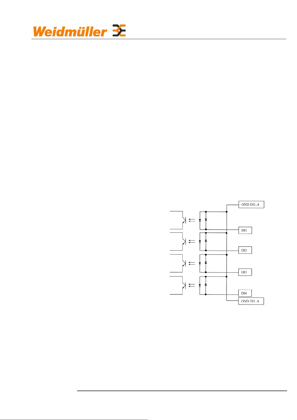
3.2.1 Digital inputs
Binary inputs for detection of external states as a high or low signal
• Electrically isolated and floating in two groups:
• Number: 8
• Input voltage: 0 … 30 VDC
• Input voltage status 0: 0 … 4 V / 0 … 1.2 mA
• Input voltage status 1: 10 … 30 V / 1.5 … 4.5 mA
• Debouncing can be parameterised
• Each input can be assigned event-related texts with system text
blocks.
Equivalent circuit diagram for the digital inputs:
Each input can be assigned event-related texts with system text blocks,
see Section 4.6 Alarm Message.
3-13
Page 16
Description of Functions
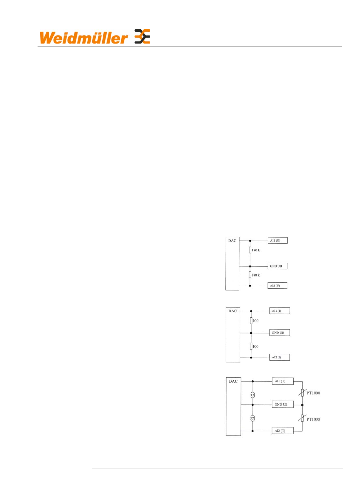
3.2.2 Analog inputs
Analog inputs for detection of external states as violation of minimum or
maximum limit values or as a percentage deviation; can be used to
measure voltage, temperature or current.
• Input ranges
▫ Voltage 0 … 10 V
▫ Current 0 … 20 mA
▫ Temperature PT1000
• Electrically isolated and floating in two groups:
• Number: 4
• Scaling and offset factors can be parameterised separately for each
measured value
• Debouncing can be parameterised
• Each input can be assigned event-related texts with system text
blocks.
Voltage sensor analog input
Current sensor analog input
Temperature sensor analog input
3-14
Page 17
Description of Functions
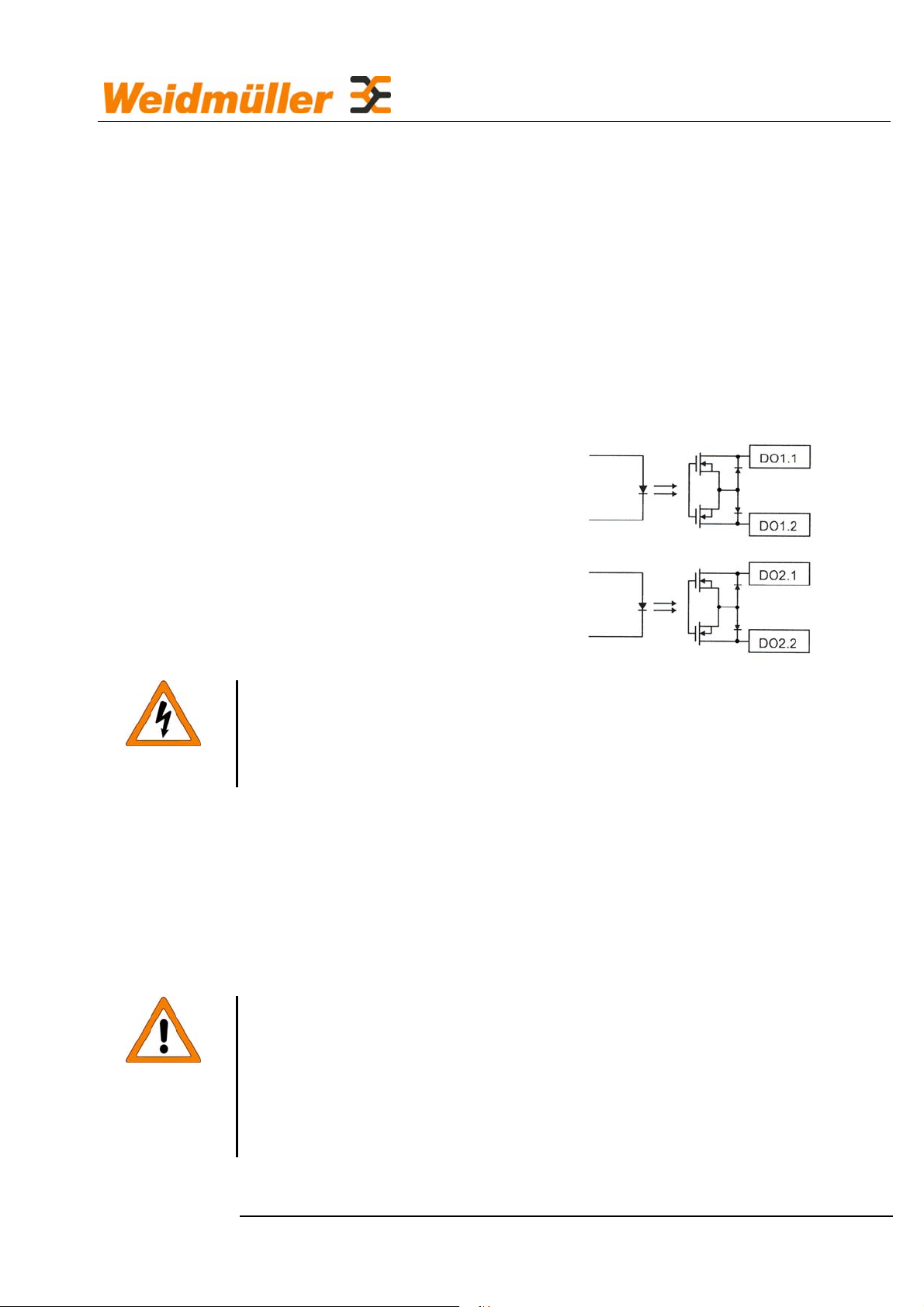
3.2.3 Digital outputs
The binary outputs can be used as follows:
• Signalling of successful/failed messages, see Section 4.6 Alarm
Message and 4.9 Function control.
• Remote-switching via telephone using tone dialling, see below
• Switching from another IE-GPRS-I/O of a group via X-Rec, see
Section 4.4 Digital inputs and outputs (Digital I/O) Digital outputs
• Operating voltage: 10 … 30 VDC
Output current: max. 400 mA
• Number: 4
Danger
Danger
The short-circuit and overload protection of the outputs must be
provided by external measures.
Remote-switching:
• Call the IE-GPRS-I/O using a telephone or mobile telephone.
• Enter the PIN (see Section 4.3 Access to the device).
• Press a number for the number of the output: 1 … 4
• Switching command, key 0 = OFF or 1 = ON.
When remote-switching, be especially cautious and work with
special care, as you cannot observe the reaction of the connected
plant from a distance. You should only switch an output if you are
fully informed as to all effects resulting for the plant. Make
absolutely sure that the health and safety of persons is not
endangered.
3-15
Page 18
NOTE
Description of Functions
3.2.4 Serial interface
The serial interface serves for communication with the monitored plant
or for communication of the plant with the connected devices via the
IE-GPRS-I/O.
The parameterisation and any firmware updating for the IE-GPRS-I/O
are performed via the serial interface.
The communication via the serial interface requires a fully
connected 1 : 1 cable. Regarding the information required to
configure the serial interface, please refer to Section 4.11 COM.
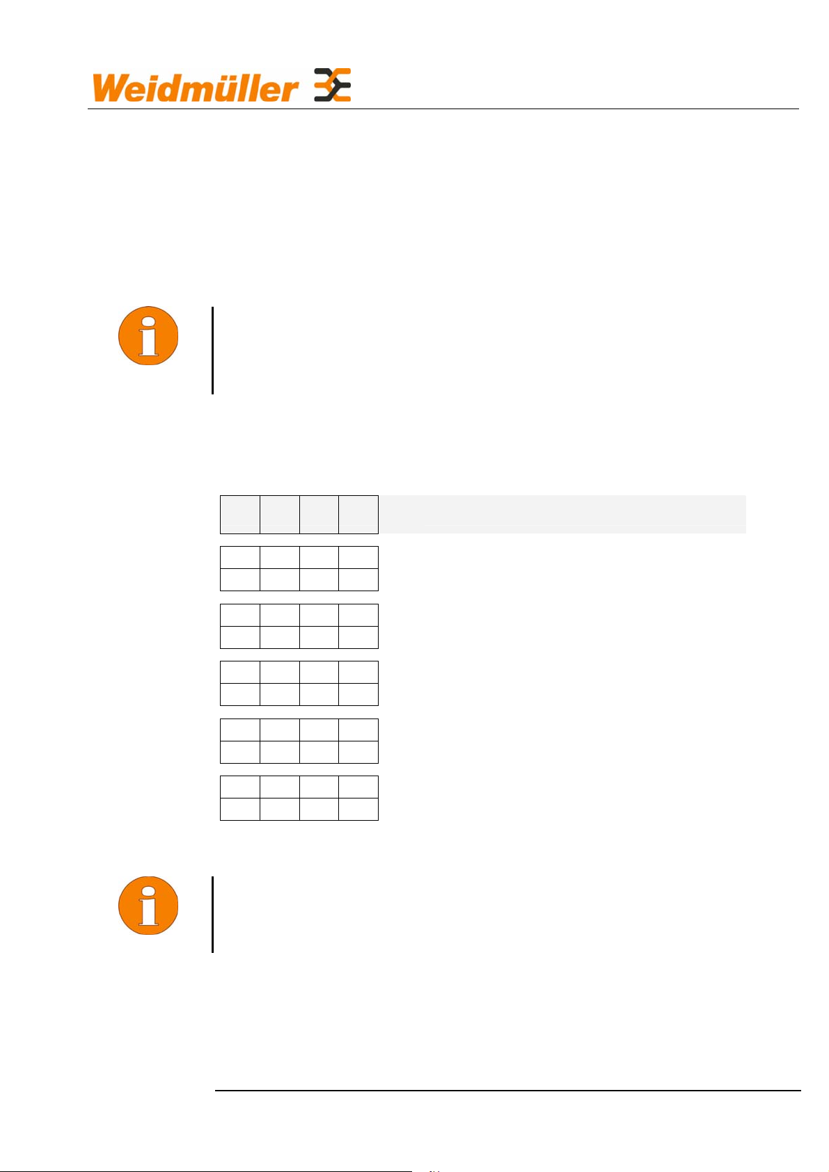
3.2.5 Operating modes of the serial interface
NOTE
1 2 3 4
OFF OFF OFF OFF
ON
OFF OFF OFF
ON
OFF OFF OFF
ON ON
OFF OFF
ON
OFF OFF OFF
Status
Flashin
Lights
DIP switches "Options" on the front panel
LED
OFF Operation as a signalling and GSM/GPRS system
Configuration locally; Connection from the serial
g red
interface to the PC via a modem cable (1 : 1)
Diagnosis at the serial interface using a terminal
green
program
All settings are reset to their defaults when the
operating voltage is connected.
Firmware update
To switch the operating mode, the IE-GPRS-I/O must be turned off;
after switching the DIP switch, it can be turned back on.
3-16
Page 19

Description of Functions
3.2.6 GSM modem
The GPRS module realises a virtual dedicated line. With an M2M
GPRS tariff of a mobile telephone provider, the only costs in addition to
a low fixed monthly charge are the costs for the actual data transfer. No
permanently installed fixed-network telephone connection is required.
Each IE-GPRS-I/O can be accessed online at any time in the same way
as a mobile telephone.
The data transfer is not provided via the exchange of telephone
numbers, but via an Internet-based protocol. The data are collected on
an exchange server and can be requested there at any time, without the
need to establish a direct connection to the IE-GPRS-I/O. The router of
the mobile telephone provider need not be configured.
Thanks to the use of non-public IP addresses of the provider, the
IE-GPRS-I/O is invisible to the Internet.
Additionally, software is supplied for an exchange server, which, for
example, can also be operated after a router.
CAUTION
3.2.7 SIM card
A SIM card is used to set the selected tariff and the possible
communication services for the IE-GPRS-I/O. The availability of the
services fax, e-mail and voice depends on the chosen tariff and on the
enabling of the SIM card used, see SIM card agreement.
Before you insert the SIM card, first turn off the device!
Inserting the SIM card
Use a pointed object to press gently into the hole beneath the SIM card
compartment and open the SIM card compartment. Insert the SIM card
into the card compartment such that the contact faces are visible.
3.2.8 GSM services
For the case that the virtual GPRS line is interrupted, alarms can be
issued additionally via the GSM network using the configurable services
SMS, e-mail, fax and voice messaging.
3-17
Page 20

Description of Functions
3.3 Settings of the operating system
CAUTION
3.3.1
(Firmware) update for the operating system
The operating system of the IE-GPRS-I/O is subject to continuous
further development to adapt it to the technical requirements and
customer wishes. Devices which are already in use may thus also
require a new operating system. The version of operating system
currently installed on your IE-GPRS-I/O can be displayed on the About
page of your web browser (see Section 4.16 About) or read out using a
terminal program (see Section 3.4.1).
When loading a new operating system, it may be necessary to reset all
settings to the factory defaults.
If the IE-GPRS-I/O is reset manually to its factory default settings
after installing the operating system, all settings already made are
lost; the user name and the password are also reset to the factory
defaults. Therefore, you should always document the current
settings before you make an update!
After the update, check both all settings and the access
protection.
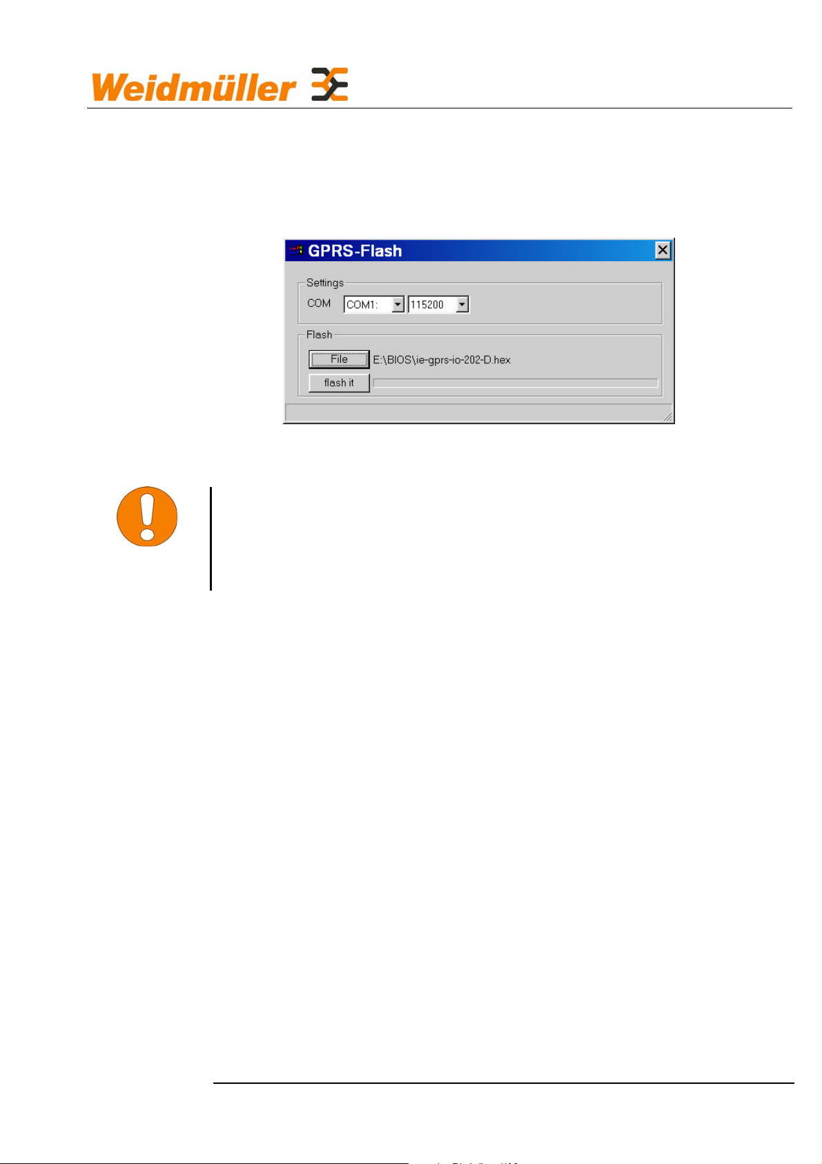
To load the operating system, use a loader.
Files required: gprs-flash.exe Loader
ie-gprs-io-xxxxx.hex Loader file
xxxxx stands for the version number
It is not necessary that both files are in the same directory.
• Connect the RS232 of your IE-GPRS-I/O to COM1 or COM2 of
your PC.
• Turn off the IE-GPRS-I/O.
• Set the DIP switch to 0-0-0-1.
• Turn on the IE-GPRS-I/O.
• Start gprs-flash.exe.
• Set the COMx interface and select the baud rate 115200.
• Select the loader file.
• Type flash it to start.
3-18
Page 21
Description of Functions
• The loading process will take approx. 5 min.
• Once loading is completed successfully, OK is displayed in the
status line.
NOTE
If the Loader does not permit any choice in the COM window, the
interfaces may already be occupied either by a driver of installed
software or by an application which is currently running.
The version number can also be displayed via the serial interface using
a terminal program. You need not enter a user name or the password to
display the version number. For communication via the serial interface,
see 3.4.1.
3-19
Page 22

Description of Functions
3.3.2 Resetting to the factory defaults
If you wish to reset the IE-GPRS-I/O to a defined initial state, you can
load the factory settings:
• Turn off the IE-GPRS-I/O.
• Set the DIP switch to 1-1-0-0.
• Turn on the IE-GPRS-I/O.
• The LEDs 1 … 4 will flash yellow for 5 s.
• The LEDs 1 … 4 will go out one after the other.
• The status LED flashes red.
• The factory settings are now loaded.
• Turn off the IE-GPRS-I/O.
• Set the DIP switch to 1-0-0-0.
NOTE
• Turn on the IE-GPRS-I/O; reparameterise the IE-GPRS-I/O if
necessary.
• Turn off the IE-GPRS-I/O.
• Set the DIP switch to 0-0-0-0.
• Turn on the IE-GPRS-I/O; the IE-GPRS-I/O is now ready for
operation.
Resetting the IE-GPRS-I/O to its factory settings will also reset the
password and the IP address!
Default factory settings
Default IP address: 192.168.1.120
User name: admin
Default password: 12345
3-20
Page 23

NOTE
Description of Functions
3.4 Communication between PC and
IE-GPRS-I/O
The communication is realised via a serial connection. To display
the HTML user interface of the IE-GPRS-I/O, Microsoft Internet
Explorer, version 5.5 or higher is required. For the relevant
information required to configure the IE-GPRS-I/O via the serial
interface, please refer to Section 4.1.
To configure the IE-GPRS-I/O using the HTML user interface, it is
imperative to know the current Ethernet address of your IE-GPRS-I/O.
The factory setting is 192.168.1.120.
• In the Windows operating system, set up the IE-GPRS-I/O as a
long-distance data transmission connection ("Dial-Up Networking",
see Section 4.1.1 Setting up the virtual modem and the longdistance data transmission connection under Windows XP).
• Configure a serial COM interface of your PC for the IE-GPRS-I/O
(see Section 4.1 Configuring the 218HIE-GPRS-I/O via the RS 232
interface).
• Establish the connection either by clicking on the previously created
shortcut on the desktop or use Start – Settings - Dial-Up
Networking - IE-GPRS-I/O ;
IE-GPRS-I/O stands for the name of the connection.
• In the Internet explorer, call the start page
http://
• After a few seconds, the start page of the parameterisation user
192.168.1.120/index.htm.
interface is displayed.
IE-GPRS-I/O is addressed directly via the long-distance data
The
transmission connection and cannot itself communicate with a network
connected to the PC. The IP address of the
IE-GPRS-I/O is not visible
in the network of the PC. Thus, no attacks are possible against the
IE-GPRS-I/O from the network. Furthermore, no address conflicts result
with devices with the same network address in the network.
3-21
Page 24
ATTENTION
Description of Functions
3.4.1 Diagnosis using a terminal program
If Windows HyperTerminal is used, previous activities, which may
also have arisen from other communication instances, are
displayed outside the visible window but can be viewed in the fullscreen mode. You should therefore set the view in the Terminal
window in the View menu to Fit to Window Size.
• Set and configure the serial interface to be used for the terminal
program:
• Disconnect the operating voltage.
• Set the DIP switch on the IE-GPRS-I/O to 0-1-0-0.
• Either select an existing connection from the saved connections or
create a new connection and select it.
• The terminal window remains empty.
• Once the connection has been established successfully, the
message Connected is displayed at the lower margin.
• Connect the supply voltage.
• The status LED lights red; the diagnostic data are transmitted to the
terminal.
• Once the status LED lights green, the data transfer is completed,
and the diagnostic data are visible in the terminal window.
• To reinitiate the data transfer, disconnect and then reconnect the
supply voltage.
3-22
Page 25

Diagnosis is also possible in the messaging mode.
Messages:
Description of Functions
Reset Hardware The IE-GPRS-I/O has been restarted.
Mon, 16 Jan … Date, time and time zone of the IE-GPRS-I/O
DI1 … 8 S Normally open contact
1s Debouncing set; the signal must have been
present for 1 s.
AI1 … 4 V Analog input set to
voltage measurement
1s Debouncing set; the signal must have
exceeded or fallen below the level for 1 s.
Network login Shows that you are logged into the network and
displays the receive signal level.
3-23
Page 26

Description of Functions
3.4.2 Remote servicing
It is possible to make all settings for the IE-GPRS-I/O from a remote
PC. To do so, you will need an analog modem.
The connection to the IE-GPRS-I/O is again established via "Dial-Up
Networking".
In "Properties" of "Dial-Up Networking", set the analog modem as the
transfer device.
Enter the number of your IE-GPRS-I/O as the dialling number; the
dialling number is indicated in your SIM-card agreement.
After establishing the connection, you can configure your IE-GPRS-I/O
as described in Section 4 Configuring the .
Reloading of the operating system is not possible via teleservice!
NOTE
NOTE
If no communication to the IE-GPRS-I/O can be established within
5 min., the connection is cancelled. The connection is also
cancelled, if no data have been transferred for 5 min. when the
connection is active. Subsequently, the IE-GPRS-I/O must be
reselected. Thus, unnecessary connection costs are avoided, as
would otherwise result if the connection was not cancelled
manually.
3-24
Page 27

Description of Functions
3.4.3 The "Passive" mode
The "Passive" mode provides a data connection from a remote PC, via
a modem and the IE-GPRS-I/O to a device connected to the serial
interface of your IE-GPRS-I/O.
Procedure
• The PC calls the IE-GPRS-I/O via a modem.
• The IE-GPRS-I/O accepts the call and establishes a connection.
• On the basis of the first data sent by the PC, the IE-GPRS-I/O
decides whether the data are part of a remote configuration for the
IE-GPRS-I/O or whether the data are intended for a downstream
device.
• If the data are intended for a downstream device, they are passed
to the serial interface. All data sent by the downstream device to
the serial interface are sent without changes to the remote
computer via the modem connection.
3.4.4 The "Transparent" mode
In the "Transparent" mode, it is possible for the internal GSM/GPRS
modem to be controlled by a downstream device.
• In this case, the establishing, cancellation and monitoring of the
connection must be controlled by the downstream device.
3-25
Page 28
Configuration
4 Configuring the IE-GPRS-IO
To start up your IE-GPRS-I/O, it must be configured first. The individual
steps for starting up will be explained in the present chapter.
4.1 Configuring the IE-GPRS-I/O via the RS 232
interface
The IE-GPRS-I/O is connected to a PC via the RS 232 interface
"RS232" using a modem cable. The RS232 protocol is used directly.
The IE-GPRS-I/O is addressed using Internet Explorer 5.5 or higher.
In the MS Windows operating system, install your IE-GPRS-I/O as a
modem for a long-distance data transmission connection.
4.1.1 Setting up the virtual modem and the long-
distance data transmission connection under
Windows XP/2000
If the modem and the long-distance data transmission connection are
already set up, proceed as described in Section 4.1.2.
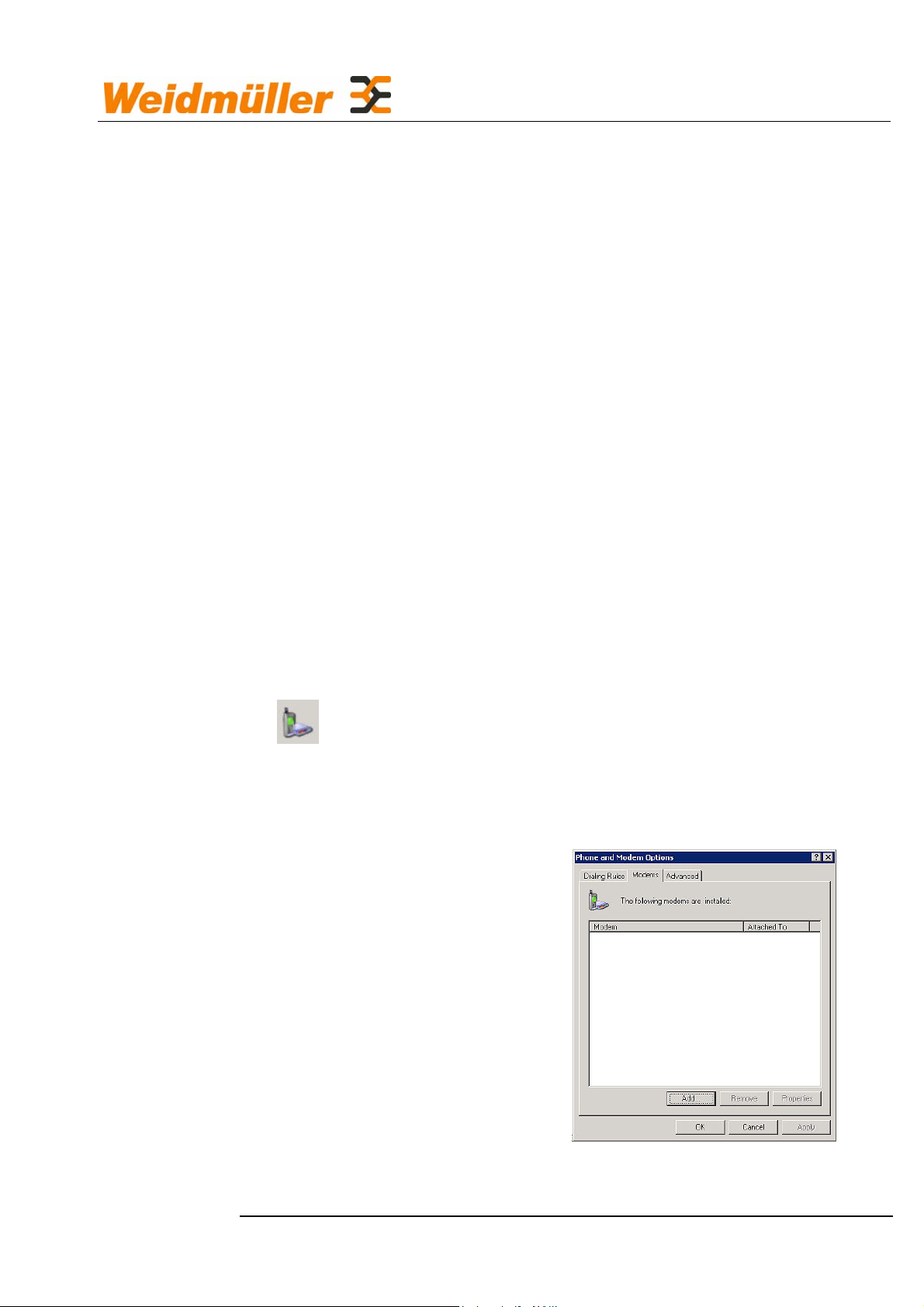
• Installing a new modem:
Select Start – Settings – Control Panel - Phone and
Modem Options and there
• "Modems – Add" tab.
4-26
Page 29
Configuration
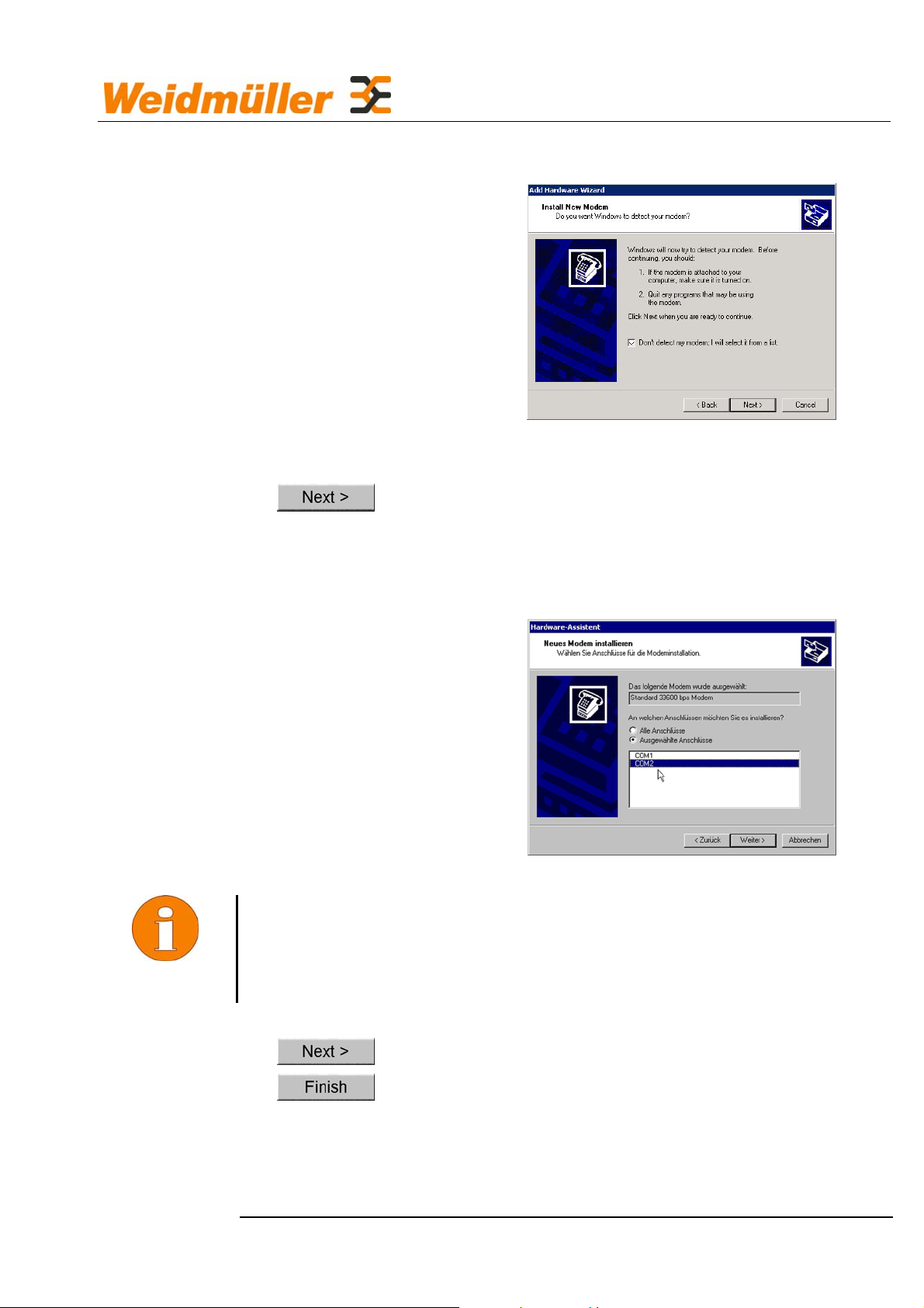
• The wizard assisting you in setting up a new modem is started:
• ; Select Don't detect my modem. select: I will select
it from a list.
•
• Select your modem from the following window:
(default modem type) -> default modem 33,600bps
NOTE
• Select the interface on your PC to which your IE-GPRS-I/O is
connected: COM1 or COM2
If an interface on your PC is not displayed, but is known to exist, it
is probably currently occupied by another interface driver, e.g. a
CAPI driver.
•
•
The installation of your modem is thus completed.
In the next step, the modem properties are set.
4-27
Page 30

Configuration
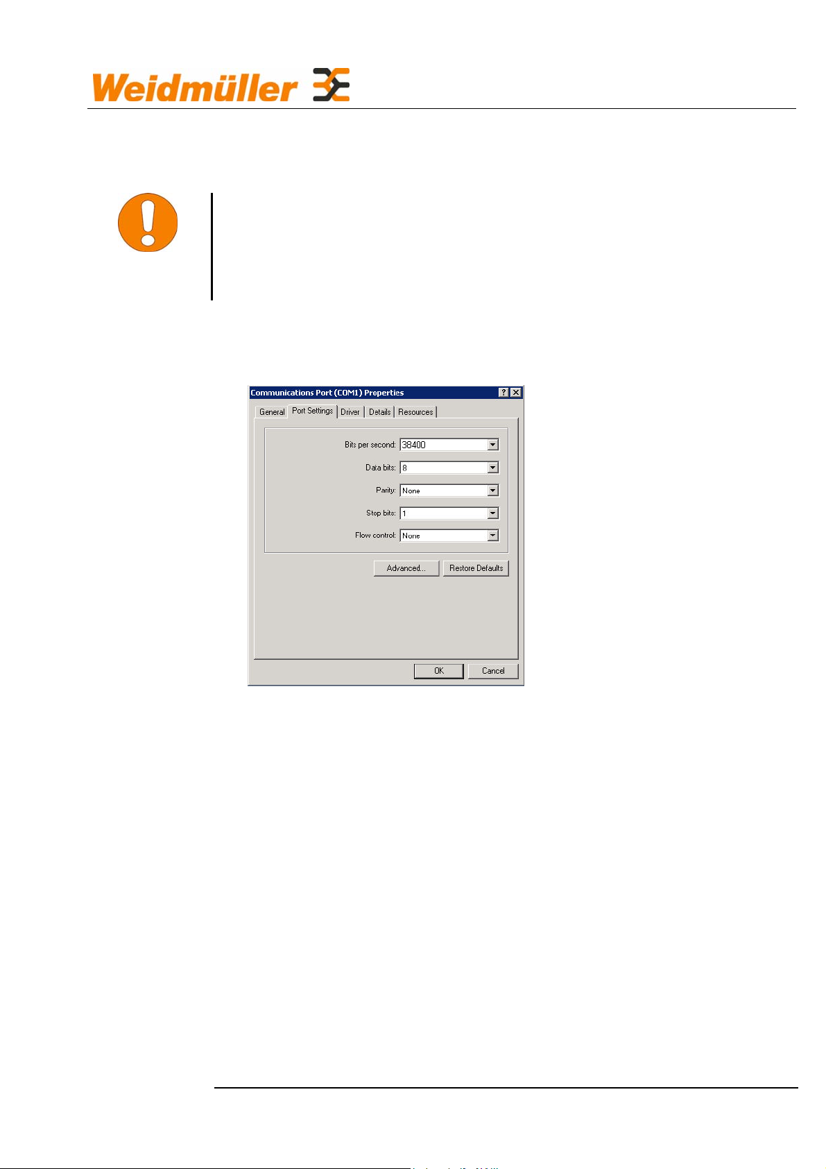
• Select Start – Settings – Control Panel - Phone and
Modem Options and there select
• the new modem:
• - "General" tab
• Make sure that Use this device (enable) is selected:
• "Modem" tab: Select 38400 as the maximum transfer rate.
• "Diagnostics" tab: Nothing need be entered here.
• "Advanced" tab: Nothing need be entered here.
• "Driver" tab: Do not make any changes here.
•
4-28
Page 31

Configuration
4.1.2 Installing the long-distance data transmission
connection
• Select Start - Settings – Control Panel – New
Connection Wizard;
• The wizard assisting you in establishing a new connection is
started.
•
• Select : Connection to the Internet
•
• Select : Connect using dial-up modem
•
• Select the modem you have just installed:
4-29
Page 32

Configuration
•
• Assign the long-distance data transmission connection a name:
• Enter any number:
• ; Add a shortcut to this connection on my desktop
•
4-30
Page 33

NOTE
After setting up is completed, the connection to the IE-GPRS-I/O
can be called directly by clicking on the shortcut on the desktop.
To do so, the Internet Explorer need not be reconfigured.
If no shortcut was created on the desktop, the connection can also be
called directly under Start – Settings – Network
Connections - IE-GPRS-I/O . "IE-GPRS-I/O" stands for the
name selected for the connection.
• Call the connection to the IE-GPRS-I/O:
Configuration
• Factory setting:
▫ User name:
admin
▫ Password: 12345
• ; Save this user name and password fort he
following users:
• ~ Me only
•
4-31
Page 34

Configuration
• "General" tab: Make sure that only the previously installed
modem is selected.
•
Modem configuration:
• Maximum speed (bps) 38400
• ; Enable hardware flow control
• ; Enable modem error control
• ; Enable modem compression
• ; Enable modem speaker
•
4-32
Page 35

Configuration
• "Dialling Rules" tab:
• ~ My Location - The once selected location is displayed.
•
• "Options" tab:
• ; Display progress while connecting
• ; Prompt for name and password, certificate, etc.
• Redial attempts: 3
• Time between redial attempts: 1 minute
• Idle before hanging up: 20 minutes
4-33
Page 36

• "Security" tab:
Configuration
• ~ Security options Typical
Allow unsecured password
• No further checkboxes must be set.
• "Network" tab:
• Type of dial-up server I am calling:
PPP Windows 95/98/NT4/2000 Internet
4-34
Page 37

Configuration
•
• ; Enable LCP extensions
• Enable software compression must not be selected.
•
• ; Internet Protocol (TCP/IP) Properties
•
•
4-35
Page 38

• ; Use default gateway on remote network
• PPP link:
Use IP header compression must not be selected.
• "DNS" tab
Configuration
• ~ Append primary and connection specific DNS
suffixes
;Append parend suffixes of the primäry DNS
suffix
• ; Register this connection's addresses in DNS
• "WINS" tab
4-36
Page 39

• ~ Disable NetBIOS over TCP/IP must be set.
• …
Back to "Properties of IE-GPRS-I/O"
• Advanced – Settings tab
Configuration
• | "On" must not be set!
• … - until all windows are closed.
4-37
Page 40

Configuration
4.2 Making the settings
The configuring tool required is Internet Explorer 5.5 or higher.
Starting configuring
• Disconnect the operating voltage.
• Set the DIP switch Options on the IE-GPRS-I/O for the
configuring mode to 1-0-0-0 (ON-OFF-OFF-OFF).
• Connect the serial interconnecting cable (1 : 1).
• Reconnect the operating voltage and wait until the Power LED
lights green and the Status LED flashes red.
• Open the long-distance data transmission connection either by
double-clicking on the shortcut IE-GPRS-I/O you have created on
the desktop or use Start – Settings - Dial-Up
Networking - IE-GPRS-I/O to establish the connection.
IE-GPRS-I/O stands for the name of the connection.
• Enter the default user name admin - if not stored.
• Enter the default password 12345 - if not stored.
• Start the long-distance data transmission connection.
• In your browser, type http://192.168.1.120/index.htm.
If you have not changed the default settings, the integrated web server
of your IE-GPRS-I/O will be started. The browser will create a dynamic
web site from the configuration data of your IE-GPRS-I/O.
It will take a few seconds until the page is displayed.
4-38
Page 41

ATTENTION
Once the page is open, you can save the address of your
IE-GPRS-I/O as a favourite (bookmark) in the Internet Explorer.
Configuration
The appearance and contents of the windows depend on the firmware
version installed. The appearance may deviate from the illustration
shown here. Furthermore, the screen display is influenced by the
browser and its settings. No language selection is possible in the
present version.
Function keys in the menus:
Save settings
Before switching to another menu, it is imperative to
wait until Finished is displayed in the status line of
the browser.
Accept saved settings immediately
Is only important if you make settings via a modem
connection. Only settings that have been saved are
accepted.
Back to higher-level menu
Restores the factory settings for the menu
concerned.
After a reset, the page must be refreshed with so
that the changes become visible.
4-39
Page 42

4.2.1 General Settings
The general settings apply for the device as a whole.
Configuration
Station number
• Dialling number used to call the station; is supplied with your SIM
card when the contract is concluded with the mobile telephone
provider.
• A number must always be entered.
• If you are uncertain, "1" can be left for the time being, and you can
change the number later (also remotely).
• This number is transmitted where appropriate, e.g. in the fax
identification.
• Max. 30 characters
Station ID
• An identifier that identifies the station in question unambiguously.
• With some messaging services (fax, e-mail, voice), the identifier is
included in the message.
• Letters and digits can be entered, but only the digits are announced
in the voice message, i.e. if "abc12de345" is entered, for example,
"12345" is announced.
• This field must not be left empty; if no identifier is needed, either
leave or re-enter 0000.
• Max. 16 characters.
4-40
Page 43

Configuration
Quit Pin
• 4-digit sequence of digits which is used to acknowledge SMS and
voice messages.
Acknowledgement must be enabled in the menu Messages with a
þ , i.e. acknowledgement of the messages is imperative (see
Section
• Only digits may be used.
• If 0000 is entered, you can use any numeric key of your telephone;
4.6).
in this case, only one key must be pressed.
• Always 4 digits.
SIM PIN
• 4-digit number which is supplied with your SIM card
• It is imperative to configure the SIM PIN if the SIM card requires a
PIN.
• If you have set your SIM card such that no PIN is required, 0000
must be entered to allow the device to log into the GSM network
without SIM PIN.
• Make sure that you enter the correct SIM PIN; an incorrect PIN,
however, will not usually block your SIM card (max. 2 attempts are
accepted to enter the PIN); but this cannot be guaranteed.
• If your SIM PIN is not properly configured, no message can be
triggered and thus no remote access to the device is possible.
• Older 5V SIM cards cannot be used.
• Always 4 digits.
Redialling
• Number of further attempts made by the device when a message is
to be sent if a target number cannot be reached or an error has
occurred.
• 1 automatic redial means max. 2 attempts.
• If a message is sent as an SMS with receipt acknowledgement, the
number of automatic redials applies first for the SMS and then once
more for the acknowledgement.
• The next recipient in the messaging chain is only processed after
the maximum number of automatic redials is reached.
• Automatic redialling may also occur if the message has reached the
recipient, but, for example, an error has occurred in the final phase
of the message.
• 0 ... 9
4-41
Page 44

CAUTION
Configuration
Text Header
• Here you can enter a text that can be inserted in the message texts
using the text block #HEAD#.
• For example, the name of the plant or the name of the company
can be entered, or a description of the states of the digital I/Os.
• Max. 80 characters.
• For further fixed text blocks, see Section 4.6 Safety Notes.
4.3 Access to the device
4.3.1 Device Access
These settings control the access to the device.
When making these settings, proceed very carefully; otherwise,
access to the device may no longer be possible without undue
difficulties. This would pertain both to local and remote access.
4-42
Page 45

Configuration
User name for PPP
• User name used to connect via "Dial-Up Networking, whether
remotely or locally; see "Configuring the long-distance data
transmission connection", Section 4.1.1.
• Max. 30 characters
Password for PPP choice
• User name used to connect via "Dial-Up Networking", whether
remotely or locally, if the device is to be accessed via voice.
• Max. 30 characters
Password repetition
• Repetition of your password to verify the password for PPP dialling
4-43
Page 46

ATTENTION
Configuration
Certified dialling numbers
• Dialling numbers of fixed/mobile telephones and modems from
which a remote access is to be granted to the device.
• 8 access numbers are possible.
• If no numbers are entered, access is possible from any dialling
number.
• The dialling number must have the format +49123456789; no
blanks or special characters are allowed.
If one or several numbers are entered here, access to the device
can only be realised from one of these numbers. It should always
be tested whether your dialling number is transmitted. If the
dialling number is suppressed by the telephone or by the provider,
no remote access to the IE-GPRS-I/O is possible from this device.
NO remote access to the device will be possible in case of
incorrect settings or incorrect entries for the numbers.
Call accept
~ Data mode
• If you use a SIM card that does not possess a data number, it is
nevertheless possible to accept the call in the data mode if this
feature is set.
• Call acceptance in the "Data" mode, however, requires that the
data mode is enabled for incoming calls for your SIM card by the
mobile telephone provider.
~ Voice mode
• If the call is accepted in the "Voice" mode, it is possible to accept
the next call in the "Data" mode via telephone using the key 9
provided that you have dialled successfully in the "Voice" mode see temporary data mode for GSM devices.
4-44
Page 47

Configuration
4.4 Digital inputs and outputs (Digital I/O)
CAUTION
Active on
• High: A message can be triggered if a voltage in the range
12 ... 24 V is present at the input.
• Low: A message can be triggered if a voltage of 0 V is present at
the input.
• Level change: A message can be triggered if the input voltage
changes from 0 V to 12 ... 24 V or vice versa.
The input voltage must NOT lie within the range of 4 … 10 V. In this
voltage range, no reliable status detection is provided.
4-45
Page 48

Configuration
Debouncing time
• The relevant input signal must have been present without
interruption for at least the set debouncing time for a message to be
triggered; shorter disturbances cannot trigger a message.
Text for High
• A text that can be inserted into the message block using the text
block #VAL# or #DI1#...; thus, it is possible to modify the message
text dynamically, depending on the particular event.
• Max. 16 characters.
Text for Low
• A text that can be inserted into the message block using the text
block #VAL# or #DI1#...; thus, it is possible to modify the message
text dynamically, depending on the particular event.
• Max. 16 characters.
Report
NOTE
If you wish a message to be triggered via an input, it is imperative
that the appropriate input be set by ; .
Digital outputs
Switching time
• The digital outputs can be switched by events (see Section 4.6
Alarm Message) "Switch if" and Section 4.9 Function control
"Switch if".
• Switching time in seconds for which the output remains closed after
an event has occurred and before it reopens automatically
4-46
Page 49

ATTENTION
ATTENTION
The switching time is not effective when switching the digital
outputs remotely via telephone.
X-Rec
• Remote-switching by a digital input of another IE-GPRS-I/O in a
group of IE-GPRS-I/Os
• Two IE-GPRS-I/Os are included in a group.
; Connects the IE-GPRS-I/O as the receiving device of the group
to the digital input of the sending IE-GPRS-I/O.
• In all cases, inputs and the outputs with the same number are
connected; linking is only possible for the digital inputs 1 … 4.
Digital outputs that are connected to another IE-GPRS-I/O via
X-Rec must not be used for issuing messages (see Section 4.6
Alarm Message, "Switch if" and Section 4.9 Function control
"Switch if".
Configuration
4.5 Analog inputs ("Analog I")
4-47
Page 50

Configuration
Measured unit
• Selection of the analog measurement unit: Volt
Ampere
Temperature
Measured value
• This field displays the measured value of the inputs.
• Clicking on the field refreshes the measured values of the two
analog inputs.
Factor
• It is possible to scale the measured value with a factor.
In this case, the calculation is performed as follows: (Factor ∗
measured value) + offset, i.e. the slope of the measurement
characteristic is not changed so that the displayed measured value
can be matched to the physical measurement quantity.
Example: Assumed 0 … 10 V is to correspond to a water level of
0 … 100 cm, the factor to be set is 10.
Offset
• It is possible to shift the measured value using an offset.
In this case, the calculation is performed as follows: (Factor ∗
measured value) + offset, i.e. the zero of the measurement
characteristic is offset.
Debouncing time
• The measured value must have been either higher or lower than
the appropriate limit value for at least the set debouncing time for a
message to be triggered.
Display unit
• A unit, e.g. "V", which is inserted into the text block #AI1#, #AI2#,
together with the measured value.
• Max. 3 characters.
Upper limit value
• If the measured value exceeds the upper limit value, a message
can be triggered.
• Further messages can only be triggered if the measured value has
fallen below the lower limit value and has then again risen above
the upper limit value.
Text for upper limit value
• A text that can be inserted into the message text using the text
block #VAL#; thus, it is possible to modify the message text
4-48
Page 51

Configuration
• dynamically, depending on the particular event;
max. 16 characters.
Report
• If this field is checked, a message is triggered when the upper limit
value is exceeded.
Lower limit value
• If the measured value is lower than the lower limit value, a
message can be triggered.
• Further messages can only be triggered if the measured value has
risen above the upper limit value and has then again fallen below
the lower limit value.
Text for lower limit value
• A text that can be inserted into the message text using the text
block #VAL#; thus, it is possible to modify the message text
dynamically, depending on the particular event;
• Max. 16 characters.
Report
• If this field is checked, a message is triggered when the measured
value falls below the lower limit value.
Signalling when the measured value is lower/greater than a limit
value
• If the measured value falls below the lower limit value or exceeds
the upper limit value, a message is triggered.
• Further messages can only be triggered after the measured value
has fallen below or exceeded the corresponding other limit value.
Change
Signals when a measured value changes.
• A message can be triggered if a measured value changes by a
certain amount.
• The appropriate change is specified as a percentage and refers to
the measuring range of the input, e.g. voltage 0 ... 10 V; 10 %
corresponds to a change of 1 V.
NOTE
If a measured value is monitored for changes, the debouncing time
is not considered, meaning that a message is triggered
immediately if the measured value changes accordingly.
4-49
Page 52

4.6 Alarm Message
Configuration
Input
• The following events can be selected to trigger a message:
REPORT An error has occurred, e.g. faulty
login into the GPRS network
DI1 ... DI4 Digital inputs 1 to 8
AI1 … AI2 Analog inputs 1 and 4
EI1 … EI16 Signal inputs, serial, via the TUP protocol
Text
• Enter the text you wish to be displayed in the message in the text
field, for example "Fault: Pump".
• The maximum length permitted, including all text blocks, is 160
characters.
• Longer texts will be truncated.
• The following text blocks can be used to create a message text
dynamically:
▫ #HEAD# Inserts the header (menu option "General").
▫ #DATE# Inserts the sending date of the message.
▫ #TIME# Inserts the sending time of the message.
4-50
Page 53

Configuration
▫ #VAL# Inserts the text for the input belonging to the message,
depending on its value at the time when the message was
triggered.
▫ #DI1# ... DI8# Inserts the text for the digital input belonging to the
message, depending on its value at the time when the message
was triggered.
▫ #AI1# ... AI4# Inserts the measured value and its unit for the
analog input, depending on its value at the time when the
message was triggered.
▫ #ATIME# Time when the message is triggered
▫ #ADATE# Date when the message is triggered
Message Target
• To configure the appropriate message sequence:
▫ 8 message targets can be defined per input.
▫ The message targets are contacted one after the other until a
message has been sent successfully;
this makes sense, for example, with graduated standby services.
NOTE
• Enter the appropriate target mobile telephone number for short
messages (SMS).
• Enter the appropriate target e-mail address for e-mails, etc.
Service
• Select the appropriate transmission method,
e.g. D1 SMS = Send SMS via the D1 network / E-mail = Send e-
mail to the specified address, etc. ...
The messaging service must correspond to the target! For
example, you cannot sent an SMS to an e-mail address.
; ACKN
• If acknowledgement is possible for this messaging service (menu
option "Messaging services"), this feature can be activated here.
; ALW
• Message targets that are always to be informed irrespective of the
message sequence.
4-51
Page 54

Configuration
▫ The message targets form a message sequence.
The message sequence is interrupted if a target of this sequence
was informed successfully, including acknowledgement.
▫ If a message target is to be informed in any case, irrespective of
its position in the message sequence, the message targets must
be marked additionally with "ALW".
- Example: Shift schedule in a sequence of 3 and additionally a
fax to the exchange centre, which is always to be sent. -
▫ Message targets that are marked with an "I" have no influence on
the message sequence, i.e. even if such a message target was
informed successfully, the message sequence is not quit.
Weekday
• The relevant message is only sent on the marked days of the week;
thus, a simple shift schedule can be realised.
from - to
• The message is sent during the time "from - to".
NOTE
• If the time period passes midnight, the message is still sent even if
the second day of the week is not marked,
for example, from = 07:00 p.m. to = 08:00 a.m. Mon
Tue is marked.
If the input is now triggered on Wednesday at 07:50 a.m., the
message is sent even though Wed is not marked.
Switch if
• Here you can specify that one of the digital outputs can be
switched:
▫ If no message target was informed successfully.
▫ If one message target was informed successfully.
▫ If all message targets were informed successfully.
▫ Message targets marked with "ALW" are ignored.
Save your settings before switching to a different input!
4-52
Page 55

4.7 Message Services
Configuration
List box "Messaging services"
▫ D1 SMS
▫ D2 SMS (Vodafone)
▫ E+ SMS
▫ FAX
▫ E-mail
▫ VOICE
• Use the NEW button to create a new messaging service.
• An unambiguous name must be specified.
Name
• The name of the messaging service can be changed.
• Max. 8 characters (no letters with accents).
Protocol
• Transfer protocol
• Max. 8 characters
Text length
• Maximum length of the message text
• Max. 160 characters; for pagers only 80 characters permitted.
• If the field is empty, no check is performed to determine whether a
message text has actually been configured (e.g. for voice
messages).
• 1 ... 160
4-53
Page 56

Configuration
Country code
• A prefix placed in front of the actual target number of the recipient
for this messaging service.
• Leading zeros in the number of the recipient are omitted,
for example, country code = 0049 target number = 0171 1234567;
in this case, the message is sent to 0049171 1234567.
• It is recommended to use the syntax 0049, 0041... .
• The country prefix can also be entered directly in the target number
of the recipient (menu option "Messages").
• Max. 8 characters
Country code SMSC
• A prefix placed in front of the actual SMSC dialling number for this
messaging service.
• Leading zeros in the number of the recipient are omitted,
for example, country prefix SMSC = 0049 SMSC dialling number =
01770610000; in this case, the short message is sent to 0049
01770610000.
• It is recommended to use the syntax +49, +41... .
• Max. 8 characters
Phone number SMSC
• Various messaging services require that an SMSC (Short Message
Service Centre) is involved; this centre is used, for example, to
send the SMS.
• This dialling number is provider-dependent.
• An incorrect SMSC may be the cause for an SMS not reaching the
recipient.
• Max. 30 characters
Init String
• Additional information which can be transmitted in addition to the
relevant messaging protocol.
• Max. 30 characters
Receipt if possible
• With various messaging services, an additional acknowledgement
call is possible, with others not (e.g. fax, e-mail).
• yes/no
4-54
Page 57

NOTE
Configuration
The messaging service "E-mail" requires an e-mail account, see
Section 4.9.
If you select E-mail, a link is displayed to another menu option where
you can make further settings required for this messaging service.
Further settings
ISP
• For selecting an Internet service provider which has been set up
under IPS settings, see Section
4.8.
Host name
• A name that identifies the device; can be selected freely.
Sender's e-mail address
• The e-mail address that belongs to the e-mail account (access) of
the IPS, see above.
4-55
Page 58

Configuration
SMTP server/IP
• Server via which the e-mail is to be sent
• This server is bound to the e-mail account.
• Either a server name or an IP address can be specified; syntax:
aaa.bbb.ccc.ddd, for example 213.165.64.20
These data are provided by your e-mail provider.
• This server can be compared with the posting box used to send
conventional letters.
Authentication
• Most e-mail providers require an authentication to send e-mails via
an SMTP server.
• Selection:
▫ none
No authentication is required, or the authentication is provided
via the senders and often via the recipient's e-mail address (see
Section 4.6 Alarm Message).
In other words: Only e-mails with certain addresses can be sent.
▫ SMTP after POP
An authentication procedure which is supported by many e-mail
providers.
Before sending an e-mail, the user must access his e-mail inbox
(see below) using his password and his user name.
Subsequently, he is left a defined time window of, for example,
15 minutes, within which he may send e-mails via SMTP. Thus,
the successful POP authentication serves as an authentication
for sending via SMTP.
▫ SMTP AUTH
An authentication method which is supported by many e-mail
providers.
With a user name and password, a user is entitled, for example,
to send e-mails via the above-specified
SMTP server.
4-56
Page 59

Configuration
POP Server IP
• Inbox server of your e-mail account
• This server can be compared with the letter box for receiving
conventional letters.
User ID
• The user name or, for example, the customer number of your e-
mail account.
Password
• The password that is used for access to the inbox or for the SMTP
authentication.
Password confirmation
• A confirmation (input repetition) of your password to avoid incorrect
inputs.
4.8 ISP settings for the Internet access
The provider supported by the Weidmüller is Vodafone.
4-57
Page 60

Configuration
An e-mail is always sent via the Internet. To this end, an Internet
Service Provider must be configured through which access to the
Internet is possible from a mobile wireless device.
There are call-by-call providers allowing this access; furthermore, all
mobile service providers offer their own Internet access (see your
Mobile Service Agreement).
ISP1
Connection
• GPRS or GSM
• For functions that are permanently online, no GSM should be used
(excessive costs)
Provider
• Vodafone (the name for the provider can be selected freely)
• It should be visible whether GSM or GPRS is used.
• Max. 30 characters
Call number
• The number at which the provider is to be reached.
• Max. 50 characters.
Access Point
• Required for connection to the GPRS network.
• For Vodafone: www.vodafone.de
• Max. 50 characters.
Init
• Additional initialisation commands (AT commands)
• Could be necessary for GPRS, but is generally not required
(for Germany and Switzerland not necessary to date)
• Max. 50 characters.
User name
• The name with which the user is to be logged into the ISP.
• Max. 30 characters
Password
• The password which is to be used when logging into the ISP.
• Max. 30 characters
4-58
Page 61

Configuration
DNS1
• Optional DNS (Domain Name Server)
Syntax: e.g. 217.237.151.97
• Normally, no entry is necessary, since the settings are transferred
by the ISP.
• Even if a DNS is received by the ISP, it is not this entry which is
used, but that of the ISP.
DNS2
• Optional DNS (Domain Name Server)
Notification: e.g. 217.237.151.97
• Normally, no entry is necessary, since the settings are transferred
by the ISP.
• Even if a DNS is received by the ISP, it is not this entry which is
used, but that of the ISP.
• Two ISPs can be configured, e.g. one for GPRS and one for GSM.
Thus, if GRPS is not available, it is nevertheless possible to send
an e-mail as an error message.
ISP2
ISP2 is the backup connection for ISP1. Status messages via e-mail are
sent via IPS1 and GPRS by default. In case of failure of this connection,
an error message, e.g. via e-mail, is sent via the connection configured
under ISP2. Thus, alternative sending is possible via GSM.
4-59
Page 62

Configuration
4.9 Function control
The IE-GPRS-I/O can issue a cyclic message (sign of life) as a function
monitoring signal.
Text
• Enter the text you wish to be displayed in the message in the text
field, for example "
Fault: Pump1".
▫ The maximum length permitted, including all text blocks, is
160 characters.
Longer texts are truncated.
It is possible to use text blocks to create a message text
dynamically, see Section 4.6 Alarm Message.
Target
• Two targets can be specified.
▫ Enter the appropriate target mobile telephone number for short
messages (SMS).
▫ Enter the appropriate target e-mail address for e-mails, etc.
Sun - Sat
• Enter the day of the week, time 00:00 and interval 0 min here.
▫ The message is sent on the weekday set and at the time set.
▫ If an interval > 0 has been set, a message is issued at the
interval as specified in minutes.
This process ends at midnight of the set weekday.
4-60
Page 63

Configuration
• ; ACKN
If acknowledgement is possible for this messaging service (menu
option "Messaging services"), this feature can be activated here.
• ; ALW
▫ The message targets form a message sequence, in other words:
If a target of this sequence was informed successfully (including
acknowledgement), the message sequence is cancelled.
▫ If, however, a message target is to be informed in all cases, this
target can be marked under "ALW".
▫ Message targets that are marked with "I" have no influence on
the message sequence. In other words: Even if such a message
target was informed successfully, this does not end the message
sequence.
• Switch if … Message was successful
Here you can specify that one of the two digital outputs is to be
switched if:
▫ No message target was informed successfully.
One message target was informed successfully.
All message target were performed successfully.
▫ Message targets marked with an "I" are ignored.
4-61
Page 64

Configuration
4.10 Server
The Internet exchange server is operated with further partners on behalf
of Weidmüller. The server is a relational database which can be
accessed externally via SQL queries. The server itself need not be
configured externally by the customer. To be able to use the server,
only the following settings are required:
Interconnection between two or several IE-GPRS-I/Os to one another
can only be provided via the exchange server. The exchange server
performs the data transfer from one IE-GPRS-I/O to the other
IE-GPRS-I/O or within a group of several IE-GPRS-I/Os.
All IE-GPRS-I/Os log into the exchange server with a password, a code
and a group. Several IE-GPRS-I/Os of a group can communicate with
each other; the
communicate with each other.
IE-GPRS-I/Os may be master, slave or master/slave.
A master sends data to all slaves and master/slaves of a group, not to
other masters. The master receives data from all slaves and
master/slaves of a group, but not from other masters.
A slave sends data to all masters and master/slaves of a group, not to
other slaves. The master receives data from all masters and
master/slaves of a group, but not from other slaves.
IE-GPRS-I/Os of different groups, however, cannot
ISP
• Internet service provider via which the IE-GPRS-I/O establishes
connection to the exchange server
• GPRS should be set as the service used (see 4.8 ISP settings for
the Internet access).
4-62
Page 65

Configuration
Server
• Server name
▫ Can be resolved via DNS or
▫ Server IP address
• If both are entered, an attempt is made first to reach the server via
its server name.
ID
• Each IE-GPRS-I/O must contain an unambiguous name for
identification within a group.
Observe use of uppercase/lowercase letters!
Password
• Password for identification
Observe use of uppercase/lowercase letters!
Group
• Communication group to which the IE-GPRS-I/O is to belong.
Observe use of uppercase/lowercase letters!
4-63
Page 66

Configuration
Mode
• Master:
Master IE-GPRS-I/O talks -> all slaves listen
• Slave:
Slave IE-GPRS-I/O talks -> only the master listens
• Master/slave:
Listens to everybody
Connect automatically
• If Connect automatically is enabled, the IE-GPRS-I/O
attempts to establish the connection to the exchange server
automatically after a reset.
Send all input states
• Time interval at which the IE-GPRS-I/O sends its input status to the
exchange server
▫ 0 means that the input status is sent not cyclically.
4.11 COM port
Settings for the serial interface for the data traffic with connected
devices. The serial interface is only activated in the DIP switch position
1-0-0-0 in the "Configuring" mode; in the "Diagnostic" mode 0-1-00, it is set to 38,400 Baud as a fixed transfer rate.
See Section 3.4 Communication between PC and IE-GPRS-I/O.
4-64
Page 67

Configuration
4.12 Logbook
The IE-GPRS-I/O manages a logbook where important events,
messages etc. are entered.
Max. 255 entries are possible. If this number is exceeded, the oldest
entries are overwritten. The entries can be viewed and deleted under
the menu option "Logbook". Normally, the log file need not be reset.
The entries are displayed in the form "Weekday", "Date", "Time",
"Event" and "Error code".
4-65
Page 68

Configuration
4.13 Cost control
The IE-GPRS-I/O monitors the data volume for GPRS connections and
the online time for GSM connections.
To this end, you must enter the specifications from your mobile
subscriber agreement in the menu Cost control.
Rounding error
• Each time a connection is established to the GPRS network, the
provider debits a certain data volume from you at a flat rate. The
amount of this value depends on the appropriate mobile subscriber
agreement. It is recommended to use ALWAYS a tariff model with a
rounding error as low as possible.
Reset to
• Date on which the counters are reset to 00:00 o'clock
4-66
Page 69

Limit value
• Byte counter
The following limit values can be set for two graduated report
messages.
Example:
▫ If a volume tariff of 10 MB/month was agreed with the mobile
service provider, with byte counter1 = 5 MB, a report message is
issued when half of this volume has been used, and with byte
counter2 = 8 MB again at 80 %. The setting is made in the menu
"Messages", see Section
• Online time
Due to technical reasons, the counter can only provide a rough
overview (guide value) of the actually used volume.
Example:
▫ Necessary repetitions when sending data which cannot be
protocolled by the
IE-GPRS-I/O
4.6 Alarm Message.
Configuration
CAUTION
▫ Different protocol overheads when sending
Counter
• Current counts
The displayed values apply with reservation and serve only as
guide values to provide an overview.
No guarantee can be given for the correctness of the abovementioned counter values, as the invoicing procedures of the
individual providers may differ.
The invoices of the provider are binding.
4-67
Page 70

4.14 Troubleshooting
4.15 Systemtime
Configuration
When the IE-GPRS-I/O starts an Internet connection (e.g. for sending
an e-mail), it can match its system clock with a time server (SNTP
server) on the Internet.
Summer time
• Summer/winter time is observed when setting the clock.
4-68
Page 71

SNTP server
• IP address or host name of the time server
Default setting: Time server 1 of PTB in Braunschweig
• Time zone in which the IE-GPRS-I/O is located (Germany +1)
• If "Set clock" is set, the time match is performed when the Internet
connection is first established.
The internal clock is backed up for approx. 75 hours. If the
IE-GPRS-I/O remains without operating voltage for longer, the
clock must be reset via the time server.
Configuration
ATTENTION
4.16 About
Homepage of the manufacturer
Ver: Version number of the operating system
4-69
Page 72

5 Hardware
5.1 Installation
This chapter provides all relevant information on the dimensions.
5.1.1 Dimensions
The diagram below shows the dimensions of the IE-GPRS-I/O:
Hardware
Dimensions [mm]
Height 156 plus space for connectors and lines of the
inputs and outputs above and beneath the
device
Width 44
Depth 140 plus space for connectors and lines for the
power supply,
for the serial interface connector
and for the aerial/aerial connector
5-70
Page 73

NOTE
5.1.2 Installing the top-hat rail
The IE-GPRS-I/O can be fastened on a top-hat rail which complies with
the standard EN 50022:
1
35
7,5
This top-hat rail must be fastened on the control cubicle wall such that a
conductive connection is provided.
Observe the instructions of the manufacturer with reference to
fastening.
Hardware
NOTE
Installation
Pull the top-hat rail downwards, at the same time pushing the device
back onto the top-hat rail.
Removal
The top-hat rail adapter is offered in two variants, resulting in the
different direction of movement when unhooking from the top-hat
rail. Therefore, before unhooking, check whether the IE-GPRS-I/O
is to be moved upwards or downwards against the retaining
spring.
To remove the device, unhook it by pushing it firmly upwards or
downwards, and then remove it forwards from the top-hat rail.
5-71
Page 74

Hardware
5.1.3 Wall mounting
There are two mounting plates intended for mounting of the device on
the wall. The mounting plates are fastened with screws on the rear side
of the housing and must be mounted as shown in the illustration. The
top-hat rail adapter must be removed if you mount the device on the
wall.
Mounting using a top-hat rail Mounting on the wall
5-72
Page 75

When mounting a top-hat rail adapter on the rear of the housing, it
is imperative to observe the correct position of the retaining
spring:
Hardware
NOTE
Plastic variant: Retaining spring at the bottom
Aluminium variant: Retaining spring at the top
CAUTION: Incorrect mounting will reduce the retaining force of the
top-hat rail adapters.
Only use the original screws of the top-hat rail; longer screws will
damage the electronics of your IE-GPRS-I/O. The screws to be
used are M3 x 8 round head for adapters with plastic insert and M3
x 4 countersunk head for aluminium adapters.
5-73
Page 76

Hardware
5.2 Installation notes
Make sure that at least 35 mm of space is left above the module.
A space of 35 mm must be provided beneath the module for routing of
the cables for the interfaces and for the power supply.
5.2.1 Functional earthing
For functional earthing, connect the "Functional earthing" terminal on
the housing of the IE-GPRS-I/O to the equipotential bonding of the
control cabinet.
The connection "Functional earth" serves for purely operational
functions (modem function).
Make sure that the cross-section of the interconnecting line does not
exceed 4 mm2.
5-74
Page 77

Hardware
5.3 Installation guidelines
The specified maximum operating temperature pertains to the air
temperature beneath the IE-GPRS-I/O (air inlet).
Observe a sufficient distance to devices emitting strong electromagnetic
radiation (such as frequency converters, transformers, motor
controllers, etc.). The clearance between these devices and the
IE-GPRS-I/O should be as large as possible. If necessary install a
shielding of partition walls (MU metal).
Do not plug or remove the devices during operation!
Before removing a IE-GPRS-I/O, also remove the relevant plugs and
connectors.
Do not connect or remove the connectors if the supply lines are still live
(all-pole disconnection).
5.4 Storage and storage temperatures
The following values will apply for storing:
Storage temperature: -10 ... +70 °C
Humidity: 30 ... 95 % (not condensing)
5.5 Operating temperature, humidity
The following values will apply for operation:
Operating temperature with
vertical mounting position: -10 ... +55 °C
Humidity: 30 ... 95 % (not condensing)
5-75
Page 78

Hardware
5.6 Status display
Three LEDs are located on the front panel of the IE-GPRS-I/O to
display the operating status. To display the status of the port, 12 further
LEDs are installed on the upperside/underside of the device to display
the states of the digital inputs/outputs.
Status of the GPRS/GSM communication
Voltage level at the
digital inputs/outputs
Mode selector switch
Operating state of the IE-GPRS-I/O
Status of the operating voltage
5-76
Page 79

5.6.1 Display "POWER on/off"
LED Description
OFF The supply voltage is turned off.
Lights red
Lights green The supply voltage is turned on.
Insufficient power supply
IE-GPRS-I/O is not ready for operation.
The
5.6.2 "Status" display
LED Description
OFF -
Lights red During the phase of initialisation of the IE-GPRS-I/O
Lights green IE-GPRS-I/O in the standby mode
Flashes quickly
green
Flashes slowly
green
Flashes quickly
red
Flashes slowly
red
Flashes quickly
red
Connection to the exchange server established
Message is just being issued
Error while signalling (if DIP1 OFF)
In the "Programming" mode (DIP1 ON), but long-distance data
transmission connection not yet established
In the "Programming" mode (DIP1 ON) and long-distance data
transmission connection established
Hardware
5.6.3 "Line" display
"Line" LED Description
OFF offline
Lights green GSM module is ON
Flashes slowly
green
Flashes quickly
green
GSM module is logged into the GSM network
(SIM PIN OK)
Call detected, call accepted
5-77
Page 80

5.6.4 "Ports" display
LED 1 … 4 Digital inputs DI1 ... DI4
OFF Digital input DIx not active
Lights green Digital input DIx active, but debouncing time not yet expired
Flashes slowly
green
Flashes quickly
green
LED 1 … 4 Resetting to the factory settings
Flash together
green for 5 s
Go out one after
the other
All OFF Factory settings set
LEDs 5 ... 6 Digital outputs DO1, DO2
Debouncing time expired; digital input DIx has tripped
The digital input DIx is being processed
Waiting time until resetting to factory settings
Resetting to the factory settings
Hardware
OFF Digital output DOx OFF
Lights green Digital output DOx ON
LEDs 7 … 10 Digital inputs DI5 ... DI8
OFF Digital input DIx not active
Lights green Digital input DIx active, but debouncing time not yet expired
Flashes slowly
green
Flashes quickly
green
LEDs 11 … 12 Digital outputs DO3 ... DO4
OFF Digital output DOx OFF
Lights green Digital output DOx ON
Debouncing time expired; digital input DIx has tripped
The digital input DIx is being processed
5-78
Page 81

Hardware
5.7 Connections / interfaces
The connection for the power supply, the serial interface RS232, the
connection for the external aerial and the slot for the telephone card are
located on the front panel of the IE-GPRS-I/O:
Aerial connection for the FME connector
Plug-in SIM card
RS232 interface Sub-D female socket connector
Power supply
5.7.1 Power supply
The IE-GPRS-I/O can be supplied either with +10 … 36 VDC or with
8 … 24 VAC. The power consumption is approx. 5 W.
5-79
Page 82

DANGER
Power supply connection
The Alarm Modem IE-GPRS-I/O must only be connected to the
electrical supply system by an electrical expert.
The power supply of the Alarm Modem IE-GPRS-I/O must be
provided exclusively by a power pack which complies with DIN EN
60 742 (VDE 0551).
Hardware
CAUTION
Make sure that an appropriate fuse is installed in the incoming
supply feeder.
5.7.2 RS232
The RS232 interface is intended for the connection of a PC or a
notebook with which the start-up and parameterisation may be carried
out on the spot (see Section 4).
5.7.3 Inserting the SIM card
A SIM card is used to set the selected tariff and the possible
communication services for the IE-GPRS-IO.
Before you insert the SIM card, first turn off the device!
Use a pointed object to press gently into the hole beneath the SIM card
compartment and open the SIM card compartment. Insert the SIM card
into the card compartment such that the contact faces are visible.
5-80
Page 83

Pin assignment of the terminals on the device underside
GND Digital earth signal digital in 1 … 4 GND
1 DI1 0 ... 30 V DC signal digital in 1
2 DI2 0 ... 30 V DC signal digital in 2
3 DI3 0 ... 30 V DC signal digital in 3
4 DI4 0 ... 30 V DC signal digital in 4
GND Signal digital GND digital in 1 … 4 GND
5 DO1.1 0 ... 30 V DC signal digital out 1
5 DO1.2 0 ... 30 V DC signal digital out 1
6 DO2.1 0 ... 30 V DC signal digital out 2
6 DO2.2 0 ... 30 V DC signal digital out 2
DIP 0-0-x-x
DIP 1-0-x-x AI1 PT1000 (minus)
DIP 0-1-x-x 0 ... 20 mA signal analog in 1 Current
GND GND2 Signal analog earth analog in 1 … 2 GND
DIP x-x-0-0
DIP x-x-1-0 AI2 PT1000 (minus)
DIP x-x-0-1 0 ... 20 mA signal analog in 2 Current
0 ... 30 V DC signal
(minus)
0 ... 30 V DC signal
(minus)
analog in 1 Voltage
analog in 1
Temperature
analog in 2 Voltage
analog in 2
Temperature
Hardware
5-81
Page 84

Pin assignment of the terminal on the device upperside
GND GND3 Digital earth signal digital in 5 … 8 GND
7 DI5 0 ... 30 V DC signal digital in 5
8 DI6 0 ... 30 V DC signal digital in 6
9 DI7 0 ... 30 V DC signal digital in 7
10 DI8 0 ... 30 V DC signal digital in 8
GND GND3 Signal digital GND digital in 5 … 8 GND
11 DO3.1 0 ... 30 V DC signal digital out 3
11 DO3.2 0 ... 30 V DC signal digital out 3
12 DO4.1 0 ... 30 V DC signal digital out 4
12 DO4.2 0 ... 30 V DC signal digital out 4
DIP 0-0-x-x
DIP 1-0-x-x AI3 PT1000 (minus)
DIP 0-1-x-x 0 ... 20 mA signal analog in 3 Current
GND GND4 Signal analog earth analog in 3 … 4 GND
DIP x-x-0-0
DIP x-x-1-0 AI4 PT1000 (minus)
DIP x-x-0-1 0 ... 20 mA signal analog in 6 Current
0 ... 30 V DC signal
(minus)
0 ... 30 V DC signal
(minus)
analog in 3 Voltage
analog in 3
Temperature
analog in 4 Voltage
analog in 5
Temperature
Hardware
5-82
Page 85

g
g
g
g
Settings of the analog inputs
Hardware
1 2 3 4
OFF OFF
ON
OFF
ON
OFF
1 2 3 4
OFF OFF
ON
OFF
ON
OFF
1 2 3 4
OFF OFF
ON
OFF
ON
OFF
1 2 3 4
OFF OFF
ON
OFF
ON
OFF
AI1 - Analo
input 1
Connection of voltage sensors 0 … 10 V
Connection of current sensors 0 … 20 mA
Connection of resistance thermometers PT1000
AI1 - Analo
input 2
Connection of voltage sensors 0 … 10 V
Connection of current sensors 0 … 20 mA
Connection of resistance thermometers PT1000
AI1 - Analo
input 3
Connection of voltage sensors 0 … 10 V
Connection of current sensors 0 … 20 mA
Connection of resistance thermometers PT1000
AI1 - Analo
input 4
Connection of voltage sensors 0 … 10 V
Connection of current sensors 0 … 20 mA
Connection of resistance thermometers PT1000
5-83
Page 86

6 Technical Data
Type Designation
Alarm Modem IE-GPRS-I/O
Art. no. 8850060000
Design
Material of the housing Aluminium
Colour RAL 9005 deep black matt
Degree of protection - housing IP20
Degree of protection - terminals IP20
Protection against hazardous
shock currents
Mechanical Data
Dimensions (H x W x D) 155 x 45 x 137 mm
Fastening on the top-hat rails to DIN 50 022
Connection technique
- Connections of the
Power supply
- Connections of the digital
inputs
- Connections of the digital
outputs
- Connections of the digital
inputs and outputs
- RS232
- Aerial connection
Conductor cross-sections of the
power supply connections
Safety extra-low voltage + protective separation
Plug connector with self-disengaging screw
terminals
2 plug connectors, 6-pin, with self-disengaging
screw terminals
4 plug connectors, 2-pin, with self-disengaging
screw terminals
2 plug connectors, 3-pin, with self-disengaging
screw terminals
Socket, Sub-D type
GSM900/1800 MHz FME connector
min. 0.5 mm²
max. 2.5 mm²
Technical Data
Environmental Conditions
Ambient temperature -
operation
Ambient temperature - storage -10 ... +70 °C
Relative humidity - operation min. 30 % / max. 90 % (not condensing)
Relative humidity - storage min. 30 % / max. 90 % (not condensing)
-10 ... +55 °C
6-84
Page 87

Technical Data
Electrical Data
The power supply of the
Power supply
Rated operating voltage 10 … 36 VDC / 8 … 24 VAC
Rated operating capacity 5 W
Fuse, external T2A
Rated frequency 50 Hz ... 60 Hz
Redundancy Redundant power supply
Inputs/outputs
Digital inputs
- Input voltage range
Digital outputs
- Output voltage range
Analog inputs
- Input voltage range
- Input current range
- Temperature
RS232 EIA RS-232-C/CCITT V.24 to 38.4 Kbit/s
Wireless GSM/GPRS 900/1,800MHz
General specifications
Error messages Via GSM if configured
provided exclusively by a power pack which
complies with DIN EN 60742 or VDE 0551.
12/24 VDC
0 … 30 V DC against GND of the same connector
Insulation voltage 500 V
12/24 VDC
0 … 30 V DC against GND of the same connector
Insulation voltage 500 V
0 … 10 V
Max. 30 V, input resistance 180 kOhm
Insulation voltage 500 V
0 … 20 mA
Max. 100 mA, input resistance 100 kOhm
Insulation voltage 500 V
PT1000
Insulation voltage 500 V
1 DCD Received Line Signal - Data Carrier Detect
2 RxD Received Data
3 TxD Transmitted Data
4 DTR Data Terminal Ready
5 GND Signal Ground/Common Return
6 DSR Data Set Ready
7 RTS Request to Send
8 CTS Clear to Send
9 RING Ring Indicator
Asynchronous, full/half-duplex or simplex
IE-GPRS-I/O must be
6-85
Page 88

Standards and Certifications
7 Standards and Certifications
7.1 Harmonised standards
EN 50081-1 Noise emission for residential, commercial and lightindustrial environment
EN 61000-6-2 Noise immunity for the industrial environment
7.2 Certification to DIN EN ISO 9001
The Weidmüller Interface GmbH & Co. KG is certified to ISO 9001.
7.3 Approbations
7.4 CE marking
EU Low-Voltage Directive
EC Certificate of Conformity on request
7-86
Page 89

8 Symbols Used
Connection for the functional earthing
Mains transformer
d.c. power supply source
Symbols Used
Battery (emergency power)
8-87
Page 90

Glossary
9 Glossary
This chapter provides a list of all abbreviations and special terms used
in this Manual with their meanings.
A
• AT commands
The term 'AT commands' is used for the commands that were
originally used by the company Hayes and thus have become
quasi-standard for configuring and parameterising modems.
B
C
D
• DNS
The Domain Name System (DNS) is one of the most important
services on the Internet. The DNS is a distributed database that
manages the name space on the Internet. Generally, the DNS is
used to convert names to addresses (forward lookup). This is
comparable with a telephone book that resolves the names of the
subscribers into their telephone numbers. For example, you can
remember the domain name www.wikipedia.de very easily,
whereas the related IP address 207.142.131.236 is not so easy to
remember.
• DHCP
Dynamic Host Configuration Protocol. An IEFT (Internet
Engineering Task Force) protocol. The Dynamic Host Configuration
Protocol is the function used by the DHCP client to fetch a TCP/IP
address from a central computer (DHCP server). The DHCP server
assigns the client this IP address from a defined address range
dynamically. In other words: The client is always assigned a new,
but unambiguous IP address so that DHCP can supply, for
example, mobile PCs, with IP addresses.
• Download
Download is a technical term from the field of IT. During a
download, the data are requested from a remote station (e.g.
network computer, Internet) and transferred to the computer. The
download is thus the opposite to the upload.
9-88
Page 91

• Dynamic IP
IP address, is assigned to the client from a defined address range
dynamically, e.g. via a DHCP server.
E
F
• Fixed IP
Fixed IP addresses are assigned statically to the client by the
appropriate Internet provider.
G
• GSM
The Global System for Mobile Communications (GSM) is a fully
digital mobile communication network standard that is used mainly
for telephony, but also for line-switched and packet-switched data
transfer and for short messages (SMS).
Glossary
• GPRS
GRPS is an extension of the GSM mobile telecommunication
standard - a packet-oriented data transfer which - at least for
advertising purposes - is often also called 2.5G (two point fifth
generation). This naming is effectively a reference to UMTS (3G).
Unlike than the line-switched data service HSCSD, GPRS is
packet-oriented. In other words: While still at the sender, the data
are converted into individual packets, transferred as such and
recompiled with the recipient.
H
I
• IPCP
IP Control Protocol. A network control protocol that - among other
services - serves for negotiating of a compression algorithm and for
transfer of a dynamic IP address (RFC1332).
• ISP Internet Service Provider
• IP
The Internet Protocol (IP) (also called Internet protocol) is a
network protocol widely used in computer networks. It is an (or
indeed the) implementation of the Internet layer of the CP/IP model.
J
K
L
• LED Light Emitting Diode
9-89
Page 92

M
N
O
P
• Private IP
Private IP addresses or private networks are IP addresses/subnets
that can be used for any purpose and by everybody. However, they
are not routed on the Internet.
• POP3
Address of the Internet service provider for fetching e-mails
• PPP
Point to Point Protocol. Universal point-to-point protocol that
includes various forms of connection, a dynamic understanding on
options, authentication functions and also functions for establishing
and cancelling connections and their monitoring.
Glossary
ACKN
R
S
• SMS
Short Message Service (SMS) is a telecommunication service for
the transferring of text messages which was originally developed
for GSM mobile communication and is now also available in the
wireline network. Further developments of SMS exist under the
names Enhanced Message Service (EMS) and Multimedia
Messaging Service (MMS).
• SMTP
Address of the Internet service provider for sending e-mails
• SNMP Simple Network Management Protocol
9-90
Page 93

T
• TCP
The Transmission Control Protocol (TCP) is a reliable, connectionoriented transfer protocol in computer networks. It is part of the
TCP/IP protocol family. TCP provides a virtual channel between
two computers (more exactly: the end points (sockets) of two
applications on these computers). Data can be transferred on this
channel in both directions. In the most cases, TCP is based on the
IP protocol.
U
• UDP
The User Datagram Protocol (UDP) is a minimum network protocol
without connection. It is part of the transport layer of the TCP/IP
protocol family and is - in contrast to TCP - not designed for
reliability. UDP has the main objective to extend the connection to
the end system established by the IP layer by a user interface
(ports). The quality of the underlying services, in particular, the
reliability of the transfer, however, is not increased by the UDP.
Glossary
• Upload
Upload is a technical term from the field of IT. During an upload,
data are transferred from a computer to a remote station (e.g.
network computer, Internet). The upload is thus the opposite to the
download.
V
• VPN
A Virtual Private Network (VPN) is a computer network that uses a
public network (for example, the Internet) to transfer private data.
Subscribers to a VPN can exchange data in the same way as in an
internal LAN. The connection of the networks is provided by a
tunnel between VPN client and VPN server. In the most cases, the
tunnel is secured, but an unsecured clear-text tunnel is also a VPN.
IP VPNs use the Internet for transferring IP packets independently
of the transmission network, which - in contrast to direct remote
access to an internal network (direct dialling, for example, via ISDN,
GSM...) - provides significantly more flexibility and is more costeffective.
9-91
Page 94

9-92
 Loading...