

Page 1
Weidmuller Ltd.
10 Spy Court
Markham, ON L3R 5H6
Tel: (905)475-1507
Fax: (905)475-5855
Weidmuller Inc.
821 Southlake Blvd.
Richmond, VA 23236 U.S.A.
Tel: (804)794-2877
Fax: (804)794-0252
ISO 9001 Registered
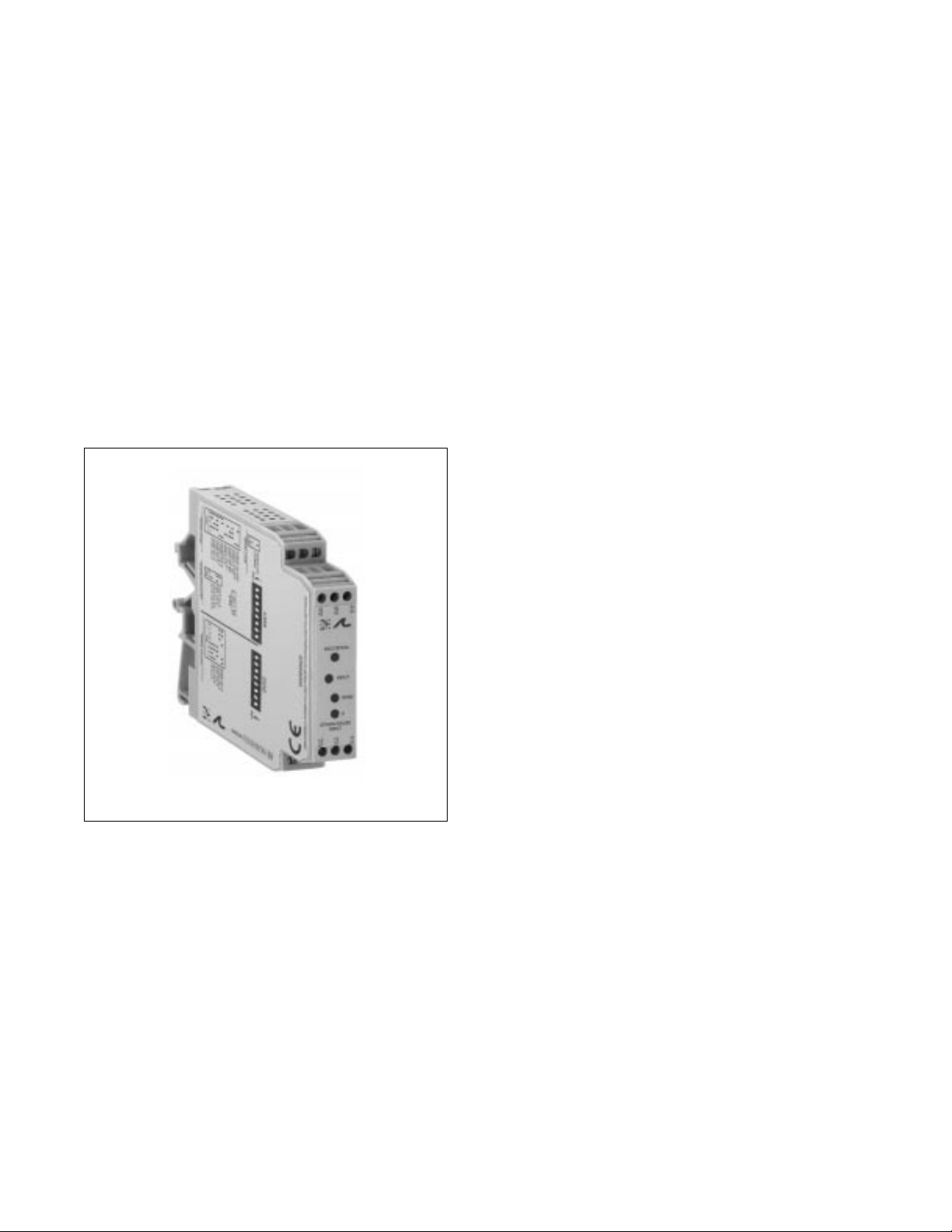
Electronic Interface Modules
G448 Ultra SlimPak®
Bridge/Strain Gauge Input,
Field Configurable Input Isolator
• field configurable via DIP switches for different inputoutput combinations
• provides an isolated, DC output in proportional to a
bridge/strain gauge input
• adjustable bridge excitation 1 to 10V with up to
120mA drive
• 11 field configurable input ranges from ±10mV to
±200mV (0.5mV/V to >50mV/V)
• 5 field configurable output ranges 0-5V, 0-10V, 0-1mA
0-20mA and 4-20mA
• flexible power supply accepts 18 to 30Vdc
• ASIC technology for high reliability
• 3 port isolation 1800Vdc between input to output
power
• CSA approved, UL recognized, CE marked
Page 2
Description
Application
Diagnostic LEDs
The Ultra SlimPak G448 is a DIN rail mount, bridge or strain gauge input signal conditioner with 1800Vdc
isolation between input, output and power. The field configurable input and output offers flexible, wide
ranging capability for bridge or strain gauge input applications from 0.5mV/ V to over 50mV/V.
Wide ranging, precision zero and span pots allow 50% adjustablity of offset and gain within each of the 11
switch selectable input ranges. The output can be set for either 0-5V, 0-10V, 0-1mA, 0-20mA or 4-20mA.
This flexibility, combined with an adjustable (1 to 10Vdc) bridge ex-citation source, provides the user a
reliable, accurate instrument to isolate and condition virtually any bridge or strain gauge input.
The Ultra SlimPak G448 field configurable, bridge input signal conditioner is useful in isolating ground loops
and interfacing bridge sensors to data acquisition and control systems.
Three way isolation completely eliminates ground loops from any source. Isolation protects expensive
SCADA systems from ground faults and provides filtering for noise reduction which can be a significant
problem with small, millivolt, bridge signals.
Wide ranging flexibility allows the user to easily zero out dead-loads in weighing systems or configure bipolar
input ranges for expansion-compression or vacuum-pressure bridge applications.
High density DIN rail mounting offers an extremely compact solution for saving valuable panel space.
The G448 is equipped with a dual function LED signal monitor. The green, front mounted LED indicates both
DC power and input signal status. Active DC power is indicated by an illuminated LED. If the input signal is
more than 110% of the full-scale range, the LED will flash at 8Hz. If this continues to occur, you may wish to
change your full-scale input range setting.
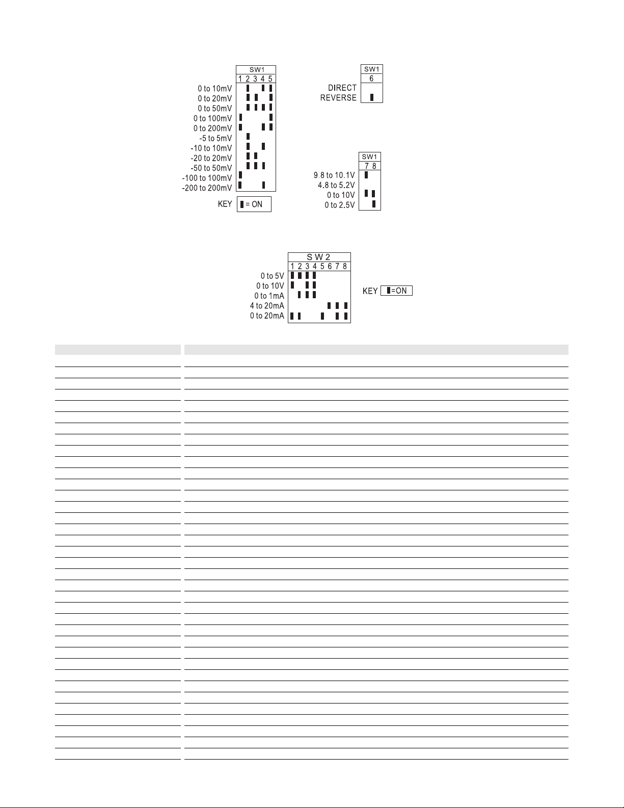
Table 3:
Bridge excitation
selector-switch settings
Table 2:
Direct or reverse
operation setting
Table 1:
Input range selectorswitch settings
Table 4:
Output range
selector-swtich
settings
Page 3

A major advantage of the G448 is its wide ranging capabilities and ease of configuration. The G448 has 11
input range switch settings. Trim potentiometers allow 50% input zero and span adjustablity within each of
the 11 full-scale, input ranges.
For example, the 200mV switch setting in Table 1 configures the input for a 0 to 200mV range. Since the
span can be contracted by 50%, this enables an input span as narrow as 100mV of the range, or 50%. This
span can be positioned anywhere within the 0-200mV range with a zero offset as large as 50% of the full
scale range (e.g. 100 to 200mV input). Unless otherwise specified, the factory presets the Model G448 as
follows:
Input Setting: 0 to 50mV
Input Range: 0 to 30mV (3mV/V)
Excitation: 10V
Operation: Direct
Output: 4 to 20mA
The DC power input accepts any DC source between 18 and 30V, typically a 24Vdc source is used.
For other I/O ranges refer to Tables 1 through 4 and reconfigure switches SW1 and SW2 for the desired
input range, function, excitation and output range.
Do not attempt to change any switch settings with power applied. Severe damage will result!
1. After configuring the DIP switches, connect the input to a calibrated millivolt source. Connect the output
to the actual device load (or a load equivalent to the actual device load value) and apply power. (see Wiring
Diagram).
NOTE: To maximize thermal stability, final calibration should be performed in the operating installation,
allowing approximately 1 to 2 hours for warm up and thermal equilibrium of the system.
2. Set the calibrator to the desired minimum and adjust the zero potentiometer for the desired minimum
output.
3. Set the calibrator to the desired maximum and adjust the span potentiometer for the desired maximum
output.
4. Repeat steps 2 and 3, if necessary for best accuracy.
5. Connect a calibrated voltmeter to the excitation output and adjust the excitation potentiometer to the
desired voltage output.
Configuration
WARNING:
Calibration
Page 4

Rated data
Input
Range
Impedance
Maximum ratings / type of protection
Field device excitation
Other input specification
Other input specification
Output
Range
Load
Burnout level
Zero / Span adjustment
Protection
Other output specification
Other output specification
Supply
Range
Consumption
Other supply specification
General
Accuracy
Linearity
Temperature coefficient (drift)
Transmission frequency
Response time. 90% span
Other general specification
Status LED
Isolation (# of ports)
Operating / Storage temperature
Housing (mounting)
Dimensions (L x W x H)
Wire range (conductor size)
Insulation stripping length
Tightening torque
Approvals
Ordering data
Ultra SlimPak
Heat sink (width)
Shunt resistor
Strain gauge, bridge or load cell device
±5mV to ±200mVdc, DIP switch selectable, direct or reverse operation
1MegM minimum
264Vdc maximum
1 to 10Vdc, 120mA maximum, DIP switch selectable
DC current or voltage
0-1mA, 0-20mA, 4-20mA, 0-5Vdc or 0-10Vdc, DIP switch selectable
<7.5kM (0-1mA), <600M (0/4-20mA), >500M (0-5V), >1000M (0-10V)
0 to 50% of full scale input, / 50 to 100% of full scale input
Noise: 0.1% of span, RMS or 10mV whichever is greater
DC voltage
18 to 30Vdc, inverter isolated
2.5W typ., (one 350M bridge), 4.0W max. (four 350M bridges in parallel)
±0.1% of selected input range at 25°C typ., 0.2% max.
included in accuracy
±0.025% of selected full scale input range/°C typical, ±0.05%/°C maximum
<200mS typical
input green (>110% of input; 8Hz, <0% of input: 4Hz)
1800V (3 port) between input, output and power
0°C to 55°C / -25°C to 70°C
EG12 (TS32 and TS35)
90mm x 17.7mm x 112.7mm max.
22-12AWG (0.5-4.0mm2)
7mm
0-4-0.8Nm
CSA (file LR-42272), UL (file E99775), CE marked (EMC dir. 89/336/EEC, LV dir. 73/23/EEC)
Cat.No.
G448 (factory calibration: 0-30mV In, 10Vdc Exc., direct operation, 4-20mA Out)
HS01-A (1.6mm) (conditionally required depending on installation, see heat sink data)
Note: G448-000X where X is the revision level
Specifications subject to change without notice. 99990008 - 8/98 Printed in Canada
TS32 RAIL
TS35 RAIL
 Loading...