

Page 1
Weidmuller Ltd.
10 Spy Court
Markham, ON L3R 5H6
Tel: (905)475-1507
Fax: (905)475-5855
Weidmuller Inc.
821 Southlake Blvd.
Richmond, VA 23236 U.S.A.
Tel: (804)794-2877
Fax: (804)794-0252
ISO 9001 Registered
Electronic Interface Modules
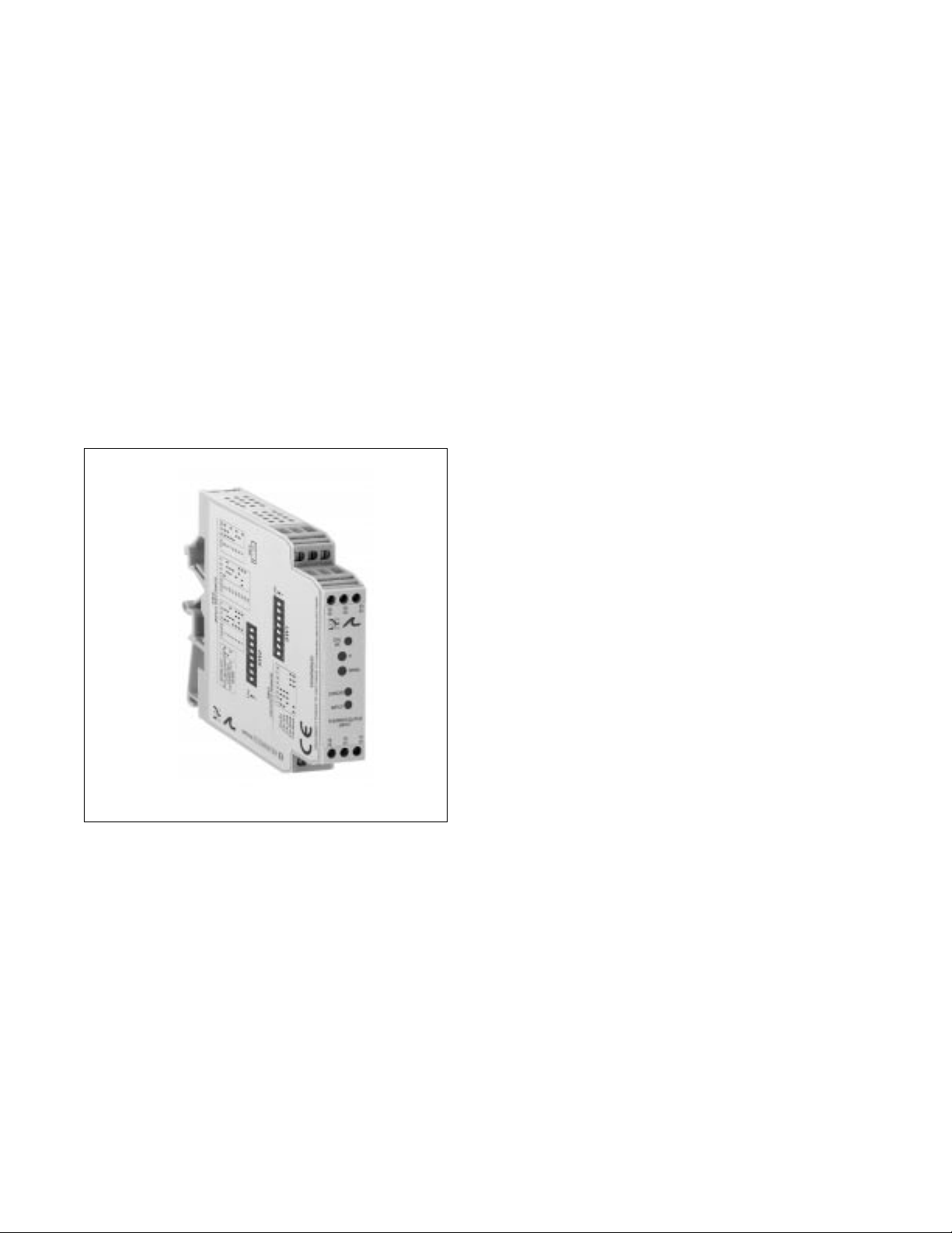
G428 Ultra SlimPak®
Thermocouple Input,
Field Configurable Isolator
• field configurable via DIP switches for different inputoutput combinations
• provides an isolated, DC output in proportional to the
thermocouple input
• output is linearised to temperature
• provide 3 port isolation to 1800Vdc between input,
output and power supply
• field configurable input ranges for J,K,T,R,S,E & B
type thermocouples
• field configurable output ranges 0-5V, 0-10V, 0-1mA
0-20mA and 4-20mA
• dual power terminals for daisy chain capability
• 9 to 30Vdc powered
• CSA approved, UL recognized, CE marked
Page 2
Description
Application
Diagnostic LEDs
Input LED
CAL OK LED
Troubled LED
The G428 is a DIN rail mount, thermocouple input signal conditioner with 1800Vdc isolation between input,
output and power. The field configurable input and output offer flexible, wide ranging capability for J, K, T, R,
S, E and B type thermocouples.
The input of the G428 can be configured for over 60 different thermocouple temperature ranges (see
Table 6). The output is linear to temperature and can be set for either 0-5V, 0-10V, 0-1mA, 0-20mA or
4-20mA.
Wide ranging, precision zero and span pots allow 50% adjustablity of offset and span turn-down within each
of the ranges. For example, the 0-1000°C range could be offset and turned down to provide a 4-20mA
signal representing 500-1000°C. Similarly, adjustment can be referenced to the output range. The example
from above could be used to provide a 12-20mA signal from a 750 to 1000°C temperature input.
The G428 field configurable thermocouple input isolator is useful in eliminating ground loops and interfacing
thermocouple sensors to data acquisition and control systems.
Three way isolation completely eliminates ground loops from any source. Isolation protects expensive
SCADA systems from ground faults and allows the noise reduction benefits of grounded thermocouples to
be realized.
The G428 employs the latest in advanced analog signal processing technology. In addition to its multiple
microprocessors, a special ASIC chip is used for high accuracy and reliability. The G428 is also equipped
with cold junction compensation (CJC) circuitry to provide ice-point reference. Upscale or downscale
thermocouple burnout detection is switch selectable. High density DIN rail mounting offers an extremely
compact solution to save valuable panel space.
The G428 is equipped with front panel LEDs for INPUT (green), TROUBLE (yellow) and CAL OK (yellow). At
start-up, both the INPUT and the CAL OK LEDs flash alternately for 10 seconds while start-up takes place.
This green LED is lit continuously when the input is within the specified range. In the full temperature range
setting, for the over range condition the LED flashes at 8Hz, whereas for the under range condition it flashes
at 4Hz. In a sub-range temperature setting, for the over range condition the LED flashes at 1Hz, whereas for
the under range condition it flashes at 0.5Hz.
This yellow LED is continuously on when the device is calibrated.
This yellow LED is off during the normal operation of the device. Consult factory if this LED is on, indicating
a microprocessor malfunction.
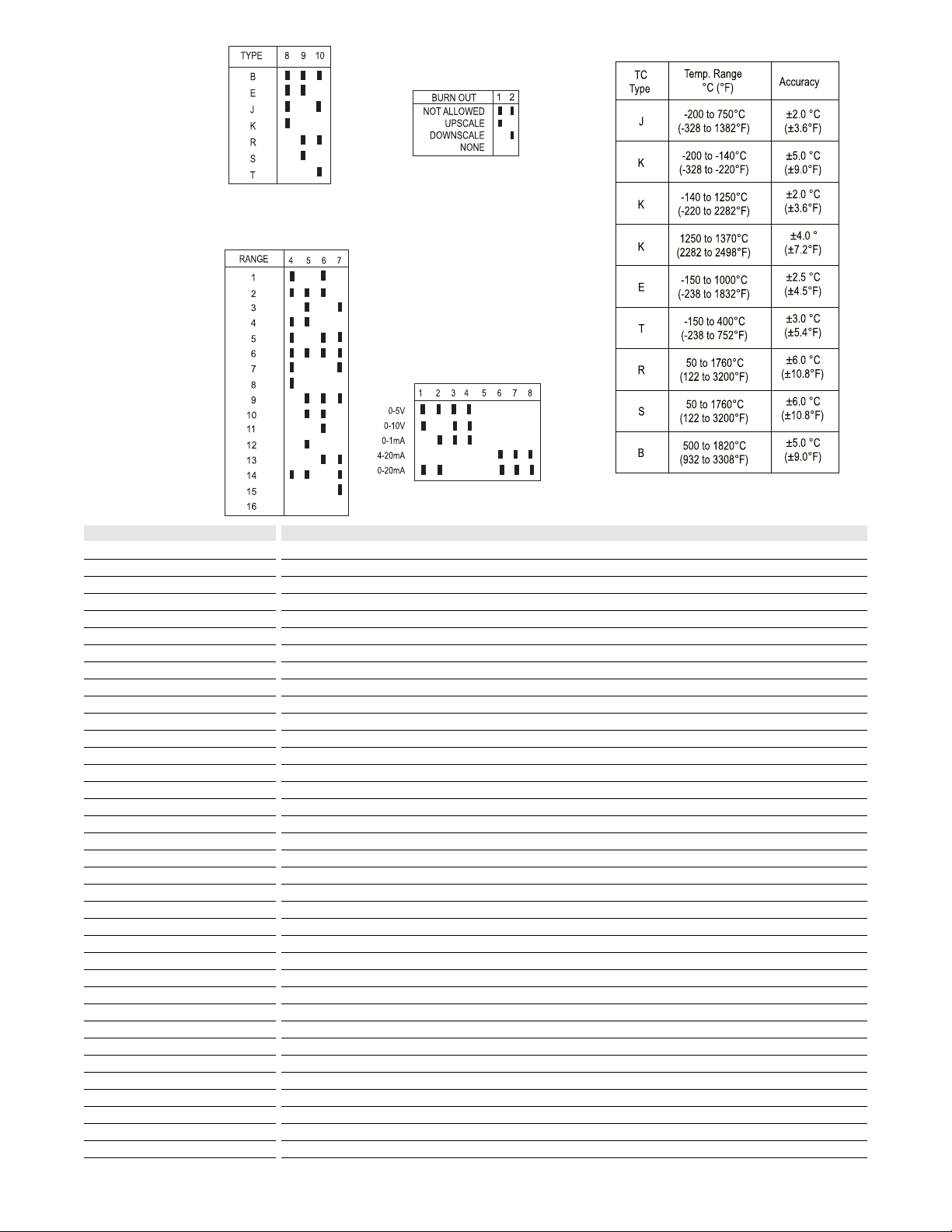
Table 2:
Range switch settings used
in conjuction with Table 6
(SW2, positions 4,5,6 and 7
Table 1:
Thermocouple type switch
settings (SW2, position 8, 9,
10)
Table 4:
Output switch settings
(SW1, position 1-8)
Table 5: Accuracy
Table 3:
Thermocouple burnout detection
switch settings (SW2, position 1, 2)
Note: SW2 position 3 is not used.
Key: n ON
Page 3

A major advantage of the G428 is its wide ranging capabilities
and ease of configuration. The G428 offers 50% input zero and
span adjustablity within each of the fullscale input ranges.
Unless otherwise specified, the factory presets the Model G428
as follows:
Input: J-type Range: 0 to 500°C
Output: 4 to 20mA Burn Out: Upscale
The DC power input accepts any DC source between 9 and 30V;
typically a 12V or 24Vdc source is used. For other I/O ranges
refer to Tables 1 through 6 and reconfigure switches SW1 and
SW2 for the desired input type range and output.
Do not attempt to change any switch settings with power
applied. Severe damage will result!
1. Choose the desired temperature range from table 6, then use
table 1 and 2 to configure the switches, as described in the
following steps, for thermocouple type and range.
2. With DC power off, position input switches 1 and 2 on "SW2"
for the desired burnout detection mode.
3. Set positions 4 through 10 on "SW2" for the desired
thermocouple range and type.
4. Set positions 1 through 8 of output range switch "SW1" for the
desired output signal. (Table 4)
1. After configuring the dip switches, connect the input to a
calibrated thermocouple source. Connect the output to the
actual device load (or a load approximately equivalent to the
actual device load value) and apply power.
NOTE: To maximize thermal stability, final calibration should be
performed in the operation installation, allowing approximately 1
to 2 hours for warm up and thermal equilibrium of the system.
2. Set the calibrator to the desired minimum input and adjust the
zero potentiometer for the desired minimum output.
3. Set the calibrator to the desired maximum input and adjust the
span potentiometer for the desired maximum output.
4. Repeat steps 2 and 3, if necessary for best accuracy.
Configuration
WARNING
Calibration
Table 6:
Thermocouple range settings
TC TYPE
B
E
JJ
K
R,S
T
RANGE
6
7
8
11
12
2
3
4
5
8
9
10
12
13
14
15
16
2
3
4
5
8
9
10
13
14
15
16
1
2
3
4
5
7
8
9
10
12
13
14
15
16
1
2
3
4
7
8
9
10
11
12
13
3
4
5
9
10
13
14
15
16
TEMPERATURERANGE
500°C to 1820°C (932 to 3308°F)
1000°C to 1820°C( 1832 to 3308°F)
500°C to 1000°C (932 to 1832°F)
1500°C to 1820°C (2732 to 3308°F)
750°C to 1000°C (1382 to 1832°F)
-18°C to 1000°C (0 to 1832°F)
-18°C to 500°C (0 to 932°F)
-18°C to 250°C (0 to 482°F)
-18°C to 125°C (0 to 257°F)
500°C to 1000°C (932 to 1832°F)
250°C to 500°C (482 to 932°F)
125°C to 250°C (257 to 482°F)
750°C to 1000°C (1382 to 1832°F)
375°C to 500°C (707 to 932°F)
-150°C to 750°C (-238 to 1382°F)
-150°C to 250°C (-238 to 482°F)
-150°C to 0°C (-238 to 32°F)
-18°C to 750°C (0 to 1382°F)
-18°C to 500°C (0 to 932°F)
-18°C to 250°C (0 to 482°F)
-18°C to 125°C (0 to 257°F)
500°C to 750°C (932 to 1382°F)
250°C to 500°C (482 to 932°F)
125°C to 250°C (257 to 482°F)
375°C to 500°C (707 to 932°F)
-200°C to 750°C (-328 to 1382°F)
-200°C to 250°C (-328 to 482°F)
-200°C to 0°C (-328 to 32°F)
-18°C to 1370°C (0 to 2498°F)
-18°C to 1000°C (0 to 1832°F)
-18°C to 500°C (0 to 932°F)
-18°C to 250°C (0 to 482°F)
-18°C to 125°C(0 to 257°F)
1000°C to 1370°C (1832 to 2498°F)
500°C to 1000°C (932 to 1832°F)
250°C to 500°C (482 to 932°F)
125°C to 250°C (257 to 482°F)
750°C to 1000°C (1382 to 1832°F)
375°C to 500°C (707 to 932°F)
-200°C to 750°C (-328 to 1382°F)
-200°C to 250°C (-328 to 482°F)
-200°C to 0°C (-328 to 32°F)
50°C to 1760°C (122 to 3200°F)
50°C to 1000°C (122 to 1832°F)
50°C to 500°C (122 to 932°F)
50°C to 250°C (122 to 482°F)
1000°C to 1760°C (1832 to 3200°F)
500°C to 1000°C (932 to 1832°F)
250°C to 500°C (482 to 932°F)
125°C to 250°C (257 to 482°F)
1500°C to 1760°C (2732 to 3200°F)
750°C to 1000°C (1382 to 1832°F)
375°C to 500°C (707 to 932°F)
-18°C to 400°C (0 to 752°F)
-18°C to 250°C (0 to 482°F)
-18°C to 125°C (0 to 257°F)
250°C to 400°C (482 to 752°F)
125°C to 250°C (257 to 482°F)
375°C to 400°C (707 to 752°F)
-150°C to 400°C (-238 to 752°F)
-150°C to 250°C (-238 to 482°F)
-150°C to 0°C (-238 to 32°F)
Page 4

Rated data
Input
Range
Impedance
Maximum ratings / type of protection
Other input specification
Output
Range
Load
Burnout level
Zero / Span adjustment
Supply
Range
Consumption
General
Accuracy
Temperature coefficient (drift)
Response time. 90% span
Status LED
Isolation (# of ports)
Operating / Storage temperature
Housing (mounting)
Dimensions (L x W x H)
Wire range (conductor size)
Insulation stripping length
Tightening torque
Approvals
Ordering data
Ultra SlimPak
Heat sink (width)
Shunt resistor
Thermocouple temperature sensor
Thermocouple Type Material Temperature Range
B PtRh-PtRh +500...+1820°C
E NiCr-CuNi -150...+1000°C
J Fe-CuNi -200...+750°C
K NiCr-Ni Al -200...+1370°C
R PtRh-Pt +50...+1760°C
S PtRh-Pt +50...+1760°C
T Cu-CuNi -150...+400°C
DIP switch selectable
1 MegM min.
±10Vdc
input bias current: <1.5HA
DC current or voltage
0-1mA, 0-20mA, 4-20mA, 0-5Vdc or 0-10Vdc, DIP switch selectable
<7.5kM (0-1mA), <600M (0/4-20mA), >500M (0-5V), >1000M (0-10V)
DIP switch selectable: upscale, downscale or disable
0 to 50% of full scale input / 50 to 100% of full scale input
DC voltage
9 to 30Vdc, inverter isolated
1.5W typ., 2.5W max. (300mA inrush at 9Vdc)
±2°C (type J, K (-140 to 1250°C)), ±2.5°C (type E), ±3.0°C (type T), ±4.0°C (type K (1250 to 1370°C)),
±5.0°C (type B, K (-200 to -140°C)), ±6.0°C (type R, S)
±0.04% of maximum full scale/°C change in ambient temperature, maximum
<500mS typical
input green (0<no flash<100% of input, flash otherwise), calibration yellow (ON=OK), trouble yellow (OFF=OK)
1800V (3 port) between contacts, input and power
0°C to 55°C / -25°C to 70°C
EG12 (TS32 and TS35)
90mm x 17.7mm x 112.7mm max.
22-12AWG (0.5-4.0mm2)
7mm
0.4-0.8Nm
CSA (file LR-42272), UL (file E99775), CE marked (EMC dir. 89/336/EEC, LV dir. 73/23/EEC)
Cat. No.
G428 (factory calibration: 0 to 500ºC (J-type) In, 4-20mA Out, upscale)
HS01-A (1.6mm) (conditionally required depending on installation, see heat sink data)
Note: G428-000X where X is the revision level
Specifications subject to change without notice. 99990004 - 8/98 Printed in Canada
TS32 RAIL
TS35 RAIL
 Loading...