

Page 1
Weidmuller Ltd.
10 Spy Court
Markham, ON L3R 5H6
Tel: (905)475-1507
Fax: (905)475-5855
Weidmuller Inc.
821 Southlake Blvd.
Richmond, VA 23236 U.S.A.
Tel: (804)794-2877
Fax: (804)794-0252
ISO 9001 Registered
Electronic Interface Modules
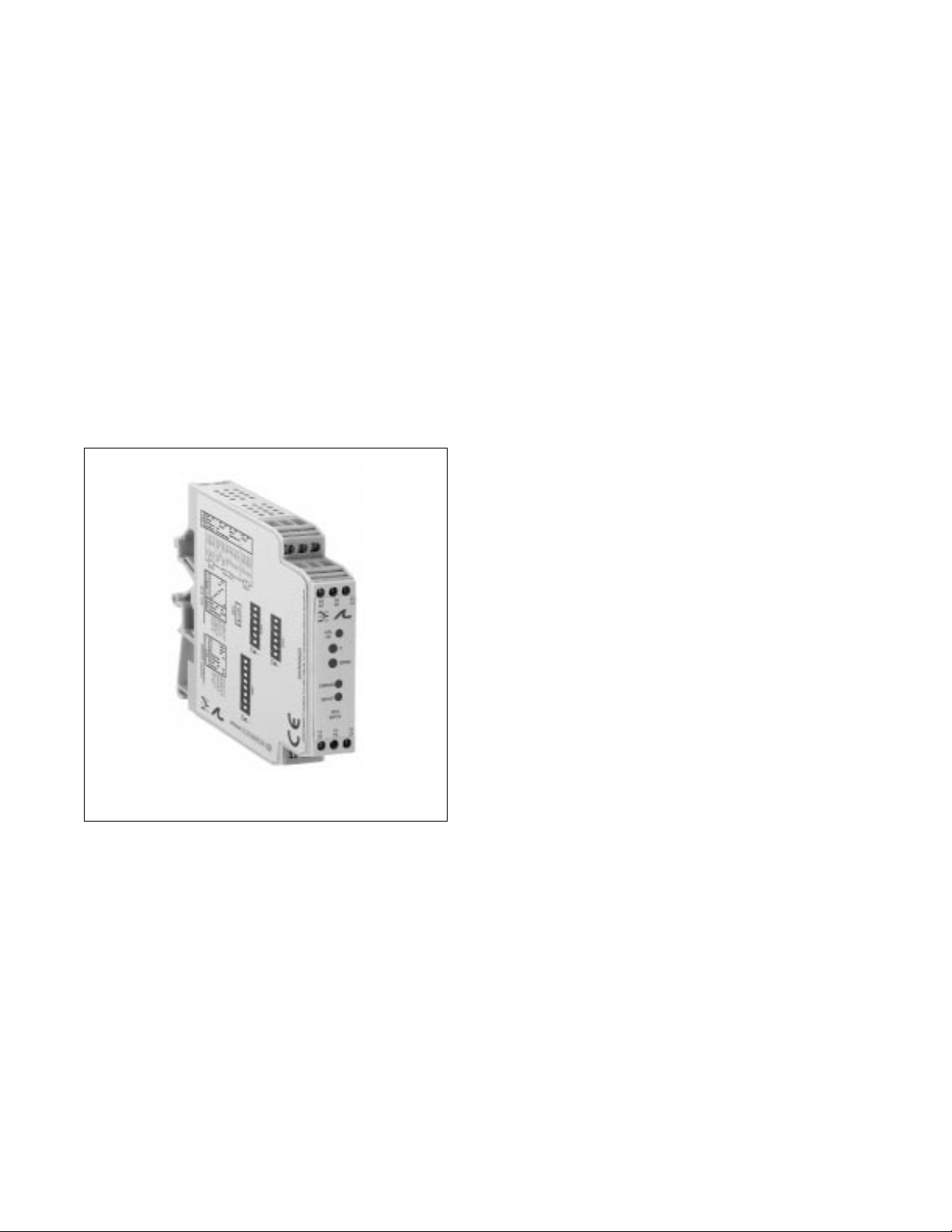
G418 Ultra SlimPak®
RTD Input, Field Configurable Isolator
• field configurable via DIP switches for different inputoutput combinations
• provides an isolated, linearised DC output
• output is linearized to temperature
• 3 port isolation to 1800Vdc between input, output and
power supply
• 5 field configurable output ranges 0-5V, 0-10V, 0-1mA
0-20mA, 4-20mA
• 9 to 30Vdc powered
• CSA approved, UL recognized, CE marked
Page 2
Description
Application
Diagnostic LEDs
The Ultra SlimPak G418 is a DIN rail mount, RTD input signal conditioner with 1800Vdc isolation between
input, output and power. The field configurable input and output offers flexible, wide ranging capability
for Platinum and Copper RTDs.
The input of the G418 Ultra SlimPak can be configured for any one of up to sixteen temperature ranges (see
Tables 1 & 2). The output is linear to the RTD temperature input and can be set for either 0-5V, 0-10V,
0-1mA, 0-20mA or 4-20mA.
Wide ranging, precision zero and span pots allow 50% adjustablity of offset and span turn-down within
each of the sixteen switch selectable. ranges. For example, the 0-500°F range could be offset and turned
down to provide a 4-20mA signal representing 0-250°F (or 250-500°F).
The Ultra SlimPak G418 field configurable RTD input isolator is useful in eliminating ground loops and
interfacing RTD sensors to data acquisition and control systems. Three way isolation completely eliminates
ground loops from any source. Isolation protects expensive SCADA systems from ground faults and
significantly reduces the effect of high common mode voltages which are prevalent in many RTD
applications.
The constant current RTD excitation circuitry uses the third lead of the RTD to sense and compensate for
the RTD lead resistance, resulting in an accurate RTD temperature measurement.
High density DIN rail mounting offers an extremely compact solution for saving valuable panel space.
The G418 is equipped with a dual function LED signal monitor. The green, front mounted LED indicates
both DC power and input signal status. Active DC power is indicated by an illuminated LED. If the input
signal is more than 110% of the full scale range, the LED will flash at 1Hz. Below -10%, the flash rate is
0.5Hz. If the LED flashes very fast, then the RTD input wires are open circuit. An 8Hz flash indicates that
RTD input (+), terminal 41, is open circuit, or a 4Hz flash indicates that either RTD (-) or RTD Return, terminal
42 or 43, are open. The CAL LED is on under normal operating conditions. If the CAL LED is off when the
unit is powered, consult the factory for assistance.
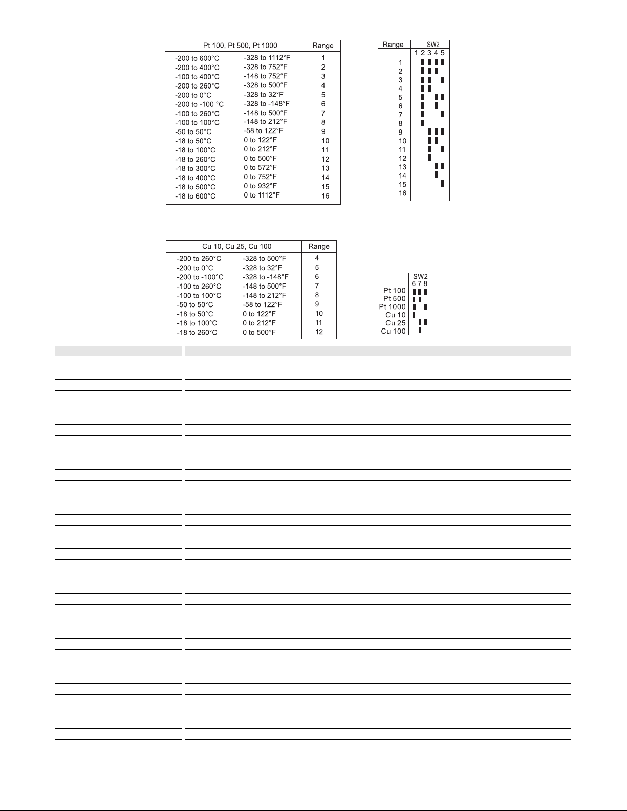
Table 1:
G418 Platinum RTD temperature
range
Table 3:
Temperature input range switch
settings (SW2 - 1 through 5)
Table 4:
RTD input range switch settings
(SW2 - 6 through 8)
Table 2:
G418 Copper RTD temperature
ranges
Key: n ON
Page 3

A major advantage of the G418 is its wide ranging capabilities and ease of configuration. The G418 has 16
input temperature range settings, six RTD type settings and five output range settings. Trim potentiometers
allow 50% input zero and span adjustability within each of the 16 full scale input ranges.
Unless otherwise specified, the factory presets the Model G418 as follows:
Input: Pt100M
Range: -200 to 600°C
Output: 4-20mA
The DC power input accepts any DC source between 9 and 30V; typically a 12V or 24VDC source is used.
In order to minimize interference from electrical and magnetic fields the use of shielded and twisted-pairs is
recommended for the input and output. For other I/O ranges, refer to Tables 1 through 6 and reconfigure
switches SW1, SW2 and SW3 for the desired input type, range and output.
Do not attempt to change any switch settings with power applied. Severe damage will result!
1. Choose the desired temperature range from table 1 or 2 depending on RTD type.
2. With DC power off, position input switches 1 through 5 on "SW2" for the desired temperature range
(Table 3).
3. Set position 6 through 8 of input range switch "SW2" for the desired RTD type (Table 4).
4. Set position 1 through 8 of excitation switch "SW3" for the desired RTD type (Table 5).
5. Set position 1 through 8 of output range switch "SW1" for the desired output signal (Table 6).
1. After configuring the dip switches, connect the input to a calibrated RTD source or decade resistance
box. Connect the output to the actual device load (or a load approximately equivalent to the actual device
load value) and apply power.
Note: To maximize thermal stability, final calibration should be performed in the operating installation,
allowing approximately 1 to 2 hours for warm up and thermal equilibrium of the system.
2. Set the calibrator to the desired minimum temperature and adjust the zero potentiometer for the
desired minimum output.
3. Set the calibrator to the desired maximum temperature and adjust the span potentiometer for the desired
maximum output.
4. Repeat steps 2 and 3, as necessary for best accuracy.
Configuration
WARNING:
Calibration
Table 5:
Excitation type switch settings
(SW3 - 1 through 8)
Table 6:
Output switch settings
(SW1 - 1 through 8)
Key: n ON
Page 4

Rated data
Input
Range
Impedance
Maximum ratings / type of protection
Field device excitation
Other input specification
Other input specification
Output
Range
Load
Burnout level
Zero / Span adjustment
Protection
Other output specification
Other output specification
Supply
Range
Consumption
Other supply specification
General
Accuracy
Temperature coefficient (drift)
Transmission frequency
Response time. 90% span
Status LED
Isolation (# of ports)
Operating / Storage temperature
Housing (mounting)
Dimensions (L x W x H)
Wire range (conductor size)
Insulation stripping length
Tightening torque
Approvals
Ordering data
Ultra SlimPak
Heat sink (width)
Shunt resistor
RTD temperature sensor, 3 wire
-200 to 600°C for Pt100/Pt500/Pt1000, -200 to 260°C for Cu10/Cu25/Cu100, DIP switch selectable
<2mA for Pt100, Pt500, Pt1000; <5mA for Cu100; <10mA for Cu10, Cu25
leadwire resistance: 40% of base sensor resistance or 100M (whichever is less), max. per lead
leadwire effect: less than 1% of selected span over entire leadwire resistance range
DC current or voltage
0-1mA, 0-20mA, 4-20mA, 0-5Vdc or 0-10Vdc, DIP switch selectable
<7.5kM (0-1mA), <600M (0/4-20mA), >500M (0-5V), >1000M (0-10V)
0 to 50% of full scale input / 50 to 100% of full scale input
DC voltage
9 to 30Vdc, inverter isolated
1.5W typ., 2.5W max. (300mA inrush at 9Vdc)
±0.1% of the max. input temperature range configurable for the RTD type, 0.2% max., at 25°C ambient and
0M lead resistance
±0.015% of the maximum input temperature range for the RTD type/°C change in ambient temperature, max
<200mS typical
input green (>110% of input: 1Hz, <-10% of input: 0.5Hz, open circuit on input +: 8Hz, open circuit on RTN
or input -: 4Hz); calibration yellow (ON=OK)
1800V (3 port) between input, output and power
0 to 55°C / -25 to 70°C
EG12 (TS32 and TS35)
90mm x 17.7mm x 112.7mm max.
22-12AWG (0.5-4.0mm2)
7mm
0.4-0.8Nm
CSA (file LR-42272), UL (file E99775), CE marked (EMC dir. 89/336/EEC, LV dir. 73/23/EEC)
Cat. No.
G418 (factory calibration:-200 to 600°C (Pt100) In, 4-20mA Out)
HS01-A (1.6mm) (conditionally required depending on installation, see heat sink data)
Note: G418-000X where X is the revision level. For 2 wire sensors: connect RTN and - externally.
Specifications subject to change without notice. 99990007 - 8/98 Printed in Canada
TS32 RAIL
TS35 RAIL
 Loading...