

Page 1
Weidmuller Ltd.
10 Spy Court
Markham, ON L3R 5H6
Tel: (905)475-1507
Fax: (905)475-5855
Weidmuller Ltd
821 Southlake Blvd.
Richmond, VA 23236 U.S.A.
Tel: (804)794-2877
Fax: (804)794-0252
ISO 9001 Registered
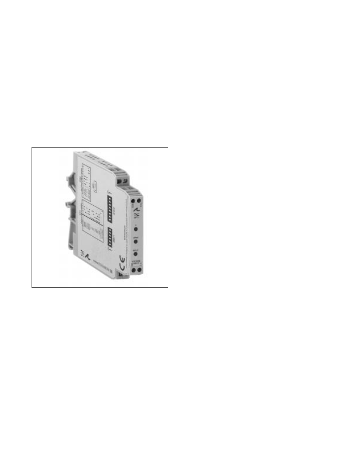
Electronic Interface Modules
G408 Ultra SlimPak®
DC Input, Field Configurable Isolator
• field configurable via DIP switches for different inputoutput combinations
• eliminates ground loops and isolates to 1800Vdc
between input, output and power
• field configurable input ranges 10mV to 100V, 1mA to
100mA
• field configurable output ranges 0-10V, 0-5V, 0-20mA,
4-20mA, 0-1mA
• ultra slim package 12.7mm
• 9 to 30Vdc powered
• CSA approved, UL recognized, CE marked
Page 2
Description
Application
Diagnostic LEDs
The Ultra SlimPak G408 is a DIN rail mount, DC input signal conditioner with 1800Vdc isolation between
input, output and power. The field configurable input and output offers flexible, wide ranging capability for
DC current and voltage signals.
The input of the G408 Ultra SlimPak can be configured for any one of 12 voltage ranges from 10mV to 100V
or 6 current ranges from 1mA to 100mA (see table 1). The output is linear to the input and can be set for
0-5V, 0-10V, 0-1mA, 0-20mA or 4-20mA .
Wide ranging, precision zero and span pots allow 50% adjustability of offset and span turn-down within each
of the 18 switch selectable ranges. For example, the 0-2mA input range could be turned down to 0-1mA
and provide a full scale output signal (e.g. 4-20mA), or turned down and offset to achieve a 1-2mA/4-20mA
I/O combination.
The G408 also accepts bipolar inputs (e.g. 10V range set to bipolar = -10 to +10V) and offers selectable
normal, or reverse operation (e.g. 4-20mA/20-4mA). The ASIC based I/O channel is optically isolated to
1800Vdc and is transformer isolated from the power supply.
The Ultra SlimPak G408 field configurable isolator is useful in eliminating ground loops, converting signal
levels, and providing signal drive. The field configurable, wide ranging capability ensures maximum flexibility
for most DC to DC applications, minimizing spare part requirements.
The G408 is equipped with a dual function LED signal monitor. The green, front mounted LED indicates both
DC power and input signal status. Active DC power is indicated by an illuminated LED. If the input signal is
more than 110% of the full scale range, the LED will flash at 8Hz. Below -10%, the flash rate is 4Hz.
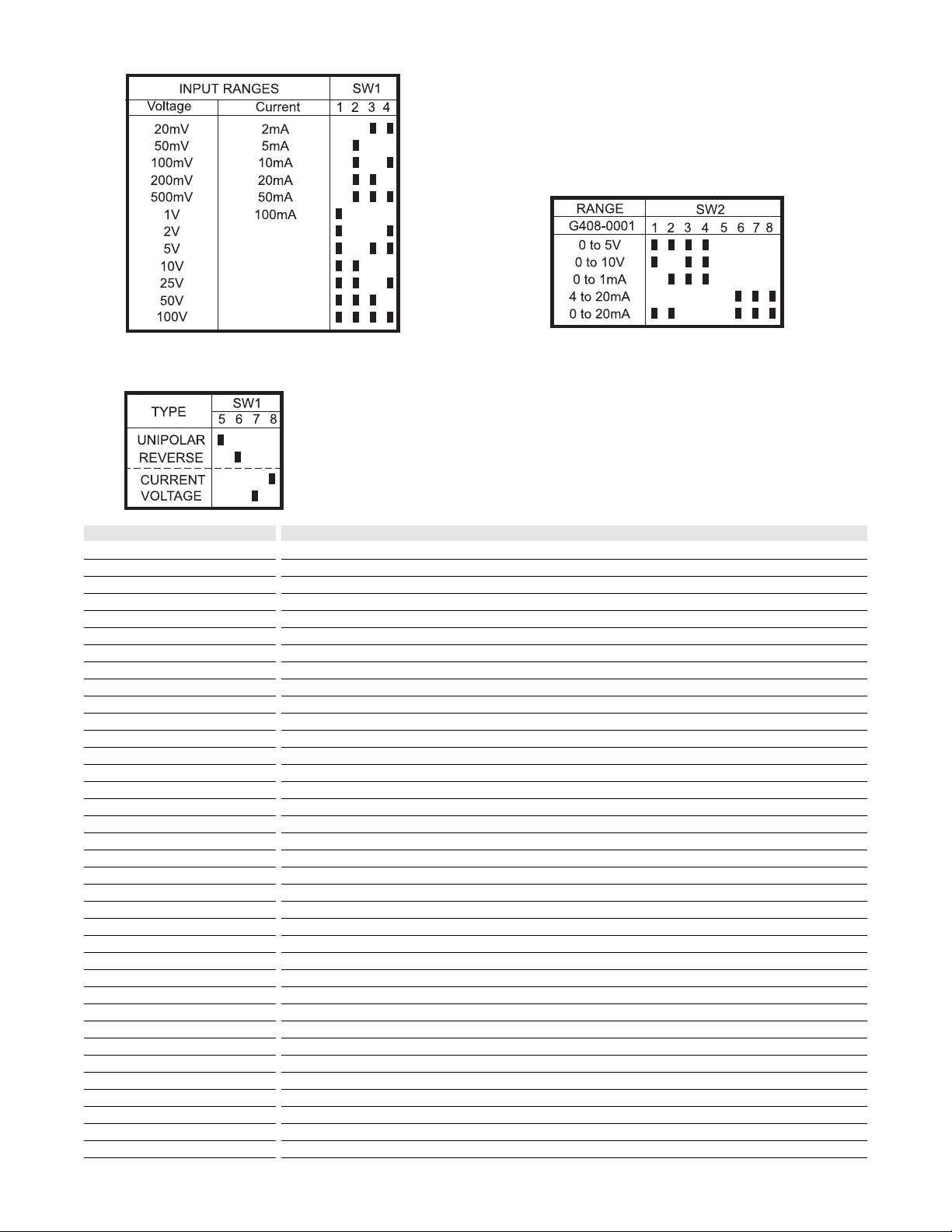
Table 1: G408 input range selector - switch settings
Key: n ON
Table 3: Output range selector - switch settings
Table 2:
Input range and
function settings
Page 3

A major advantage of the G408 is its wide ranging capability and ease of configuration. The G408 has 18
input range settings. Trim potentiometers allow 50% input zero and span adjustability within each of the 18
full scale input ranges. Unless otherwise specified, the factory presets the Model G408 as follows:
Input Range: 4-20mA Output Range: 4-20mA
The DC power input accepts any source between 9 and 30V; typically a 12V or 24Vdc source is used
To minimize interference from electrical and magnetic fields, the use of shielded, twisted pair wires on the
input and output is recommended.
Do not attempt to change any switch settings with power applied. Severe damage will result!
Refer to Tables 1 through 3 for the proper switch settings. Use the switches on SW1 to select the input type
(voltage or current) and also to select the desired input range and function setting. Use SW2 to select the
desired type of output.
1. After configuring the dip switches, connect the input to a calibrated DC source. Connect the output to the
actual device load (or a load approximately equivalent to the actual device load value) and apply power.
Note: To maximize thermal stability, final calibration should be performed in the operating installation, allowing
approximately 1 to 2 hours for warm up and thermal equilibrium of the system.
2. Set the calibrator to the desired minimum input and adjust the zero potentiometer for the desired
minimum output.
3. Set the calibrator to the desired maximum input and adjust the span potentiometer for the desired
maximum output.
4. Repeat steps 2 and 3, as necessary, for best accuracy.
Configuration
WARNING
Calibration
Page 4

Rated data
Input
Range
Impedance
Maximum ratings / type of protection
Field device excitation
Other input specification
Other input specification
Output
Range
Load
Burnout level
Zero / Span adjustment
Protection
Other output specification
Other output specification
Supply
Range
Consumption
Other supply specification
General
Accuracy
Temperature coefficient (drift)
Transmission frequency
Response time. 90% span
Other general specification
Status LED
Isolation (# of ports)
Operating / Storage temperature
Housing (mounting)
Dimensions (L x W x H)
Wire range (conductor size)
Insulation stripping length
Tightening torque
Approvals
Ordering data
Ultra SlimPak
Heat sink (width)
Shunt resistor
DC current or voltage
±1mA to ±100mA or ±10mVdc to ±100Vdc, DIP switch selectable
20M for current, >100kM for voltage
170mA, 60Vdc for current, 264Vrms for voltage
DC current or voltage
0-1mA, 0-20mA, 4-20mA, 0-5Vdc or 0-10Vdc, DIP switch selectable
<7.5kM (0-1mA), <600M (0/4-20mA), >500M (0-5V), >1000M (0-10V)
0 to 50% of full scale input / 50 to 100% of full scale input
DC voltage
9 to 30Vdc, inverter isolated
1.5W typ., 2.5W max. (200mA inrush at 9Vdc)
±0.35% of full typ., 0.5% max (span <2mA or <20mA) or ±0.1% of full scale typ., 0.2% max. (span >2mA or
>20mV)
±0.025% of full scale/°C typical, ±0.05%/°C maximum
<200mS typical
Mean Time Before Failure: 60kHours
input green (>110% of input: 8Hz, <-10% of input: 4Hz)
1800V (3 port) between input, output and power
0 to 55°C / -25 to 70°C
EG8 (TS32 and TS35)
90mm x 12.7mm x 112.7mm max.
22-12AWG (0.5-4.0mm2)
7mm
0.4-0.8Nm
CSA (file LR-42272), UL (file E99775), CE marked (EMC dir. 89/336/EEC, LV dir. 73/23/EEC: Input <75Vdc only)
Cat. No.
G408 (factory calibration: 4-20mA In, 4-20mA Out)
HS01-A (1.6mm) (conditionally required depending on installation, see heat sink data)
C006 (0.1M, 1%, 5W for use with external DC current source)
Note: G408-000X where X is the revision level
Specifications subject to change without notice. 999992 - 8/98 Printed in Canada
12.6
110.2
TS32 RAIL
88.5
105.2
TS35 RAIL
90.0
 Loading...