

Page 1
Weidmuller Ltd.
10 Spy Court
Markham, ON L3R 5H6
Tel: (905)475-1507
Fax: (905)475-5855
Weidmuller Inc.
821 Southlake Blvd.
Richmond, VA 23236 U.S.A.
Tel: (804)794-2877
Fax: (804)794-0252
ISO 9001 Registered
Electronic Interface Modules
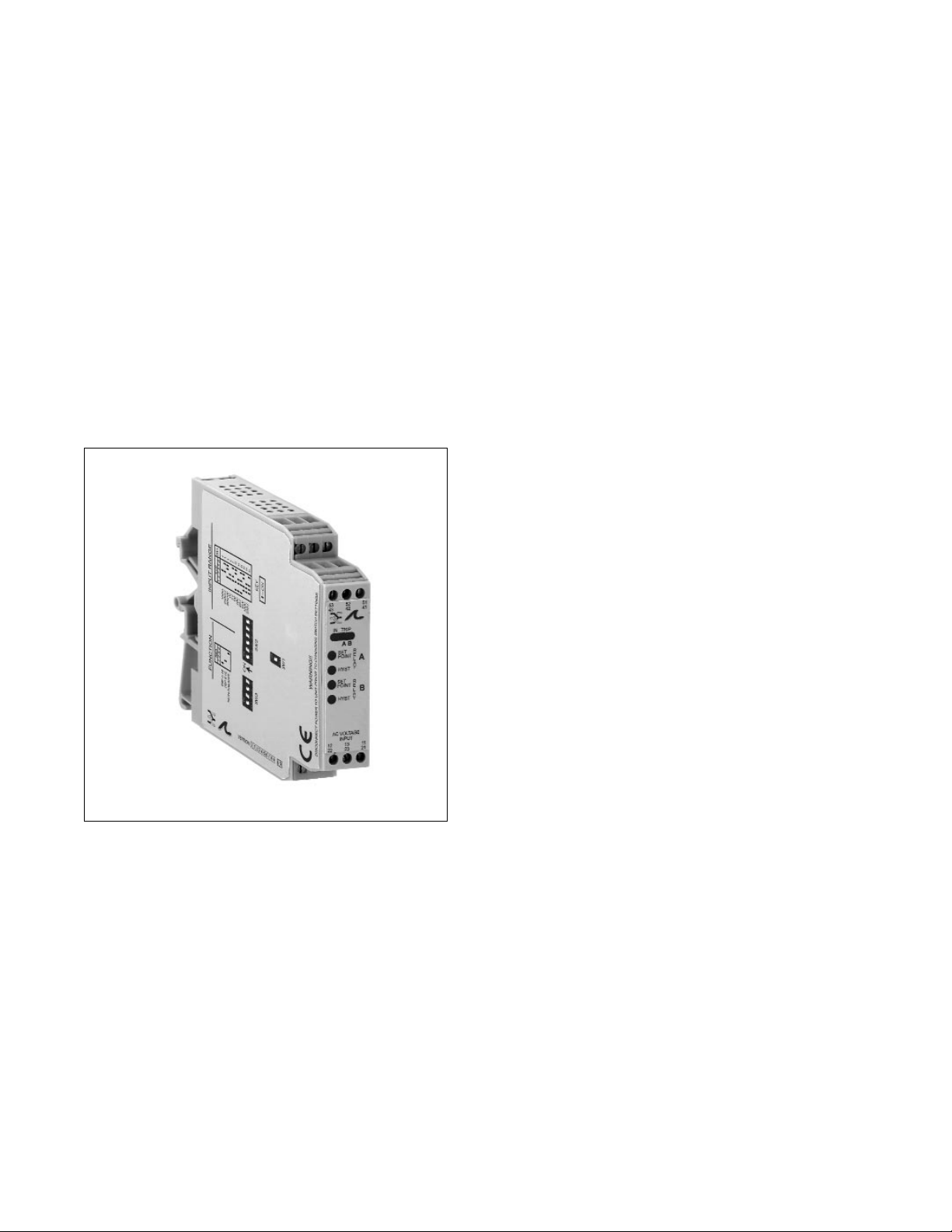
G168 Ultra SlimPak®
AC Input, Field Configurable Limit Alarm
• field configurable via DIP switches for different inputoutput combinations
• provides relay contact closure(s) at a preset AC input
level
• field configurable input ranges
• setpoints programmable HI or LO and failsafe or nonfailsafe
• LED trip and input indicators
• 9 to 30Vdc powered
• CSA approved, UL recognized, CE marked
Page 2
Description
Diagnostic LEDs
Output
Operation
Dynamic Deadband
The Ultra SlimPak G168 is a DIN rail mount, AC voltage or current input limit alarm with dual setpoints and
two contact closure outputs. The field configurable input and alarm functions offer flexible setpoint capability.
Input voltage spans from 100mV to 250Vac and input current spans from 10mA to 100mAac can be field
configured. For current input spans of 1 to 5 Amps a 0.1M (5W) shunt resistor (Model# C006) is available.
The G168 is configurable as a single or dual setpoint alarm, with HI or LO trips and failsafe or non-failsafe
operation. Also included are adjustable deadbands (0.25 to 5% of full scale input) for each setpoint. The
G168 will accept any DC voltage between 9 and 30Vdc.
The G168 is equipped with three front panel LEDs. The first is a dual function LED labeled IN (input). This
green LED indicates the presence of DC power and input signal status. Active DC power is indicated by an
illuminated LED. If this LED is off, check DC power and wiring connection. If the input signal is more than
110% of the full scale range, the LED will flash at 8 Hz.
Two red TRIP LEDs indicate the re-lay state for each setpoint. An illuminated red LED indicates the tripped
condition.
The G168 is equipped with two SPDT (form C) relays, rated at 120Vac or 28Vdc at 5 amperes. Each of
these relays is independently controlled by the field configurable setpoint and deadband.
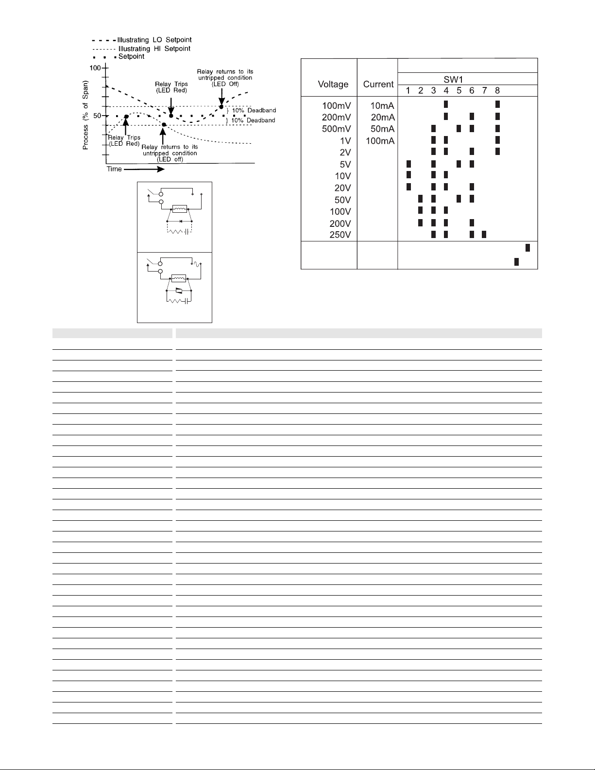
The field configurable G168 limit alarm setpoints can be configured for HI or LO, failsafe or non-failsafe
operation. Each of the setpoints have a respective HI or LO deadband. In a tripped condition, the setpoint
is exceeded and the appropriate red LED will illuminate. The trip will reset only when the process falls below
the HI deadband or rises above the LO deadband (see Figure 1). For proper deadband operation, the HI
setpoint must always be set above the LO setpoint.
In failsafe operation, the relay is energized when the process is below the HI setpoint or above the LO setpoint (opposite for non-failsafe). In the failsafe mode, a power failure results in an alarm state output.
LSI circuitry in the G168 prevents false trips by repeatedly sampling the input. The input must remain beyond
the setpoint for 100 milliseconds, uninterrupted, to qualify as a valid trip condition. Likewise, the input must
fall outside the deadband and remain there for 100 milliseconds to return the alarm to an untripped
condition. This effectively results in a "dynamic deadband" -based on time- in addition to the normal
deadband.
Table 1: G168 input range selector - switch settings
Key: n ON
Figure 1
+
Load
Relay
Conta cts
Diode
(optio nal)
Figure 2: DC Inductive Loads
Relay
Conta cts
Figure 3: AC Inductive Loads
47 ohm
1/2W
47 ohm
1/2W
Load
MOV
0.1uF
0.1uF
Film
Film
Power
Power
Input Range Selector
910
-
Current
Voltage
Page 3

Unless otherwise specified, the factory presets the Model G168 as follows:
Input: Voltage Range: 0-500mVac Output: Dual, SPDT
Trip: A:HI, B:LO Failsafe: No Deadband: A, B: 0.25%
The DC power input accepts any DC source between 9 and 30V, typically a 12V or 24Vdc source is used.
For other I/O ranges, refer to Table 1 and Figure 4 to reconfigure switches SW1 and SW2 for the desired
input type, range and function.
Do not attempt to change any switch settings with power applied. Severe damage will result!
1. With DC power off, position input switch "SW1-9,10" for voltage or current.
2. Set position 1 through position 8 of input range switch "SW1" for the desired input range (see Table 1).
3. Set position 1 and 2 of function switch "SW2" to ON for a HI trip setpoint or OFF for a LO trip
(see Figure 4).
4. Set position 4 of function switch "SW2" to ON for non-failsafe operation or OFF for failsafe operation (e.g.
alarm trips when power fails).
1. After configuring the dip switches, connect the input to a calibrated AC source and apply power. Refer to
the terminal wiring diagram.
NOTE: To maximize thermal stability, final calibration should be performed in the operation installation,
allowing approximately 1 to 2 hours for warm up and thermal equilibrium of the system.
2. Setpoint: set deadband at its minimum (fully counter-clockwise) before adjusting the setpoint. With the
desired trip voltage or current input applied, adjust setpoint until the relay trips. For HI trip calibration,
start with the setpoint above the desired trip (full clockwise). For LO trip calibration, start below the desired
trip (full counter-clockwise).
3. Deadband: Set deadband to its minimum (fully counter-clockwise). Set the setpoint to desired trip. Adjust
voltage/current input until relay trips. Readjust deadband to 5% (fully clockwise). Set voltage/current input
signal to desired deadband position. Slowly adjust deadband until relay untrips.
When switching inductive loads, maximum relay life and transient EMI suppression is achieved using
external protection (see Figures 2 and 3). Place all protection devices directly across the load and
minimize all lead lengths. For AC inductive loads, place a properly rated MOV across the load in parallel with
a series RC snubber. Use a 0.01 to 0.1HF pulse film capacitor (foil polypropylene recommended) of
sufficient voltage, and a 47M, 1/2W carbon resistor. For DC inductive loads, place a diode across the load
(PRV>DC supply, 1N4006 recommended) with (+) to cathode and (-) to anode (the RC snubber is an
optional enhancement).
Configuration
WARNING:
Calibration
Relay Protection and EMI
Suppression
Not Used
Figure 4: G168 function selection switch-settings (SW4) factory default settings
Not Used
Not Used
Not Used
Not Used
Not Used
Page 4

Rated data
Input
Range
Impedance
Maximum ratings / type of protection
Field device excitation
Other input specification
Other input specification
Output
Range
Load
Burnout level
Zero / Span adjustment
Protection
Other output specification
Other output specification
Supply
Range
Consumption
Other supply specification
General
Accuracy
Linearity
Temperature coefficient (drift)
Transmission frequency
Response time. 90% span
Status LED
Isolation (# of ports)
Operating / Storage temperature
Housing (mounting)
Dimensions (L x W x H)
Wire range (conductor size)
Insulation stripping length
Tightening torque
Approvals
Ordering data
Ultra SlimPak
Heat sink (width)
Shunt resistor
AC current or voltage (40 to 400Hz)
0-10mAac to 0-100mAac or 100mVac to 250Vac, DIP switch selectable
20M for current, >100kM for voltage
200mAac, 60V peak for current, 300Vac for voltage / self resetting fuse
2 form C relays (2 SPDT), one set point per relay, gold flash / silver alloy
2 set points independently adjustable over 100% of the selected input span, HI or LO, failsafe or non-failsafe
maximum 5A at 120Vac, 2A at 240Vac, 5A at 28Vdc (resistive load), minimum 10HA at 10mV
deadband adjustable from 0.25% to 5% of span (span >50mV or >5mA) and from 1% to 5% of span (span
<50mV or <5mA)
external relay contact protection required for inductive load switching
Electrical life: 105operations at rated load
Mechanical life: 107operations no load
DC voltage
9 to 30Vdc, inverter isolated
1.5W typ., 2.5W max. (300mA inrush at 9Vdc)
0.2% of full scale
±0.025% of full scale/°C, max.
<250mS in normal mode, dynamic deadband: relay status will change when proper setpoint/process
condition exists for 100mS
input green (>110% of input: 8Hz), 2 setpoint red (ON: tripped, OFF: safe)
1800V (3 port) between contacts, input and power
0 to 55°C / -25 to 70°C
EG12 (TS32 and TS35)
90mm x 17.7mm x 112.7mm max.
22-12AWG (0.5-4.0mm2)
7mm
0.4-0.8Nm
CSA (file LR-42272), UL (file E99775), CE marked (EMC dir. 89/336/EEC, LV dir. 73/23/EEC: input≤50Vac only)
Cat. No.
G168 (factory calibration 0-500mVac, A - HI/B - LO, Non-failsafe)
HS01-A (1.6mm) (conditionally required depending on installation, see heat sink data)
C006 (0.1M, 1%, 5W for use with external current transformer)
Note: G168-000X where X is the revision level
Specifications subject to change without notice. 99990012 - 8/98 Printed in Canada
TS32 RAIL
TS35 RAIL
 Loading...