

Weider 831153950 Owner’s Manual
C $BOW
Model No. 831.153950
Serial No.
Write the serial number in the
space above for future reference.
Serial Number Decal (under seat)
F- x E_ R C i ,_ _-
F---(_) U I P M E N T
rq.]
USER'S MANUAL
H ELI::_LI N E !
1-800-736-6879
SEARS, ROEBUCK AND CO.
HOFFMAN ESTATES, IL 60179
www.TheCrossBow.com
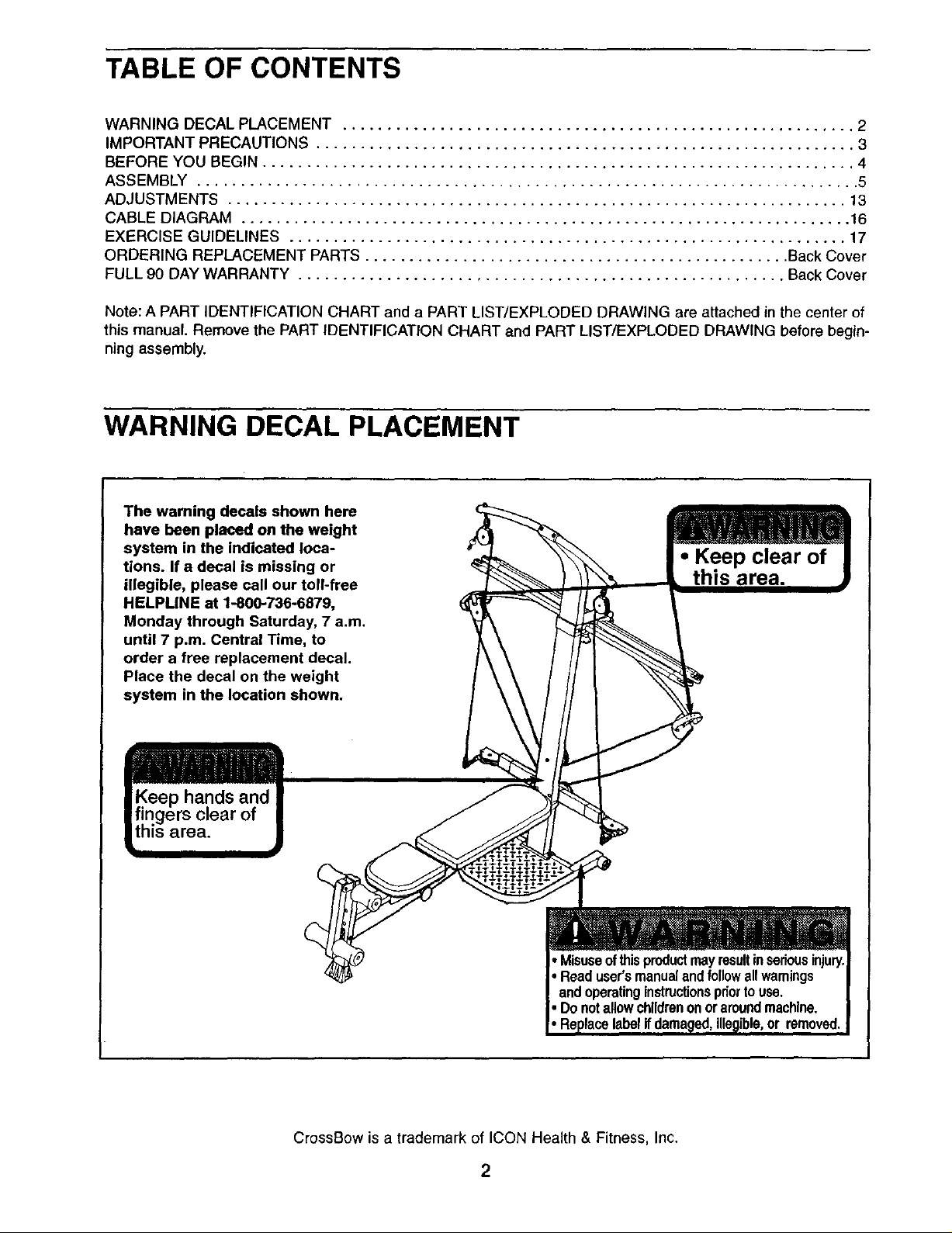
TABLE OF CONTENTS
WARNING DECAL PLACEMENT .......................................................... 2
IMPORTANT PRECAUTIONS ............................................................. 3
BEFORE YOU BEGIN ................................................................... 4
ASSEMBLY ........................................................................... 5
ADJUSTMENTS ...................................................................... 13
CABLE DIAGRAM ..................................................................... 16
EXERCISE GUIDELINES ............................................................... 17
ORDERING REPLACEMENT PARTS ................................................ Back Cover
FULL 90 DAY WARRANTY ....................................................... Back Cover
Note: A PART IDENTIFICATION CHART and a PART LIST/EXPLODED DRAWING are attached Anthe center of
this manual. Remove the PART IDENTIFICATION CHART and PART LIST/EXPLODED DRAWING before begin-
ning assembly.
WARNING DECAL PLACEMENT
The warning decals shown here
have been placed on the weight
system in the indicated loca-
tions. If a decal is missing or
illegible, please call our toll-free
HELPLINE at 1-800-736-6879,
Monday through Saturday, 7 a.m.
until 7 p.m. Central Time, to
order a free replacement decal.
Place the decal on the weight
system in the location shown.
• Keep clear of
]rea.
hands and
_a.
• Misuseofthisproductmayresultinseriousinjury.
• Readuser'smanualandfollowallwamings
andoperatingInstructionspriorto use.
• Donotallowchildrenonoraroundmachine.
removed.
CrossBow is a trademark of ICON Health & Fitness, Inc.
2

IMPORTANT PRECAUTIONS
3
BEFORE YOU BEGIN
Thank you for selecting the innovativeCrossBow TM
weight system. The CrossBow weight system offersa
selection of weight stationsdesigned to develop every
major muscle group of the body, Whether your goal is to
tone your body, build dramatic muscle size and
strength, or improve your cardiovascular system, the
CrossBow weight system wilt help you to achieve the
specific results you want.
For your benefit, read this manual carefully before
using the weight system. If you have additionalques-
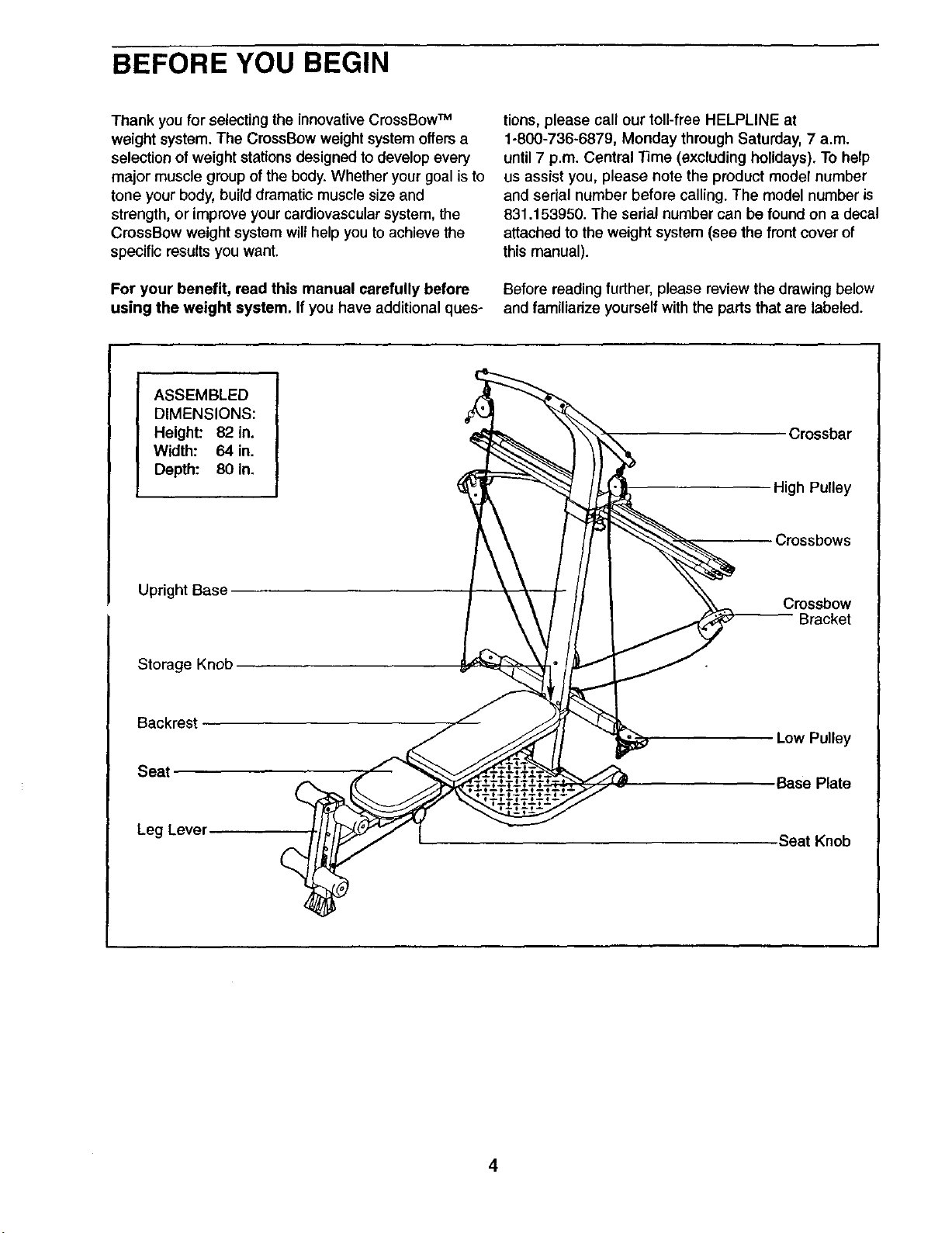
ASSEMBLED
DIMENSIONS:
Height: 82 in.
Width: 64 in.
Depth: 80 in.
tions, please call our toll-free HELPLINE at
1-800-736-6879, Monday through Saturday, 7 a.m.
until7 p.m. Central Time (excluding holidays). To help
us assist you, please note the product model number
and serial number before calling. The model number is
831.153950. The serial number can be found on a decal
attached to the weight system (see the front cover of
this manual).
Before reading further, please review the drawing below
and famUiarize yourself with the parts that are labeled.
Crossbar
High Pulley
Crossbows
Upright Base
Storage Knob
Backrest
Seat
Leg Lever
Crossbow
Bracket
Low Pulley
•Base Plate
Seat Knob
4
ASSEMBLY
• As you assemble the weight system, make sure
all parts are oriented as shown in the drawings.
• For help identifying small parts, use the PART
IDENTIFICATION CHART in the center of this
manual
An | Allen wrench and the following tools (not
included) are required for assembly:
• Two adjustable wrenches
Before beginning assembly, carefully read the
following information and instructions:
• Assembly requires two persons.
• Place all parts in a cleared area and remove the
packing materials. Do not dispose of the packing
materials until assembly is completed.
• Tighten all parts as you assemble them, unless
instructedto do otherwise.
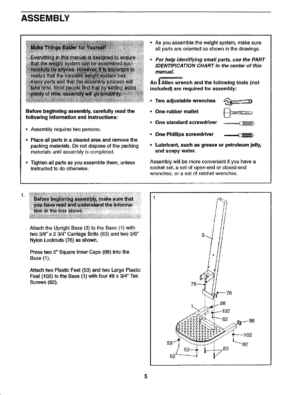
1.
Attach the Upright Base (3) to the Base (1) with
two 3/8" x 2 3/4" Carriage Bolts (83) and two 3/8"
Nylon Locknuts (76) as shown.
Press two 2" Square Inner Caps (98) into the
Base (1).
• One rubber mallet
• One standard screwdriver
• One Phillips screwdriver
• Lubricant, such as grease or petroleum jelly,
and soapy water.
Assembly will be more convenient if you have a
socket set, a set of open-end or closed-end
wrenches, or a set of ratchet wrenches.
/
3-_.
Attach two Plastic Feet (53) and two Large Plastic
Feet (102) to the Base (1) with four #8 x 3/4" Tek
Screws (62).
i
i
1\
i
5
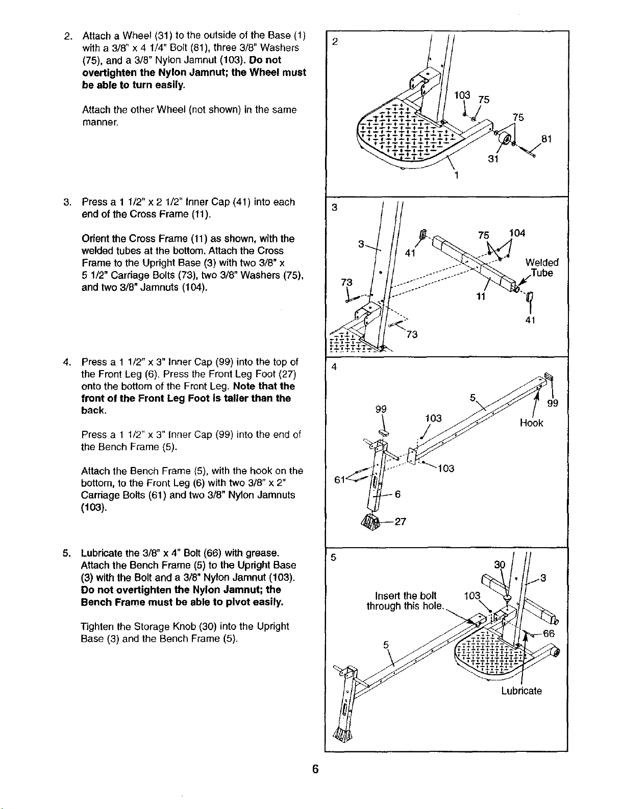
Attach a Wheel (31) to the outside of the Base (1)
2. 2
with a 3/8" x 4 1/4" Bolt (81), three 3/8" Washers
(75), and a 3/8" Nylon Jamnut (103). Do not
overtighten the Nylon Jamnut; the Wheel must
be able to turn easily,
Attach the other Wheel (not shown) in the same
manner.
,
Press a 1 1/2" x 2 1/2" Inner Cap (41) into each
end of the Cross Frame (11).
Orient the Cross Frame (11) as shown, with the
welded tubes at the bottom. Attach the Cross
Frame to the Upright Base (3) with two 3/8" x
5 1/2" Carriage Bolts (73), two 3/8" Washers (75),
and two 3/8" Jamnuts (104).
75
75
81
31 "_
1
3
104
75
Welded
11
41
73
4,
Press a 1 1/2" x 3" Inner Cap (99) into the top of
the Front Leg (6). Press the Front Leg Foot (27)
onto the bottom of the Front Leg. Note that the
front of the Front Leg Foot is taller than the
back,
Press a 1 1/2" x 3" Inner Cap (99) into the end of
the Bench Frame (5).
Attach the Bench Frame (5), with the hook on the
bottom, to the Front Leg (6) with two 3/8" x 2"
Carriage Bolts (61) and two 3/8" Nylon Jamnuts
(103).
8,
Lubricate the 3/8" x 4" Bolt (66) with grease.
Attach the Bench Frame (5) to the Upright Base
(3) with the Bolt and a 3/8" Nylon Jamnut (103).
Do not overtighten the Nylon Jamnut; the
Bench Frame must be able to pivot easily.
Tighten the Storage Knob (30) into the Upright
Base (3) and the Bench Frame (5).
4
5
99
103
103
_y-- 27
Insert the bolt 103
through this hole.
5
Hook
3O
Lubricate
6
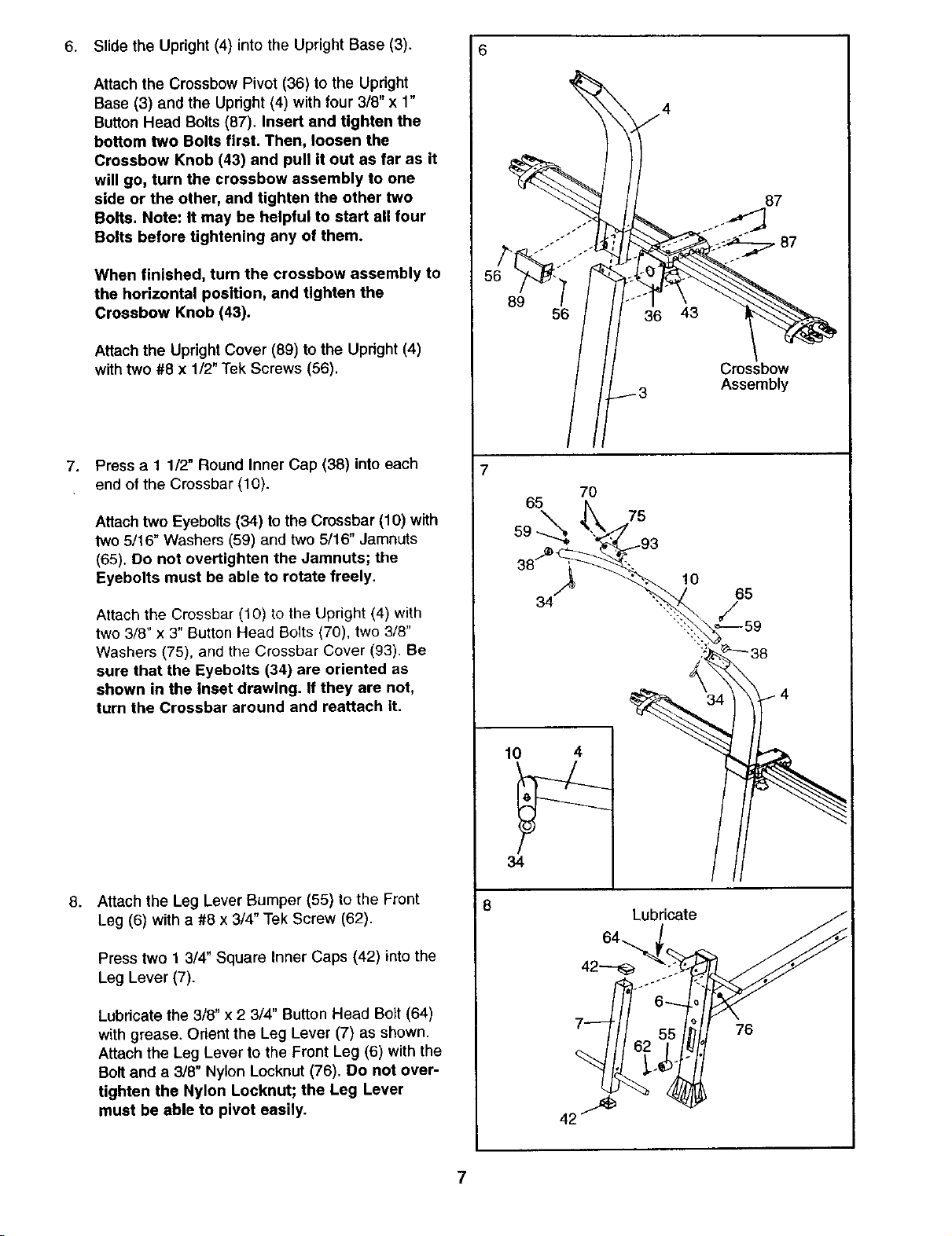
6. Slide the Upright (4) into the Upright Base (3).
Attach the Crossbow Pivot (36) to the Upright
Base (3) and the Upright (4) with four 3/8" x 1"
Button Head Bolts (87). Insert and tighten the
bottom two Bolts first. Then, loosen the
Crossbow Knob (43) and pull it out as far as it
will go, turn the crossbow assembly to one
side or the other, and tighten the other two
Bolts. Note: It may be helpful to start all four
Bolts before tightening any of them.
When finished, turn the crossbow assembly to
the horizontal position, and tighten the
Crossbow Knob (43).
Attach the Upright Cover (89) to the Upright (4)
with two #8 x 1/2"Tek Screws (56).
7.
Press a 1 1/2" Round Inner Cap (38) into each
end of the Crossbar (10).
6
%
_f
.J
87
56
Crossbow
3 Assembly
Attach two Eyebolts (34) to the Crossbar (10) with
two 5/16" Washers (59) and two 5/16" Jamnuts
(65). De not overtighten the Jamnuts; the
Eyebolta must be able to rotate freely.
Attach the Crossbar (10) to the Upright (4) with
two 3/8" x 3" Button Head Bolts (70), two 3/8"
Washers (75), and the Crossbar Cover (93). Be
sure that the Eyebolts (34) are oriented as
shown in the inset drawing. If they are not,
turn the Crossbar around and reattach it.
8.
Attach the Leg Lever Bumper (55) to the Front
Leg (6) with a #8 x 3/4" Tek Screw (62).
Press two 1 3/4" Square Inner Caps (42) into the
Leg Lever (7).
8
Lubricate the 3/8" x 2 3/4" Button Head Bolt (64)
with grease. Orient the Leg Lever (7) as shown.
Attach the Leg Lever to the Front Leg (6) with the
Bolt and a 318" Nylon Locknut (76). Do not over-
tighten the Nylon Locknut; the Leg Lever
must be able to pivot easily.
76
7
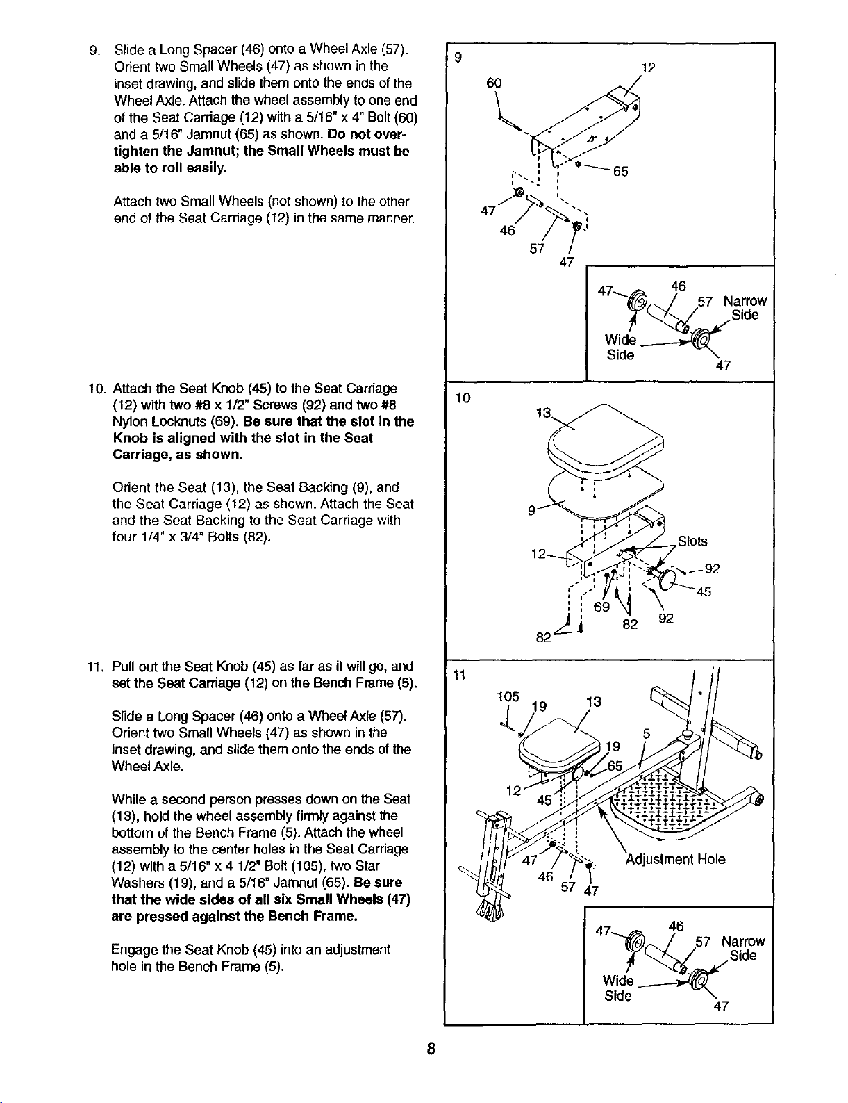
9.
Slide a Long Spacer (46) onto a Wheel Axle (57).
Orient two Small Wheels (47) as shown in the
inset drawing, and slide them onto the ends of the
Wheel Axle. Attach the wheel assembly to one end
of the Seat Carriage (12) with a 5/16" x 4" Bolt (60)
and a 5/16" Jamnut (65) as shown. Do not over-
tighten the Jamnut; the Small Wheels must be
able to roll easily.
Attach two Small Wheels (not shown) to the other
end of the Seat Carriage (12) in the same manner.
9
6O
57
47
47 46
""_._. /' 57 Narrow
L.b_.._/ Side
47
10. Attach the Seat Knob (45) to the Seat Carriage
(12) with two #8 x 1/2" Screws (92) and two #8
Nylon Locknuts (69). Be sure that the slot in the
Knob is aligned with the slot in the Seat
Carriage, as shown.
Orient the Seat (13), the Seat Backing (9), and
the Seat Carriage (12) as shown. Attach the Seat
and the Seat Backing to the Seat Cardage with
four 1/4" x 3/4" Bolts (82).
11. Pull out the Seat Knob (45) as far as it will go, and
set the Seat Carriage (12) on the Bench Frame (5).
Slide a Long Spacer (46) onto a Wheel Axle (57).
Orient two Small Wheels (47) as shown in the
inset drawing, and slide them onto the ends of the
Wheel Axle.
10
Slots
11
105 19 13
While a second person presses down on the Seat
(13), hold the wheel assembly firmly against the
bottom of the Bench Frame (5). Attach the wheel
assembly to the center holes in the Seat Carriage
(12) with a 5/16" x 4 1/2" Bolt (105), two Star
Washers (19), and a 5/16" Jamnut (65). Be sure
that the wide sides of all six Small Wheels (47)
are pressed against the Bench Frame.
Engage the Seat Knob (45) into an adjustment
hole in the Bench Frame (5).
Adjustment Hole
46
57 47
8
 Loading...