

Page 1

Enterprise Media Receiver
Installation Quick Start Guide
General Information
The Wegener Unity 550 is a digital satellite receiver that will receive signals from both C and Ku band
satellite systems. Additional information may be found on the Wegener web site at: www.wegener.com
Unpacking and Inspection
Unity 550
.
The box containing the unit should include:
the Unity 550 Media Receiver a UL Safety Sheet
this Quick Start Guide a power cord
the Li Shin International Enterprise Corp. inline
power supply / Model: 0218B1260
Carefully unpack the unit and the ac power cord and inspect for obvious signs of physical damage that
might have occurred during shipment. Any damage claims must be reported to the carrier immediately.
Be sure to check the package contents carefully for important documents and materials.
NOTE: Save the original packing materials and shipping containers in case the unit must be returned
for repair. Packing the unit in another container in such a way that the unit is damaged will void
the warranty.
Environmental Operating Conditions and Physical Specifications
The table below lists the Unity 550 Environmental Limits and Physical Specifications
Item/Limit Specification
Use Indoor
Altitude Up to 2000 meters
Temperature Range
Relative Humidity (max.)
Weight 6.8 pounds or 3.0844 kilograms
Dimensions (H x W x D) 1.75"x 16.5"x 11" or 44.45 mm x 419.1 mm x 279.4 mm
o
10
80% for temperatures up to 31
humidity at 40
C to 40
o
C
o
o
C
C decreasing linearly to 50% relative
Input Power Rating for Unity 550 12VDC 5.0A
Input Power Rating for inline
power supply
www.wegener.com 800072-02B 1
100-240VAC, 50/60Hz, 1.5A
Page 2
QUICK START GUIDE
Location and Mounting
The Unity 550 is sized at 1RU, and may be mounted in a standard 19-inch equipment rack or set up for
desktop operation. In either location, maintain a clean, dry environment for the
Rack Mounting
The
Unity 550 unit should be installed in such a way that a half-inch clearance is allowed on each side
and a quarter-inch on the top to ensure adequate air flow. Ensure that a hazardous condition is not
produced by uneven loading, or by resting any unsupported equipment on a rack-mounted
unit.
Unity 550.
Unity 550
Parts for the
do
not attach the rubber feet as they interfere with the rack mounting.
Unity 550 unit include 2 angle rack mount brackets and 4 rubber feet. For rack mounting,
1. Remove the 2 screws from the left and right sides of the unit.
2. Insert the angle brackets into the left and right sides of the unit ensuring that the screw holes for
the unit and brackets are aligned.
3. Secure the brackets by re-inserting the screws through the brackets and unit.
4. Install the unit onto the rack.
NOTE: The front brackets must be secured to the rack. If the front brackets are left unsecured, the unit
may shift forward and fall from the rack, and may result in personal injury and/or damage to the
equipment. The internal temperature of the rack should not exceed 40
o
C.
Desktop Installation
Parts for the
installation, do
Unity 550 unit include 2 angle rack mount brackets and 4 rubber feet. For desktop
not attach the brackets.
1. Attach the 4 rubber feet onto the indented areas at the bottom of the unit.
2. Place the unit on a flat surface where it will not be subject to spills or impacts.
3. Route cables to the unit so that they will not be hit or pulled, causing damage to the connectors
or to the unit itself. Ensure a sufficient flow of cool air so that the unit's operating ambient
temperature range is not exceeded.
WARNING: FCC-Mandated Suppression of Radio Frequency Emissions
This is a
Class A product. In a domestic environment this product may cause radio
interference for which the user may need to take mitigating action.
If the Ethernet port has a cable connected to it, that cable must be properly shielded
and grounded to minimize RF emissions that could interfere with nearby equipment.
Circuit Protection and Earthing
When connecting the
Unity 550 unit to the power supply, review the ratings of all equipment in the
circuit to ensure that the branch circuit, as well as the power source, will not be overloaded. Also make
sure that the unit is properly grounded and/or that a protected power strip is used to attach it to the
power supply.
2 800072-02B www.wegener.com
Page 3
Rear Panel Connections
t
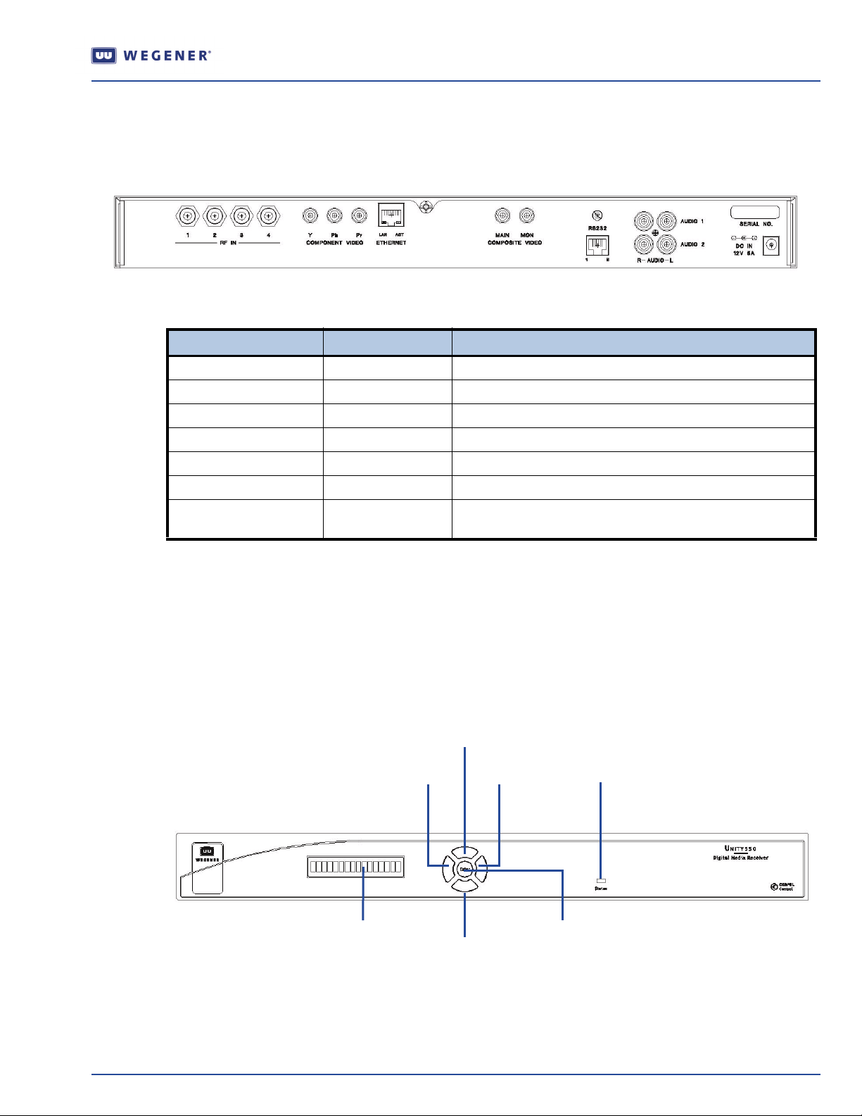
Figure 1 shows the rear panel connections of the Unity 550 that are described in Figure 1.
Signal Connector Description
RF Switch IN - Port 1 F 950 to 2150 MHz signal accepted. LNB power available
RF Switch IN - Port 2, 3, 4 F 950 to 2150 MHz signal accepted. NO LNB power available
Main Video OUT Phono Jack NTSC or PAL, Composite video at 1 Vp-p
Monitor Video OUT Phono Jack NTSC or PAL, Composite video at 1 Vp-p
Audio OUT 1 (R & L) Two Phono Jacks Audio stereo
QUICK START GUIDE
Figure 1: Unity 550 rear panel view
Table 1: Unity 550 Interconnect Descriptions
Audio OUT 2 (R & L) Two Phono Jacks Audio stereo
RS232 Port RJ-12 Serial Asynchronous Data. May be used for terminal, printer, or
CAUTION: Do not connect RJ-12 directly to phone line. Equipment damage may result
Front Panel Connections
Figure 2 show the Unity 550 front panel controls and describes them in Table 2. The IRD can be
controlled via
Display
control methods are supplemental.
COMPEL Network Control, local terminal, modem (remote terminal) and On-Screen-
push buttons. Normally, COMPEL is the primary method of controlling the IRD, while the other
modem (to remote terminal)
Figure 2: Unity 550 Front Panel
left arrow
button
op arrow
button
right arrow
button
LED
LCD
screen
www.wegener.com 800072-02B 3
bottom arrow
button
Enter
button
Page 4
QUICK START GUIDE
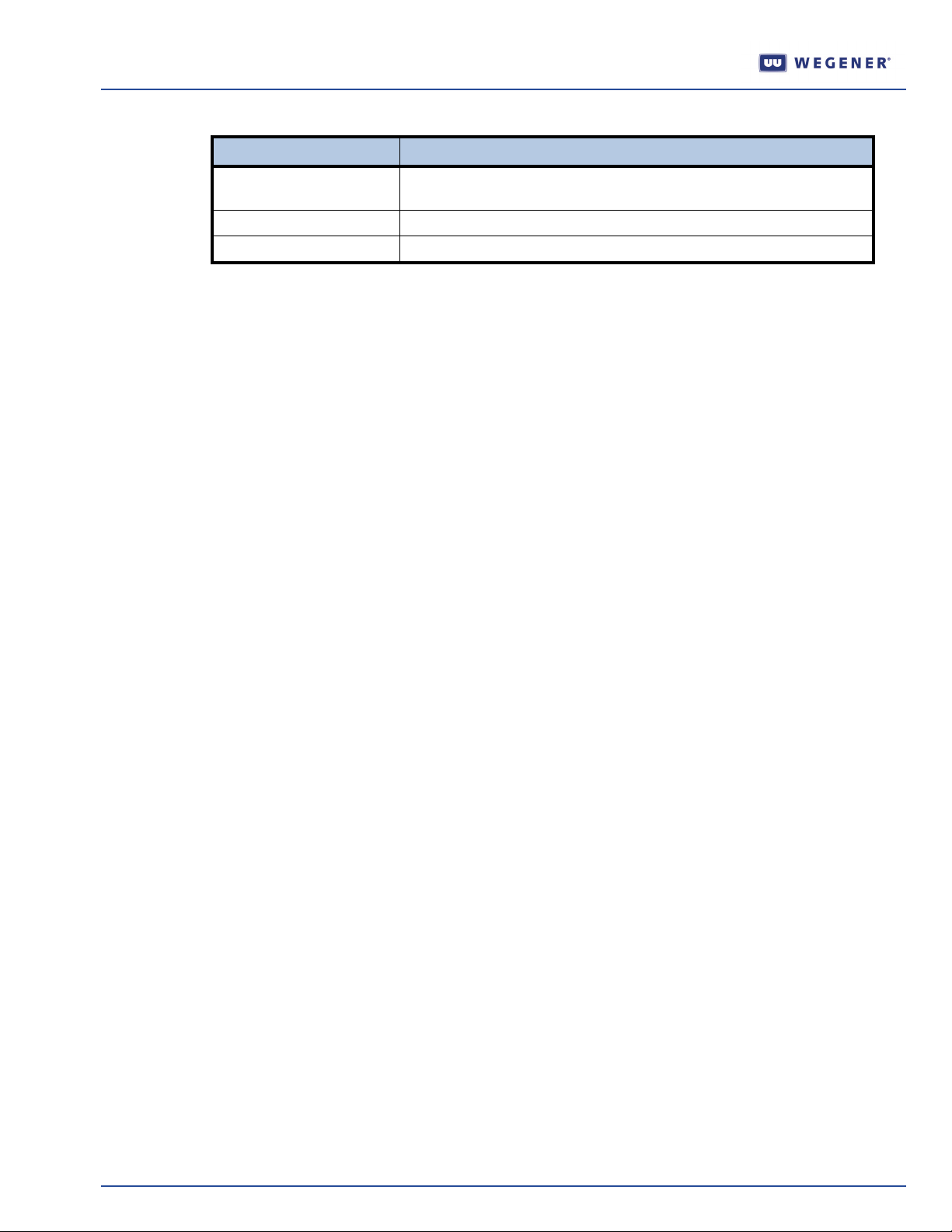
LCD Activates automatically by certain status conditions, such as loss of signal.
Arrow buttons Push buttons activates LCD and selects options displayed.
ENTER Push button enters options selected on LCD.
LCD Menu Navigation
Operate the Unity 550 from the front panel using the arrow buttons and the LCD as shown in Figure 2.
Menu screens on the LCD direct you to screens that control various operating functions including:
programming
audio
Front Panel Functions
Programming Setup
1. Use the right or left arrow buttons to navigate to
2. To edit, press
3. To navigate to
4. To change, press
Table 2: Unity 550 Front Panel Controls
Item Description
To manually activate, press the ENTER button.
Prgm:Prog1.
Enter.
Prog2 or Prog3, use the top and bottom arrow buttons.
Enter.
Audio Setup
Use to setup
Audio 1 or Audio 2 as indicated on the rear of the unit chassis.
1. Use the right or left arrow buttons to navigate to
2. To edit, press Enter.
3. To change, press
Enter.
Closed Captioning (CC) Setup
1. Use the right or left arrow buttons to navigate to
2. To edit, press
3. To navigate to
4. To change, press
Enter.
Sub:CC2 or Sub:CC3 or Sub:CC4, use the top and bottom arrow buttons.
Enter.
Aud:A01 or Aud:A02
Sub:CC1.
4 800072-02B www.wegener.com
Page 5
LED Indications after Power-Up
Within approximately 15 seconds of power up, the IRD gives an indication of stable operation. It
initializes all system components and supplies an operational status. A steady Green LED indicates
that it is locked on a carrier and is capable of producing output (Audio/Video/Data).
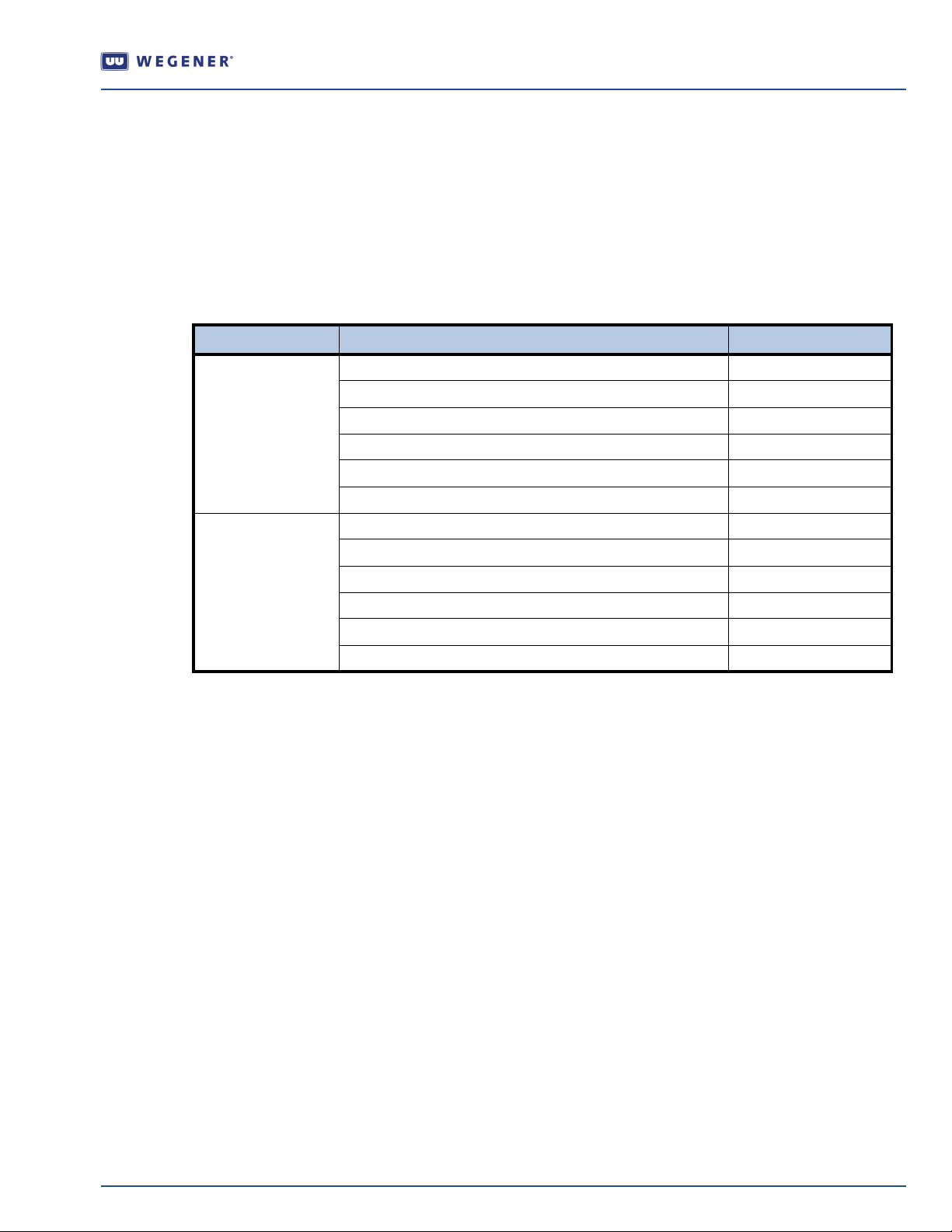
If there is some problem with the IRD or the signal it is receiving the LED flashes Red for alarm
conditions or Amber for warning conditions. In general, alarms indicate that the unit cannot produce
output, while Warnings indicate that, although output is being produced, there is a problem that could
require attention. The most common conditions that produce alarms or warnings are listed in
Table 3: Unity 550 Front Panel Status LED Alarm and Warning Indications
Mode Condition Status LED
Alarm Installation Mode Red Blink = 3
Carrier Table Search Red Blink = 4
Header Search Mode Red Blink = 5
Eb/NO Alarm Red Blink = 7
Not Authorized Red Blink = 11
Alarm Selected Program not available Red Blink = 12
QUICK START GUIDE
Table 3.
Warning Selected Audio not available at Port 1 Amber Blink = 1
OSD (On-Screen Display)
Although the Unity 550 is set up at the factory, you can customize its settings to fit your system using
the
OSD and front-panel buttons. You may also view the existing settings and the various status and
version fields by using the push buttons to navigate through the menus displayed on an attached
monitor.
The
OSD menus allow you to set up or change settings for these functions:
Carrier Status,
Carrier Select
Software Version information
Signal Strength Monitoring,
Serial Port device selection,
Audio Settings
Data PID settings
Marginal Eb/NO Amber Blink = 2
COMPEL Required but No COMPEL in the last 2 minutes Amber Blink = 3
Selected Audio not available at Port 2 Amber Blink = 4
RF Level Low Amber Blink = 5
RF Level High Amber Blink = 6
OSD Setup
The
OSD information is contained in a 14-line x 40-character display in the video output from the
Unity 550 receiver. View the OSD from a monitor connected to the video monitor output of the Unity 550
receiver.
1. From the front panel, use the right or left arrow buttons to navigate to
2. To display the
NOTE: To exit the OSD, select EXIT from the Main Menu on the monitor. When a menu is first shown,
OSD on the monitor, press Enter.
OSD.
the cursor is always placed on its first field.
www.wegener.com 800072-02B 5
Page 6
QUICK START GUIDE
OSD Menus
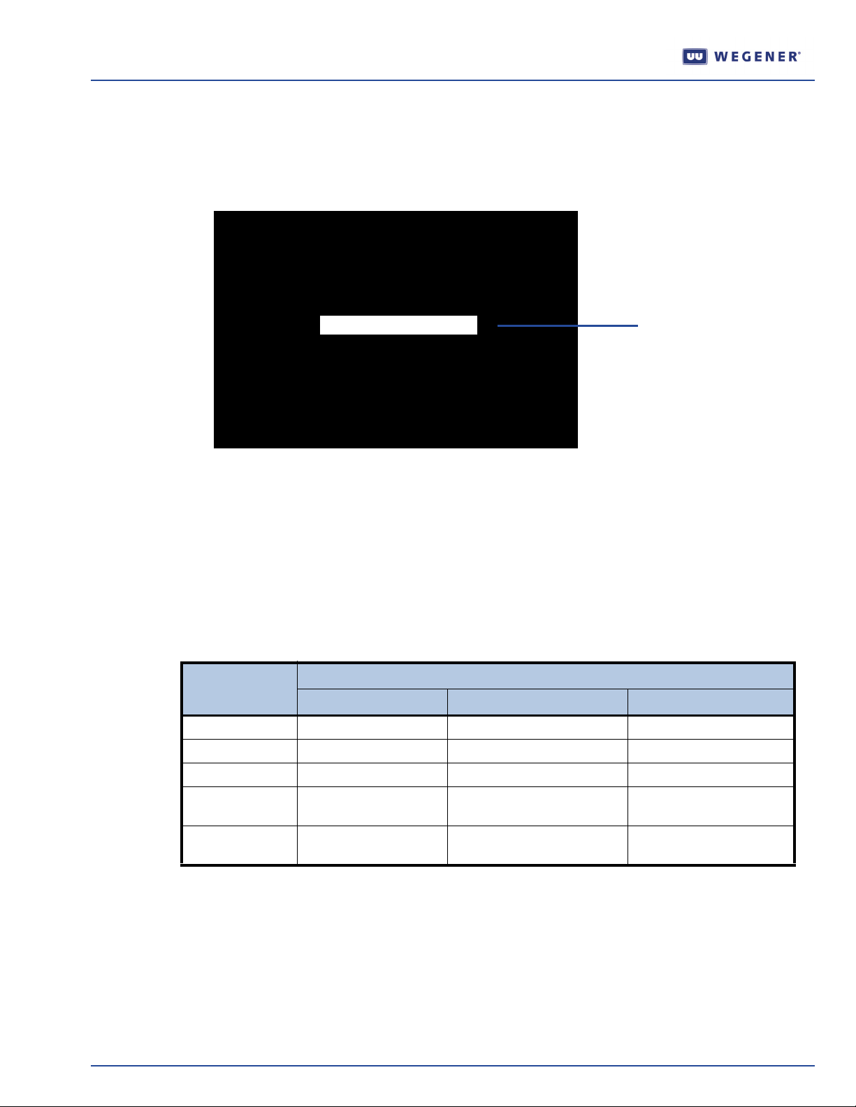
All menus are white text with a solid black background. Highlighted items display as black text on a
white background.
Figure 3 is a representation of the OSD Main Menu.
Figure 3: OSD Main Menu
MAIN MENU
Carrier Status
Carrier Select
Software Version/ Serial No.
Signal Strength
Signal Strength
Serial Port Select
Audio 1 Settings
Audio 2 Settings
Data PID Settings
Exit
Highlighted text
Navigating OSD Menus
Use the arrow and
OSD menus. Selectable fields allow you to change the whole parameter from pre-determined options.
Editable fields allow you to change each digit of the parameter.
NOTE: Once a field is updated, you must select Activate and Exit on the submenu and then press
Enter to update the value of the field. Before pressing Enter, you may go back to any field and
Enter buttons on the Unity 550’s front panel to navigate and edit the fields on the
correct it prior to acceptance.
Table 4: Unity 550 Types of OSD Action Fields
Button
Enter selects submenu goes to editable field no action
right arrow no action goes to editable field moves cursor to right
left arrow no action no action moves cursor to left
up arrow goes to previous
down arrow goes to next submenu goes to next submenu item decreases value of
Main Menu Submenu Edit Mode
goes to previous submenu
submenu
item
Actions
increases value of
highlighted item
highlighted item
6 800072-02B www.wegener.com
Page 7
Warranty
The following warranty applies to all Wegener Communications products:
All Wegener Communications products are warranted against defective materials and workmanship
for a period of one year after shipment to customer. Wegener Communications' obligation under this
warranty is limited to repairing or, at Wegener Communications' option, replacing parts, subassemblies,
or entire assemblies. Wegener Communications shall not be liable for any special, indirect, or
consequential damages. This warranty does not cover parts or equipment, which have been subject to
misuse, negligence, or accident by the customer during use. All shipping costs for warranty repairs shall
be prepaid by the customer. There are no other warranties, express or implied, except as stated herein.
Technical Support
In the event that the unit fails to perform as described, contact Wegener Communications Customer
Service at:
Corporate Office: Service Department:
WEGENER WEGENER
QUICK START GUIDE
11350 Technology Circle Customer Service
John's Creek 359 Curie Drive
Duluth, GA 30097 Alpharetta, GA 30005
www.wegener.com 800072-02B 7
 Loading...