


Installation/Operation Guide
UNITY RF Switch Option
Data, drawings, and other material
contained herein are proprietary to
Wegener Communications, Inc., and
may not be reproduced or duplicated in
any form without the prior permission
of Wegener Communications, Inc.
When ordering parts from Wegener
Communications, Inc., be sure to include
the equipment model number, equipment
serial number, and a description of the part.
In all correspondence with Wegener
Communications, Inc., regarding this
publication, please refer to Manual Number
800016-13 A.
First Edition: August 2000
WEGENER
COMMUNICATIONS
TECHNOLOGY PARK/JOHNS CREEK
11350 TECHNOLOGY CIRCLE
DULUTH, GEORGIA 30097-1502
(770) 814-4000 FAX (770) 623-0698
R

Page 2
1. INTRODUCTION
The UNITY RF Switch is a software-controlled, four-input, single-output, L-band switch. It
allows network and local control of antenna feed selection as well as other signal parameters.
Please read the entire set of instructions before beginning the installation.
2. RF SWITCH KIT INVENTORY
In addition to these instructions, the RF Switch Kit will consist of one (1) each of the following
items:
• RF Switch mounted in a bracket,
• Ribbon Cable (To connect the Switch to the Receiver Expansion Bus)
• Small Philips Screw, self-tapping (To secure the switch PWB to the chassis bottom)
• F-F coax cable
3. TOOLS REQUIRED
Completion of this installation will require the following tools:
• #1 Philips screwdriver
• #2 Philips screwdriver
4. INSTALLATION
There are two variations of this installation. One is for units that already have a cable from the
RF Switch Expansion Bus connector to a connector on the Tuner Board. The other is for units
without this cable. The Expansion Bus may also be labeled as the Relay Expansion Bus.
If your unit has the Expansion Bus/tuner cable already installed, make sure there is a 3-connector
cable in your kit. If there is not, contact Wegener Communications Customer Service (See rear
cover for numbers.) before continuing this installation.
To install the RF Switch Option Card, follow these steps:
A. PREPARE THE UNIT
1. Note the cables and connections for re-installation.
2. Power down the receiver.
3. Move it to a work area.
4. Remove the top cover. Retain the screws for re-installation.
Note: Use the #2 Philips screwdriver for most screws, but some units have #1 Philips
screws in one or more locations. On the UNITY401R, remove the 4 screws
through each of the mounting brackets in addition to the 2 screws on the rear,
and the #1 Philips screw in the top.
800016-13 Page 2 of 6
B. INSTALL THE RF SWITCH
See Figure 1 (Page 5) and Figure 2 (Page 5) of this guide for views of the module and its
installation.
1. Remove the block-out plate from the Module where the switch is to be installed.
These screws and holes will be used to mount the RF Switch in a later step. Use the
#1 Philips Screwdriver for this.
2. From the inside of the unit, install the RF Switch into position. The “F” Connectors
should protrude through the rear panel
3. Install one (1) self-tapping screw through the RF Switch Printed Wiring Board
(PWB) into the hole in the bottom of the chassis. Leave it loose at this time. Only
one screw will be used in this step, and which hole is used will depend on the module
slot. This self-tapping screw “cuts” its own threads in the standoff hole, and may
require moderate effort to turn it.
4. Line up the two holes in the rear of the RF Switch Bracket with the holes mentioned
in Step # B1. Insert the self-tapping screws retained in Step # B1 through the receiver
rear panel into the RF Switch Bracket. Tighten these screws snugly, but do not
overtighten.
Page 3
5. Tighten the Screw inserted in Step # B3 at this time. Do not overtighten.
6. Connect the supplied 10-pin cable from J1 on the RF Switch PWB to the appropriate
connector on the receiver motherboard. If there is a cable from the RF Switch
Expansion Bus to another board (either the Tuner Board or a Relay Board), note its
location and remove that cable. Connect the middle connector of the new cable to the
same connector on the previously installed Board.
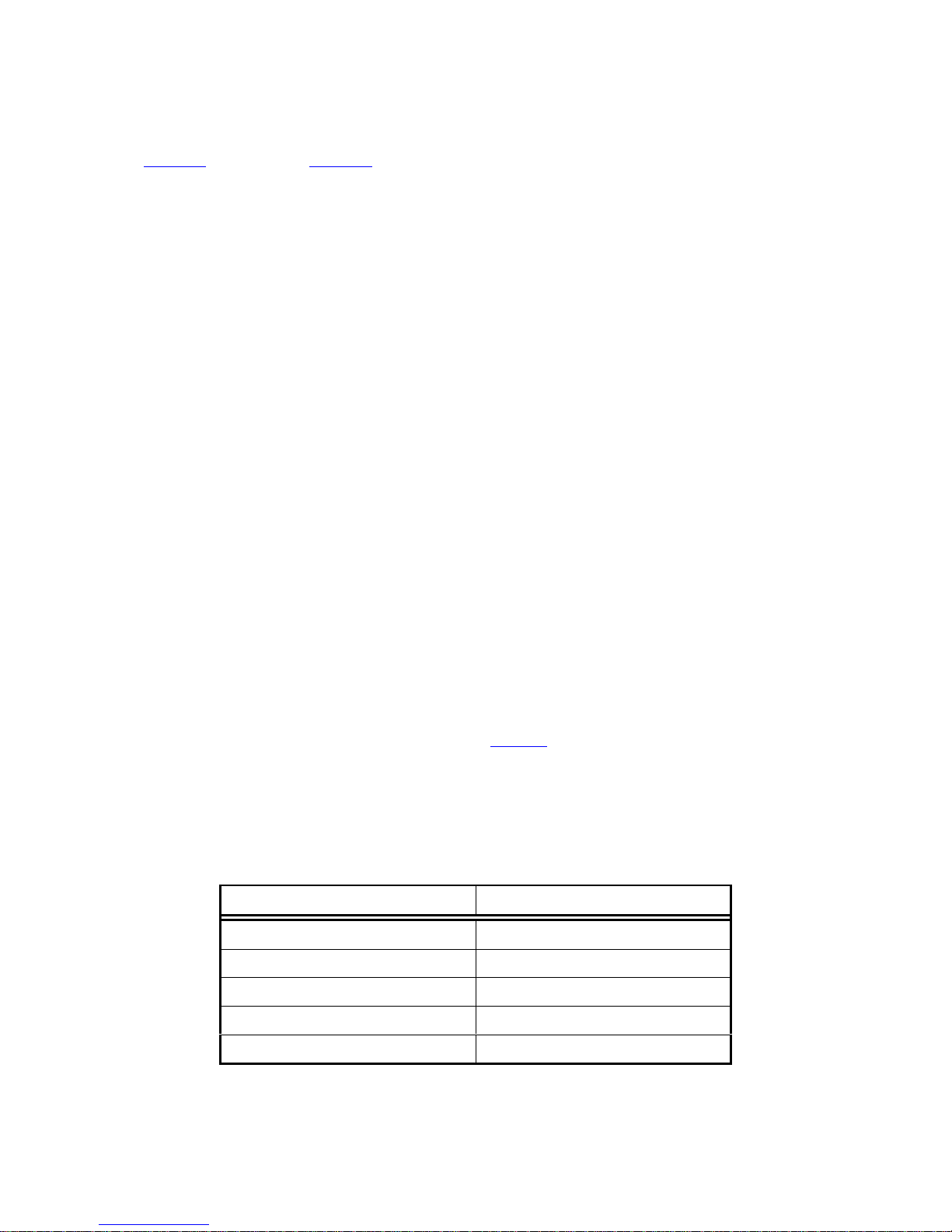
7. On most units, the motherboard connector will be labeled “RF Switch Expansion
Bus” or “Relay Expansion Bus,” and should have a number beside it corresponding to
the number in the following table. See Table 1, below, for the various models. Make
sure Pin 1 (the Red Line) on each cable connector goes to Pin 1 on each board
connector. If you have any questions about this, contact system network control or
Wegener Customer Service at 770-814-4057. Additional numbers are shown on the
rear cover of this installation guide.
Table 1. Receiver Models and RF Switch Expansion Bus Connector Numbers
Receiver Model Connector Number
UNITY401R J7
UNITY500 J11
UNITY4000 J11
UNITY4422 J16
UNITY5000 J49
Page 3 of 6 800016-13

Page 4
C. SET RF SWITCH OPTIONS
1. Set Jumpers on the option card to the dotted position.
When setting the jumpers, observe that there are three pins on each header. The
jumper covers two of these pins and connects them together electrically. In one
position Pin 2 (center pin) is connected to Pin 1, while in the other position Pin 2 is
connected to Pin 3. Changing the jumpers changes the configuration of the circuit
board and how the board operates.
There is a dot on the board near either pin 1 or pin 3 of each jumper. Setting the
jumper so pin 2 is connected to this pin means the jumper is in the “dotted” position.
This indicates “Normal” operation of Wegener equipment.
All three of the jumpers on the RF Switch PWB should be in the “Dotted”
position.
D. RE-INSTALLING THE UNIT
1. Replace the cover and re-install the screws holding it in place. As with the RF
Switch, tighten the screws but do not overtighten.
2. Connect the “Output” connector of the RF Switch with the “RF Input” connector of
the receiver it is installed in with the supplied F-F coax cable. Tighten the Fconnector “finger tight.” See the Caution below.
3. Install the unit into the equipment rack, following the cautions and instructions in its
user manual. Re-install the cables as they were when the unit was removed from the
rack, with the exception in Step # D2.
4. Connect the desired RF inputs to the “F” connectors on the RF Switch. Again,
observe the caution regarding the force required to tighten these connectors.
Normally, the RF Inputs are configured according to instructions from the Network
Control, or Uplink. They will need to know which input is connected to which
connector so they can intelligently control program content.
* * * WARNING * * *
When connecting cables to “F” type connectors apply a force of no more than 12 inch lb.
(Finger tight). Avoid connecting adapters directly to “F” type connectors. Use at minimum
a 1-foot flexible extension cable between “F” type connectors and adapters.
E. OPERATION
To set up and operate a receiver with the RF Switch installed, consult the owner’s manual
for that unit. See the “Terminal Commands” or “On Screen Display” section for setup
and control.
800016-13 Page 4 of 6

Rear
UNITY4000
MOTHER
BOARD
P/S
Cable from RF Switch
RF Switch
Expansion
Out to Tuner In
1
Tuner
Tuner Board
Module 1
Hole Used
If Mounted
In Module 1
J1
Red Line
RF Signal In x 4
0
2
1
1
J
1
Page 5
screws from
blockout plate
Mounting
Bracket
Hole used if
Mounted in
Module 2
STANDOFFS
3 in each
Module area
Figure 1. Typical Two-Connector-Cable Installation
Rear
UNITY4000
MOTHER
BOARD
P/S
Cable from RF Switch
Red Line
RF Switch
Expansion
Front
Out to Tuner In
1
Tuner Board
1
Tuner
RF Signal In x 4
Module 1
Hole Used
If Mounted
In Module 1
J1
Tuner Board
Connector
screws from
blockout plate
Mounting
Bracket
10
2
J1
1
Hole used if
Mounted in
Module 2
STANDOFFS
3 in each
Module area
Figure 2. Typical Three-Connector-Cable Installation
Front
Page 5 of 6 800016-13

Page 6
SERVICE RETURN ADDRESS
Service Department RMA# ________
Wegener Communications, Inc.
359 Curie Drive
Alpharetta, GA 30005
SERVICE CONTACT NUMBERS AND ADDRESSES
Voice: (770) 814-4057
FAX: (678) 624-0294
email: service@wegener.com
800016-13 Page 6 of 6
 Loading...