


UNITY500 - Installation Quick Start Guide
The UNITY500 is a digital satellite receiver that will receive signals from both C and Ku band satellite systems.
Your box should include:
1. The UNITY500 Satellite Receiver
2. This one-page installation guide
3. UL Safety Sheet
4. Power cord
A full user manual is available on-line.
For more information and detailed instructions, visit http://www.wegener.com.
Rear Panel Connections
The UNITY500 rear panel connections are shown and described below.
UNITY500 Rear Panel
RISQUE DE CHOC ELECTRIQUE NE PAS OUVRIR
MODULE
RF IN
RS232
1 6
AUDIO
R L
VIDEO
MAIN
OUTOUT OUT
OUT
MONITOR
AVIS:
RISK OF ELECTRIC SHOCK
DO NOT OPEN
123456
S/N
UNITY500 Rear Panel With Smart Card Slot And Ethernet Connector
115/230VAC
0.8/0.5A
50/60Hz
RISQUE DE CHOC ELECTRIQUE NE PAS OUVRIR
MODULE
RF IN
RS232
1 6
AUDIO
R L
VIDEO
MAIN
OUTOUT OUT
OUT
10/100
MONITOR
BASE T
1 8
SMART CARD
AVIS:
RISK OF ELECTRIC SHOCK
DO NOT OPEN
123456
S/N
115/230VAC
0.8/0.5A
50/60Hz
UNITY500 Interconnections
SIGNAL CONNECTOR DESCRIPTION
RF IN F 950 to 2150 MHz signal accepted. LNB power available.
RF SWITCH IN
(Optional)
RF SWITCH OUT F 1-of-4 RF inputs selected, Connects to RF IN.
MAIN VIDEO OUT RCA Phono Jack NTSC or PAL, Composite video at 1Vp-p into 75 ohm Load
MONITO-VIDEO OUT RCA Phono Jack NTSC or PAL, Composite video at 1Vp-p into 75 ohm Load
AUDIO OUT (R & L) Two RCA Phono
RS232 PORT RJ-12 Serial Asynchronous Data. May be used for terminal, printer, or modem
F (4 Inputs) 950 to 2150 MHz signal accepted. NO LNB power available.
Stereo Audio, ~6.18 vp-p into 10k ohm Load
jacks
(to remote terminal).
* * * CAUTION * * *
DO NOT CONNECT RJ-12 DIRECTLY TO PHONE LINE.
EQUIPMENT DAMAGE MAY RESULT.
800010 Rev. A – Printed in USA
Page 1 of 4
* * * WARNING * * *
This is a Class A product. In a domestic environment this product may cause radio
interference in which case the user may be required to take adequate measures.
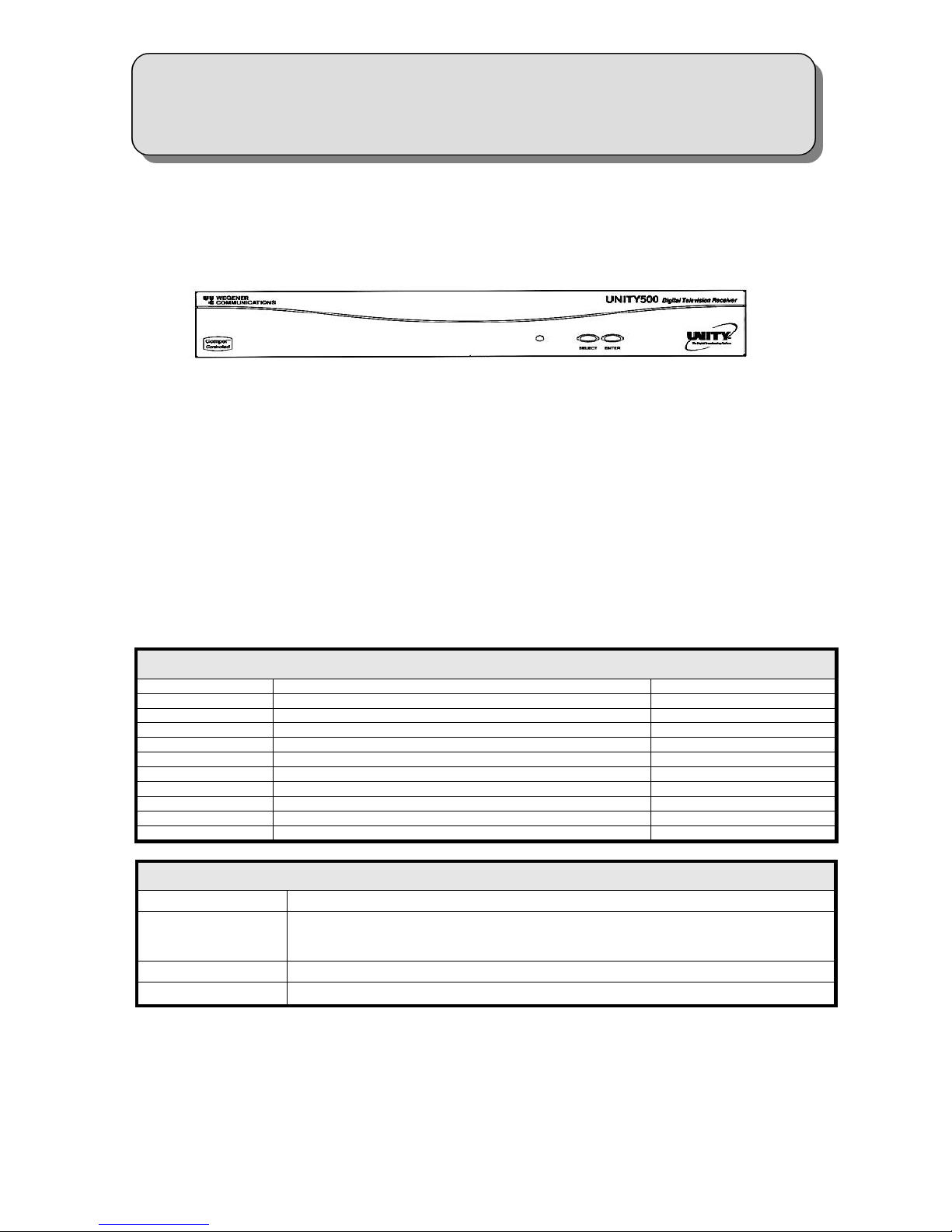
Front Panel Controls and Indicators
The UNITY500 front panel indicators and controls are shown and described below.
UNITY500 Front Panel
GENERAL
The IRD can be controlled via COMPEL Network Control, local terminal, modem (remote terminal) and OnScreen-Display push buttons. Normally, COMPEL is the primary method of controlling the IRD, while the other
control methods are supplemental.
LED INDICATION AFTER POWER-UP
Within approximately 15 seconds of power up, the IRD should give an indication of stable operation (it has
initialized all system components and is supplying an operational status). A steady green LED indicates that it is
locked on a carrier and is capable of producing output. (Audio/video/data)
If there is some problem with the IRD or the signal it is receiving the LED will begin flashing red for alarm
conditions or amber for warning conditions. In general alarms are an indication that it cannot produce output
and warnings will allow the production of output, but there is a problem that could require attention. Some of
the more common conditions, which can produce alarms or warnings, may be found in the following table:
LED Indications
MODE CONDITION STATUS LED
ALARM Installation Mode Red Blink = 3
Carrier Table Search Red Blink = 4
Header Search Mode Red Blink = 5
Eb/NO Alarm Red Blink = 7
Not Authorized Red Blink = 11
WARNING Marginal Eb/NO Amber Blink = 2
COMPEL Required but No COMPEL in the last 2 minutes Amber Blink = 3
Selected Audio not available Amber Blink = 4
RF Level Low Amber Blink = 5
RF Level High Amber Blink = 6
UNITY500 Front Panel Controls and Indicator
ITEM DESCRIPTION
On-Screen- Display
<SELECT> Push button activates (OSD) and selects options displayed.
<ENTER> Push button enters options selected on OSD.
On-Screen-Display (OSD) of IRD may be activated by pressing the <SELECT> front panel
push-button switch. It is also automatically activated by certain IRD status conditions such as
loss of signal.
800010 Rev. A – Printed in USA
Page 2 of 4

ON-SCREEN DISPLAY (OSD)
The OSD information is contained in a 14-line x 40-character display in the video output from the receiver. This
output is viewed on a monitor connected to the video monitor output of the receiver. Turn it on by pressing
either the SELECT or ENTER push-button on the front panel. Remove the display by selecting EXIT from the
Main Menu. When a menu is first shown, the cursor is always placed on its first action field (or action-with-edit
field, whichever is first).
The OSD provides the following: 1. Carrier Status, 2. Signal Strength Monitoring, 3. Serial Port device
selection, 4. Software Version, and 5. The ability to make changes to unit settings.
All menus are white text with a solid blue background. When highlighted, they show as blue text on white
background. The cursor can be moved only to the fields listed below. The function of each push button for each
field type is described below.
OSD Fields
FIELD SELECT ENTER
Action Field
Action w/ Edit Field
Edit Field
Edit Field w/ Choices
Moves cursor to next action field (or action w/ edit field,
which ever is next). Wraps at end.
Same as for action field. Moves cursor to
If cursor is not on last digit within edit field, moves cursor to
next digit. Else, moves to next action field (or action w/ edit
field, which ever is next)
Moves cursor to next action field (or action w/ edit field,
which ever is next).
Takes action on the current
field.
corresponding edit field.
Increments current digit within
edit field. Wraps back to
beginning after 9.
Scrolls through list of choices.
Wraps back to beginning after
last.
CUSTOMIZING AND VIEWING SETTINGS FOR YOUR SYSTEM
Though the UNITY500 is set up at the factory, you can customize its settings to fit your system using the OSD
and front-panel push buttons. You may also view those settings and various status and version fields from the
front panel, viewing on a monitor.
Environmental Operating Conditions & Physical Specifications
Use Indoor
Altitude Up to 2000 meters
Temperature Range 10 o C to 40 o C
Relative Humidity (max.)
Weight 10.6 pounds or 4.81 kilograms
Dimensions (H x W x D) 3.5”x 19”x 10.5” or 88.9 mm x 482.6 mm x 266.7 mm
Input Power Rating 90-132Vac & 175-264Vac, 43 Watt, 50/60 Hz
Elevated Operating Ambient
If equipment is installed in a closed or multi-unit rack assembly, the operating ambient of the rack may be
greater than the room ambient. Therefore, considerations should be given to the TMRA, or Temperature inside
the Mounting Rack, and not just inside the room.
Reduced Air Flow
Installation of the equipment in a rack should be such that the amount of airflow required for safe operation of
the equipment is not compromised.
Mechanical Loading
Mounting of equipment in a rack should be such that a hazardous condition is not achieved due to uneven
loading. This unit is not very heavy, but total rack loading should be considered.
80% for temperatures up to 31o C decreasing linearly to 50% relative
humidity as 40o C.
Circuit Overloading
Consideration should be given to the connection of the equipment to the supply circuit and the effect that
overloading of circuits could have on over-current protection and supply wiring. Appropriate consideration of
equipment nameplate ratings should be used when addressing this concern.
Reliable Earthing
Reliable earthing of rack-mounted equipment should be maintained. Particular attention should be given to
supply connections other than direct connection to the Branch (use of power strips).
800010 Rev. A – Printed in USA
Page 3 of 4

Desktop Installation
To set up the UNITY500 in a desktop environment, place it on a flat surface where it will not be subject to being
hit or pushed, and will not have anything spilled or dropped on it. Also, the cables connected to the unit should
be routed so they are not hit or pulled, which might cause damage to the connectors or to the unit itself.
Additionally, there should be sufficient flow of cool air so the unit stays within its operating parameters.
Rack Installation
When installed in an equipment rack, it is best that the UNITY500 be supported by angle brackets or cross
supports. These should be screwed or bolted securely to the equipment rack, and be capable of supporting the
unit and its connecting cables. Do NOT install the unit if you have doubts about the unit being safely supported.
There are also 4 holes in the front brackets, which are designed to accept screws for further anchoring. It is
also essential that these brackets be used so the unit cannot be moved forward and fall from the rack. It is
always best to install the angle brackets or cross-members before setting the unit in place. Then, prior to
installing cables, put anchored screws or bolts-and-nuts into place on the front brackets. Failure to do this can
lead to pushing the unit out the front of the rack in later steps.
Warranty
The following warranty applies to all Wegener Communications products. All Wegener Communications
products are warranted against defective materials and workmanship for a period of one year after shipment to
customer. Wegener Communications' obligation under this warranty is limited to repairing or, at Wegener
Communications' option, replacing parts, subassemblies, or entire assemblies. Wegener Communications shall
not be liable for any special, indirect, or consequential damages. This warranty does not cover parts or
equipment, which have been subject to misuse, negligence, or accident by the customer during use. All
shipping costs for warranty repairs shall be prepaid by the customer. There are no other warranties, express or
implied, except as stated herein.
Technical Support
In the event the unit fails to perform as described, contact Wegener Communications Customer Service at (770)
814-4057, FAX (678) 624-0294, or E-mail “service@wegener.com”.
Corporate Office Service Department
Wegener Communications, Inc. 359 Curie Drive
11350 Technology Circle Alpharetta, GA 30005
Duluth, GA 30097
800010 Rev. A – Printed in USA
Page 4 of 4
 Loading...