

Page 1
800034-02 Rev. A page 4 of 4 Wegener Communications, Inc. 800034-02 Rev. A page 1 of 4 Wegener Communications, Inc.
Indicators
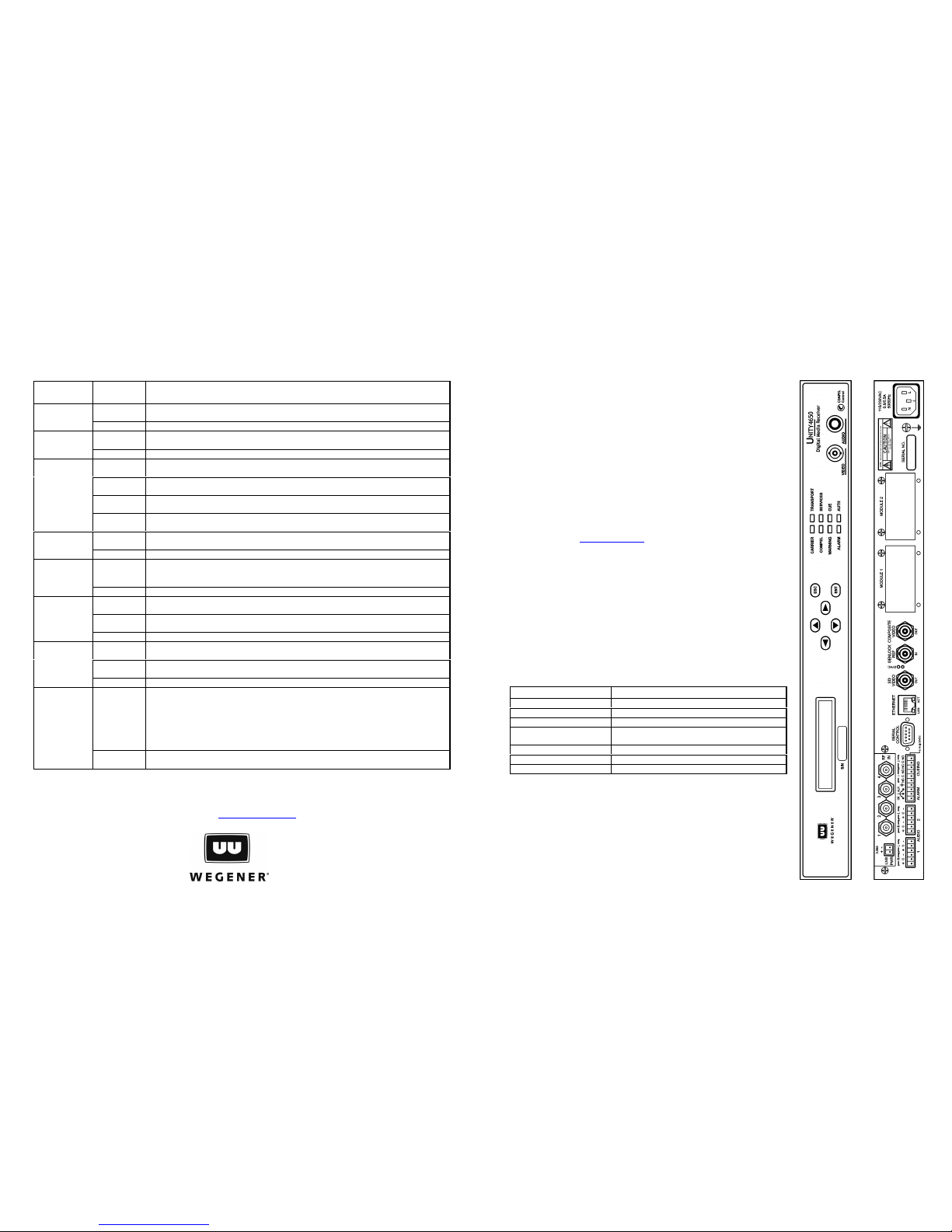
Eight light-emitting diodes (LEDs) provide status information about your U4650 and its processes:
Indicator
Color and
State
Description
GREEN
constant
Unit has demod and FEC lock on the RF carrier
CARRIER
Off Unit does not have demod and FEC lock on the RF carrier
GREEN
constant
Unit recognizes a valid transport stream
TRANSPORT
Off Unit does not recognize a valid transport stream
GREEN
constant
COMPEL control stream received within last two minutes (including keep-alives) while
locked continuously on the current transport stream for >2 minutes
GREEN
flash
Unit has had a verified transport stream for >2 minutes and COMPEL is required but
no valid COMPEL
GREEN
flutter
COMPEL has been addressed to unit within last 5 seconds (excluding keep-alives).
COMPEL
Off
Otherwise. Note that this LED must be OFF when there is no valid Transport stream
OR COMPEL
GREEN
constant
Unit is processing services for delivery.
SERVICES
Off Unit is not processing services.
YELLOW
constant
One or more warning indications present - usually indicates a problem with the
incoming signal, a minor unit fault, a possible impending failure, or that important
information is available
WARNING
Off No warning conditions.
GREEN
constant
A user cue relay is closed (energized).
GREEN
flutter
During a user relay “pulse” activation on any relay.
CUE
Off All user cue relays are open (de-energized).
RED
constant
One or more current alarm indications.
RED blink
An alarm event has occurred in the past and has not been acknowledged and cleared
by the user. Note that the alarm LED may also blink while on.
ALARM
Off No current alarm condition exists.
GREEN
constant
Unit has transport MPEG sync and the stream is not scrambled (in the clear).
Streams that are “clear” are always presumed to be “authorized” -- OR -- Unit is
authorized for current scrambled transport stream (or selected program) and has
transport MPEG sync. When using Wegener CA (’97 Version), being “authorized”
means being addressed with current and valid ciphered keystream messages. In a
PIN system, if the transport stream is scrambled, and the unit has been programmed
with any key other than the null ‘00000’, then it presumes that it is “authorized”.
AUTH
Off
Unit has transport sync, the transport stream is scrambled, and the unit is NOT
authorized. Also OFF if no transport sync.
Technical Support
In the event the unit fails to perform as described, contact Wegener Communications Customer Service by phone at
(770) 814-4057, by FAX at (678) 624-0294, or E-mail [email protected] .
Unity 4650 Digital Media Receiver/Decoder
Quick Start Guide
Introduction
The Wegener Model Unity 4650 Digital Media Receiver/Decoder is a fully DVBcompliant satellite video IRD. If equipped with a receiver card, the U4650 receives
an L-band RF carrier from an external LNB, demodulates the carrier, and then
extracts the MPEG transport stream. If equipped with an ASI transport card, it
decodes the ASI line code and extracts the resulting transport stream. In both
cases, if conditional access has been applied, it then descrambles the transport
stream (or individual programs) if authorized. The U4650 then decompresses a
selected program to provide both analog audio/video outputs as well as (optional)
serial digital video with two pairs of embedded digital audio. All audio/video outputs
may be (optionally) genlocked - supplied synchronized to a station composite video
reference.
This guide provides information for setup and initial operation of the U4650.
Additional information may be found in the User's Manual (p/n 800034-01) on the
Wegener web site at www.wegener.com (click Support and follow the hyperlinks to
access the Unity 4650 Manual).
In addition to this guide, your box should include:
1. Unity 4650 Digital Media Receiver/Decoder
2. Power cord 3. UL safety sheet
Front and Rear Panel Views
The front and rear (typical) panels of the Unity 4650 are shown in the illustration at
right. The Transport Input and Option Module slots may be populated according to
options ordered.
Environmental Conditions & Physical Specifications
Characteristic Specification
Use Indoor
Altitude Up to 2000 meters
Temperature Range 10oC to 50oC
Relative Humidity (max.) 80% for temperatures up to 31oC decreasing
linearly to 50% relative humidity at 40oC.
Weight 10.5 pounds or 4.76 kilograms
Dimensions (H x W x D) 1.75" x 19" x 15"
(44.5 mm x 483 mm x 381 mm)
Input Power Rating 90-132Vac or 175-264Vac, 45 Watt, 50/60 Hz
Warranty
All Wegener Communications products are warranted against defective materials
and workmanship for a period of one year after shipment to customer. Wegener
Communications' obligation under this warranty is limited to repairing or, at
Wegener Communications' option, replacing parts, subassemblies, or entire
assemblies. Wegener Communications shall not be liable for any special, indirect,
or consequential damages. This warranty does not cover parts or equipment,
which have been subject to misuse, negligence, or accident by the customer during
use. All shipping costs for warranty repairs shall be prepaid by the customer.
There
are no other warranties, express or implied, except as stated herein.
Corporate Office
Wegener
11350 Technology Circle
Duluth, GA 30097
Service Department
Wegener
359 Curie Drive
Alpharetta, GA 30005
Page 2
800034-02 Rev. A page 2 of 4 Wegener Communications, Inc. 800034-02 Rev. A page 3 of 4 Wegener Communications, Inc.
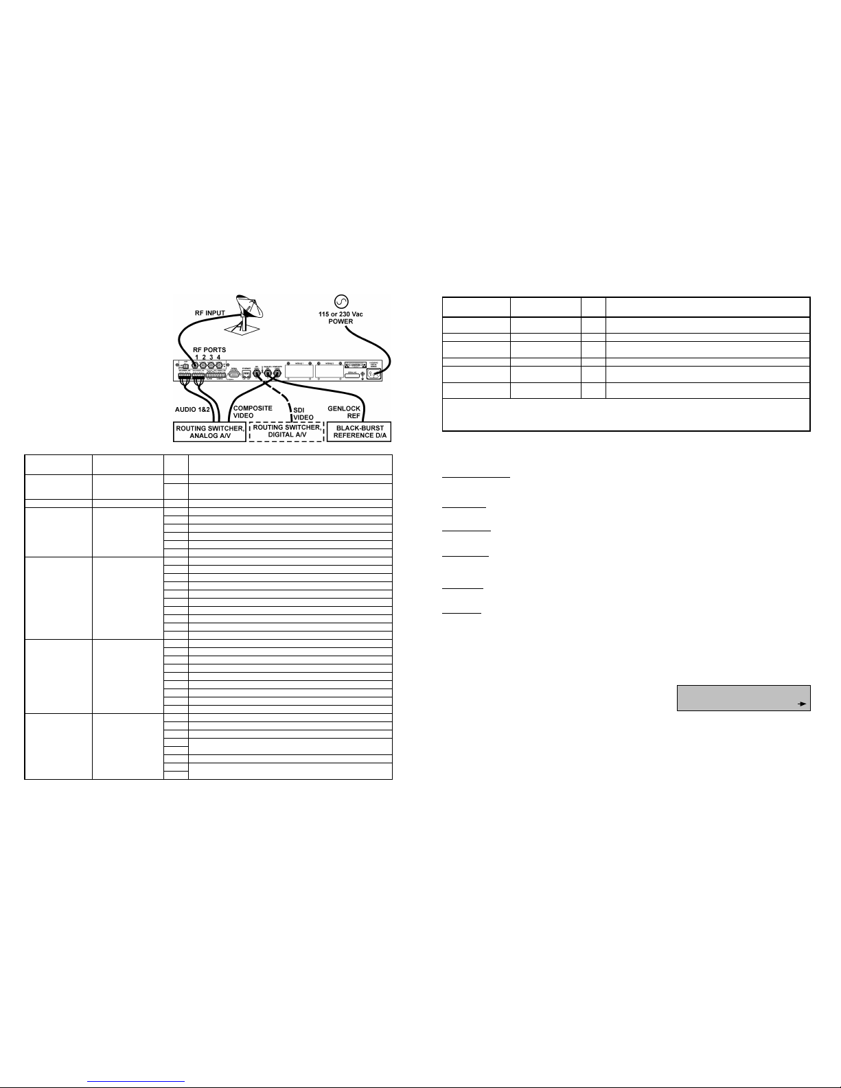
System Setup
The diagram at right illustrates possible
system setups for either analog (solid lines) or
digital (dashed lines) audio/video routing:
Connections
The following table lists connector types, pin
numbers, and signal descriptions for each of
the front- and rear-panel connectors.
Connector
Designation
Type Pin Signal Description
1 LNB DC Output positive leg
LNB PWR *
2-pin male header
(mates to removable
terminal-strip)
2 LNB DC Output return leg
RF IN –1 through 4 Type F coax jacks 4-way RF Switch Inputs
1 Right ‘+’
2 Right GND
3 Right ‘-’
4 Left ‘+’
5 Left GND
AUDIO
(same for both
ports 1 and 2)
6-pin male header
(mates to removable
terminal strip)
6 Left ‘-’
1 OK (COM closes here when OK)
2 COM:
3 Alarm (COM closes here on alarm or if power is off)
4 GND
5 Cue Relay #1: N.C. contact
6 Cue Relay #1: Common contact
7 Cue Relay #1: N.O. contact
8 Cue Relay #2: N.C. contact
9 Cue Relay #2: Common contact
ALARM/ CUEING
10-pin male header
(mates to removable
terminal strip)
10 Cue Relay #2: N.O. contact
1 DCD (internally pulled to +5V)
2 RxD (data output)
3 TxD (data input)
4 DTR (not connected)
5 GND
6 DSR (internally pulled to +5V)
7 RTS (internally pulled to +5V,may be upgraded for handshaking)
8 CTS (not used presently, may be upgraded for handshaking)
SERIAL CONTROL
RS232, 9-pin D
female jacks
9 RI (internally pulled to +5V, with weak current limiting)
1 TXDO +
2 TXDO 3 RXDI +
4
5
Shorted together, then terminated into an AC ground.
6 RXDI 7
ETHERNET RJ45 Jack
8
Shorted together, then terminated into an AC ground.
Connector
Designation
Type Pin Signal Description
SDI VIDEO OUT BNC Jack
Serial 270 Mbaud component Digital Video out with two
embedded AES3 digital audios (optional)
GENLOCK REF IN BNC Jack Genlock Reference external timing input (optional)
COMPOSITE
VIDEO OUT
BNC Jack Composite Video Output
115/230 VAC Std. IEC Receptacle AC line in
Front-panel monitor
option AUDIO **
¼” stereo
phone jack
Stereo audio headphone monitor, selectable between audio
ports 1 or 2
Front-panel monitor
option VIDEO
BNC Jack Composite Video monitor
* Where LNB DC is supplied on RF center pins this header is not included. When four RF inputs are supplied without
this header, LNB DC is supplied on center pin of Port 4. Note that Compel network can lock LNB DC to OFF.
** After plugging in headphones, the unit immediately displays a screen prompting the user to select the Audio Port to
be monitored.
Danger
To avoid damage to this and other equipment, or personal injury, the following items should be strictly observed.
Elevated Operating Ambient
When equipment is installed in a closed or multi-unit rack assembly, the operating ambient of the rack environment may be greater than the room
ambient. Therefore, consideration should be given to the ambient air temperature within the rack, and not just inside the room, when deciding if the
maximum recommended ambient operating temperature (T
MRA
) is being met.
Reduced Air Flow
Equipment should be installed such that airflow required for safe operation of the equipment is not compromised. The U4650 may be arranged in a rack
without empty space between units if heat rise is prevented by ensuring its side vents remain unblocked with adequate clearance around the vent holes.
Mechanical Loading
Mounting of the equipment in a rack should be such that a hazardous condition is not produced by uneven loading. This unit is not very heavy, but total
rack loading must be considered. Also, do not rest any unsupported equipment on your U4650.
Circuit Overloading
Consideration should be given to the connection of the equipment to the supply circuit and the effect that overloading of circuits could have on
overcurrent protection and supply wiring. Ensure that the total rack or breaker power consumption does not exceed the limits of the AC branch circuit.
Appropriate consideration of equipment ratings should be used when addressing this concern.
Reliable Earthing
Reliable earthing of rack-mounted equipment should be maintained. Particular attention should be given to supply connections other than direct
connections to the branch circuit (use of power strips, chassis ground lugs, etc.).
Rack Installation
When installed in an equipment rack, it is best that the U4650 be supported by angle brackets or cross supports. These should be screwed or bolted
securely to the equipment rack, and be capable of supporting the unit and its connecting cables. Do NOT install the unit if you have doubts about the
unit being safely supported. There are also four holes in the front brackets which are designed to accept anchoring screws. It is essential that these
brackets be used so the unit cannot be moved forward and fall from the rack. It is always best to install the angle brackets or cross-members before
setting the unit in place. Then, prior to installing cables, put anchored screws or bolts-and-nuts into place on the front brackets. Failure to do this can
lead to pushing the unit out the front of the rack in later steps.
User Interface
In operation, the U4650 Home screen appears on the LCD as shown here
(valid if using an L-band receiver card with 4-way RF switching input –
consult the online User’s Manual if using an ASI input option):
Where pp...pp is either, in order of priority (and as available): (1) the first eight characters of the user-supplied Channel
Label; or (2) the first eight characters of the Program’s Service Descriptor; or (3) Progr xx (for Program # ‘xx’), or PID
xxxx (for video PID ‘xxxx’, where ‘xxxx’ is in hexadecimal notation). fffff.ff is the downlink frequency in MHz. y is the
selected RF feed port number and the MM…MM field is a marquee. The MM…MM marquee alternates between
messages indicating RF signal level (0 to 100 where 100 is max power and 0 is min), Eb/No (if locked on a carrier), or
others indicating unit state or the presence of faults. Note that the flashing arrow at the lower right of the display is a
prompt indicating that the user may find other menu screens by pressing the right or left arrow buttons on the front panel.
pppppppp fffff.ffMHz
PORT y MMMMMMMMMMMM
 Loading...