

Page 1
General Information
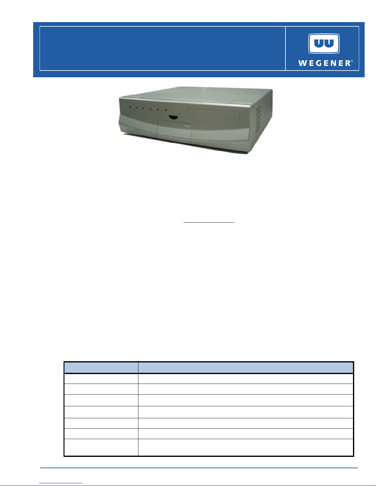
The Wegener iPump 622 Enterprise Media Server is an integrated satellite receiver and video
server. It receivers real-time broadcast-quality transmissions via a QPSK L-band input while it
simultaneously receives IP data files from either a satellite or terrestrial IP connection. It supports
streaming video and audio services via routing, recording, or direct playback. It can even convert
traditional MPEG satellite channels into locally streamed services. Additional information may be
found on the Wegener web site at: www.wegener.com
iPump 622
Streaming Media Decoder
Installation Quick Start Guide
.
Unpacking and Inspection
The box containing the unit should include:
the iPump 622 Enterprise Media Server a UL Safety Sheet
this Quick Start Guide an AC power cord
an IR remote control bagged accessories
Carefully unpack the unit and the ac power cord and inspect for ob vious sign s of physica l damage
that might have occurred during shipment. Any damage claims must be reported to the carrier
immediately. Be sure to check the package content s carefully for important documents and
materials.
NOTE: Save the original packing materials and shipping containers in case the unit must be
returned for repair. Packing the unit in another container in such a way that the unit is
damaged will void the warranty.
Environmental Operating Conditions and Physical Specifications
The table below lists the iPump 622 Environmental Limits and Physical Specifications
ITEM/LIMIT SPECIFICATION
Use Indoor
Altitude Up to 2000 meters
Temperature Range
Relative Humidity (max.)
Weight ~20 pounds or 9.1 kilograms
o
C to 35o C
10
80% for temperatures up to 31
o
C decreasing linearly to 50% relative humidity at 35o C
Dimensions (H x W x D) 4.49" x 15.35" x 14.45" or 114.0 mm x 390.0 mm x 367.0 mm
Input Power Rating 100 to 127 V, or 200 to 240 V AC, 60/50 Hz, 5/3A, Power Supply (115/230V selectable
www.wegener.com 622 QSG-800067-02 Rev. B.fm 1
switch)
Page 2
QUICK START GUIDE
Desktop Installation and Circuit Protection Requirements
To set up the iPump 622 in a desktop environment, place the unit on a flat surface where it will not
be subject to spills or impacts. Route cables to the unit so that they will not be hit or pulled, causing
damage to the connectors or to the unit itself. Ensure that there is a sufficient flow of cool air
around the unit so that its operating ambient temperature range is not exceeded.
System Setup
When connecting the
iPump 622 unit to the power supply, review the r atings of all equipment in the
circuit to ensure that the branch circuit, as well as the power source, will not be overloaded. Also
make sure that a protected power strip is used to attach it to the power supply.
WARNING: FCC-Mandated Suppression of Radio Frequency Emissions
This is a
Class A product. In a domestic environment this product may cause radio
interference for which the user may need to take mitigating action. If the Ethernet port
has a cable connected to it, that cable must be properly shielded and grounded to
minimize RF emissions that could interfere with nearby equipment.
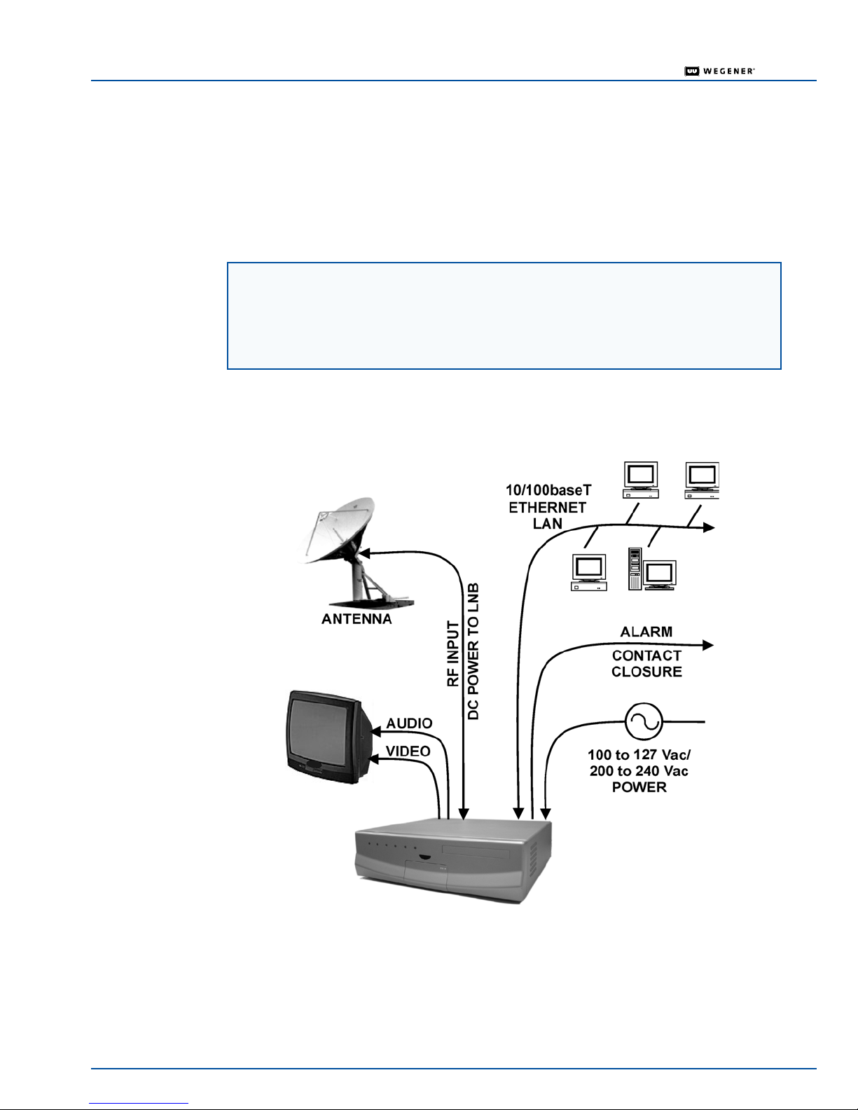
This figure illustrates the basic system setup for an iPump 622:
2 622 QSG-800067-02 Rev. B.fm www.wegener.com
Page 3
Front and Rear Panel Views
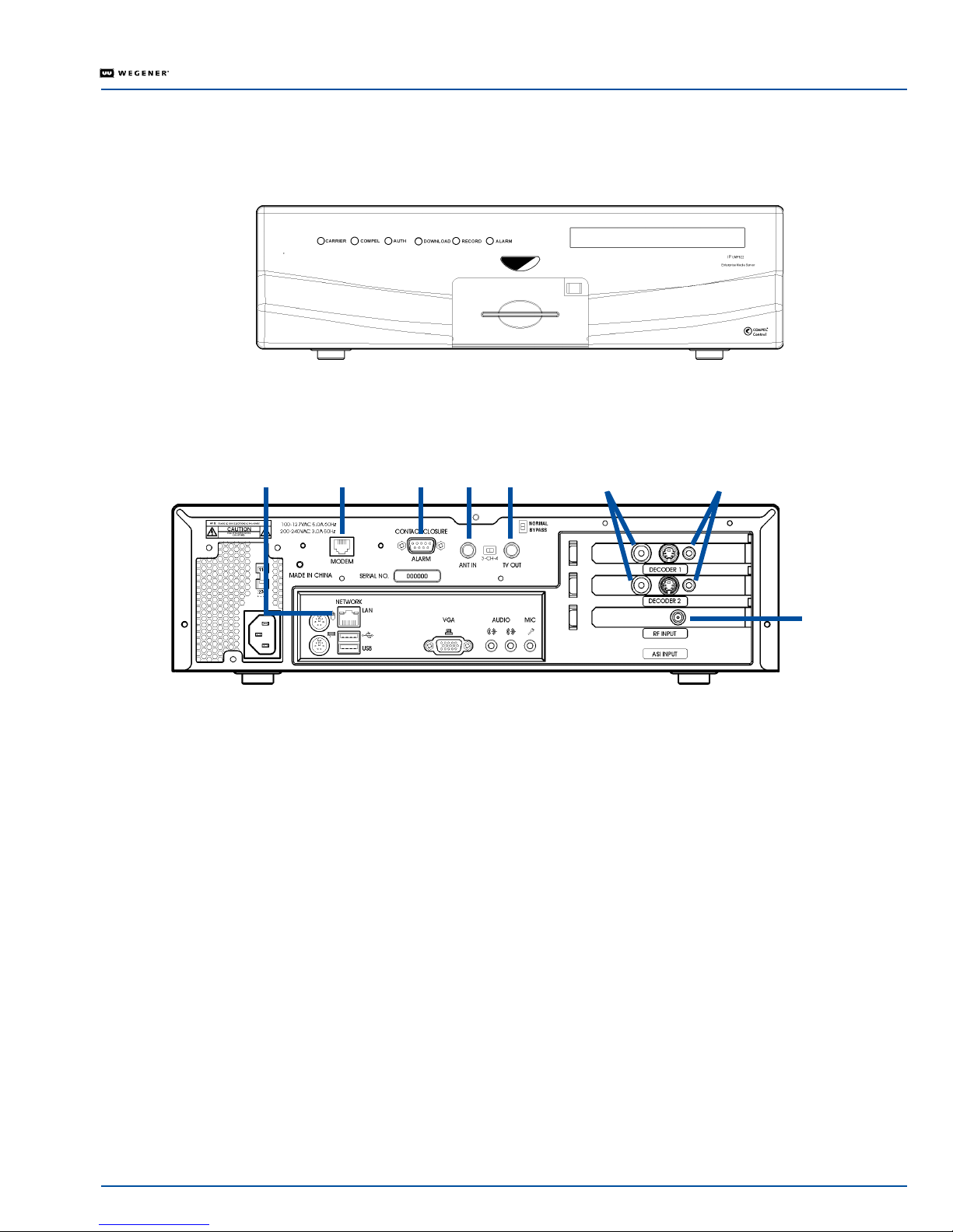
The front and rear panels of the iPump 622 are shown in Figures 1 and 2.
Figure 1: iPump 622 Enterprise Media Server Front Panel
Figure 2: iPump 622 Rear Panel and Connectors
QUICK START GUIDE
ethernet
port
modem
port
alarm
port
ANT
port
IN
TV
OUT
port
audio portsvideo ports
RF
input
port
Rear Panel Connections
For iPump 622 setup, properly connect the rear panel ports with the cables as detailed below. See the iPump
Reference Manual for complete connector and signal details.
Connect the L-band output from your antenna's LNB to the iPump's RF input port [950 to 2150
MHz; female Type F connector with extender cable attached or BNC connector if your unit has the
optional ASI input.]
Connect a suitable monitor to the iPump's audio port. [An optional, auxiliary audio port is also avail-
able. A 1/8-inch stereo output jack is the connector for each audio port, but a 1/8-to-RCA adapter is
included in the accessories bag.]
Connect a suitable video monitor to either the iPump's video port or the TV OUT port. [Video port is
a female, 4 pin mini DIN (S-video) connector. An SVD-to-RCA adapter is included in the accessories
bag.] The Normal/Bypass switch must be in the Normal position disabling the TV OUT port. To use
the TV OUT port, the switch must be in the Bypass position, disabling the Decoder 1 Video Port.
[Use the Channel 3/4 RF Modulator switch to select the appropriate output.]
NOTE:
If your iPump 622 is equipped with two decoders, then repeat the connections for the
audio & video ports.
Connect your LAN line to the iPump's Ethernet port [10/100baseT; female RJ-45 connector.]
The Alarm port on the rear panel may be used to provide a contact closure during alarm conditions
or on command from Compel.
www.wegener.com 622 QSG-800067-02 Rev. B.fm 3
Page 4
QUICK START GUIDE
IR Remote Control
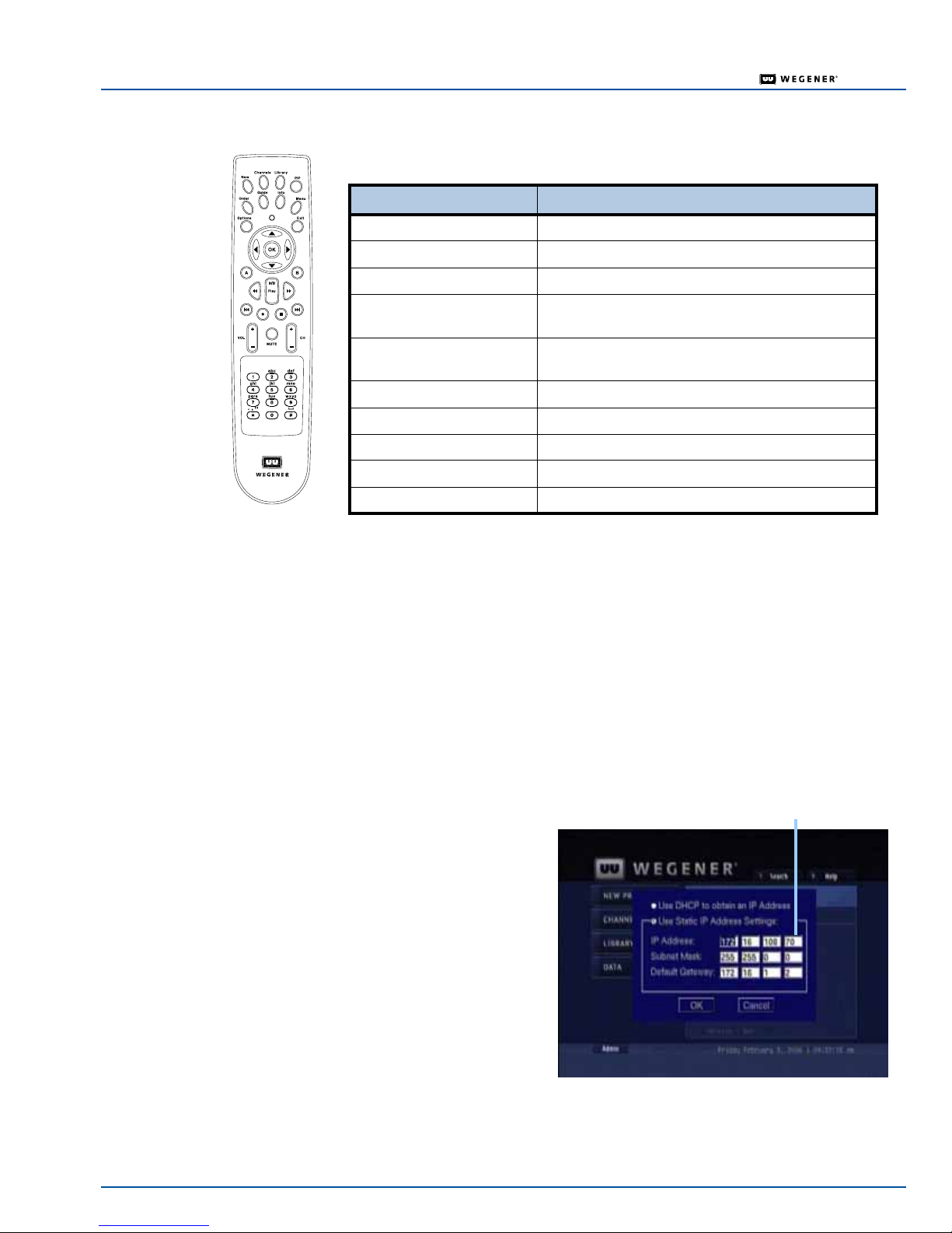
To perform many of the iPump 622 functions, including setup, you’ll need to use
the IR remote control included with your bagged accessories.
Key Function
Arrow keys Navigate through the menus and selects items
OK key Enter or select
Number keys Accepts numbers
Order button Goes to live TV and the new, channels, guide info,
and menu keys all bring up the overlay screen
Library key Brings up the IP settings menu when the admin
screen is active
FF (>>) Fast Forward
RW (<<) Rewind
Play Play
Stop Stop
PIP key Brings up the menu with Picture-in-Picture
On-Screen IP Setup Procedure
With the iPump 622 connected to a video monitor , you can setup, vie w, or change the iPump 622's
IP settings using the remote control.
1) Ensure that your video monitor is connected to the
2) To access the on-screen IP setup screen, select the
(On-Screen Display) menu and press the
3) When the IP Setup screen displays, use the arrow keys to na vigate to each of th e input or
selection fields.
4) Use the
OK key to select the option button for either DHCP (automatic) or Static (manually
input) IP address.
NOTE: If Static is selected, then use
the number keys to enter the IP
numeric entries.
In some cases, it may be
necessary to set specific values
for the IP and Subnet
addresses. Consult your
network administrator.
When entering the IP address
in the OSD, do not include the
leading zeros. For example, IP
address
supplied by the network
administrator) must be entered
as
128.92.50.4 in the OSD.
iPump video port labeled Decoder 1.
Admin button on the main OSD
Library key on the remote.
Static IP addres s with no
leading zeros
128.092.050.004 (as
5) To accept the setup, navigate to the
setup, navigate to the
setup for the
4 622 QSG-800067-02 Rev. B.fm www.wegener.com
OK button and then press the OK key. To cancel the
CANCEL button and then press the OK key. This completes the IP
iPump 622.
Page 5
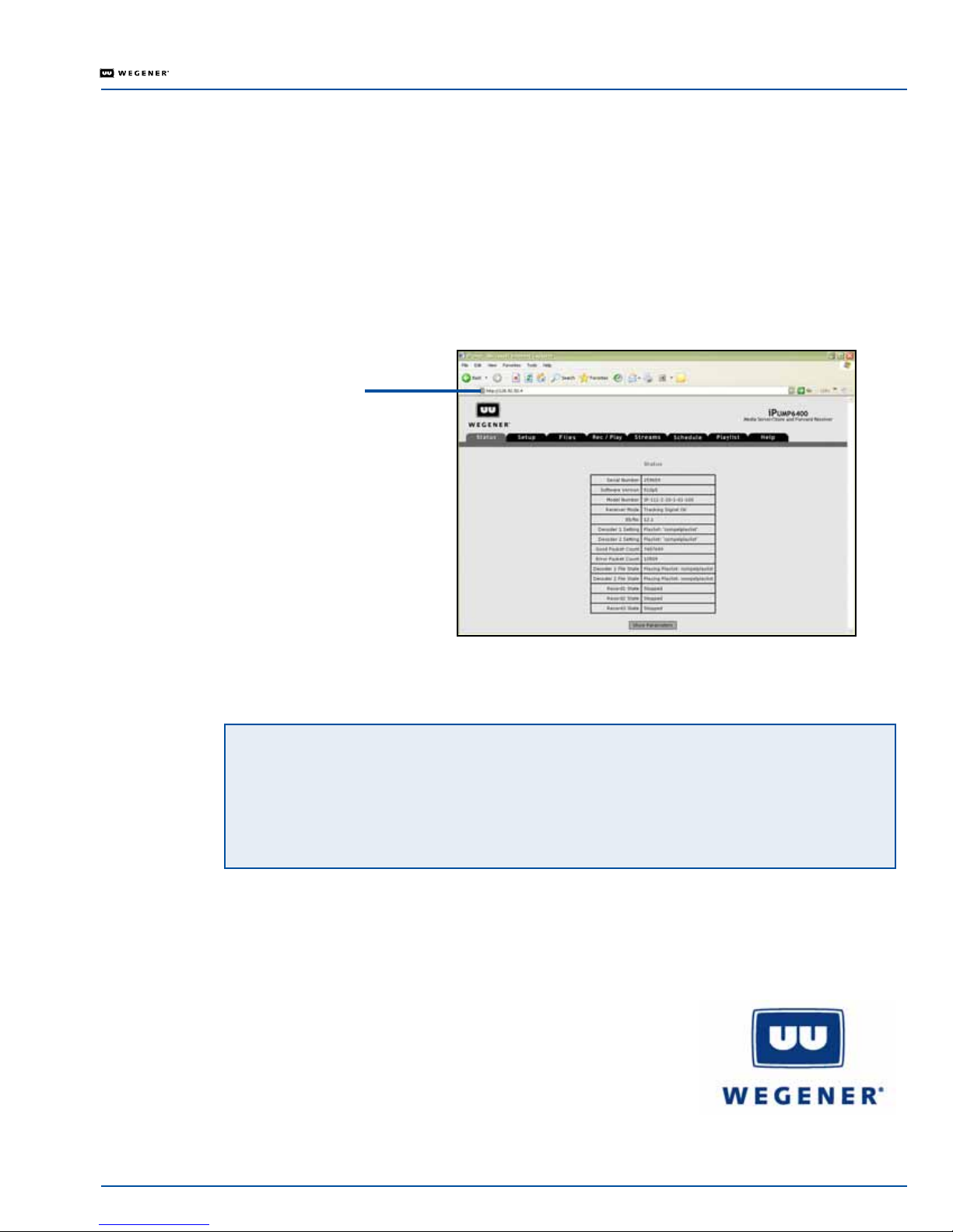
Web Browser Access
When entering the IP address in the web browser, do not include the leading zeros. For example,
IP address
128.92.50.4 in the web browser.
QUICK START GUIDE
128.092.050.004 (as supplied by the network administrator) must be entered as
1) Ensure that your
2) From the computer connected to the
LAN line is connected to the iPump Ethernet port.
iPump 622, open a current-version internet browser.
3) In the browser's address field, enter the IP address noted from the OSD menu. The
tab of the
iPump 622 web browser appears.
Figure 3: iPump 622 web browser Status tab
IP address with
no leading zeros
Status
Warranty
The following warranty applies to all Wegener Communications products:
All Wegener Communications products are warranted against defective materials and workmanship for
a period of one year after shipment to customer. Wegener Communications' obligation under this
warranty is limited to repairing or, at Wegener Communications' option, replacing parts, subassemblies,
or entire assemblies. Wegener Communications shall not be liable for any special, indirect, or
consequential damages. This warranty does not cover parts or equipment that have been subject to
misuse, negligence, or accident by the customer during use. All shipping costs for warranty repairs shall
be prepaid by the customer. There are no other warranties, express or implied, except as stated herein.
Technical Support
In the event that the unit fails to perform as described, contact Wegener Communications
Customer Service at:
Corporate Office: Service Department:
WEGENER WEGENER
1 1350 Technology Circle Customer Service
John's Creek 359 Curie Drive
Duluth, GA 30097 Alpharetta, GA 30005
www.wegener.com 622 QSG-800067-02 Rev. B.fm 5
 Loading...