

Page 1
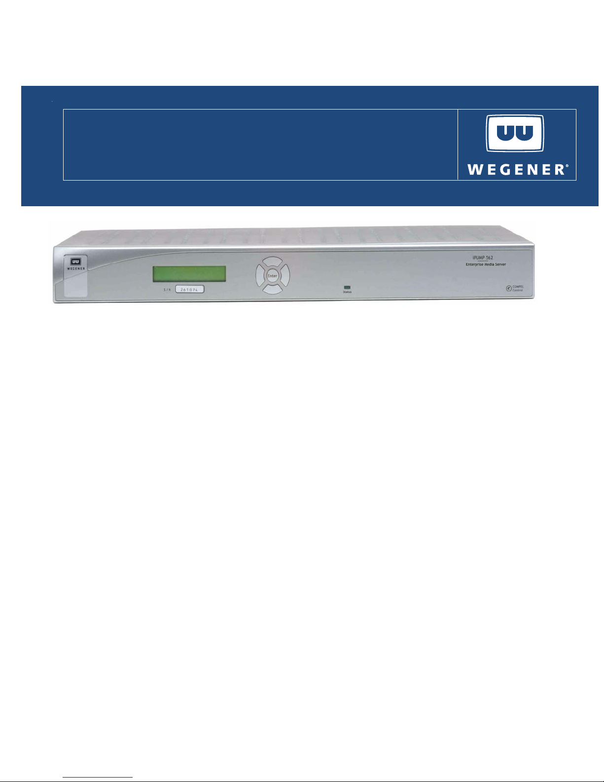
iPump 562
Digital Media Server
User’s Manual
General Information
The WEGENER iPump 562 is a digital media server capable of decoding satellite signals or IP streams or playing stored
content from its internal hard disk drive.
Features
Supports DVB-S QPSK, DVB-S2 QPSK, and DVB-S2 8PSK symbol modulation formats
Supports decoding MPEG-2 and MPEG-4/H.264 compression
Supports PAL and NTSC standard definition video output formats via composite video outputs
Supports 720p and 1080i high definition video output formats via HDMI and YPbPr component outputs
Plays single transport stream files or playlists
Supports Wegener’s Compel control system via RF or IP
Supports Wegener’s conditional access system
Supports DVB sub-titling and teletext services
Supports Digital Signage
Supports decoding/rendering of closed captioning or passthru to TV for decode
Receives file downloads via Compel Assured File Delivery system
Decodes IP multicast and unicast streams
Two relay outputs, both can be user controllable or one assigned to alarms
One GPIO input used for triggered playback of files/playlists
RS232 serial port that can be assigned to terminal mode or printer mode
SNMP monitoring
S/PDIF digital audio output, linear PCM or bitstream
Optional IR remote control
.
Compel™ Network Control
Compel gives you the power to manage a network of iPump562’s and other Unity IRDs with unparalleled functionality. With its
unique network management features, such as grouping, receiver control and scheduling, the operator can command
individual groups of receivers to switch, tune, or "output" video or data targeted specifically for that one receiver or group of
receivers. This ability can be utilized for unequalled disaster recovery for business critical operations.
www.wegener.com 800092-02 Rev. C 1
Page 2
IPUMP562 USER’S MANUAL
Environmental Operating Conditions and Physical Specifications
Item/Limit Specification
Use Indoor
Altitude Up to 3048 meters
Temperature Range 10o C to 40o C
Relative Humidity (max.) 80% for temperatures up to 31o C decreasing linearly to 50% relative
Weight 7.5 pounds or 3.4019 kilograms
Dimensions (H x W x D) 1RU (1.75"x 16.5"x 11.5" or 44.45 mm x 419.1 mm x 292.1 mm)
Input Power Rating for iPump 562 12VDC 5.0A
Input Power Rating for inline power
supply
Rear Panel Connections
o
humidity at 40
C
100-240VAC, 50/60Hz, 1.5A
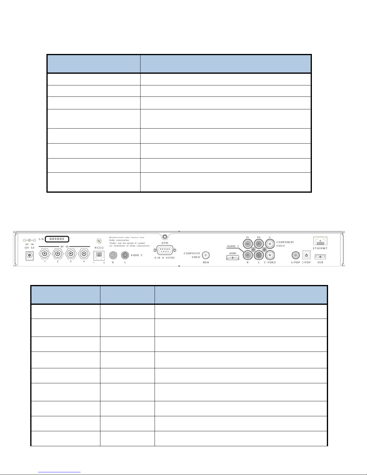
iPump 562 rear panel view
iPump 562 Rear Panel Connections
Signal Connector Description
DC IN
RF IN - Port 1
Male Power Jack +12 VDC @ 5A
Type F 950 to 2150 MHz signal accepted. LNB power and Universal/Astra
signaling available
RF IN - Port 2, 3, 4
RS232 Port
Audio OUT 2 (L/R)
GPIO
Type F (Optional) 950 to 2150 MHz signal accepted.
RJ-12 Serial Asynchronous Data. May be used for terminal or printer
2 RCA Phono Jacks Audio (stereo or mono L/R assignable)
DB-9 Two Relays rated at 0.1A @ 30 V DC and one GPIO input for
triggered file play.
Composite Video
C-Video
Component Video
RCA Phono Jack Composite Video NTSC or PAL
RCA Phono Jack Composite Video NTSC or PAL
3 RCA Phono Jacks Component SD/HD Video YPbPr
2 800092-02 Rev. C www.wegener.com
Page 3
Audio OUT 1 (L/R
HDMI
S/PDIF
S/PDIF
Ethernet
USB
2 RCA Phono Jacks Audio (stereo or mono L/R assignable)
Type A receptacle High Definition Multimedia Interface (Digital A/V)
RCA Phono Jack S/PDIF Coax Digital Audio
Optical TosLink S/PDIF Optical Digital Audio
RJ-45 Ethernet 10/100 BaseT
USB USB 2.0
Connector Pinouts
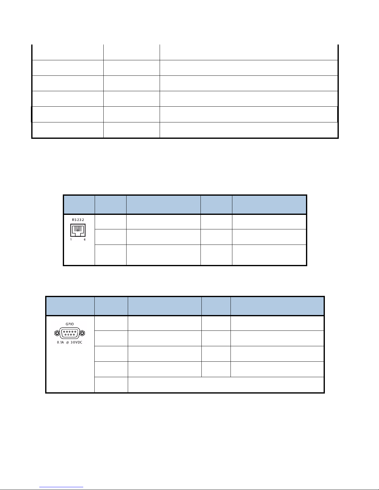
The tables below describe pinout connections for the RJ-12 and DB-9 connector.
Serial Port RS-232 Pinouts
Image Pin Input Output Description Pin Input Output Description
1
No Connection
4
No Connection
2
3
TX Data Output
RX Data Input
5
6
Ground
+5V DC
GPIO Pinouts
Image Pin Input Output Description Pin Input Output Description
1
2
3
4
5
CAUTION: Do not conn ect RJ-12 directly to phone line. Equipment damage may result.
Alarm relay Common
Alarm relay Normally Open
User relay Common
No Connection
GPIO Input
6
7
8
9
Alarm relay Normally Closed
User relay Normally Closed
User relay Normally Open
Ground
www.wegener.com 800092-02 Rev. C 3
Page 4
IPUMP562 USER’S MANUAL
f
Front Panel Controls and Indicators
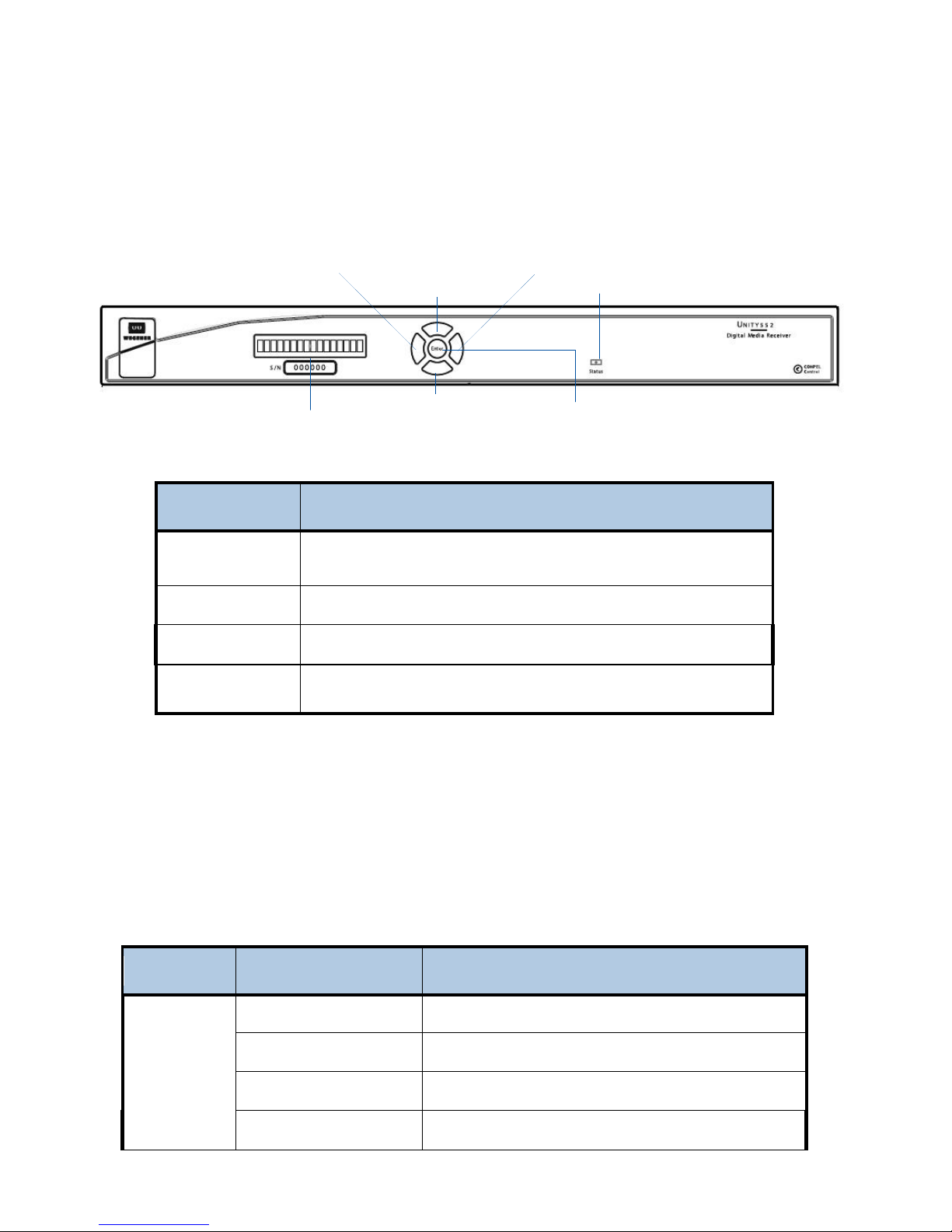
The iPump562 can be controlled via Compel network control, local terminal, and On-Screen-Display. Normally, Compel is the
primary method of controlling the iPump562.
iPump 562 Front Panel
Item Description
LCD
Arrow buttons
ENTER
LED
le
t arrow button
top arrow button
bottom arrow button
LCD screen
iPump 562 Front Panel Controls
Displays unit label and current status unless OSD activated, in which case
it displays the active OSD line.
Arrow buttons activate OSD and navigate through the menus.
Selects next menu level or item selected on OSD.
Indicates status: green for OK, flashing red for alarm, flashing amber for
warning.
right arrow button
LED
Enter button
LED Indications
The iPump562 supplies an operational status using the LED. A steady Green LED indicates that there are no warning or
alarm conditions. The LED will flash when receiving commands from Compel or when downloading files.
If there is a problem, the LED flashes Red for alarm conditions or Amber for warning conditions. In general, alarms indicate
that the unit cannot produce output, while Warnings indicate that, although output is being produced, there is a problem that
could require attention.
iPump 562 Front Panel Status LED Alarm and Warning Indications
Mode LED Status Condition
Red blink = 2 No carrier
Red blink = 4 In recovery
Alarm
4 800092-02 Rev. C www.wegener.com
Red blink = 5 Eb/No alarm
Red blink = 11 Not authorized
Page 5
Warning
Amber blink = 2 Marginal Eb/No
Amber blink = 5 RF too low
Amber blink = 6 RF too high
Amber blink = 7 Application download failed
Normal
Green Normal operation
LCD Menu Navigation
Operate the iPump 562 from the front panel using the arrow buttons and the LCD as shown above. The LCD will display the
unit label and scroll through the RF carrier settings while the OSD is not active. When the OSD is active, the LCD will display
the current OSD line. The up/down arrows will navigate from line to line. The left/right arrows will navigate through fields.
OSD (On-Screen Display)
You may control or monitor the unit using the OSD and front-panel buttons. With a video monitor attached to the iPump 562
through any of the video output ports of the unit, press any button to activate the OSD. You may use the push buttons to
navigate through the menus displayed to view the existing settings.
OSD Menus
OSD information displays white text on a blue background overlaid on the video output from the iPump 562. View the
The
OSD from a monitor connected to any of the video output ports of the iPump 562 server.
Navigating OSD Menus
Use the arrow and
Enter buttons on the iPump 562’s front panel to navigate and edit the fields on the OSD menus.
iPump 562 Types of OSD Action Fields
Actions
Button
Main Menu Submenu Edit Mode
Enter
right arrow
left arrow exits OSD
up arrow
down arrow
selects submenu or
dropdown list
no action no action moves cursor to right
goes to next or previous
menu item
goes to next or previous
menu item
goes to editable field accepts changes
goes to previous menu level moves cursor to left or
abandon changes
goes to next or previous
menu item
goes to next or previous
menu item
increases value of
highlighted item
decreases value of
highlighted item
www.wegener.com 800092-02 Rev. C 5
Page 6
IPUMP562 USER’S MANUAL
The following menus are subject to change with software revisions. Some menus have an “Exit OSD” or “Done” item, but all
menus can be exited using the left arrow key on the front panel. The OSD will time out after 60 seconds if no key is p ressed,
with the exception of the Signal Strength Meter. Any OSD screen may be “parked” so that it does not time out by pressing the
right arrow key and the enter key simultaneously.
Main Menu
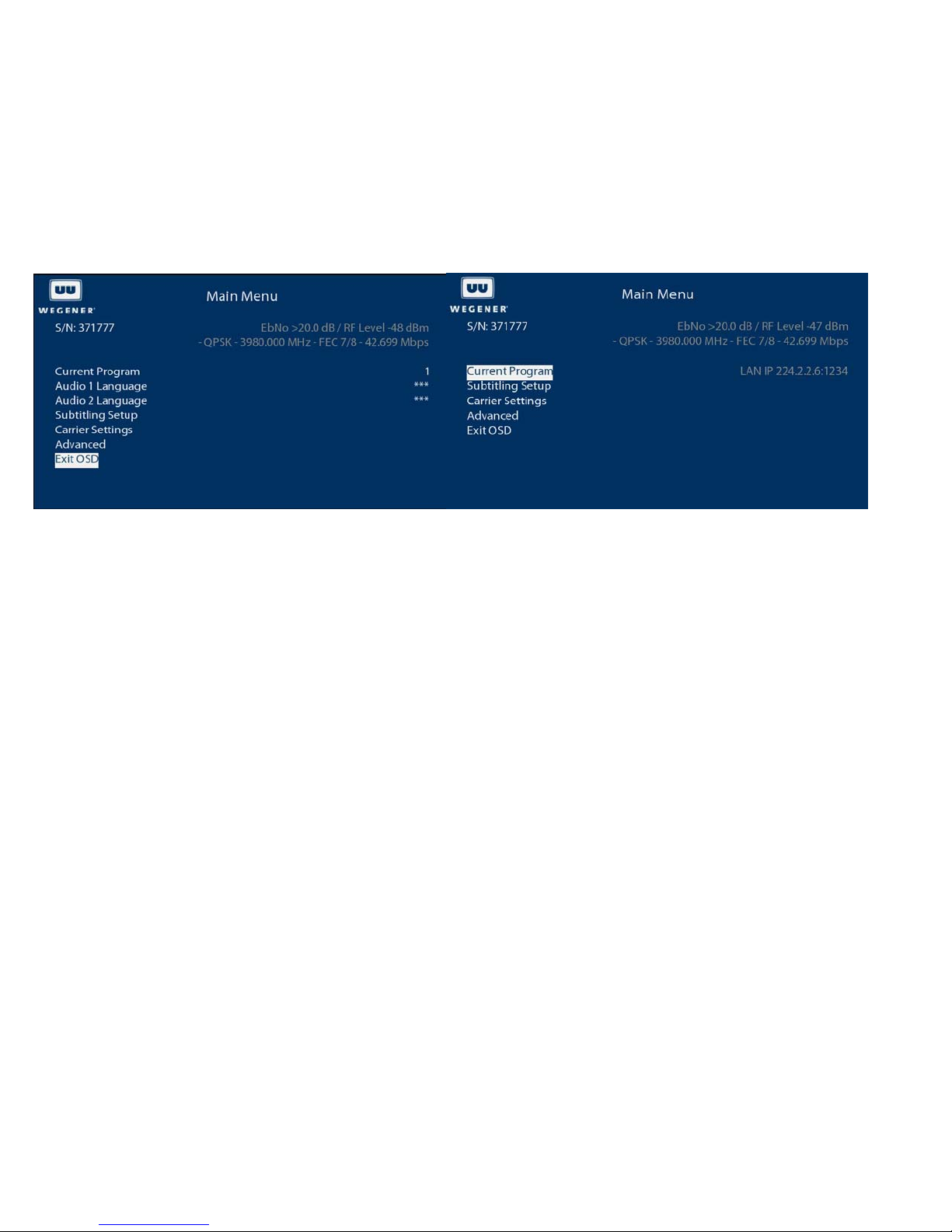
The main menu displays the unit serial number and the currently tuned RF carrier settings, level, and Eb/No at the top.
Current Program
Displays the current program number or descriptor. It may be changed by scrolling through the list of available programs,
using the up/down keys. If the unit is currently decoding a LAN/Ethernet stream, the IP and port of the stream is displayed
here but cannot be changed here. It is selected/changed in the decoder source item of the decoder setup menu.
Audio 1 Language
Displays the current audio program descriptor or “***”, which means the first available audio, for the Audio 1 output. It may be
changed by scrolling through the list of available audio’s, using the up/down keys. If the unit is currently decodi ng a
LAN/Ethernet stream, this will not be in the menu and the unit will decode the first audio in the stream.
Audio 2 Language
Displays the current audio program descriptor or “***”, which means the first available audio, for the Audio 2 output. It may be
changed by scrolling through the list of available audio’s, using the up/down keys. If the unit is currently decodi ng a
LAN/Ethernet stream, this will not be in the menu and the unit will decode the first audio in the stream.
Subtitling Setup
Navigates to the subtitling setup menu which allows enabling/disabling of subtitling and selection of the subtitling languag e.
Subtitling may be enabled only if closed captioning is in the Passthru mode.
Carrier Settings
Navigates to the carrier settings menu, which allows viewing/changing the tuned RF carrier settings, LNB parameters, signal
quality alarm settings and a signal strength meter.
Advanced
Navigates to the advanced menu, which allows more detailed monitor and control functions, such as viewing software
versions, decoder setup, and audio setup.
Subtitling Setup
The subtitling setup menu allows enabling/disabling subtitling display and selection of the subtitling style and language .
6 800092-02 Rev. C www.wegener.com
Page 7

Style
Allows selection of the subtitling style, which may be Normal, Normal + Captioning, or Off. Subtitling data is transmitted in the
two different styles. Selecting the Normal + Captioning will usually mean that sound effects (doors closing, background
noises, etc.) are included for the hearing impaired. What is actually displayed is dependent upon the data transmitted.
Subtitling cannot be enabled if closed captioning is set to anything other than PASSTHRU in the decoder setup menu.
Language
Allows selection of the subtitling language when subtitling is enabled. The languages listed are those received in the
transmitted subtitling data.
www.wegener.com 800092-02 Rev. C 7
Page 8
IPUMP562 USER’S MANUAL
Carrier Settings
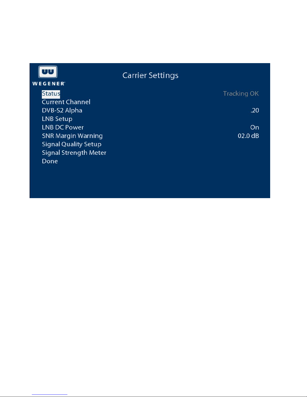
The carrier settings menu allows viewing/changing the tuned RF carrier settings, LNB parameters, signal quality alarm
settings and a signal strength meter.
Current Channel
Allows editing of RF tuning parameters, frequency, data rate, FEC rate, program number, etc.
DVB-S2 Alpha
Adjusts the receiver RF filter characteristics. Options are .20, .25, and .35. This setting only applies to DVB-S2 symbol
modulated RF carriers.
LNB Setup
Allows editing of LNB type and frequency.
LNB DC Power
Allows enabling or disabling of LNB power insertion on RF port 1. The voltage is nominally 18Vdc with a 350mA load.
8 800092-02 Rev. C www.wegener.com
Page 9
SNR Margin Warning
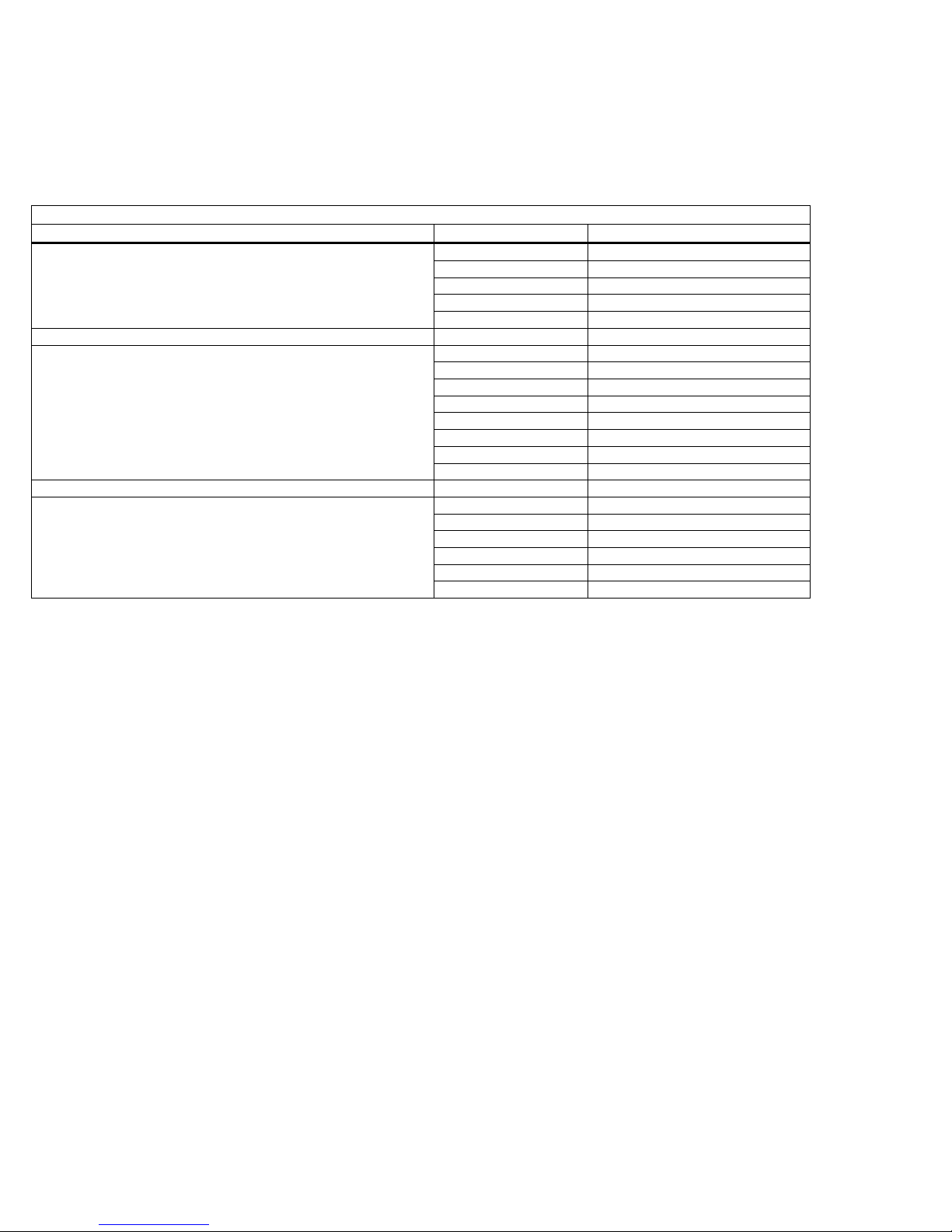
The receiver will display a warning when the signal to noise ratio (Eb/No) reaches this many dB above the alarm level. The
alarm level is based on the modulation format and FEC rate:
Eb/No Alarm Levels (dB)
Modulation FEC Rate Eb/No Alarm Level
2/3 5.00
DVB-S QPSK 3/4 5.50
5/6 6.00
7/8 6.40
1/2 1.03
3/5 1.46
DVB-S2 QPSK 2/3 1.87
3/4 2.29
4/5 2.65
5/6 2.97
7/8 3.71
9/10 3.88
3/5 2.96
2/3 3.63
DVB-S2 8PSK 3/4 4.40
5/6 5.38
8/9 6.44
9/10 6.68
1/2 4.50
Signal Quality Setup
Allows editing of the number of errored seconds per minute at which to display an alarm.
Signal Strength Meter
Displays a meter showing signal strength and Eb/No to aid in antenna pea king.
www.wegener.com 800092-02 Rev. C 9
Page 10
IPUMP562 USER’S MANUAL
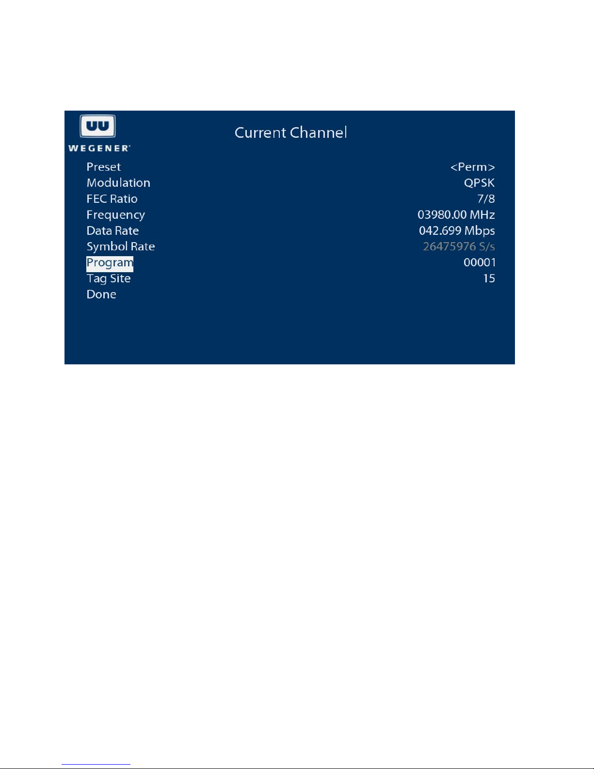
Current Channel
The current channel menu allows viewing/changing the tuned RF carrier settings.
Preset
Allows selection of a channel defined in the settings table, the permanent source, or last commande d. The settings table is a
list of channels (with all tuning parameters). If any exist, they will be listed here. The permanent source is changed when the
iPump562 is tuned to and locked to a carrier. The last commanded is the channel that unit was last tuned to, even though it
may not have locked to it.
Modulation
Allows selection of modulation type. Choices are QPSK, S2QPSK, and S28PSK.
FEC Ratio
Allows selection of FEC inner code rate. Choices are dependent upon modul ation selected.
Frequency
Allows editing of the RF carrier frequency. This frequency value must be a valid value based on the LNB LO setting (C band,
KU band, etc.). The LNB LO frequency should be correctly set before setting this value. The iPump562 receives L band
frequencies in the range of 950 MHz to 2150 MHz. The LNB will down convert the actual transmitted RF carrier frequency to
L band. This entry is the actual transmitted RF carrier frequency.
Data Rate
Allows editing of the data rate of the modulated signal in Mb/s to a resolution of 1 Kb/s.
Symbol Rate
Displays the calculated symbol rate based on Modulation, FEC Ratio. Data Rate, and Pilots (in the case of DVB-S2 carriers).
In the case of DVB-S2 carriers, the iPump562 requires that pilots be inserted in the transmission when the symbol rate is less
than or equal to 10 MS/s and pilots not be inserted when the symbol rate is greater than 10MS/s.
10 800092-02 Rev. C www.wegener.com
Page 11
Program
Allows editing of the program number.
Tag Site
Allows editing of RF carrier tag, which helps identify the carrier. This tag must be inserted in the transmission. A value of 15
means to ignore tags.
LNB Setup
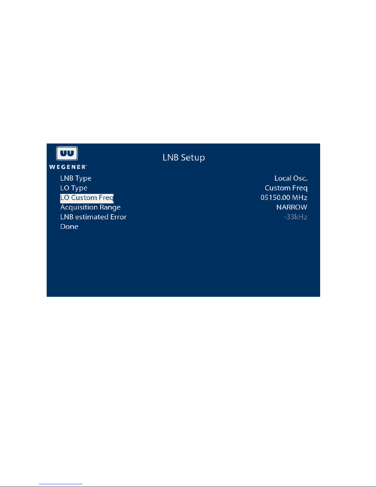
The LNB Setup menu allows editing of LNB type and LO frequency.
LNB Type
Allows selection of the LNB type. The types supported are Local Oscillator (LO) and Universal/ASTRA. If Local Oscillator is
selected, the LO Type and Frequency may be selected. If Universal/ASTRA is selected, the LNB will be controlled via voltage
and a 22 KHz tone in accordance with the ASTRA standard, where the presence of the 22 KHz tone will select Euro High
KU-band (11.70-12.75 GHz) and its absence will select Euro Low KU-band (10. 70-11.70 GHz). The voltage will select the
polarity (13Vdc = vertical, 18Vdc = horizontal).
LO Type
Allows selection of the LO type when the LNB type is Local Oscillator. The choices are Custom Freq (which allows entry of
frequency), std C-band (5150 MHz), US KU-band (10750 MHz), Euro Low KU-band (9750 MHz) and Euro High KU-band
(10600 MHz).
LO Custom Freq
Allows entry of the LO frequency when the LO type is Custom Freq.
Acquisition Range
Allows choice of narrow or wide acquisition range. The narrow ran ge will be dependent upon the carrier symbol rate, while
the wide range will guarantee a minimum of 3 MHz.
www.wegener.com 800092-02 Rev. C 11
Page 12
IPUMP562 USER’S MANUAL
LNB estimated Error
Displays the frequency error of the received carrier frequency versus the tuned carrier frequency.
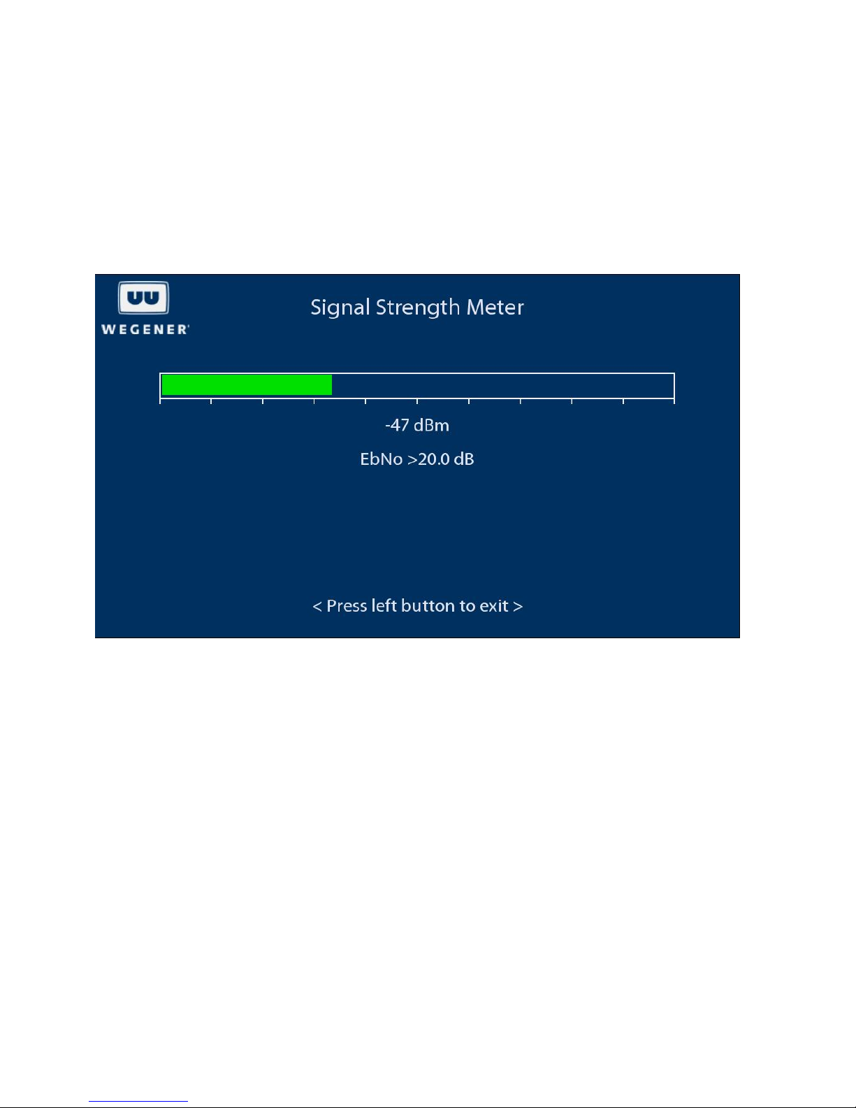
Signal Strength Meter
The Signal Strength Meter displays the input RF level bar graph and value and the Eb/No in real time. This is useful when
peaking an antenna. The bar graph will turn red when the level is outside the limits. This display will remain until the left arrow
key is pressed on the front panel.
12 800092-02 Rev. C www.wegener.com
Page 13
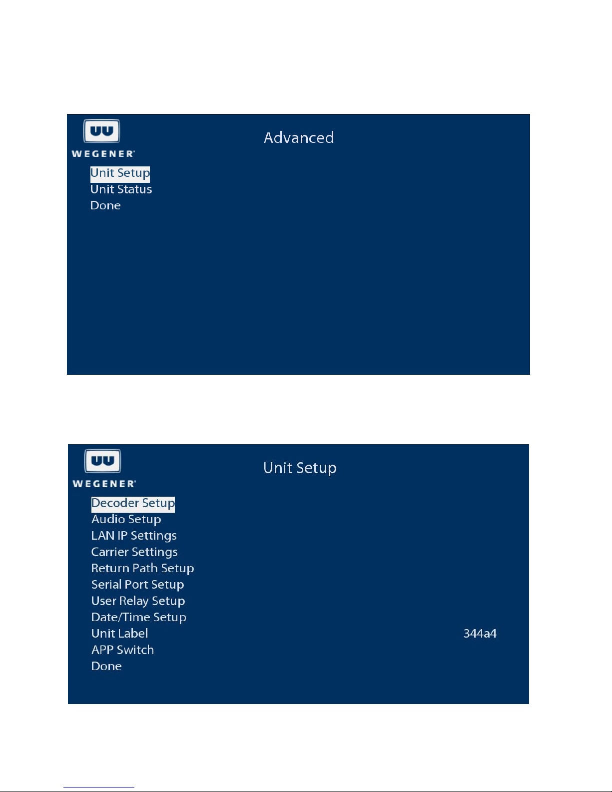
Advanced
The Advanced menu allows navigation to Unit Setup or Unit Status.
Unit Setup
The Unit Setup menu allows the setup of various unit parameters, including decoder setup, audio setup, LAN settings, etc.
www.wegener.com 800092-02 Rev. C 13
Page 14

IPUMP562 USER’S MANUAL
Decoder Setup
Navigates to the decoder setup menu, which allows the user to adjust various parameters of the video output, including
decoder source, scaling options, closed captioning, picture resolution, vertical refresh rate and TV aspect ratio.
Audio Setup
Navigates to the audio setup menu, which allows the user to adjust various parameters of the audio outputs, including
language, routing, attenuation, and S/PDIF output format.
LAN IP Settings
Navigates to the LAN IP Settings menu, which allows the user to set the LAN to DHCP or a static address.
Carrier Settings
Navigates to the carrier settings menu, which allows viewing/changing the tuned RF carrier settings, LNB parameters, signal
quality alarm settings and a signal strength meter.
Return Path Setup
Navigates to the return path setup menu, which allows the user to set an IP for a return path server, which is typically the
Compel control system, so that return path reports may be sent back in response to a command requesting them.
Serial Port Setup
Navigates to the serial port setup menu, which allows the user to select the function and baud rate for the port.
User Relay Setup
Navigates to the user relay setup menu, which allows the user to activate the relays.
Date/Time Setup
Navigates to the date/time setup menu, which allows the user to set the date/time in the unit. When connected to the Compel
control system, the date and time are set by Compel.
Unit Label
Allows the user to enter an alphanumeric label to be displayed on the LCD front panel display. If controlled by Compel, this
will be overwritten by the label for the unit that is entered in Compel.
App Switch
Allows the user to switch to the backup application. The iPump562 has two applications in memory. When application co de is
downloaded to the unit, it is placed into the backup slot. When first executed, the new application code will be run in “testing”
mode. In this mode the application must run for an hour without issue before it will be flagged as a good application. If an
issue occurs, the unit will revert to the previous application. During this “testing” mode no other application code may be
downloaded.
14 800092-02 Rev. C www.wegener.com
Page 15
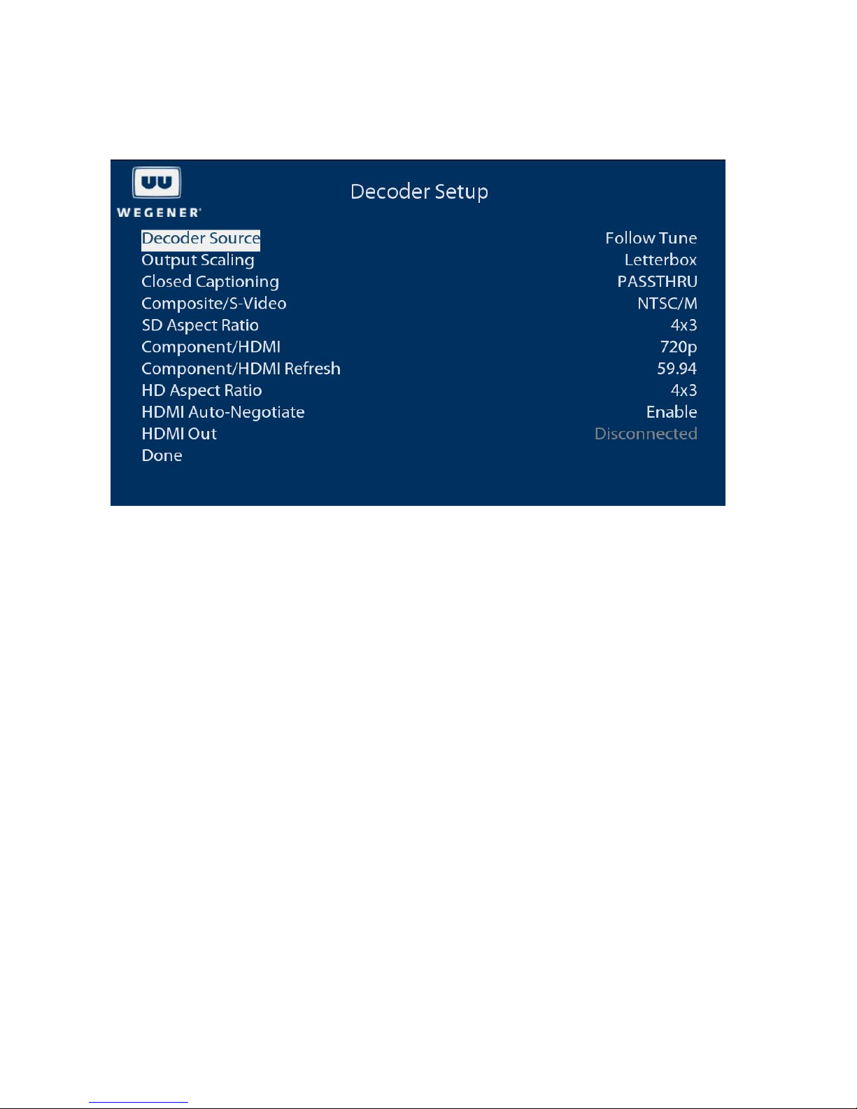
Decoder Setup
The Decoder Setup menu allows the user to adjust the video output of the unit.
Decoder Source
Selects the source of input for the A/V decoder. The Follow Tune indicates that current source is the selected RF carrier and
program number.
Output Scaling
Selects Letterbox or Pan and Scan mode.
Closed Captioning
Selects closed captioning mode. PASSTHRU Mode allows the TV to decode and display closed captioning. Alternatively, the
unit can decode and render closed captioning if the mode is set to CC1-4. CC1-4 may be selected only if subtitling is
disabled.
Composite/S-Video
Selects video output format for the composite video outputs and S-video output (if available).
SD Aspect Ratio
Selects the aspect ratio for the composite video outputs and S-video output (if available).
Component/HDMI
Selects video output resolution of the component and HDMI outputs when HDMI Auto-Negotiate is disabled or HDMI outp ut
is not connected.
Component/HDMI Refresh
Selects the video vertical refresh rate of the component and HDMI outputs when HDMI Auto-Negotiate is disabled or HDMI
output is not connected.
HD Aspect Ratio
Selects the aspect ratio of the component and HDMI outputs.
www.wegener.com 800092-02 Rev. C 15
Page 16
IPUMP562 USER’S MANUAL
HDMI Auto-Negotiate
When enabled, the output resolution and refresh rate of the component and HDMI outputs are set per the DDC data received
from the TV.
HDMI Out
Displays current mode/resolution of the component and HDMI outputs.
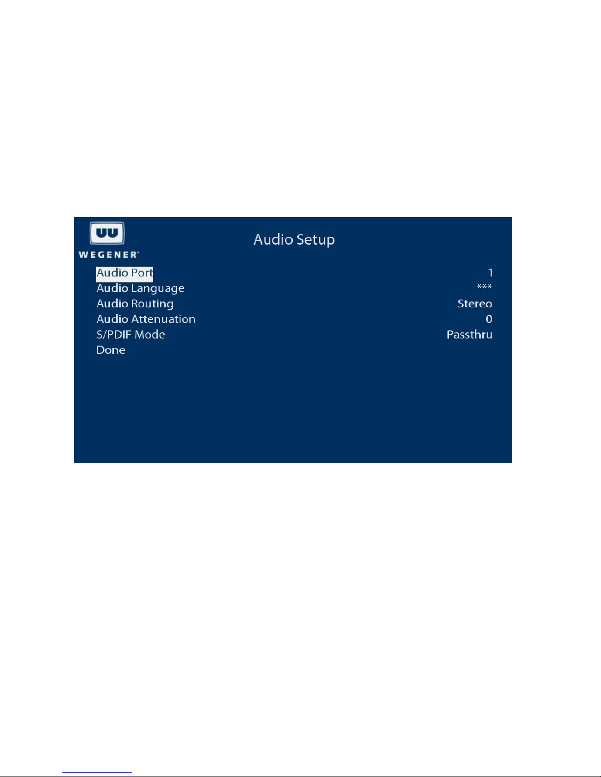
Audio Setup
The Audio Setup menu allows the user to adjust various parameters of the audio outputs, including language, routing,
attenuation, and S/PDIF output format.
Audio Port
Allows selection of display of port 1 or port 2 parameters.
Audio Language
Allows selection of the audio language. Choices include ***, which is the first audio found, and a list of all audio descriptors
found in the transmission.
Audio Routing
Allows routing of program audio channels (Left and Right) to the output connectors for the port. Stereo will route left channel
audio to the white output connector and right channel audio to the red output connector. Or the user may select right on both
or left on both or reverse stereo (routing left channel audio to the red output connector and right channel audio to the white
output connector).
Audio Attenuation
Allows attenuation of the audio, 0 to 20 dB
S/PDIF Mode
Allows selection of PASSTHRU (no decoding will be done, the bitstream is passed), LPCM (Dolby Digital and AAC will be
decoded), or OFF (no output).
16 800092-02 Rev. C www.wegener.com
Page 17
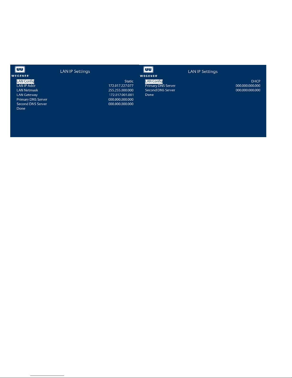
LAN IP Settings
The LAN IP settings menu allows the user to set the LAN to DHCP or a static address.
LAN Config
Allows setting to DHCP or static address. When in DHCP mode, the address will be assigned by a DHCP server if one is on
the network and the address assigned may be found by navigating to the unit status menu and selecting LAN IP info.
LAN IP Addr
Allows entry of the static LAN IP address.
LAN IP Netmask
Allows entry of the static LAN IP netmask.
LAN Gateway
Allows entry of the LAN Gateway address.
Primary DNS Server
Allows entry of the LAN Primary DNS server address.
Secondary DNS Server
Allows entry of the LAN Secondary DNS server address.
www.wegener.com 800092-02 Rev. C 17
Page 18
IPUMP562 USER’S MANUAL
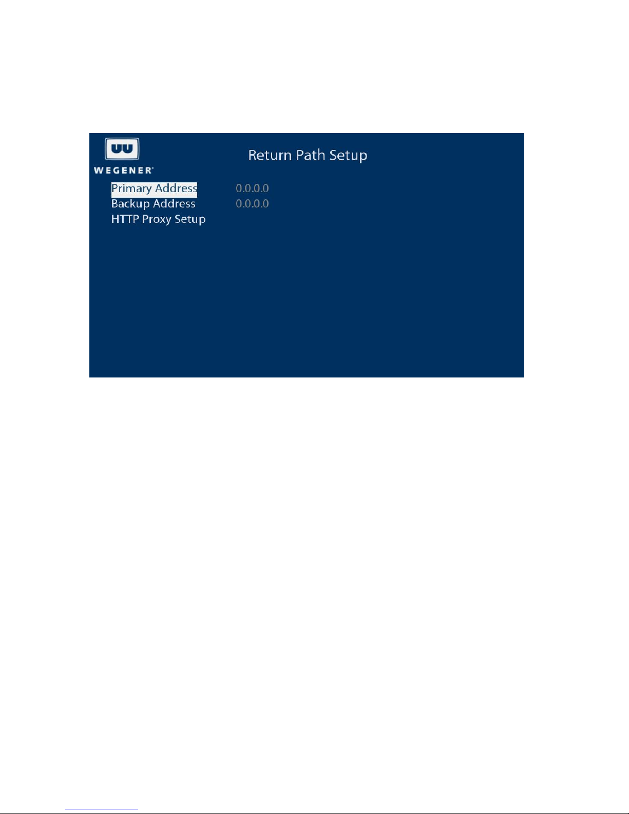
Return Path Setup
The Return Path Setup menu allows the user to set the IP address of the return path server, typically the Compel control
system. Return path reports will be sent to this server.
Primary IP
Allows entry of the primary server IP address.
Backup IP
Allows entry of the backup server IP address. Reports will be sent to this server address when the primary address is
unreachable.
HTTP Proxy Setup
Allows enabling or disabling a proxy server.
18 800092-02 Rev. C www.wegener.com
Page 19
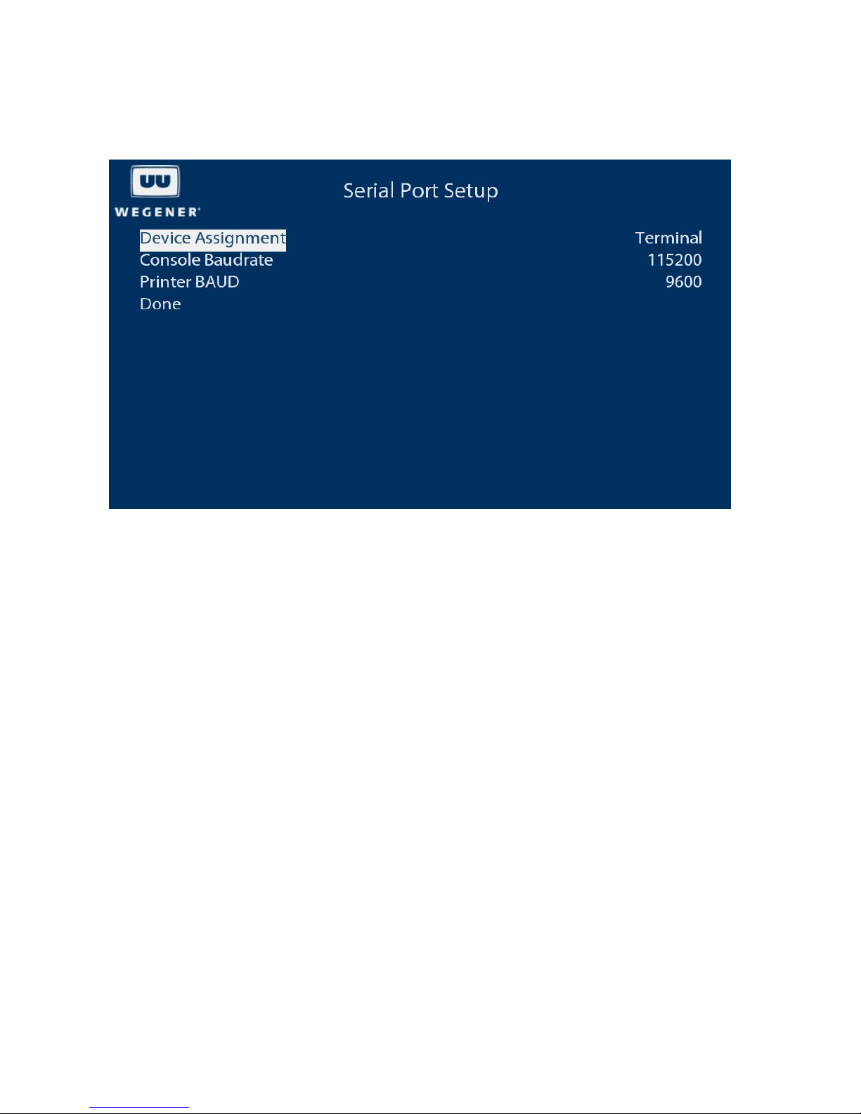
Serial Port Setup
The Serial Port Setup menu allows the user to set the device assignment and baud rates of the serial port.
Device Assignment
Assigns the serial port to terminal or printer.
Console Baudrate
Allows selection of the baud rate to use when in terminal mode.
Printer BAUD
Allows selection of the baud rate to use when in printer mode.
www.wegener.com 800092-02 Rev. C 19
Page 20
IPUMP562 USER’S MANUAL
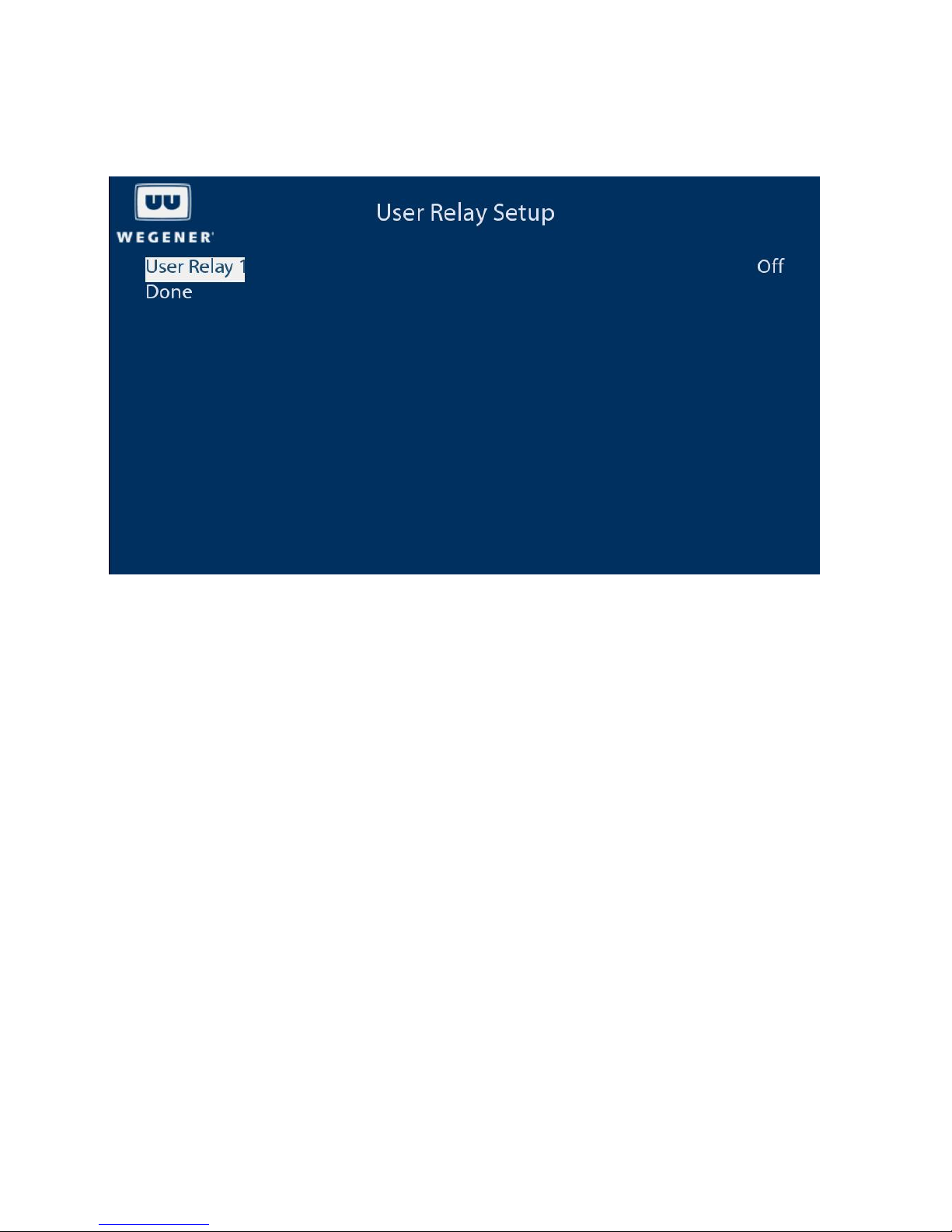
User Relay Setup
The User Relay Setup menu allows the user to control the relays.
Each relay has a normally open and a normally closed contact. Off means de-energized (normal contact states). On means
energized (opposite of normal contact states).
There may be one or two relays displayed here depending upon the alarm relay usage. One relay is reserved for alarms
unless the user configures it to be used for user relay application. This is done via the serial port in terminal mode or the
diagnostics interface of the web interface. The command “alarmrelay user2” will assign the relay for user application and the
command “alarmrelay normal” will assign the relay for alarms. When assigned for alarm s, this relay will b e normally
energized and will be de-energized in the case of an alarm.
20 800092-02 Rev. C www.wegener.com
Page 21
Web Interface
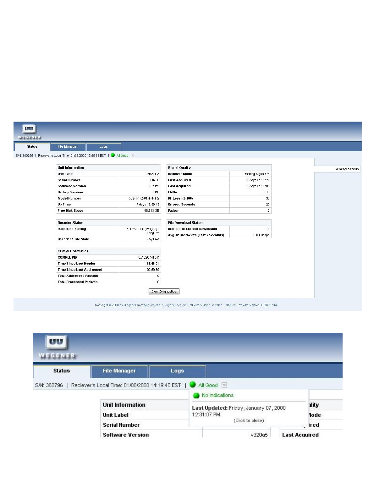
The web interface allows users to view the status and logs of the unit, as well as download assets from the unit. It is designed
to perform best with Mozilla FireFox web browser.
Status view
The status view displays the current status of the unit, including the serial number, software versions installed, decoder
status, Compel statistics, RF signal information, and file download status.
The green LED icon will indicate the state of the LED on the unit and clicking this will show any warnings or alarms, if
present.
www.wegener.com 800092-02 Rev. C 21
Page 22
IPUMP562 USER’S MANUAL
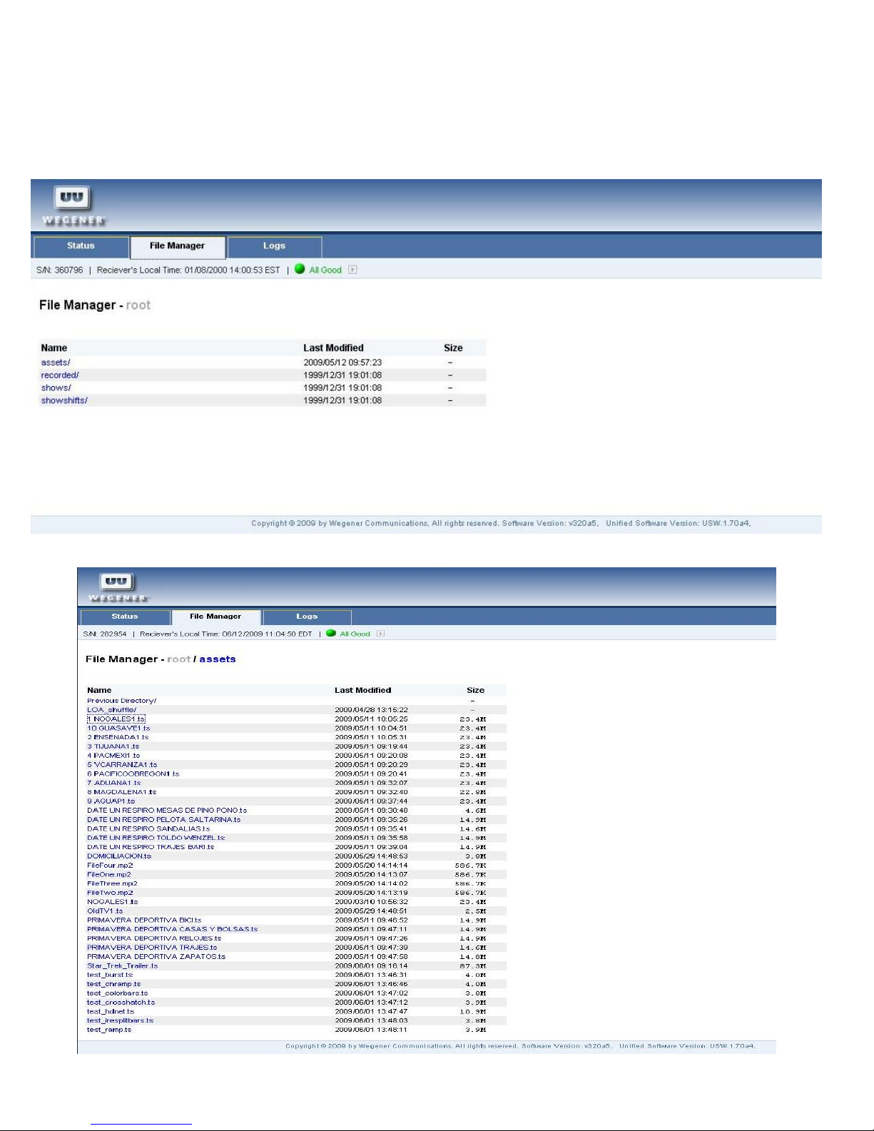
File Manager view
The file manager view allows the user to view the assets currently on the unit. Assets are user provided video, audio, image,
or text files downloaded via the Compel control system.
Click the assets folder to view the list of assets. Assets may be viewed, played or downloaded by clicking on the file name.
22 800092-02 Rev. C www.wegener.com
Page 23
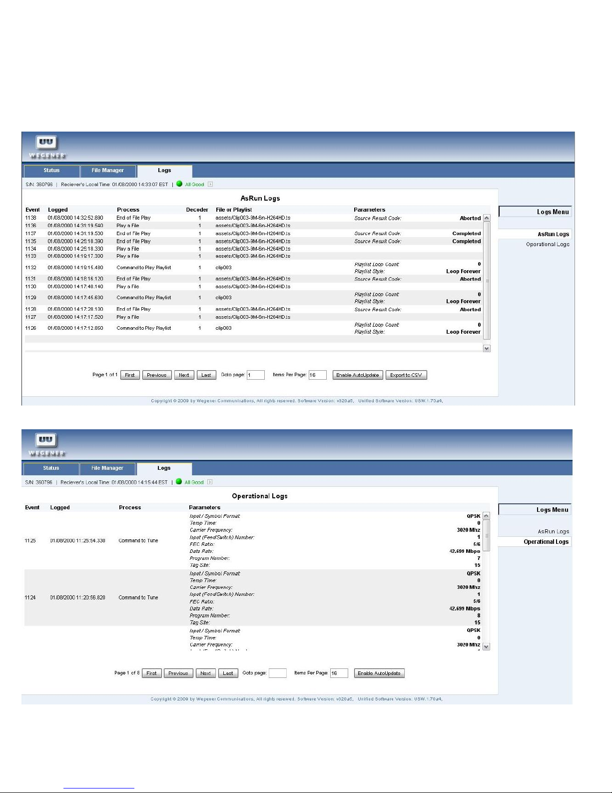
Logs view
The logs view allows the user to view the “as run” log or the “operational” log.
The “as run” log lists all assets that have been played by the unit.
The “operational” log lists any changes in RF signal tuning.
www.wegener.com 800092-02 Rev. C 23
Page 24
IPUMP562 USER’S MANUAL
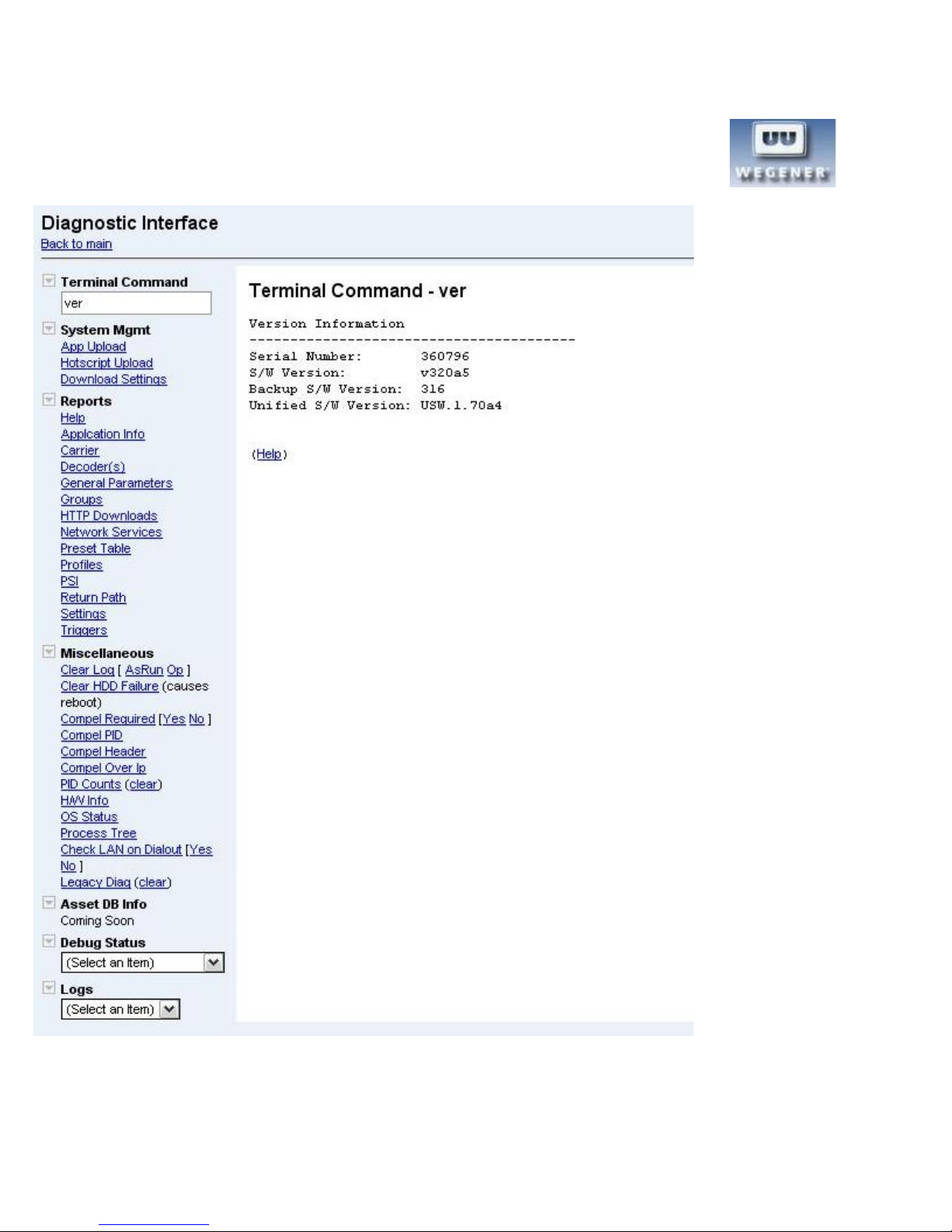
Diagnostics interface
By holding down the control key on the keyboard and clicking the Wegener logo in the top left corner,
a diagnostics interface may be accessed.
From this interface, in addition to many other actions, the user can play a file or playlist of files from the hard disk drive.
24 800092-02 Rev. C www.wegener.com
Page 25

Play file
To play a file, in the terminal command box, type “playfile 1 filename”. The filename must include the path, which should
always begin with “/assets” and the file extension, which should always be “.ts”. Files are MPEG2 transport stream files.
For example, “playfile 1 /assets/myasset/myfile.ts” will play myfile.ts, located in the myasset folder under the assets folder.
Files are considered a temporary insert, that is they play one time and then the iPump562 will return to the previous source.
Play list
A playlist is an .xml file that contains a list of files to play. Playlists are transferred to the iPump562 via Compel.
To play a playlist, in the terminal command box, type “playlist play 1 listname 1”. The listname will be the name only. The
path for playlists is fixed and no extension is included. The last “1” in the command means loop the playlist repeatedly, if the
“1” is omitted or a “0” is typed, the playlist will play only once.
For example: “playlist play 1 mylist 1” will play mylist repeatedly. “playlist play 1 mylist” will play mylist once.
To stop a playlist that is playing repeatedly, change the decoder source:
“decoff 1” will turn off the decoder and there will be no video/audio output.
“decfollowtune 1” will change to the satellite/RF input.
“decodelanip 1 224.1.1.101 8208” will change to the LAN/Ethernet multicast on IP address 224.1.1.101, po rt 8208.
Triggered playback
A file or playlist may be played in response to a trigger signal applied to the GPIO input line, pin 5 on the GPIO connector.
The trigger signal is sent by connecting pin 5 to ground (pin 9) for at least 100mS. The GPIO line should b e discon nected
from ground after the trigger. This is normally done with a momentary switch.
The file or playlist must be queued up for playback before the trigger is applied.
To queue up a file for triggered playback, from the diagnostics interface, enter the following into the terminal command box:
“playfile 1 /assets/myasset/myfile.ts L”
To queue up a playlist for triggered playback, from the diagnostics interface, enter the following into the terminal command
box:
“playlist play 1 mylist 0 L” for one time playback upon trigger.
“playlist play 1 mylist 1 L” for repeated playback upon trigger.
When the iPump562 receives the signal for triggered playback, it will first delay for the amount of time set in the “gpidelay”
variable, which defaults to 0 (no delay). This value may be viewed by typing “gpidelay” into the terminal command box. And it
may set by including a value (in mS).
For example: “gpidelay 5000” will set the delay for 5 seconds.
This delay may be necessary to achieve a reliable, precise playback point in time. This is because it may take some small
amount of time to load and start the decoder, especially in the case of a playlist which has multiple files listed. It is
recommended that 5 seconds delay (5000) be used for triggering a playlist of 4 files. If more than 4 files are in the list, the
delay value may need to be increased
Internet Mode
Placing a unit in internet mode means that the unit will not attempt to tune and will ignore tuner alarms.
To place the unit in internet mode issue the following commands:
“carrierreq 0”
“srchman tunerignore 1”
“reset”
To revert to normal RF operation issue the commands:
“carrierreq 1”
“srchman tunerignore 0”
“reset”
www.wegener.com 800092-02 Rev. C 25
Page 26

IPUMP562 USER’S MANUAL
Compel Method
CAUTION: Changing the method of Compel control should be done with care as it could result in a loss of control if
not set correctly. It is recommended to issue the specific method setup commands mentioned below before issuing
the “compel method” command.
The unit may be controlled via the Compel control system using one of three connection methods, dvbpid, mcast, or http. The
method is set by issuing one of the following commands:
“compel method dvbpid” - This is the default control method. Compel will control the unit by sending commands in the
MPEG transport stream on the the tuned RF carrier. With this method, the PID of the Compel commands must be set in the
unit by issuing the command: “compel pid 1026”. The PID number (1026) is expressed in hexadecimal. This setting must
match the setting in the Compel control system.
“compel method mcast” - Compel will control the unit by sending commands in a multicast IP transmission. The multicast
IP address and port must be set by issuing the following command: “compel mcsetup [address] [port]”, where [address] is the
multicast IP address and [port] is the multicast port number. When using this method, Compel will also deliver assets over a
multicast IP transmission and the multicast address and port for asset delivery must also be set by issuing the following
command: “afd mcsetup [address] [port]” , where [address] is the multicast IP address and [port] is the multicast port number.
“compel method http” - Compel will hold all commands in a database until retrieved by the unit over IP. With this method,
a server IP address must be set in the unit that matches the Compel IP address. This is done with the command: cmplint
srvraddr [address] , where [address] is the Compel IP address. Assets will also be retrieved via this server address.
26 800092-02 Rev. C www.wegener.com
Page 27
Technical Specifications
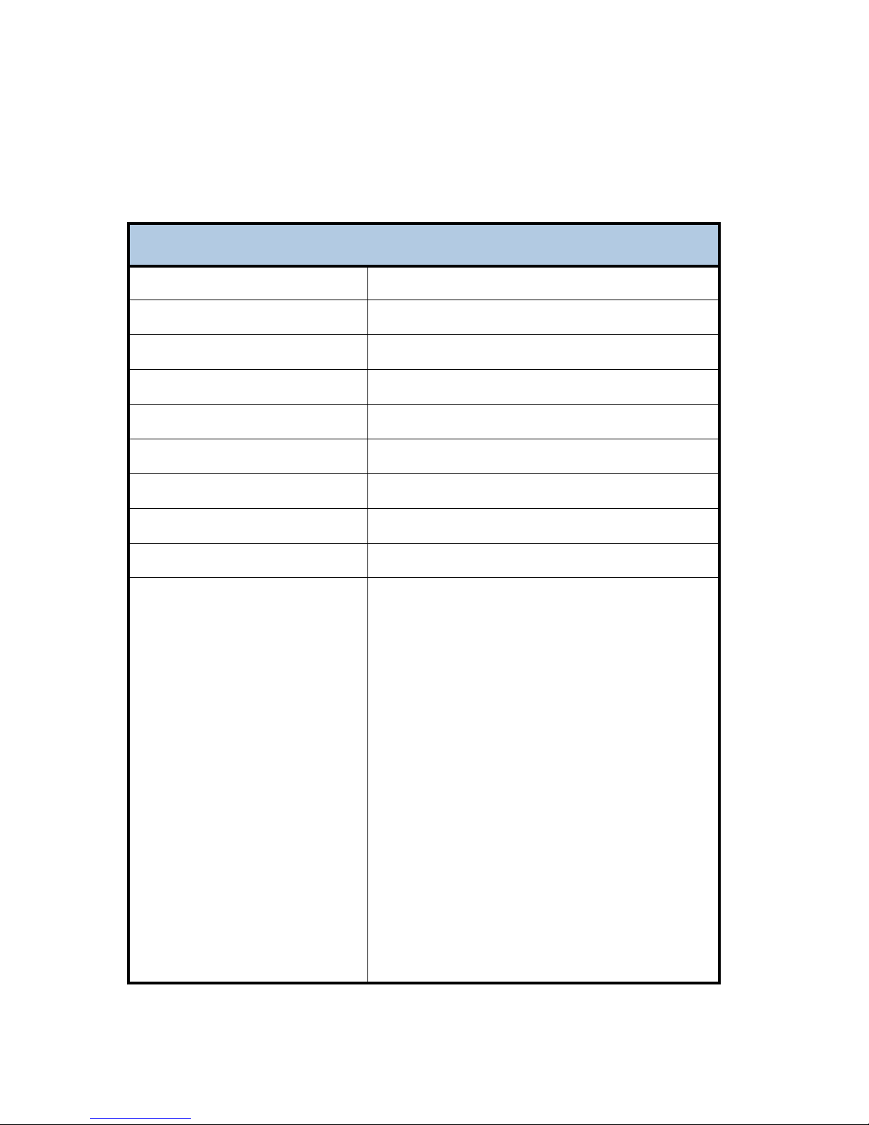
The following tables detail the technical specifications for the iPump562..
RF Characteristics
iPump 562 RF Characteristics
RF Characteristics
RF Input
Input Frequency Range
Input Level Range
Maximum Aggregate Input Power
Input Impedance
Input VSWR
Input Noise Figure
L.O. Leakage at Input
Maximum Symbol-rate
Minimum Eb/No
Connector Type F
950 - 2150 MHz
-25 to -65dBm
-8 dBm at max input signal
75 ohms
< 2.5:1
8 dB MAX at minimum input level
< -55 dBm
DVB- S = 45 Mbps, DVB- S2 = 30 Msps
DVB-S QPSK:
FEC: Eb/No (dB)
1/2: 4.5
2/3: 5.0
3/4: 5.5
5/6: 6.0
7/8: 6.4
DVB-S2 QPSK:
FEC: Eb/No (dB)
1/2: 1.5
3/5: 2.0
2/3: 2.4
3/4: 2.8
4/5: 3.2
5/6: 3.5
8/9: 4.2
9/10: 4.4
DVB-S2 8PSK:
FEC: Eb/No (dB)
3/5: 3.5
2/3: 4.1
3/4: 4.9
5/6: 5.9
8/9: 6.9
9/10: 7.2
www.wegener.com 800092-02 Rev. C 27
Page 28
IPUMP562 USER’S MANUAL
Video Decoder
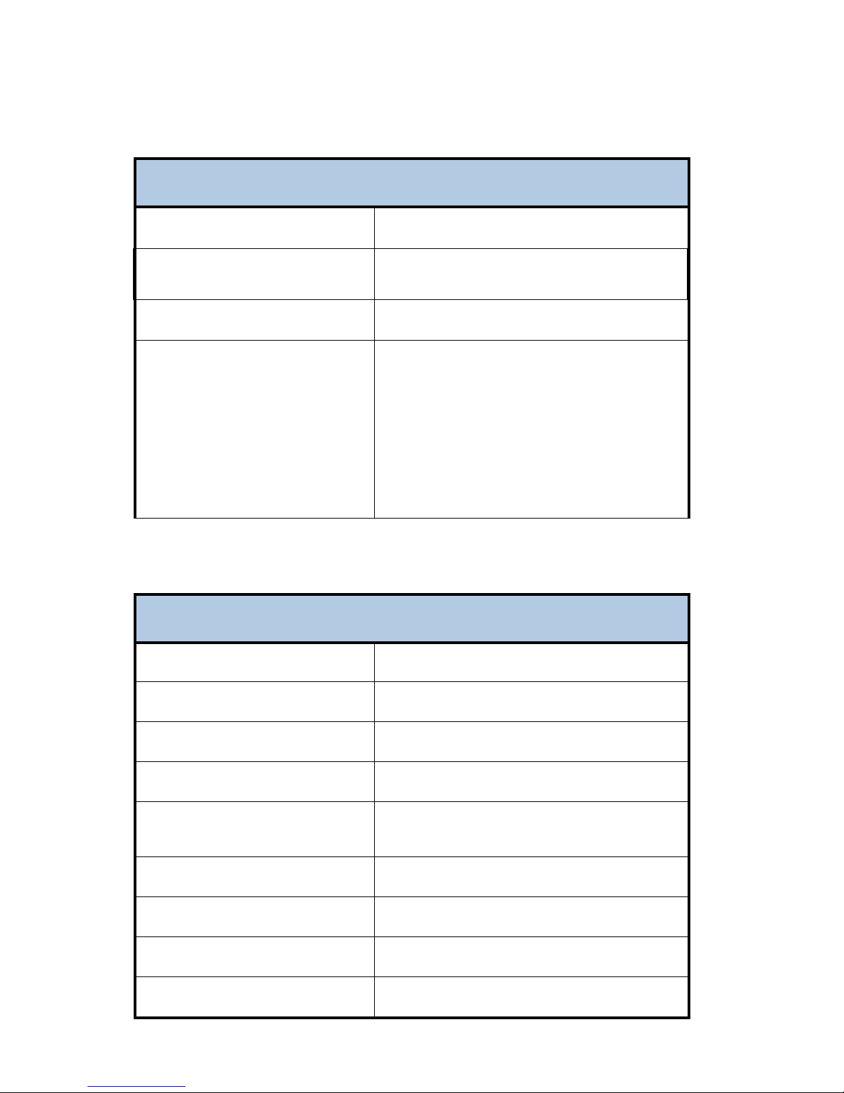
iPump 562 Video Decoder
Video Decoder
Compression System
Color Space Sampling Scheme
Composite Video Output Formats
Component/HDMI Video Output
Formats
Composite Video Output
MPEG-2 and MPEG-4/H.264
4:2:0
4:2:2
NTSC-M, NTSC-J, PAL B/G, PAL 60, PAL N, PAL M
1080I / 60
1080I / 59.94
1080I / 50
720P / 60
720P / 59.94
720P / 50
iPump 562 Composite Video Output
Composite Video Output
Line 21 Closed captioning
TELETEXT
Output Level
Output Impedance
Multi-burst Frequency Response
Differential Gain
Differential Phase
Line Time Distortion
Field Time Distortion
28 800092-02 Rev. C www.wegener.com
Divicom and ATSC EIA-608-B
CCIR/ITU-R Broadcast Teletext System B
1.0 Vp-p, < 5% Deviation
75 Ohms
NTSC: From 0.5 to 4.2 MHz: < +0/-3 dB PAL: From 0.5
to 4.2 / 5.8 MHz: < +0/-3
< 3%
< 3 Degrees
< 2% p-p
< 2% p-p
Page 29
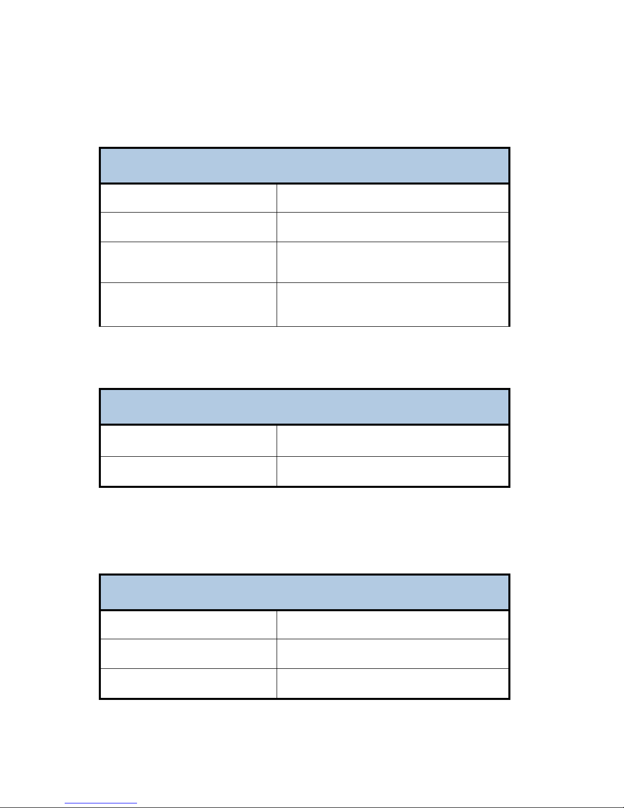
Component Video Output
iPump 562 Component Video Output
Component Video Output
Output Level
Output Impedance
S/N
Frequency Response
Y = 1 Vp-p, Pb/Pr = 700mVp-p
75 Ohms
68 dB unified weighting
Y: 5 to 25 MHz: < +0/-3 dB
Pb: 2.5 to 10 MHz: < +0/-3 dB
Pr: 2.5 to 10 MHz: < +0/-3 dB
iPump 562 Audio Decoder
Audio Decoder
Compression System
Sample Rates Supported
MPEG-1 Layer 2, Dolby Digital, MPEG2 AAC, MPEG4
AAC
44.1 and 48 kHz
Audio Output
iPump 562 Audio Output
Unbalanced Audio Output
Output level adjust range
Output Level-MAX PPL
Impedance
www.wegener.com 800092-02 Rev. C 29
0 to -20 dB attenuation
+9.0 +/- 0.5 dBu
Unbalanced: < 1000 Ohms
Page 30
IPUMP562 USER’S MANUAL
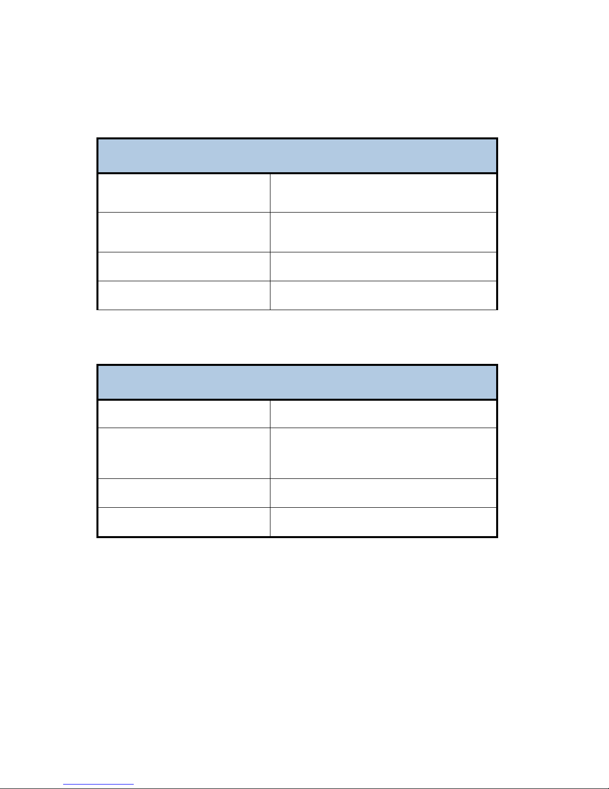
Audio Parameters
iPump 562 Audio Parameters
Audio Parameters
Serial Port
Frequency Response
THD
S/N Ratio
Dynamic Range
RS-232
Selectable services
20Hz to 20 kHz, +0.5/-2.0 dB 50Hz to 15 kHz, +0.5/-
1.0/-0.5 dB
< 0.5%
> 68 dB (22 Hz to 20 KHz) unweighted
86 dB unweighted
iPump 562 Serial Port
Serial Port
RJ11
Printer mode: character-based async output.
Terminal mode: command line interface monitoring
and control.
Baud Rates
Format
2400 to 115200 baud
8 data-bits, one start, one stop-bit, no parity
30 800092-02 Rev. C www.wegener.com
Page 31
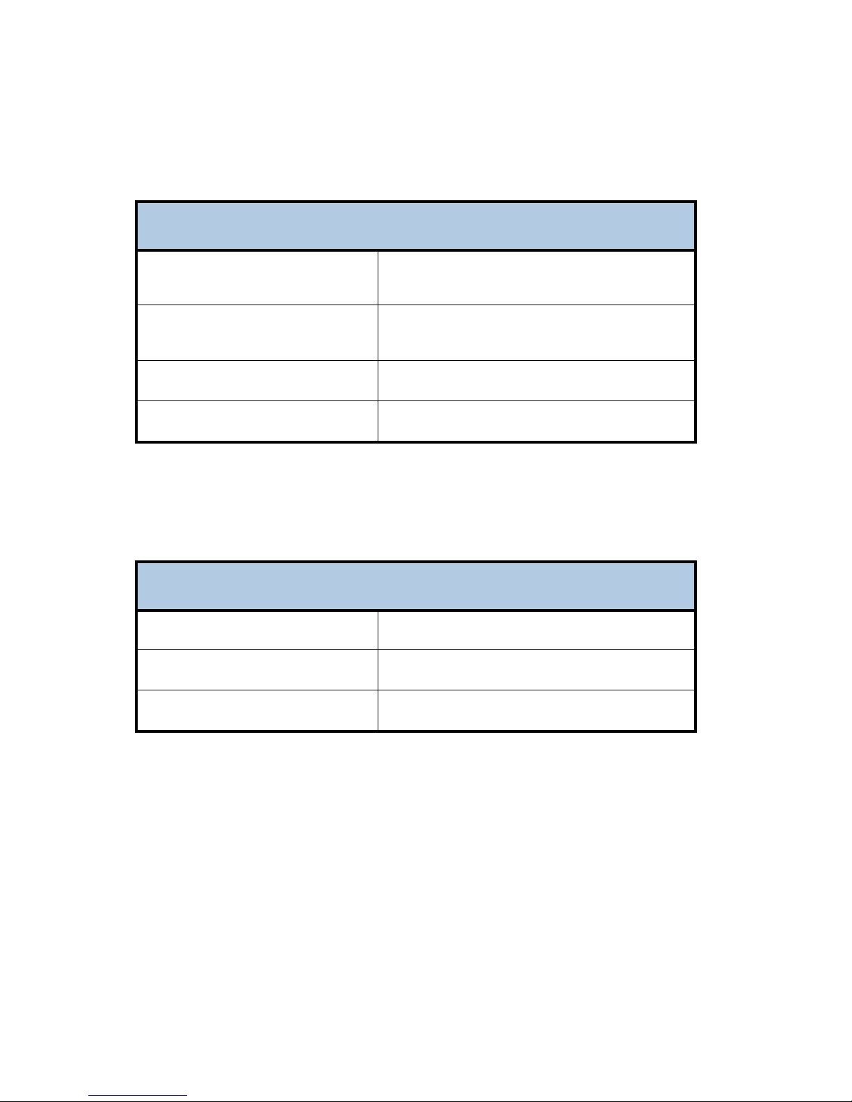
LNB DC Power (RF Port 1 ONLY)
iPump 562 LNB DC Power (RF Port 1 ONLY)
LNB DC Power (RF Port 1 ONLY)
AC Power
Voltage
22 KHz tone
Current
Short-circuit protection
Voltage
Frequency
Standard: 18VDC
Universal/ASTRA: 13 or 18 VDC, polarity selection
22 kHZ control tone, for LNB DRO band selection,
Universal/ASTRA mode
350 mA max
Thermal Fuse and Foldback Regulator
iPump 562 AC Power
AC Power
External 100-240 auto-detect/selected
50 or 60 Hz +/-2%
Power consumption
40 Watts Max
www.wegener.com 800092-02 Rev. C 31
Page 32
IPUMP562 USER’S MANUAL
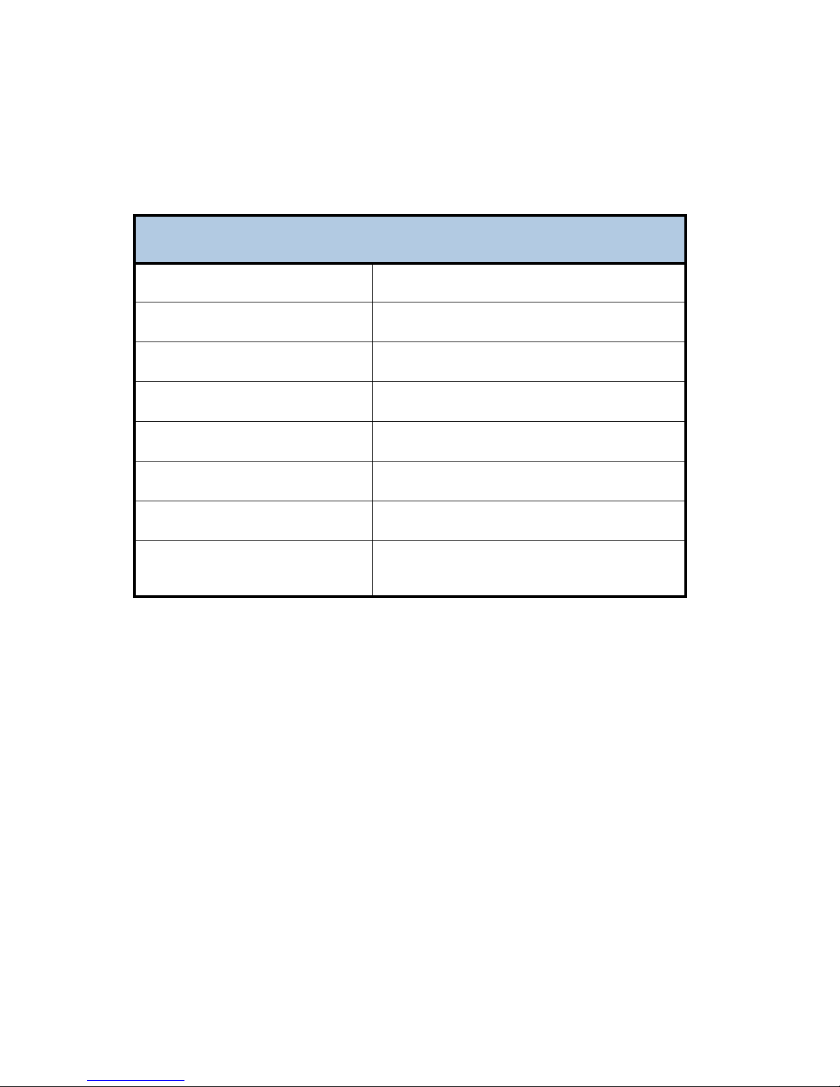
Physical Characteristics
iPump 562 Physical Characteristics
Physical Characteristics
Chassis Height
Chassis Width
Chassis Depth
Weight
Front/Rear Panel Labeling
Chassis Finish
Rear-panel silk-screen color
Front Panel
1 RU for desktop - 1RU using supplied rack ears
16.5 inches - with optional rack ears - 19 inches
11.5 inches
7.5 lbs.
Silver powder-coat, fine texture
Gray lettering per PMS-427C
Plastic snap-on bezel with 5 button switches
embedded in label
32 800092-02 Rev. C www.wegener.com
Page 33

Warranty
The following warranty applies to all WEGENER products:
All WEGENER products are warranted against defective materials and workmanship for a period of one
year after shipment to customer. Wegener Communications ' obligation under this warranty is limited
to rep airing or , at W egener Communications' option, replacing p arts, subassemblies, or entire
assemblies. Wegener Communications shall not be liable for any special, indirect, or consequential
damages. This warranty does not cover p arts or equipment, which have been subject to misuse,
negligence, or accident by the customer during use. All shipping cost s for warranty rep airs shall be
prepaid by the customer. There are no other warranties, express or implied, except as stated herein.
Technical Support
In the event that the unit fails to perform as described, contact Wegener Communications Customer Service at:
Corporate Office: Service Department:
WEGENER WEGENER
11350 Technology Circle
Customer Service
John's Creek 11350 Technology Circle
Duluth, GA 30097 Duluth, GA 30097
www.wegener.com 800092-02 Rev. C 33
 Loading...