

Page 1

TM
iPump Quick Start Guide
800009-02 Rev.B
Technology Park/Johns Creek
11350 Technology Circle
Duluth, GA 30097
Page 2

Data, drawings, and other material contained herein are proprietary to Wegener
Communications, Inc., and may not be reproduced or duplicated in any form
without the prior written permission of Wegener Communications, Inc.
The information contained herein is subject to change without notice. Revisions
may be issued to advise of such changes and/or additions.
Correspondence regarding this publication (800009-02 Rev.B) should be
forwarded to Wegener Communications, Inc. at Technology Park/Johns Creek,
11350 Technology Circle, Duluth, GA 30097-1502.
Phone 770-814-4000 Fax 770-497-0411
COMPEL
®
, MEDIAPLAN®, ENVOY, UNITY®, UNITY·IP and iPUMP are
trademarks of WEGENER Communications, Inc. All Rights Reserved.
All other trademarks are the property of their respective owners.
The Wegener iPump is approved under FCC Part 15B Class A, UL1950,
CSA, and CE.
800009-02 Rev.B
Page 3

iPump Quick Start Guide 1
Welcome to your iPump Media Server/Store
Welcome to your iPump Media Server/Store
Welcome to your iPump Media Server/StoreWelcome to your iPump Media Server/Store
and Forward
and Forward Receiver !
and Forward and Forward
advanced multimedia appliance that allows simple, efficient
management of both live and recorded digital video, audio, and data
content. With a single unit, you can receive, decode, and play out
broadcast-quality transmissions while receiving and recording
multiple programs or IP data files from a satellite or TCP/IP
connection. Along with our Compel MediaPlan
insert content into real-time or recorded programs and can schedule
playback of custom sequences of live and recorded content. This
Quick Start Guide will help you quickly set up and start operating
your iPump. For a full description of the iPump's abilities and
detailed installation and operation instructions, please consult the
iPump User's Reference Manual available on the worldwide web at
wegener.com. For additional help, contact us by phone at
(770) 814-4057, by fax at (678) 624-0294, or by email at
[email protected].
Receiver !
Receiver !Receiver !
Your Wegener iPump is an
®
software, you can
1111 Remove your
Remove your iPump
Remove your Remove your
accessories from the shipping carton. Call your shipping carrier
immediately if any damage is discovered.
2222 Place your iPump
Place your iPump
Place your iPumpPlace your iPump
or desktop or mount it in a standard equipment rack. If rackmounting your iPump, please consult the iPump User's
Reference Manual for detailed instructions and specific cautions.
iPump
iPumpiPump
, ac power cord, and bagged
indoors on a well-supported, flat table
800009-02 Rev.B
Page 4
2 iPump Quick Start Guide
3333 Connect
Connect
ConnectConnect
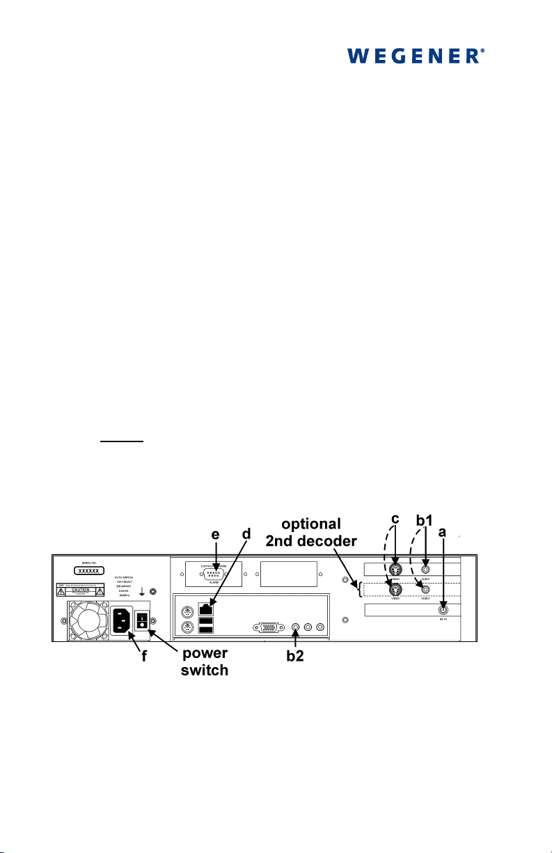
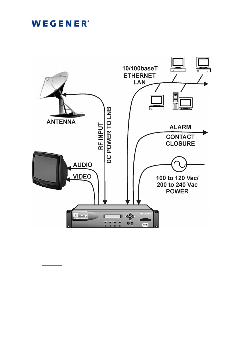
a) L-band output from your antenna's LNB to the iPump's RF
input port (
with extender cable attached or BNC connector if your unit
has the optional ASI input]
the following items (refer to Figures 1 and 2):
) [950 to 2150 MHz; female Type F connector
aaaa
b) a suitable monitor to the iPump's audio port (
optional, auxiliary audio port (
iPump User's Reference Manual for details.) [a 1/8-inch
stereo output jack is the connector for each audio port, but a
1/8-to-RCA adapter is included in the accessories bag]
c) your monitor to the iPump's video (
4-pin mini DIN (S-video) connector except in units with
optional decoders having a female, BNC connector. An
SVD-to-RCA adapter is included in the accessories bag.]
NOTE: Repeat steps b) & c) for the second decoder if
your iPump is equipped with two decoders.
d)
Your LAN line to the iPump's Ethernet port (
[10/100baseT; female RJ-45 connector]
) is also available. See the
b2
b2
b2b2
) port [
cccc
b1
b1
b1b1
is a female,
cccc
). (An
dddd
)
Figure 1. iPump Rear-panel Connectors
The Alarm port (e, Figure 1) on the rear panel may be used to
provide a contact closure during alarm conditions or on
command from Compel. See the iPump Reference Manual for
complete connector and signal details.
800009-02 Rev.B
Page 5
iPump Quick Start Guide 3
Figure 2. iPump Connections
NOTE
: Do not connect devices to the mouse, keyboard and
other connectors not described here. They are for factory use
only.
800009-02 Rev.B
Page 6

4 iPump Quick Start Guide
4444 Next, start your iPump
Next, start your iPump
Next, start your iPumpNext, start your iPump
as follows:
a) Connect the ac power cord to the iPump's IEC receptacle
(
, Figure 1) and to a 100-to-120 Vac or 200-to-240 Vac
ffff
source.
I
b) Set the power switch to the On position (
hold the Enter button (
ENTER
) on the front panel for two
) and press and
seconds. The iPump will power up and begin the boot
process. Outputs are muted during the short initialization
time. All eight LED indicators flash on and off as the unit
begins initialization. Until you configure your iPump's RF
settings (see Step
displayed (red
ALARM
), a loss-of-carrier alarm may be
6666
LED indicator is lit and LCD screen
indicates the alarm state). RF settings are not necessary for
units with the optional ASI input.
NOTE
normal shutdown (see Step
button (
User's Reference Manual for details). If the receiver is
tracking a carrier signal, the green
light.
800009-02 Rev.B
: To easily restart the iPump any time after a
), simply press the Enter
9999
ENTER
) on the iPump’s front panel (refer to the
CARRIER
LED will
Page 7
iPump Quick Start Guide 5
5555 Get to know
Get to know the iPump's front panel
Get to knowGet to know
the iPump's front panel
the iPump's front panel the iPump's front panel
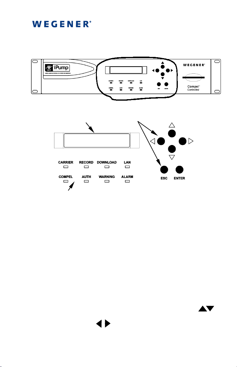
AREA ENLARGED BELOW
Liquid Crystal Display (LCD)
LED Indicators
Pushbuttons
Figure 3. iPump Front-panel Controls and Indicators
The liquid crystal display (LCD) provides menu, data, and input
screens to the user. Menu screens are entry points to further
screens showing signal or unit status or to user-input screens that
can be changed by the user. The "home" screen displays the
unit's serial number, E
, and alternately displays FEC ratio,
b/N0
signal frequency, and transport rate. This screen may be reached
at any time by repeatedly pressing the
ESC
button.
Six pushbuttons allow you to move through the various screens,
select characters for input, and accept or reject changes. To move
downward or upward through the menu screens, use the
and
the
buttons. To enter or change data in editable fields, press
ESC
ENTER
button and use the up and down arrow buttons ( )
to increment the highlighted character or digit. Use the right and
left arrow buttons ( ) to move to adjacent digits and press
ENTER
again to accept your input. Pressing
ESC
before
accepting your input will cancel any changes.
ENTER
800009-02 Rev.B
Page 8

6 iPump Quick Start Guide
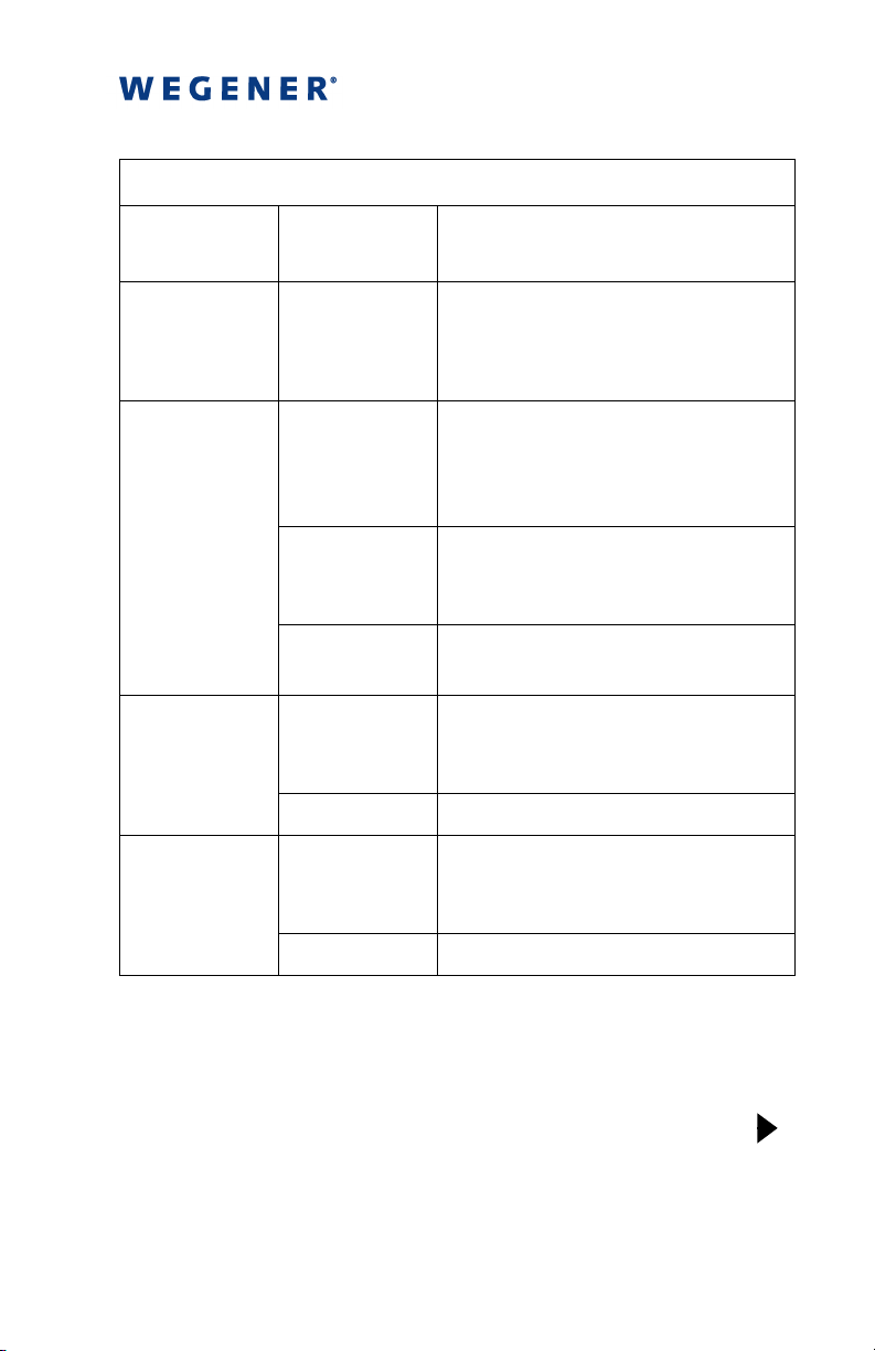
Eight light-emitting diodes (LEDs) illuminate to show unit status
at a glance. Table 1 gives the meaning of each LED indicator.
Table 1. LED Indicator Descriptions
Indicator
Label
CARRIER
RECORD
DOWNLOAD
LAN
COMPEL
Color and
State
GREEN
Receiver is tracking carrier.
Meaning
constant
GREEN
Receiver is not tracking carrier.
slow blink
GREEN
iPump is recording a program.
constant
Off iPump is not recording.
GREEN
constant
iPump is downloading a file via
Compel.
Off iPump is not downloading.
GREEN
constant
GREEN
slow blink
Light network activity over the
iPump's LAN interface.
Heavy network activity over the
iPump's LAN interface.
Off iPump observed no packet
transfers during the last 20 secs.
GREEN
constant
iPump has received a COMPEL
command within the last two
minutes.
GREEN
fast blink
iPump has been addressed by
COMPEL within the last five
seconds.
GREEN
slow blink
iPump is in tracking mode and
COMPEL is required but no
COMPEL command received
within the last two minutes.
800009-02 Rev.B
Page 9
iPump Quick Start Guide 7
Table 1 (continued). LED Indicator Descriptions
Indicator
Label
COMPEL
AUTH
WARNING*
ALARM*
Color and
State
Meaning
Off COMPEL is not required and not
received within the last two
minutes; or, iPump is not in
tracking mode.
GREEN
constant
Current transport stream is
protected by conditional access
(CA) and iPump is authorized and
descrambling.
GREEN
slow blink
Current transport stream is
protected by conditional access
(CA) but iPump is unauthorized.
Off Tracked channel is not scrambled
("in the clear").
AMBER
constant
One or more warning conditions
exist. Read warning information
from front-panel LCD.
Off No warning conditions exist.
RED
constant
One or more alarm conditions
exist. Read alarm message from
LCD.
Off No alarm condition exists
∗∗∗∗
Only one alarm or warning condition is displayed at a time
on the LCD. When multiple alarm or warning conditions
exist, those conditions are displayed in the order of
importance. The most critical condition is displayed first and
others may be viewed by pressing the right arrow button( ).
800009-02 Rev.B
Page 10
8 iPump Quick Start Guide
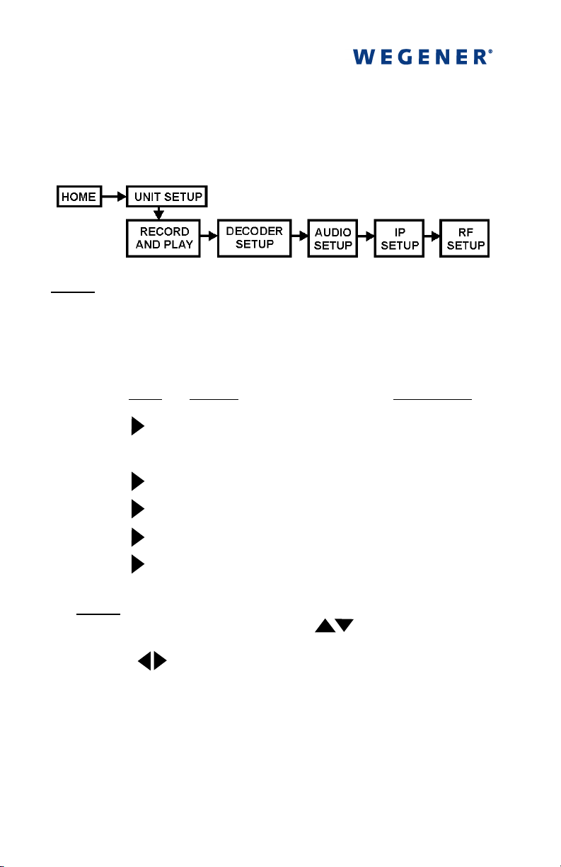
6666 Set up or adjust your iPump's RF settings
Set up or adjust your iPump's RF settings
Set up or adjust your iPump's RF settingsSet up or adjust your iPump's RF settings
at
the front panel. (If your unit has the optional ASI input, this step
is not necessary - go to step
). From the home screen, navigate
7777
to the RF Setup screen as follows:
NOTE: Use the arrow buttons to move left and right through
the menu screens and the
Use the
By pressing
button to move upward through the menu screens.
ESC
repeatedly, you can always return to the iPump
ESC
ENTER
button to move down a level.
home screen.
Press
a)
ENTER
b)
c)
d)
e)
f)
NOTE: To enter data in editable fields, press
Display Screen Type
UNIT SETUP
RECORD AND PLAY
DECODER SETUP
AUDIO SETUP
IP SETUP
RF SETUP
Menu
Menu
Menu
Menu
Menu
Menu
ENTER
and use
the up and down arrow buttons ( ) to increment the
highlighted character or digit. Use the right and left arrow
buttons ( ) to move to adjacent digits. Press
to accept your input or
to cancel changes.
ESC
ENTER
again
800009-02 Rev.B
Page 11
iPump Quick Start Guide 9
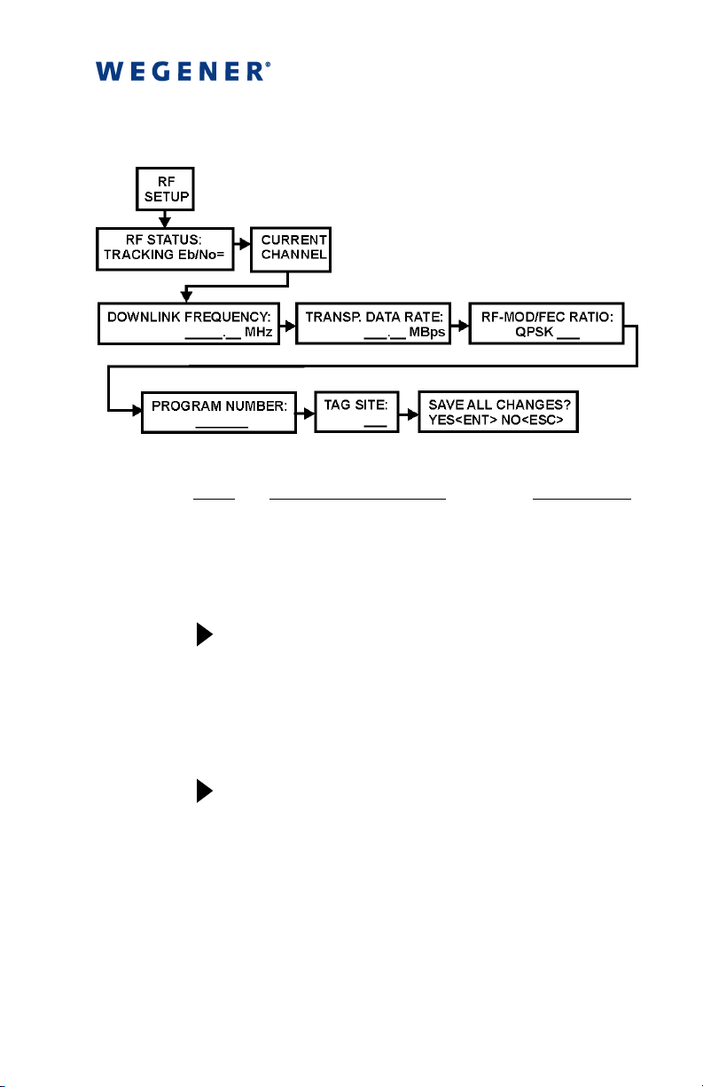
From RF Setup, adjust RF settings as follows:
g)
h)
i)
j)
Press
ENTER
ENTER
Display / Field Details Screen Type
RF STATUS:
TRACKING: Eb/No = XX.X
RF status is shown. If tracking,
then E
CURRENT CHANNEL
DOWNLINK FREQUENCY:
XXXXX.XX MHz
Enter downlink frequency from
the LNB local oscillator in
megahertz.
TRANSP. DATA RATE:
XXX.XX Mbps
Enter transport stream data
rate in megabits per second.
is also displayed.
b/N0
Data
Display
Menu
User Input Editable
User Input Editable
800009-02 Rev.B
Page 12
10 iPump Quick Start Guide
Press Display / Field Details Screen Type
k)
l)
m)
n)
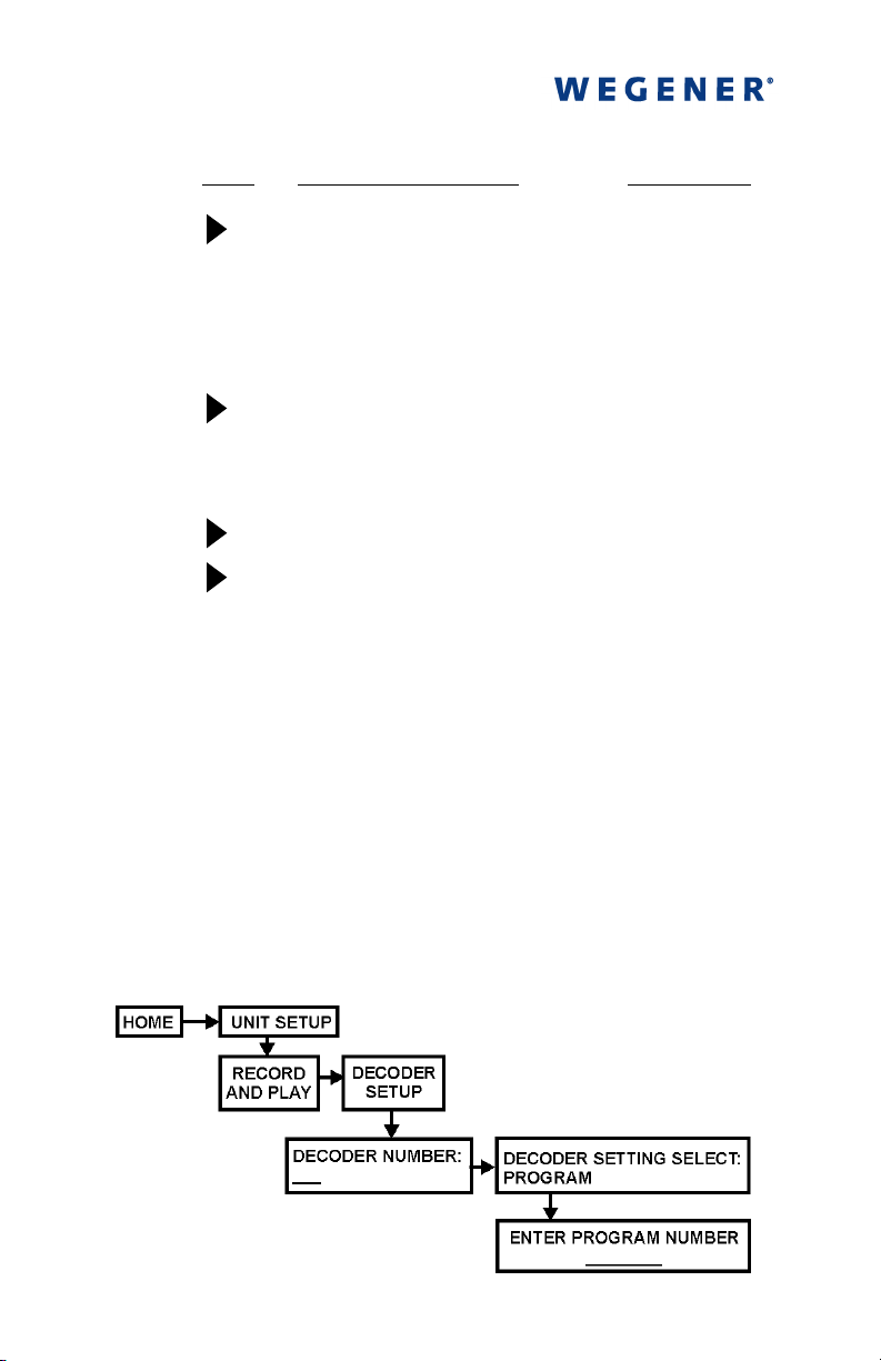
RF-MOD/FEC RATIO:
QPSK 3/4
RF modulation is QPSK.
Available forward error
correction ratios are 1/2, 2/3,
3/4, 5/6, and 7/8.
PROGRAM NUMBER:
00001
Number of program to select
from stream.
TAG SITE:
SAVE ALL CHANGES?
YES<ENT> NO<ESC>
ENTER
Press
to cancel all RF Setup changes.
to save or
ESC
If you are satisfied with all data entered, press
your changes. Pressing either
ENTER
or
ESC
User Input Selectable
User Input Editable
<Unused>
User Input Selectable
ENTER
to save
(which cancels all
changes) completes your RF setup and returns you to the Current
Channel screen. If all settings are correct and the red
ALARM
LED remains lit, there may be a problem with the antenna, its
position, or cable connections. Consult the iPump Reference
Manual for more troubleshooting help.
7777 To configure your iPump's decoder output,
To configure your iPump's decoder output,
To configure your iPump's decoder output,To configure your iPump's decoder output,
navigate from the Home screen to the Decoder Setup screen as
follows:
800009-02 Rev.B
Page 13

iPump Quick Start Guide 11
Press Display / Field Details Field Type
a)
ENTER
b)
c)
ENTER
d)
e)
If
PROGRAM
UNIT SETUP
RECORD AND PLAY
DECODER SETUP
DECODER NUMBER
1
Available decoders are 1 and 2.
If your iPump has only one
decoder, this Decoder
Number screen will not
appear. Instead, the Decoder
Setting Select screen
described in step e) will
appear.
DECODER SETTING SELECT:
FOLLOW TUNE
FOLLOW TUNE
program selection from the
current RF setup and sends
you back to the Decoder Setup
screen.
to select a particular program
from the stream.
the decoder.
is selected, go on to step f). Otherwise your
decoder setup is complete.
accepts the
PROGRAM
OFF
Menu
Menu
Menu
User Input Selectable
User Input Selectable
allows you
turns off
f)
ENTER
ENTER PROGRAM NUMBER:
001
Number of program to select
from stream. Available
program numbers are
dependent on transport
stream.
User Input Selectable
Your decoder setup is now complete. The selected program will
begin playing from the selected decoder.
800009-02 Rev.B
Page 14
12 iPump Quick Start Guide
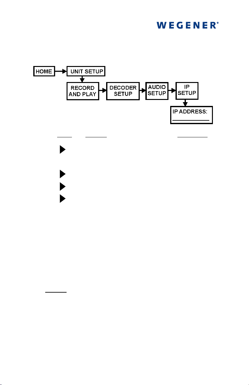
8888 For web browser control
For web browser control
For web browser controlFor web browser control
and status checking, first
navigate from the home screen to the IP Setup screen as follows:
Press
Press
a)
ENTER
b)
c)
d)
e)
ENTER
Display Field Type
UNIT SETUP
RECORD AND PLAY
DECODER SETUP
AUDIO SETUP
IP SETUP
Menu
Menu
Menu
Menu
Menu
and take note of the iPump's IP address displayed
on the screen. Then use the following steps to gain iPump
control from your web browser:
f) Using a computer on the LAN attached to your iPump,
open your web browser.
g) Type the IP address noted from the IP Address screen in
the browser's address box.
NOTE
: For IP addresses which include subfields with
leading zeros, you must omit those zeros when entering
the address in your browser. For example, IP address
128.092.056.004 would be entered as 128.92.56.4.
In some cases, it may be necessary to set specific values
for the IP and Subnet addresses. Consult your network
administrator.
800009-02 Rev.B
Page 15
iPump Quick Start Guide 13
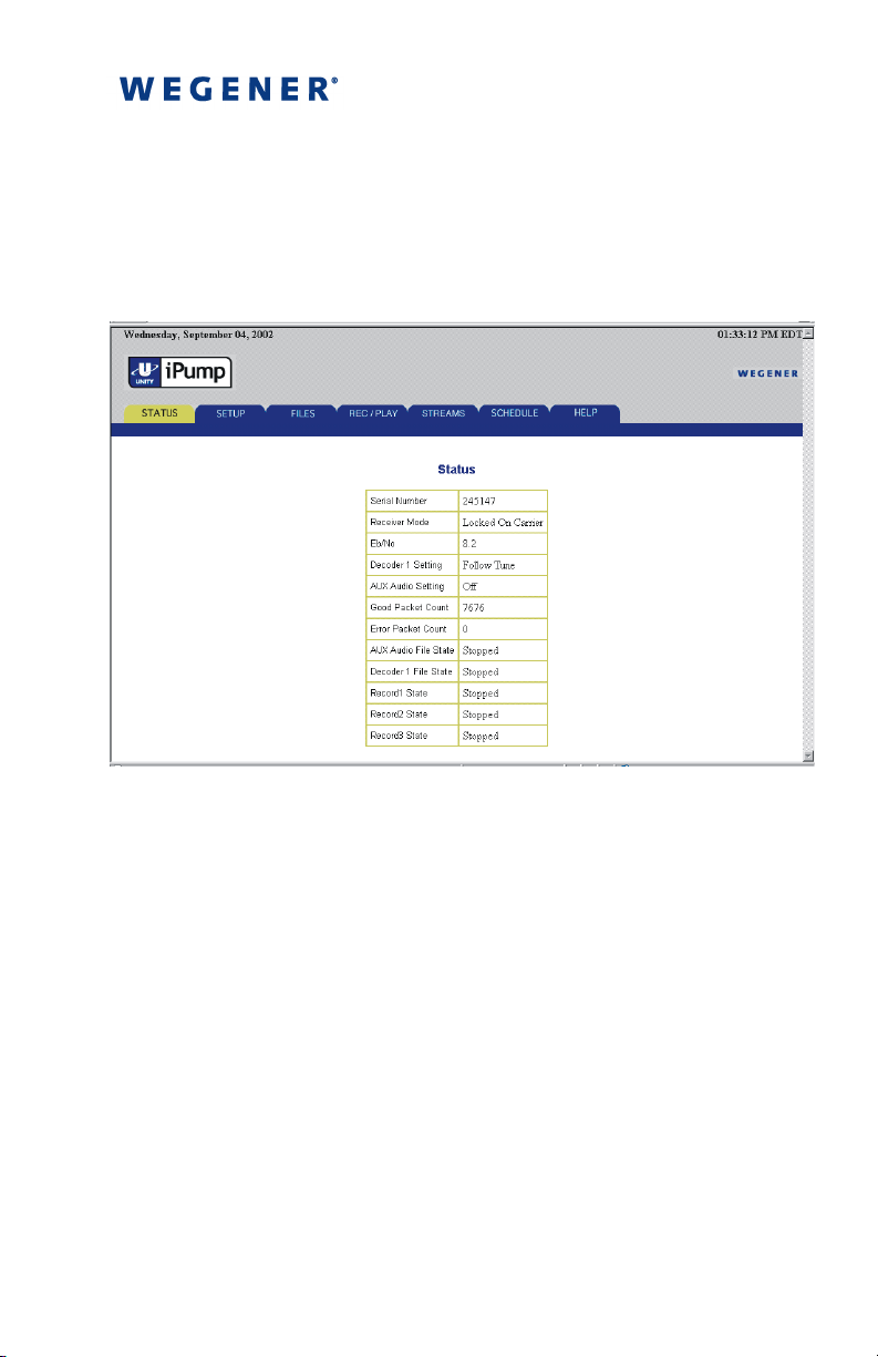
h) Press Enter (on the computer keyboard) and your
iPump's Status page will be displayed (Figure 4).
i) Click the appropriate tab to select Files, Schedule,
Status, Help, or Setup.
Figure 4. iPump Web Interface Status Page
800009-02 Rev.B
Page 16

14 iPump Quick Start Guide
9999 Shut down your iPump
Shut down your iPump
Shut down your iPumpShut down your iPump
from the front panel. Navigate
from the home screen to the Shutdown screen as follows:
a)
b)
c)
d)
e)
f)
Press
ENTER
ENTER
Display / Field Details Screen Type
UNIT SETUP
UNIT STATUS DETAIL
NAVIGATION HELP
UNIT SHUTDOWN
Are You Sure? !!!
No-ESC, Yes-ENTER
ESC
Press
ENTER
Please Wait…
UNIT SHUTTING DOWN!
to cancel or
to shut down.
Menu
Menu
Menu
Menu
User Input Selectable
Status
Display
At shutdown, the LCD screen becomes blank and the LED indicators
go out. Your iPump is now shut down. The power switch on the rear
panel may be left in the on position for quick restart from the front
panel (see note in Step
).
4444
800009-02 Rev.B
 Loading...