

Page 1

WEGENER i6420 DIGITAL AUDIO SERVER
QUICKSTART INSTALLATION INSTRUCTIONS
This satellite receiver has been provided for the
reception of Atlanta Falcons NFL. Once installed,
please contact network support for activation and
programming.
INTRODUCTION
This Quick Start guide provides direction on how to quickly set up and start
operating the i6420 professional media server in order to receive WestwoodOne
programming. For complete information please go to:
www.dg-tech.net
Please expedite the installation of this receiver as it must be installed and online
no later than four weeks from the original ship date.
To activate this receiver, please contact WestwoodOne Network Operations
Support between 8AM and 10PM ET, Monday through Friday at (888) 435-7450;
option 1, then option 2. Our operators are available to assist with:
Installation Questions
Authorization of the receiver after installation.
Page 1 of 7
Version 2.0 01/31/14
Page 2

INSTALLATION INSTRUCTIONS
1) This receiver should be installed in a location that maintains a consistent
temperate of 65-75 degrees with ample ventilation to the front, sides and rear
of the receiver.
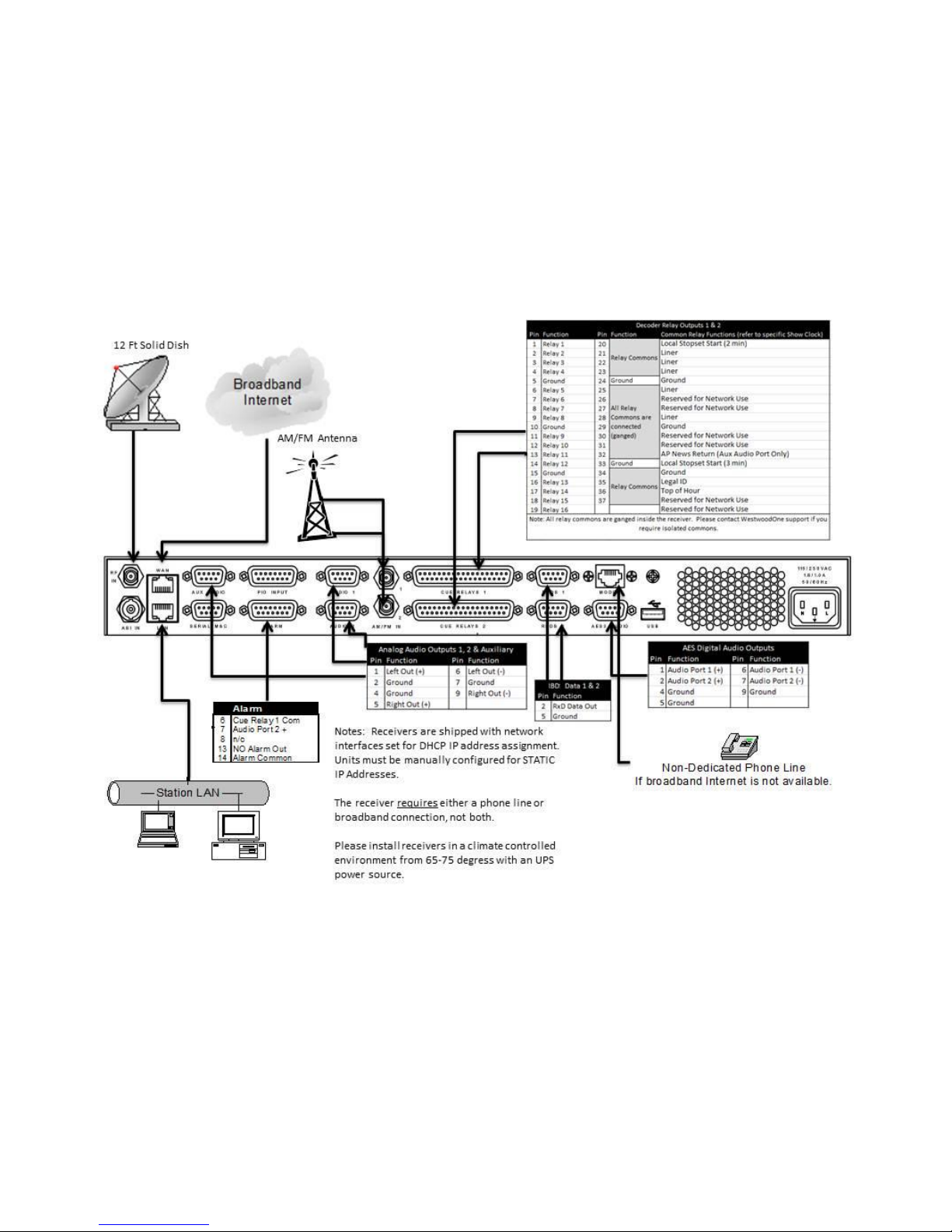
2) Connect your RG-6 cable from your satellite dish to the RF input on the back
of the receiver. If more than one receiver is to be connected, a professional
grade splitter with a DC power pass port is recommended.
a. Note: In a multi-receiver installation, it is recommended to use a
professional power inserter and not to power your LNB from the
Wegener receiver.
3) Connect your stations broadband network (internet) to the receiver at the LAN
port if your network is behind a firewall (common) or the WAN port if outside a
firewall (uncommon).
a. Note: A reliable network connection is required to maintain a network
“return path” communication with our network in order to ensure
proper functionality of the receiver. This is an outbound
communication only and must be maintained at all times. Because of
this requirement, we are unable to authorize receivers that are not
connected with this “return path”. If your station does not have public
internet access, please contact Network Operations for assistance.
4) Connect the in-house AM or FM signal antenna or an independent AM/FM
antenna to the port(s) corresponding with the programs identified on page 1.
a. Note: This is a required connection and must be maintained at all
times.
5) Connect your DB9 audio and DB37 relay connectors to the ports
corresponding with the programs identified on page 1.
6) Plug the receiver into a reliable, stable and properly grounded power source.
a. Note: Wegener and WestwoodOne strongly recommend that you use
an Uninterruptible Power Supply (UPS) with power line filtering to
prevent damage to the unit during electrical storms or power surges.
Please be aware that electrical damage caused by lightning or power
surges is not covered under the warranty. RF surge filtering is also
strongly recommended for this reason.
7) Verify your dish alignment and signal strength by looking at the EbNo and RF
levels. EbNo must be at least 9.0 and RF between 20-60 in order to
authorize the receiver.
a. Note: A distribution amplifier is not recommended for main cable runs
less than 250 ft. If amplification is necessary to attain minimum specs,
a line amp ahead of the splitter yields more favorable results.
b. Note: Line attenuators to drop RF to within maximum RF levels should
be used sparingly to avoid unnecessary noise injection.
8) Once all connections are made, and levels meet minimum specifications,
please contact WestwoodOne Network Operations for authorization.
Page 2 of 7
Version 2.0 01/31/14
Page 3
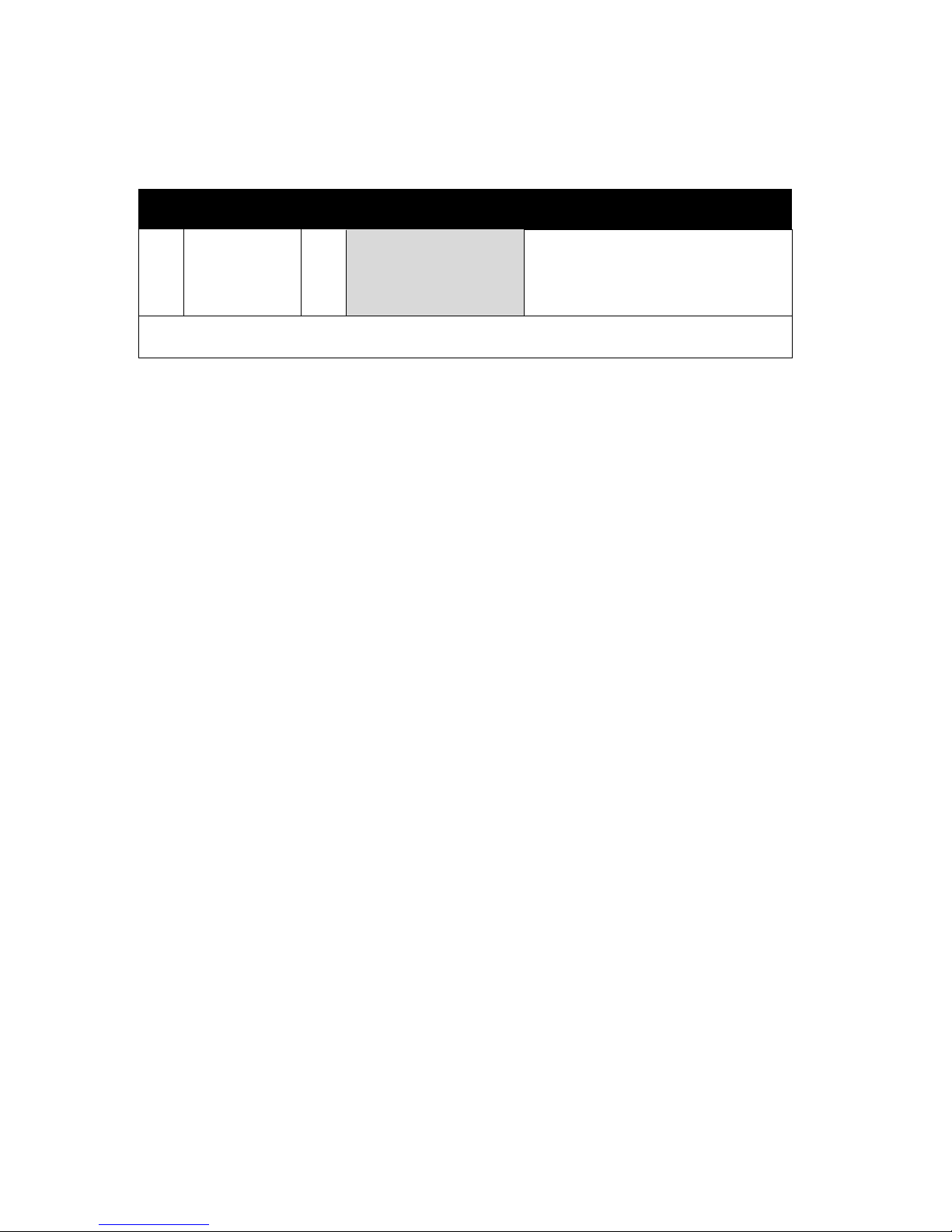
Atlanta Falcons NFL Programming
Atlanta Falcons NFL Relays
Pin
Function
Pin
Function
Relay Functions
1
Relay 1
20
Relay Commons
Local Stopset Start
2
Relay 2
21
Liner / ID
3
Relay 3
22
End of Game
4
Relay 4
23
Not Used
Note: All relay commons are ganged inside the receiver. Please contact WestwoodOne support if
you require isolated commons.
Page 3 of 7
Version 2.0 01/31/14
Page 4
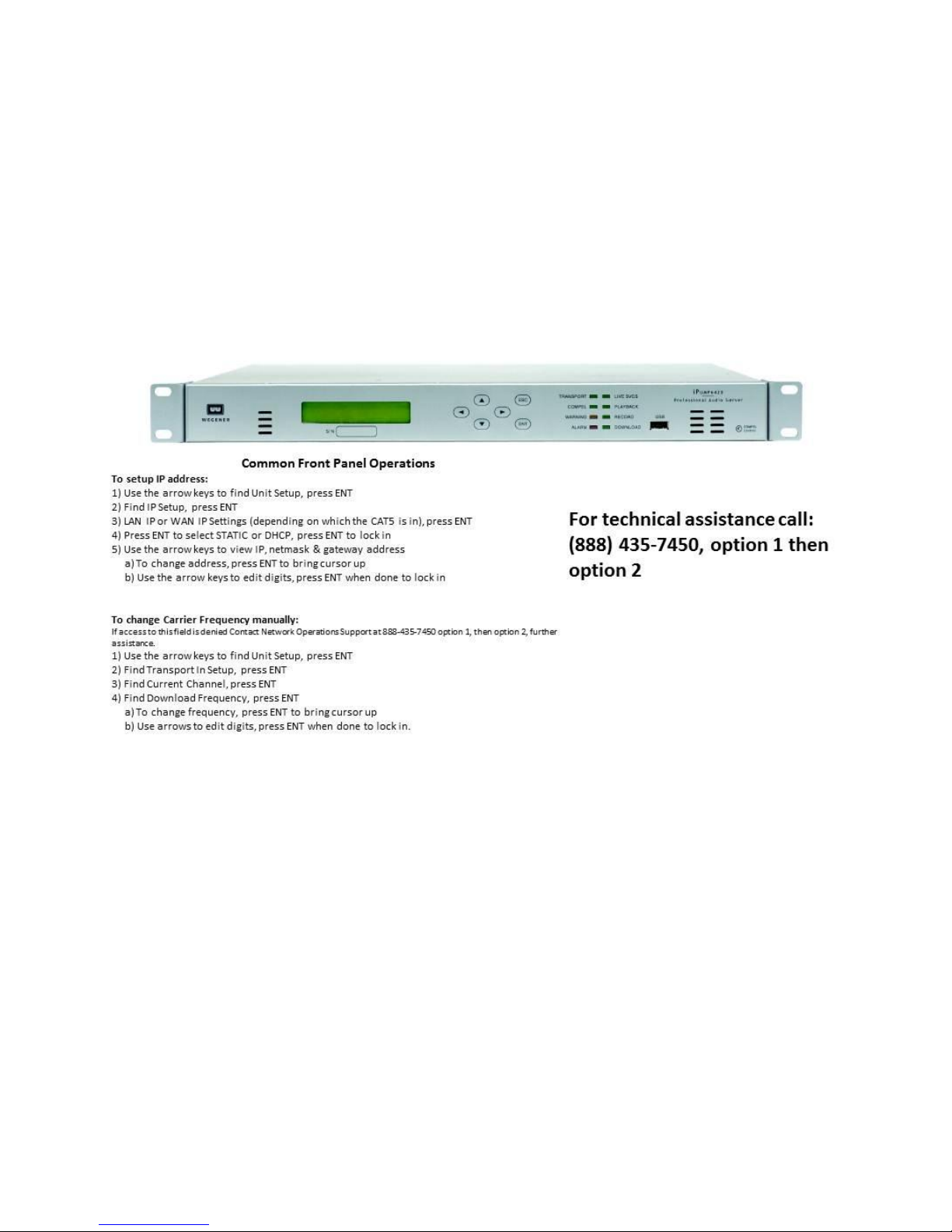
Version 2.0 01/31/14
Page 4 of 7
Page 5
Version 2.0 01/31/14
Page 5 of 7
Page 6
Safety Summary
The iPump 6420 is designed for safe use with few special precautions required of the user. The
following items are basic precautions to use when installing and working with the iPump 6420:
Do not open the iPump 6420's chassis cover as this will void the limited product warranty.
Location and Mounting
The iPump i6420 should be mounted in a standard 19-inch equipment rack. After
mounting, maintain a clean, dry environment for the unit.
Precautions
WARNING
This is a Class A product. In a domestic environment this product may cause radio
interference for which the user may need to take mitigating action.
DANGER
To avoid damage to this and other equipment, or personal injury, the following items should be
strictly observed.
Elevated Operating Ambient
When equipment is installed in a closed or multi-unit rack assembly, the operating ambient
temperature of the rack environment may be greater than the room ambient temperature.
Therefore, consideration should be given to the ambient air temperature within the rack, and not
just inside the room, when deciding if the maximum recommended ambient operating
temperature (TMRA) is being met.
Reduced Air Flow
Equipment should be installed such that airflow required for safe operation of the equipment is
not compromised. Units may be stacked with other rack-mount equipment without gaps.
However, to ensure adequate air flow, leave rear and front vents unobstructed. Providing1/2 inch
clearance for the right side air vents results in a longer product life for the iPump 6420.
Mechanical Loading
Mounting of the equipment in a rack should be such that a hazardous condition is not produced
by uneven loading. This unit is not very heavy, but total rack loading must be considered. Also, do
not rest any unsupported equipment on the iPump 6420.
Circuit Overloading
Consideration should be given to the connection of the equipment to the supply circuit and the
effect that overloading of circuits could have on over-current protection and supply wiring. Ensure
that the total rack or breaker power consumption does not exceed the limits of the ac branch
circuit. Appropriate consideration of equipment ratings should be used when addressing this
concern.
Version 2.0 01/31/14
Page 6 of 7
Page 7

DANGER
Reliable Earthing
Reliable earthing of rack-mounted equipment should be maintained. Particular attention should
be given to supply connections other than direct connections to the branch circuit (use of power
strips, chassis ground lugs, etc.).
Lithium Battery
Proper disposal and replacement of the motherboard’s lithium battery is necessary. Replacing the
battery with an incorrect type presents the risk of explosion. Dispose of used batteries according
to the package instructions.
Telecommunication Line Cord
To reduce the risk of fire, use only No. 26 AWG or larger telecommunication line cord.
Rack Installation Procedure
The iPump i6420 is sized at 1 RU and will fit an EIA-standard, 19-inch-wide equipment rack.
1) Install angle brackets or cross-supports capable of supporting both the unit and its
connecting cables. Screw or bolt the supports securely to the equipment rack.
2) Place the iPump 6420 on its supports and use four anchor screws or bolts and nuts to
secure the unit's front brackets to the rack.
WARNING
Do not block any of the ventilation or fan opening on the front, side, or rear of the unit. Support
arrangements that do not allow adequate air flow or that block the openings on front, side and
rear vents may result in overheating and damage to the iPump 6420.
WARNING
The front brackets must be secured to the rack. If front brackets are left unsecured, the unit may
shift forward and fall from the rack during installation or operation. Failure to secure the front
brackets may result in personal injury and/or damage to the equipment.
WARNING
Locate the iPump 6420 and its cables to avoid impacts, spills, and pulling cables and to ensure
sufficient air flow. Failure to locate the iPump 6420 in a proper environment may result in damage
to the equipment.
Page 7 of 7
Version 2.0 01/31/14
 Loading...