

Page 1

Installation Guide
Model DVR395/DVR396
DIGITAL VIDEO RECEIVER
Data, drawings, and other material
contained herein are proprietary to
Wegener Communications, Inc., and may
not be reproduced or duplicated in any form
without the prior permission of Wegener
Communications, Inc.
When ordering parts from Wegener
Communications, Inc., be sure to include
the equipment model number, equipment
serial number, and a description of the part.
In all correspondence with Wegener
Communications, Inc., regarding this
publication, please refer to
DVR395/DVR396-002E.
First Edition: July 1997
Revised: December 2000
WEGENER
COMMUNICATIONS
TECHNOLOGY PARK/JOHNS CREEK
11350 TECHNOLOGY CIRCLE
DULUTH, GEORGIA 30097-1502
(770) 814-4000 FAX (770) 623-0698
R
Page 2

Page 2
This Page Intentionally Left Blank
DVR395/DVR396-002 Page 2 of 30
Page 3
Page 3
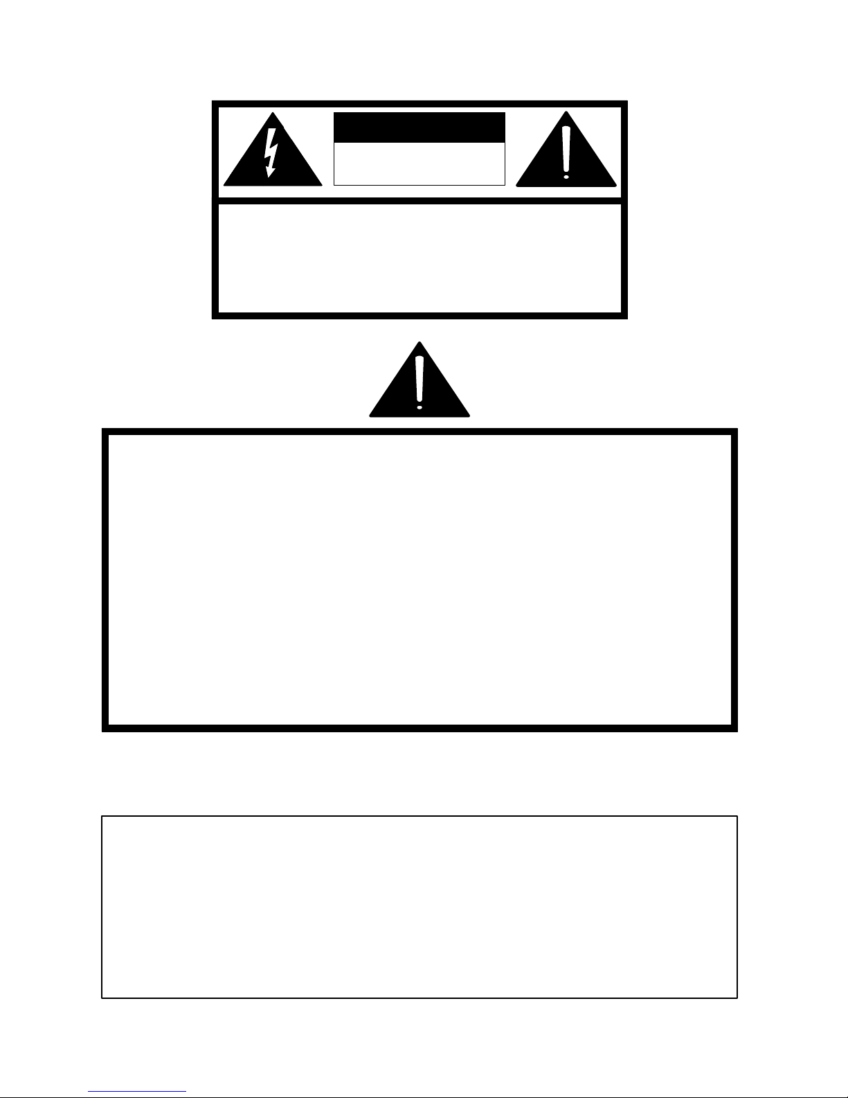
CAUTION
RISK OF ELECTRIC
SHOCK
DO NOT OPEN
CAUTION: TO REDUCE THE RISK OF ELECTRIC SHOCK,
DO NOT REMOVE COVER (OR BACK).
NO USER-SERVICEABLE PARTS INSIDE.
REFER SERVICING TO QUALIFIED SERVICE PERSONNEL.
CAUTION
As this unit is intended to interface with other electrical/electronic systems,
proper engineering practices must be adhered to during installation and checkout.
All AC power and ground must be installed in accordance with National Electric
Code Standards as to conductor size and limitations (see NFPA 70, articles 200280, as amended, if required), and lightning protection must be provided.
All RF interconnections must be properly shielded to prevent ingression or
egression of potential interfering sources to existing services.
Any damage to this unit caused by improper wiring/interconnections will void any
warranty extended.
WARRANTY
The following warranty applies to all Wegener Communications products.
All Wegener Communications products are warranted against defective materials and workmanship
for a period of one year after shipment to customer. Wegener Communications' obligation under this
warranty is limited to repairing or, at Wegener Communications' option, replacing parts,
subassemblies, or entire assemblies. Wegener Communications shall not be liable for any special,
indirect, or consequential damages. This warranty does not cover parts or equipment which have
been subject to misuse, negligence, or accident by the customer during use. All shipping costs for
warranty repairs will be prepaid by the customer. There are no other warranties, express or implied,
except as stated herein.
Page 3 of 30 DVR395/DVR396-002
Page 4

Page 4
This Page Intentionally Left Blank
DVR395/DVR396-002 Page 4 of 30
Page 5

Page 5
ABOUT THIS MANUAL
This manual was composed in Microsoft Word 97, and is configured to be used most easily as an
electronic document. It can be printed and used as a hard copy, but some features, such as links,
are not accessible in that mode.
If viewing the electronic version, we recommend you safeguard the original to avoid the effects
of somehow altering your master copy.
1. Cross-references
Cross-references are internally linked for easy access. If you are viewing the electronic version
of this manual, and see text that is blue and underlined, such as (TABLE OF CONTENTS) you
can “click” your mouse on that text and “link” to that section.
When you are ready to return to the previous section, “click” on the web toolbar “back” arrow
and return. The web toolbar should appear automatically when you use a link, but if it does not
you can invoke it from Toolbars on the View menu.
Because many users will print the manual, we have also included the page numbers for most
links.
2. Table of Contents
You can also link from the Table of Contents to any listed page. This also applies to the List of
Tables and List of Illustrations. Just “click” on the page number for any section, table, etc., you
want to move to. Return to the Table of Contents as in Number 1 above.
3. Other Viewing Methods
In the electronic Word version, there are several methods of moving about a document.
“Clicking” Document Map or Online Layout on the View menu will open a window showing the
document outline. This is similar to the Table of Contents, and will allow you to move about the
document by “clicking” on a section. It has the advantage of not going away when you move to
another section. It also has the disadvantage of taking up screen space when it is open.
Another way to better view the document is to “click” on the “Up arrow” icon on the Web
Toolbar. This will minimize many of the toolbars, freeing most of the screen for viewing the
manual. “Click” the arrow again to restore the toolbars.
4. Wegener Communications, Inc. Web Site.
This manual and others may be accessed on the Wegener Communications Web Site at
http://www.wegener.com/
and read, print, or download it.
. Once on the site, go to the appropriate product, access the manual,
Page 5 of 30 DVR395/DVR396-002
Page 6

Page 6
This Page Intentionally Left Blank
DVR395/DVR396-002 Page 6 of 30
Page 7

Page 7
TABLE OF CONTENTS
ABOUT THIS MANUAL............................................................................................................. 5
TABLE OF CONTENTS ............................................................................................................. 7
LIST OF ILLUSTRATIONS....................................................................................................... 8
LIST OF TABLES ........................................................................................................................ 8
SECTION 1 GENERAL INFORMATION ................................................................... 9
1.1 INTRODUCTION............................................................................................................. 9
1.2 UNPACKING AND INSPECTION ................................................................................ 9
1.3 PHYSICAL ENVIRONMENT ........................................................................................ 9
1.3.1 DVR395 DESKTOP VERSION ....................................................................................... 9
1.3.2 DVR395 RACK-MOUNTING VERSION ......................................................................... 9
1.3.3 ELEVATED OPERATING AMBIENT .............................................................................. 10
1.3.4 REDUCED AIR FLOW .................................................................................................. 10
1.3.5 MECHANICAL LOADING ............................................................................................. 10
1.3.6 CIRCUIT OVERLOADING ............................................................................................. 10
1.3.7 RELIABLE EARTHING ................................................................................................. 10
1.4 REAR PANEL CONNECTIONS.................................................................................. 11
1.4.1 FERRITE CORES AND THEIR INSTALLATION............................................................... 11
1.4.1.1 Types Of Ferrites .............................................................................................................. 11
1.4.1.2 Ferrite Installation.............................................................................................................12
1.5 SECURITY LABELS ..................................................................................................... 14
1.6 TECHNICAL SUPPORT............................................................................................... 16
1.7 MANUALS ...................................................................................................................... 16
SECTION 2 POWER ON PROCEDURES................................................................ 17
2.1 GENERAL....................................................................................................................... 17
2.2 CONTROL DIP SWITCHES ........................................................................................ 17
2.3 FRONT PANEL CONTROLS AND INDICATORS .................................................. 17
2.4 LED & ALARM/WARNING CONDITIONS.............................................................. 19
2.5 POWER ON PROCEDURE .......................................................................................... 21
SECTION 3 SETUP....................................................................................................... 23
3.1 GENERAL....................................................................................................................... 23
3.2 ON SCREEN DISPLAY (OSD)..................................................................................... 23
3.3 CUSTOMIZING SETTINGS FOR YOUR SYSTEM................................................. 24
APPENDIX A RMA REQUEST FORM .................................................................... 27
RECORD OF REVISIONS........................................................................................................ 29
SERVICE RETURN ADDRESS ............................................................................................... 30
Page 7 of 30 DVR395/DVR396-002
Page 8

Page 8
LIST OF ILLUSTRATIONS
Figure 1. Ferrite Bead Installation For DVR396 ......................................................................... 11
Figure 2. DVR395 Rear Panel ..................................................................................................... 13
Figure 3. DVR396 Rear Panel ..................................................................................................... 13
Figure 4. DVR395 Front Panel .................................................................................................... 18
Figure 5. DVR396 Front Panel .................................................................................................... 18
Figure 6. Welcome Banner .......................................................................................................... 21
Figure 7. Failure Banner .............................................................................................................. 21
LIST OF TABLES
Table 1. Equipment Specifications .............................................................................................. 10
Table 2. DVR395/DVR396 Interconnect Descriptions .............................................................. 14
Table 3. DVR395 Serial Cables To Terminal or Printer ............................................................. 15
Table 4. Control DIP Switch Functions....................................................................................... 17
Table 5. Front Panel Controls and Indicator................................................................................ 19
Table 6. LED Indications............................................................................................................. 20
Table 7. SELECT And ENTER Key Functions........................................................................... 23
LIST OF CAUTIONS & WARNINGS
Warning Radio Interference ................................................................................................... 9
Caution F Connector Loading ............................................................................................... 14
Caution RJ-12 Connection .................................................................................................... 15
DVR395/DVR396-002 Page 8 of 30
Page 9
Page 9
SECTION 1
GENERAL INFORMATION
1.1 INTRODUCTION
This section contains instructions for connecting the Model DVR395/DVR396 Digital Video
Receiver into a satellite receive system, and operating it in that mode.
1.2 UNPACKING AND INSPECTION
Carefully unpack the unit and inspect it for obvious signs of physical damage, which might have
occurred during shipment. Any damage claims must be reported to the carrier immediately. Be
sure to check packing materials carefully for important documents and materials. Please contact
Wegener Communications Customer Service Department with questions at (770) 814-4057 or
fax (770) 232-0621. See Section 1.6 (Page 16) for more Technical Support assistance.
This is a Class A product. In a domestic environment this product may cause radio
interference, in which case the user may be required to take adequate measures.
* * * WARNING * * *
1.3 PHYSICAL ENVIRONMENT
To avoid damage to this and other equipment, or personal injury, the following items should be
strictly observed.
1.3.1 DVR395 Desktop Version
The DVR395 Receiver may be installed on any reasonably level surface located in a clean, dry
environment. Avoid locations subject to severe vibration or jarring impacts. The unit will meet
the full 10 to 40
Set it on a hard surface so that the mounting feet can maintain clearance under the unit. Avoid
stacking objects or equipment against or on top of the unit where the vent holes would be
blocked.
1.3.2 DVR395 Rack-Mounting Version
o
C operating temperature specification only if adequate ventilation is provided.
Mount the DVR395 Receiver in a standard EIA 19-inch (48.3 Cm) equipment rack located in a
clean, dry environment. Attach the front mounting ears at all four mounting points and do not
stack any other equipment on the receiver. Check that the total rack current consumption is
within the limits of the AC branch circuit and that a reliable earth safety ground is maintained.
The unit will meet the full 10 to 40
ventilation is provided. This requirement is easily met if the installer leaves one empty 1-3/4inch (4.4 Cm) rack-unit space between units (50% rack utilization). Forced air is usually not
Page 9 of 30 DVR395/DVR396-002
o
C operating temperature specification only if adequate
Page 10
Page 10
required if the room is cool (<75°F). For higher rack mounting densities, forced-air rack
ventilation is strongly recommended. Please note the average per-unit power dissipation of 45
watts (@ max LNB DC current loading) and plan accordingly.
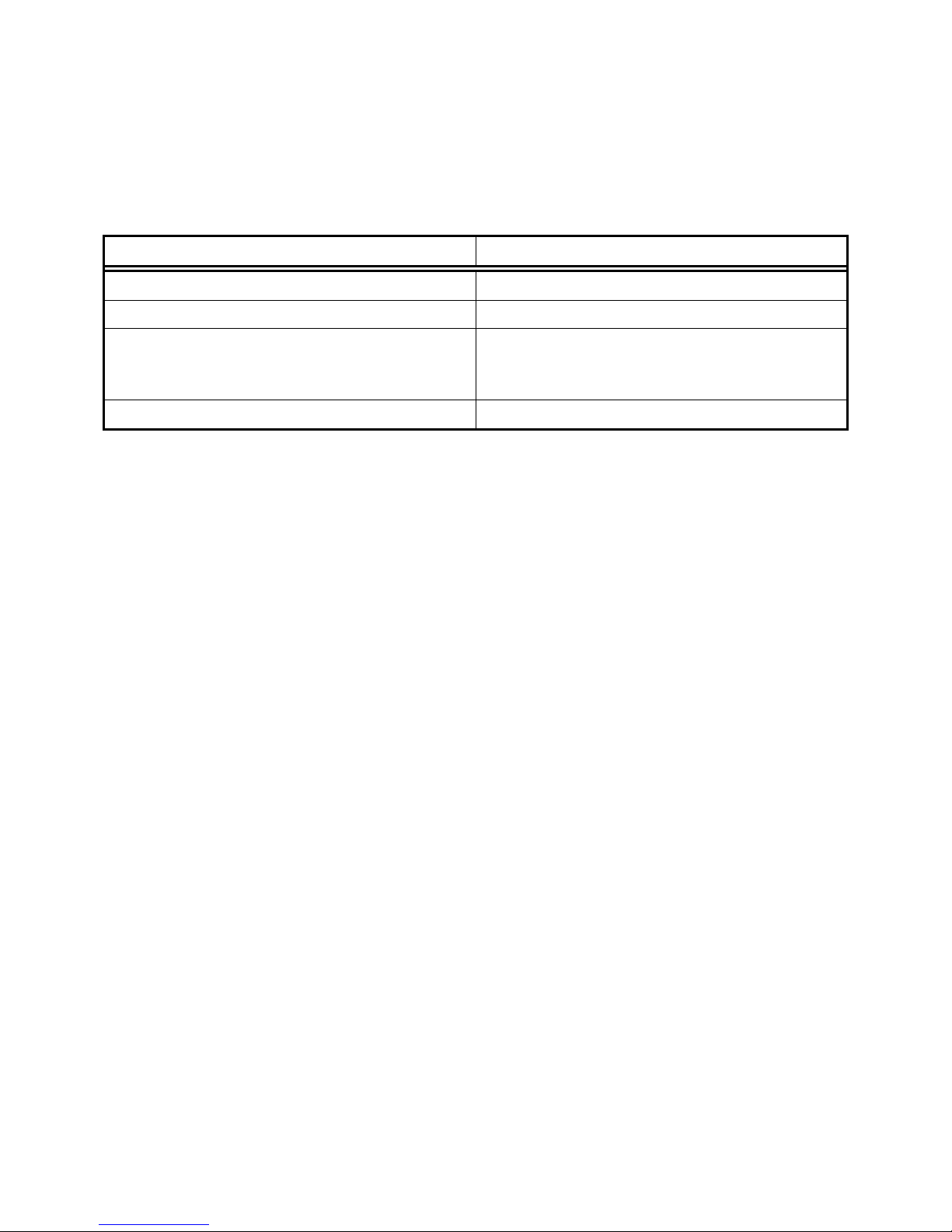
Table 1. Equipment Specifications
Parameter Specification
Input Rating 115/230 VAC, 0.8/0.5A, 50/60Hz
Operating Temperature Range 5° - 40° C
Operating Humidity Maximum relative humidity 80% for
temperatures up to 31° C, decreasing linearly
to 50% relative humidity at 40° C.
Maximum Operating Elevation 6560 Ft (2000M) above sea level
1.3.3 Elevated Operating Ambient
If equipment is installed in a closed or multi-unit rack assembly, the operating ambient of the
rack may be greater than the room ambient. Therefore, considerations should be given to the
TMRA, or Temperature inside the Mounting Rack, and not just inside the room.
1.3.4 Reduced Air Flow
Installation of the equipment in a rack should be such that the amount of airflow required for safe
operation of the equipment is not compromised.
1.3.5 Mechanical Loading
Mounting of equipment in a rack should be such that a hazardous condition is not achieved due
to uneven loading
1.3.6 Circuit Overloading
Consideration should be given to connection of the equipment to the supply circuit and the effect
that overloading of circuits could have on overcurrent protection and supply wiring. Appropriate
consideration of equipment nameplate ratings should be used when addressing this concern.
1.3.7 Reliable Earthing
Reliable earthing of rack-mounted equipment should be maintained. Particular attention should
be given to supply connections other than direct connection to the Branch (use of power strips).
DVR395/DVR396-002 Page 10 of 30
Page 11
Page 11
1.4 REAR PANEL CONNECTIONS
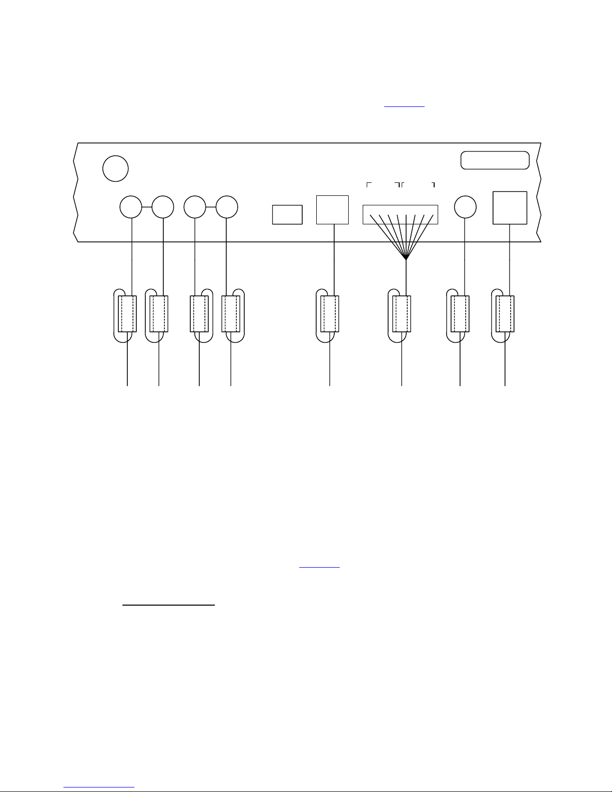
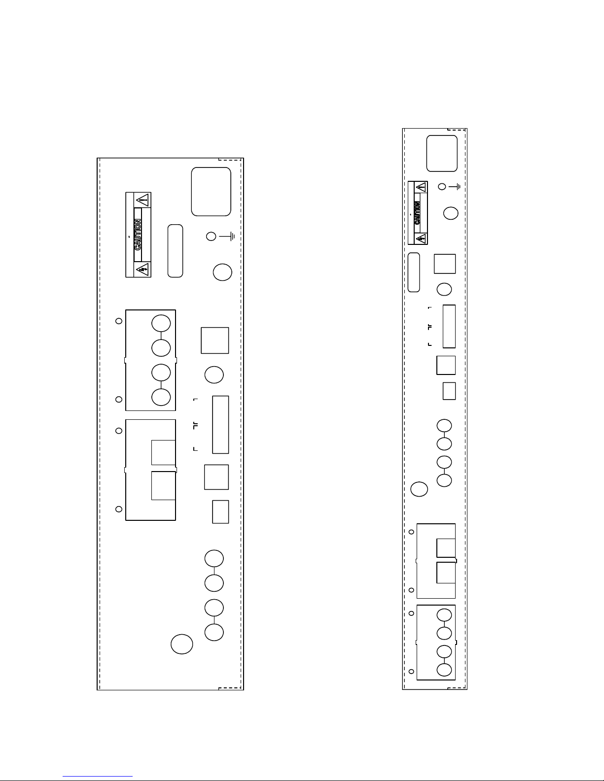
The DVR395 rear panel connections are shown and described in Figure 2 (Page13).
RF IN
R
AUDIO
2
AUDIO
1
MODE
L
R
L
SERIAL
PORT
16
CONTACT RATING 0.1A @ 30VDC
ALARM
COM
N/O
Figure 1. Ferrite Bead Installation For DVR396
GND
CLOSURE
1
N/C
+
S/N
VIDEO
2
+
-
-
OUT OUT
S-VIDEO
1.4.1 Ferrite Cores And Their Installation
In order to meet FCC requirements for Radiated Emissions, this unit must have Ferrites installed
on certain cables. Failure to install these cores may allow interference with other equipment,
resulting in degraded audio and/or video signals. Eight ferrite cores have been shipped with the
unit, and should be installed per the following instructions.
As a basic rule, all cables or wires to any one connector are looped through one ferrite. This is
particularly important to the relay outputs (See Figure 1
1.4.1.1 Types Of Ferrites
(Page 11).
There are two different types of ferrites included with the unit – three large and 5 smaller ones.
Both types are made to clamp on a loop of the cable(s) and minimize electronic signals being
radiated from the cable.
This is necessary because cables carrying electronic signals often act as broadcast antenna,
sending “Radio” signals to other cables, which can “Receive” them and inject them into other
units’ signals, causing interference with the other signals. To reduce this as much as possible, all
Page 11 of 30 DVR395/DVR396-002
Page 12

Page 12
installations, but especially in multi-service environments, should use high-quality shielded
cables, with the shield grounded according to good engineering standards.
1.4.1.2 Ferrite Installation
For this installation, there are three ferrites that are larger than the others. These should be used
for the cables numbered 6, 7, and 8 in the list below. These are the relay cables, the video cable,
and the S-Video cable. The other five cables will normally have a smaller total diameter, and
should fit into the smaller ferrites.
These ferrites must be installed on cables attached to the following connectors:
Connector
Ferrite Size
1. Audio 1 Left Small
2. Audio 1 Right Small
3. Audio 2 Left Small
4. Audio 2 Right Small
5. Serial Port Small
6. Alarm and Closure Relays. Large
One ferrite for all wires to relays.
7. Video Large
8. S-Video Large
The cables must pass through the ferrite and then loop around and pass through again. See
Figure 1
(Page 11). For proper results, the core should be positioned on the cable as close to the
chassis connector as possible. With minimal slack in the loop, the wiring alone should properly
support the core. No additional support should be necessary.
DVR395/DVR396-002 Page 12 of 30
Page 13
Page 13
Figure 2. DVR395 Rear Panel Figure 3. DVR396 Rear Panel
50/60Hz
0.6/0.3A
115/230VAC
50/60Hz
0.6/0.3A
115/230VAC
DO NOT OPEN
CH 2/3 MOD
RISK OF ELECTRIC SHOCK
RISQUE DE CHOC ELECTRIQUE NE PAS OUVRIR
DO NOT OPEN
RISK OF ELECTRIC SHOCK
RISQUE DE CHOC ELECTRIQUE NE PAS OUVRIR
AVIS:
3
5
AUDIO
S/N
CH 2/3 MOD
S-VIDEO
AVIS:
S-VIDEO
OUT OUT
VIDEO
S/N
-
2
+
-
1
+
CLOSURE
N/C
GND
COM
ALARM
N/O
CONTACT RATING 0.1A @ 30VDC
MODULE 2
AUDIO
MODULE 1
(MODULE 2)
(MODULE 1)
6
4
RS232
HSD OUT
RF IN
VIDEO
CLOSURE
ALARM
PORT
SERIAL
AUDIO
2 1
AUDIO
OUT OUT
-
+
2
-
+
1
N/C
GND
COM
N/O
CONTACT RATING 0.1A @ 30VDC
16
MODE
R
LL
R
MODULE 1
MODULE 2
RF IN
AUDIO
AUDIO
PORT
SERIAL
1
AUDIO
2
AUDIO
RS232
HSD OUT
5
3
(MODULE 2)
(MODULE 1)
6
4
16
MODE
L
R
L
R
Page 13 of 30 DVR395/DVR396-002
Page 14
Page 14
1.5 SECURITY LABELS
The DVR395 incorporates security labels. There are no user serviceable components within the
IRD (integrated receiver decoder). Tampering with the security labels, opening the units, will
void your warranty. If you have questions, contact Wegener's customer service department at the
address and phone (fax) numbers shown in Section 1.6 (Page 16) of this manual.
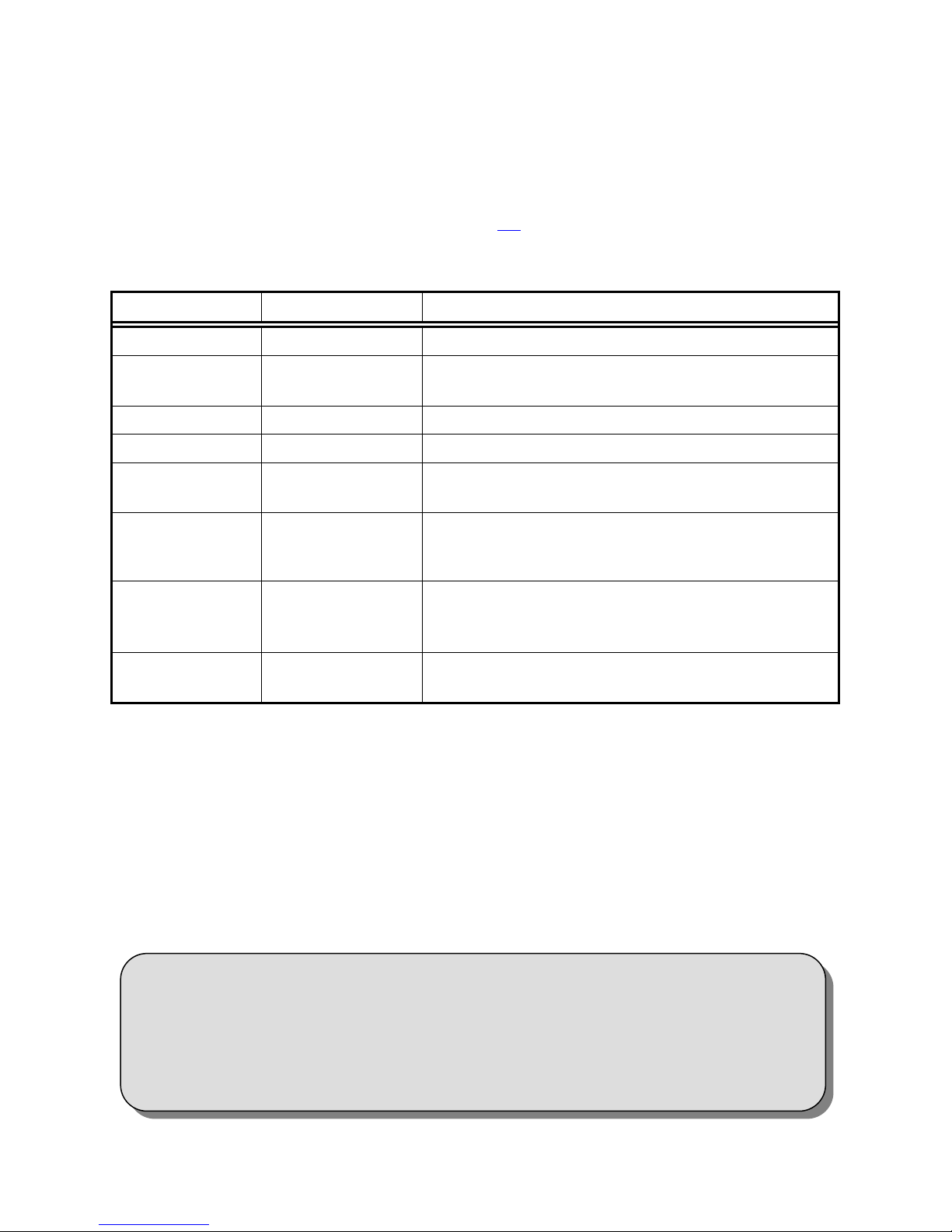
Table 2. DVR395/DVR396 Interconnect Descriptions
Signal Connector Description
RF IN F 950 to 2150 MHz signal accepted
COMPOSITE
VIDEO OUT
S-VIDEO OUT S-video NTSC or PAL
AUDIO OUT Two phono jacks Audio stereo
SERIAL PORT RJ-12 Serial Asynchronous Data. May be used for terminal,
MODE SWITCH 4 Position DIP
ALARM Terminal Strip Receiver alarm contacts,
CLOSURE Terminal Strip Solid state switch closures defined by the network
Connect the receiver to the desired equipment as follows:
CHASSIS GROUND
Phono Jack NTSC or PAL
printer, modem, or local COMPEL control.
Control DIP switches for NTSC/PAL; Modulator
channel 2/3; Normal Video, Color Bars; and LNB
Voltage ON/OFF.
Alarm : NC connects to COM
NORMAL : NO connects to COM
control systems or equipment status.
Using #12 AWG or larger wire, connect the ground to a system or rack ground.
RF IN
Using 75 Ohm coaxial cable with a type F connector, connect your RF source to the RF
IN connector.
When connecting cables to “F” type connectors apply a force of no
more than 12 inch/lb. (Finger tight). Avoid connecting adapters
directly to “F” type connectors. Use at minimum a 1-foot flexible
extension cable between “F” type connectors and adapters.
DVR395/DVR396-002 Page 14 of 30
* * * CAUTION * * *
Page 15
Page 15
VIDEO CONNECTIONS
Composite: connect the composite video output to the desired unit using a standard
phono plug cable. The equipment it is connected to MUST have a 75-ohm termination.
S-video: connect the S-video output to the desired unit using a standard S-video miniDIN connector.
AUDIO CONNECTIONS
Using standard shielded audio cable with phono plugs, connect the stereo audio output to
the desired unit or equipment.
Serial Port
Using a cable terminated in an RJ-12 connector at one end and a DB9/DB25 at the other,
connect the serial port to a terminal, printer, modem, or COMPEL control system.
A Null modem cable or adapter is required for use with a modem. Defaults are
19.2KBps, N, 8, in terminal mode.
DVR395
RJ-12
PIN SIGNAL PIN SIGNAL PIN SIGNAL
2 TX DATA 2 RX DATA 3 RX DATA
3 RX DATA 3 TX DATA 2 TX DATA
5 GROUND 5 GROUND 7 GROUND
6 RI 9 RI 22 RI
MODE SWITCH
Set the control DIP switches for NTSC/PAL, Modulator channel 2/3, Normal Video,
Color Bars, and LNB ON/OFF as required for your system. See Section 2.2
for DIP switch information. FUNCTIONS ARE MODEL SPECIFIC.
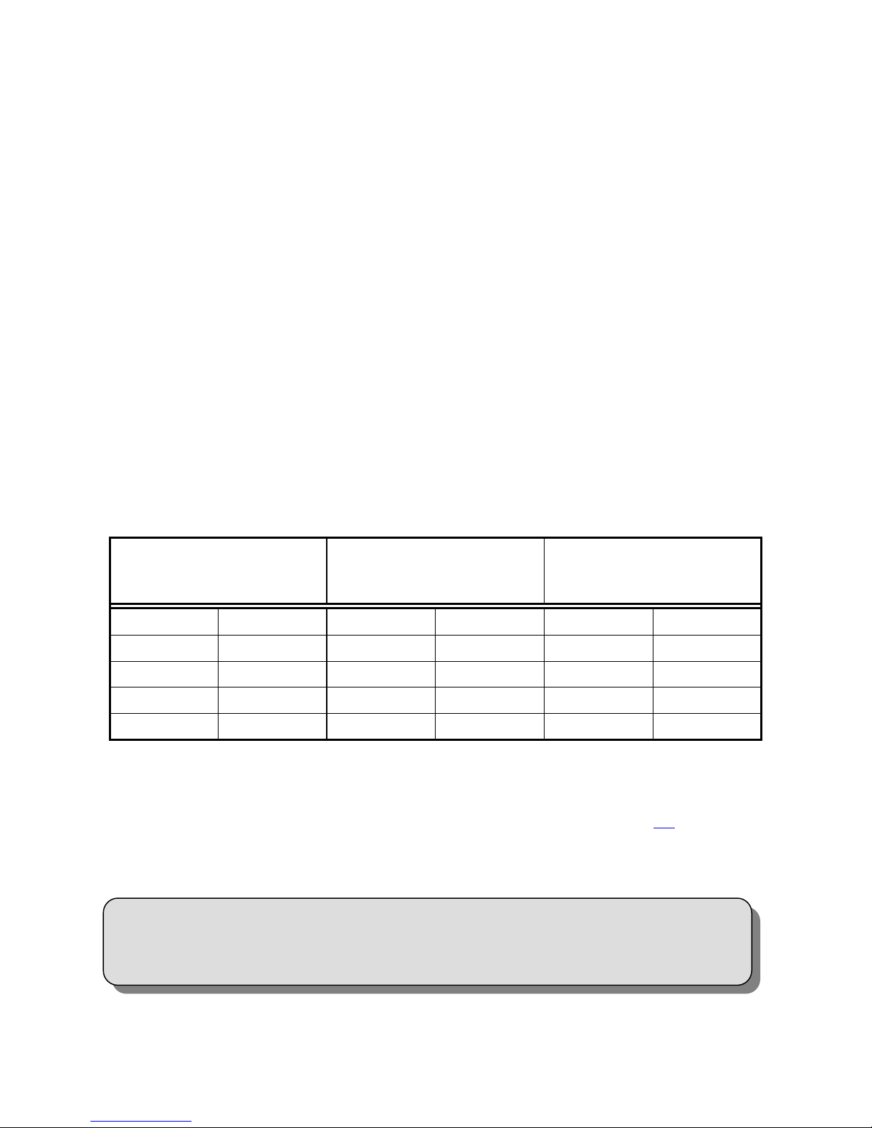
Table 3. DVR395 Serial Cables To Terminal or Printer
COMPUTER
DB-9 (Female)
ASCII TERMINAL OR
SERIAL PRINTER
DB-25 (Male)
(Page 17)
Page 15 of 30 DVR395/DVR396-002
DO NOT CONNECT RJ-12 DIRECTLY TO PHONE LINE.
* * * CAUTION * * *
Page 16

Page 16
1.6 TECHNICAL SUPPORT
In the event the unit fails to perform as described, contact Wegener Communications Customer
Service at (770) 814-4057, FAX (770) 232-0621, or email “[email protected]”.
To return a product for service:
1. Obtain a Return Material Authorization (RMA) number by completing and faxing a copy of
the RMA Form (See Section 1.6,
information instead to:
2. Plainly write the RMA number on the OUTSIDE of the product-shipping container.
NOTE: Writing the RMA number on the outside of the shipping container will
help us to return your equipment to you sooner. Thank you.
3. Return the product, freight prepaid, to the address below:
Page 16) to (770) 232-0621. You may email the same
Service Department RMA# ________
Wegener Communications, Inc.
359 Curie Drive
Alpharetta, GA 30005
NOTE: All returned material must be shipped freight prepaid.
C.O.D. shipments will not be accepted.
Please contact Customer Service at one of the numbers above if you have any questions
regarding service procedures.
1.7 MANUALS
If you have any suggestions concerning this, or any Wegener Manual, you can E-mail them to
[email protected]. If you would rather mail them, please do so to the address shown
below. Our preference is that you copy the page(s) in question, mark it up, and fax or mail us the
copy. We do appreciate constructive criticism. The Fax Number is 770-497-0411.
Attn: Manuals
Wegener Communications, Inc.
11350 Technology Circle
Duluth, GA 30097
DVR395/DVR396-002 Page 16 of 30
Page 17

Page 17
SECTION 2
POWER ON PROCEDURES
2.1 GENERAL
This section provides information and procedures for powering up the unit.
2.2 CONTROL DIP SWITCHES
A four position DIP switch on the rear panel provides manual control and setup selection. Mode
setting is as follows: (In setting the DIP switches, "D" = down and "U" = up, "X" = don't care
for this function).
Table 4. Control DIP Switch Functions
Mode Function
1 2 3 4
Setup Functions
U X X X NTSC Video System*
D X X X PAL Video System*
X U X X Modulator Channel 3 (MODEL SPECIFIC)
X D X X Modulator Channel 2 (MODEL SPECIFIC)
X X U X Normal video
X X D X Color Bars, Tones
X X X U LNB Power OFF
X X X D LNB Power ON
Set the switches to the settings appropriate for your system.
* The receiver must be set to the same format (NTSC or PAL) as the desired channel being
received. The receiver will not operate correctly with incompatible settings.
2.3 FRONT PANEL CONTROLS AND INDICATORS
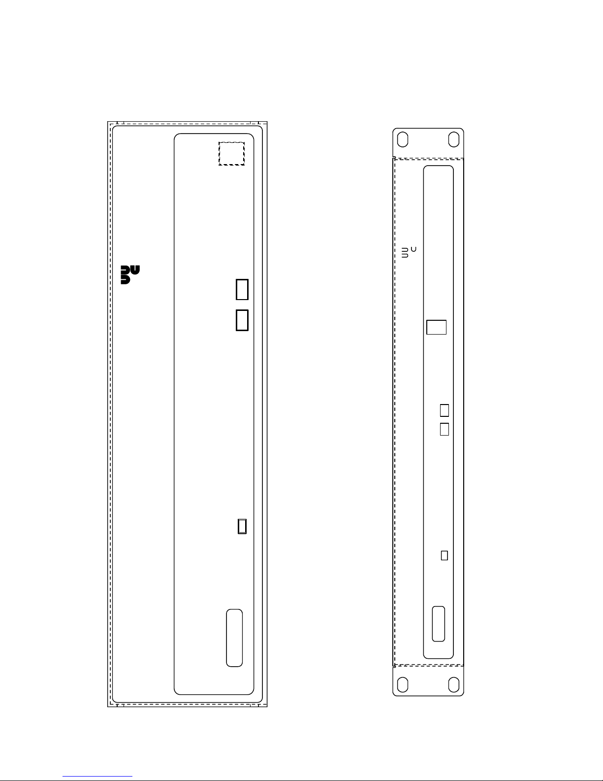
The front panel indicators and controls are shown in Figure 4 (Page 18) and Figure 5 (Page 18),
and described in Table 4
Page 17 of 30 DVR395/DVR396-002
(Page 17).
Page 18
Page 18
Figure 4. DVR395 Front Panel Figure 5. DVR396 Front Panel
WEGENER
WEGENER
COMMUNICATIONS
MPEG-2 IRD COMMUNICATIONS
MODEL DVR395
STATUS SELECT ENTER
S/N
ENTERSELECT
MPEG-2 IRD
STATUS
MODEL DVR396
S/N
DVR395/DVR396-002 Page 18 of 30
Page 19
Page 19
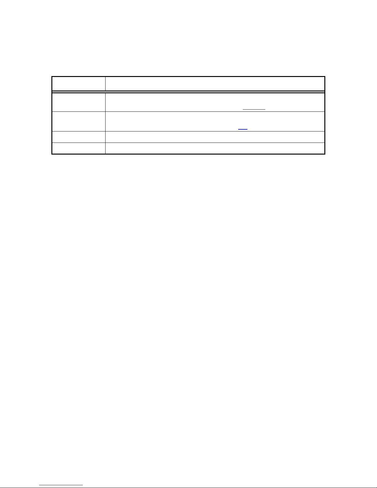
Table 5. Front Panel Controls and Indicator
Item Description
IRD Status
A Red/Green/Amber LED used to show operating status, including
normal operation, warnings, and alarms. See Table 6 (Page 20).
On Screen
Display (OSD)
On Screen Display of IRD may be activated by pressing the <SELECT>
front panel push-button switch. See Section 3.2 (Page 23).
Select Push button activates OSD and selects options displayed.
Enter Push button enters options selected on OSD.
2.4 LED & ALARM/WARNING CONDITIONS
The unit's only LED is RED/GREEN/AMBER, located on the front panel, and labeled Status.
The LED's behavior is described in the following table, which includes a list of warning, alarm,
and boot fail conditions.
Page 19 of 30 DVR395/DVR396-002
Page 20

Page 20
Table 6. LED Indications
Mode Condition Status LED
Power Up IRD is in process of powering up RED/GREEN Blink Pattern
Boot Fail EEPROM Boot Failure RED
Receiver Board Diagnostics Failure RED
Receiver Board Communications Failure RED
Secure micro / Host ID mismatch RED
Alarm Receiver Board Run-Time Failure RED Blink w/ Count = 1
In Fade Mode > 5 seconds (See Warnings Below.) RED Blink w/ Count = 2
Installation Mode > 5 seconds (See Warnings
RED Blink w/ Count = 3
Below.)
Carrier Table Search Mode RED Blink w/ Count = 4
Header Search Mode RED Blink w/ Count = 5
Satellite Search Mode RED Blink w/ Count = 6
Alarming Eb/No (and locked on carrier) (See
RED Blink w/ Count = 7
Warnings Below.)
No MPEG Data > 5 seconds (but locked on carrier)
RED Blink w/ Count = 8
(See Warnings Below.)
No Video Data > 5 seconds (but have MPEG data)
RED Blink w/ Count = 9
(See Warnings Below.)
NTSC - PAL mismatch. RED Blink w/ Count = 10
No Audio Program Table RED Blink w/ Count = 11
Warning Secure Micro Routine Failure AMBER Blink w/ Count = 1
Marginal Eb/No (and locked on carrier) AMBER Blink w/ Count = 2
COMPEL Required and No COMPEL within last 2
AMBER Blink w/ Count = 3
minutes
Audio Free Running AMBER Blink w/ Count = 4
No MPEG data < 5 seconds AMBER
No Video Data < 5 seconds AMBER
Fade or Installation Mode < 5 seconds AMBER
Normal Normal Mode for a COMPEL-not-Required Unit GREEN
COMPEL addressed within last 5 seconds GREEN Flutter
COMPEL addressed within last 2 minutes GREEN
DVR395/DVR396-002 Page 20 of 30
Page 21

Page 21
The following definitions apply to Table 6:
Blink - LED is OFF for 1 second, and then blinks on count times (ON for 250 ms
and OFF for 250 ms). This overall pattern is continued.
Flutter - ON for 50 ms, OFF for 50 ms, repeating….
AMBER - RED and GREEN turned ON at the same time.
Note: ms = 1/1000 second
The conditions are listed in the order of their display priority with highest priority at top. For
example, if the unit is in Satellite Search Mode, and there is an NTSC/PAL mismatch, the LED
should indicate the Satellite Search condition.
Note that the alarm conditions are those conditions preventing the delivery of video.
2.5 POWER ON PROCEDURE
Apply power to the receiver. The unit performs a quick checksum test on the EEPROM
(electrically erasable programmable read only memory). When the test passes, the unit initializes
various devices and configures itself according to the EEPROM settings. It then waits for the
receiver board to complete its power up test, which takes about 10 seconds. When the receiver
board passes its test, the IRD sends a tune request to the receiver board and the Welcome
Banner, shown in Figure 6 (Page 21), to the serial port. If you are in Terminal mode, the banner
displays on the terminal screen. Otherwise, “ALARM: INSTALLATION” displays on the
monitor screen. The IRD then enters alarm mode until all of the alarm conditions are cleared.
X.X is the application code's version number. The text at the bottom of the screen is shown only
if the serial device is set to Terminal mode.
*
Wegener Communications Copyright 1997
MPEG 2 Integrated Receiver Decoder
Firmware Version x.x
*
EEPROM Failure
Receiver Board Diagnostics Failure
Receiver Board Communications Failure
Figure 6. Welcome Banner Figure 7. Failure Banner
* These screens are available in units with firmware versions 2.0 and above.
Page 21 of 30 DVR395/DVR396-002
Page 22

Page 22
This Page Intentionally Left Blank
DVR395/DVR396-002 Page 22 of 30
Page 23
Page 23
SECTION 3
SETUP
3.1 GENERAL
This section provides procedures for initial setup of the unit.
3.2 ON SCREEN DISPLAY (OSD)
The OSD information is contained in the video output from the receiver. It is turned on by
pressing either the <SELECT> or <ENTER> push-button on the front panel. The display is
removed by selecting Exit from the Main Menu. When a menu is first shown, the cursor is
always placed on its first action field (or action with edit field, which ever is first).
The OSD provides the following information and actions:
1. Carrier Status.
2. Signal Strength Monitoring.
3. Selecting the Perm Settings
4. Selecting the Serial Port device.
5. Software Version.
All menus are white text with a solid blue background with highlight as blue text on white
background. There are four field types: Action, Action w/ Edit, Edit, Edit w/ Choices. The
cursor can be moved only to these fields. The function of the <SELECT> and <ENTER> pushbutton for each field type is described below.
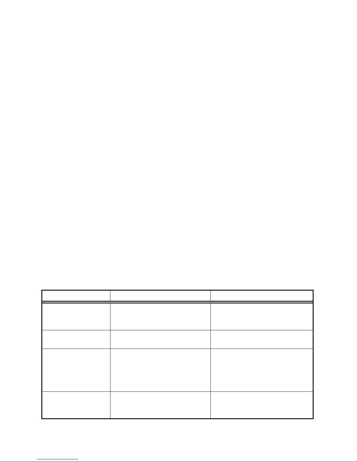
Table 7. SELECT And ENTER Key Functions
FIELD SELECT ENTER
Action Field Moves cursor to next action field
(or action w/ edit field, which
ever is next). Wraps at end.
Action w/ Edit Field Same as for action field. Moves cursor to corresponding
Edit Field If cursor is not on last digit within
edit field, moves cursor to next
digit. Else, moves to next action
field (or action w/ edit field,
which ever is next)
Edit Field w/ Choices Moves cursor to next action field
(or action w/ edit field, which
ever is next).
Page 23 of 30 DVR395/DVR396-002
Takes action on the current field.
edit field.
Increments current digit within
edit field. Wraps back to
beginning at 9.
Scrolls through list of choices.
Wraps back to beginning on last.
Page 24

Page 24
3.3 CUSTOMIZING SETTINGS FOR YOUR SYSTEM
You can customize the settings of the DVR395 to fit your system using the OSD and front panel
push buttons.
To edit settings, perform the following procedures and
see Table 7 (Page 23).
• Power up the unit.
Main Menu
Carrier Status
Signal Strength
• Connect a terminal for the On Screen Display.
See Section 3.2 (Page 23).
• Access the Main Menu by pressing either the
<SELECT> or <ENTER> push button on the
front panel.
Carrier Select
Serial Port Select
Software Version
Exit
• Using the front Panel <SELECT> button,
select/highlight the item you wish to edit.
• Press the <ENTER> push button to display that screen.
NOTE: The values shown on the following screens are examples only, and will likely be
different in normal operation.
For Carrier Select:
• From the Main Menu, select “Carrier Select.”
• Press <ENTER> to display the “Carrier Select”
screen.
• Press <ENTER> to enter the edit field.
• Use <SELECT> to place the cursor on the digit to
be edited.
• Use the <ENTER> button to cycle the digit.
• Use <SELECT> to move to the next item in the
scroll menu.
From Table: 3
Carrier (MHz): 12000.00
Data Rate (Mbps) 4.992
FEC Rate: ½
Tag Site: 0
MPEG Mode: TRANSPORT
LNB LO (MHz) 10750.00
CARRIER SELECT
Activate Selection
Return To Main Menu
• Make further edits, if desired.
• Use <SELECT> to highlight “Activate Selection.”
• Press <ENTER> to save the new settings and exit this screen.
• To exit without saving the changes, Select “Return To Main Menu” and press <ENTER>.
DVR395/DVR396-002 Page 24 of 30
Page 25
Page 25
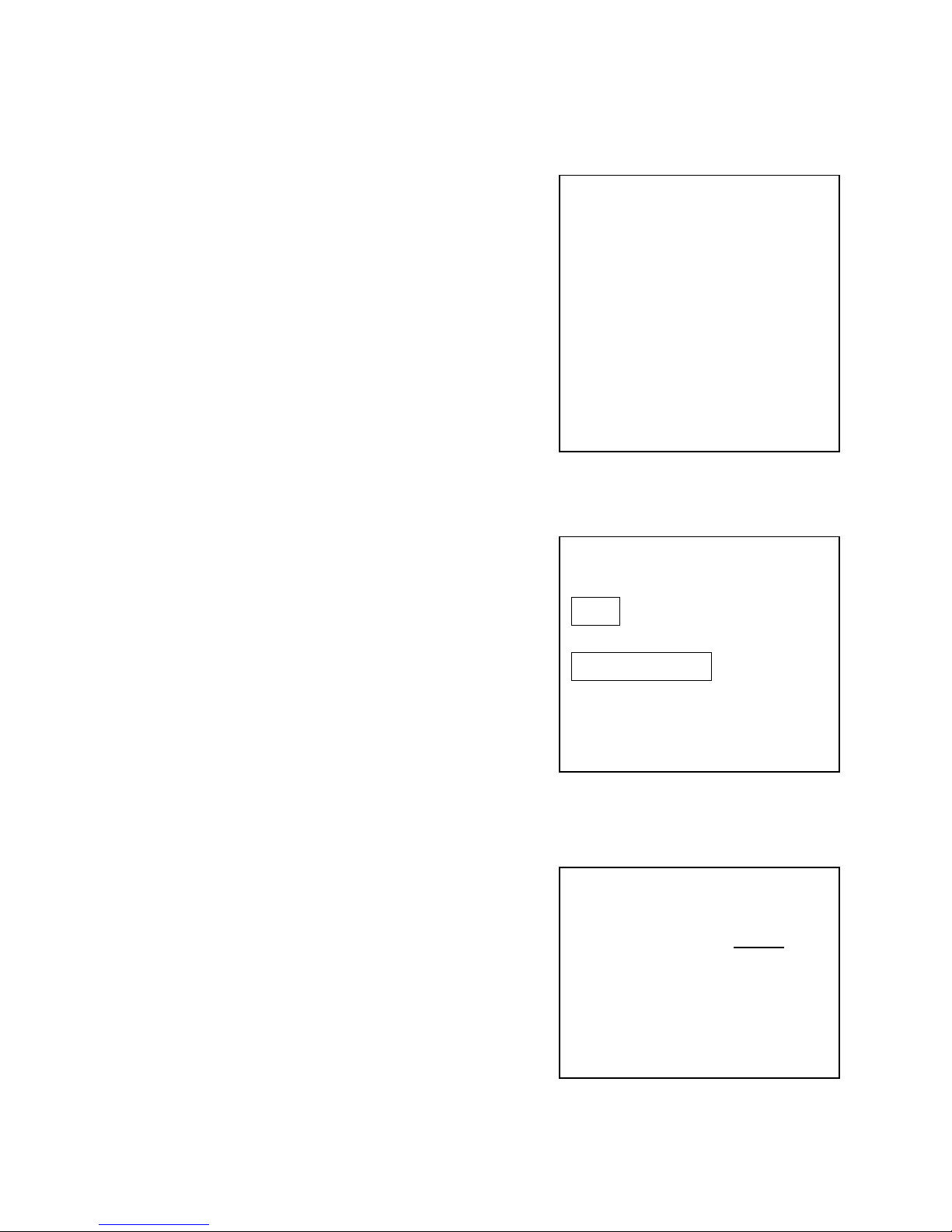
For Carrier Status:
• From the Main Menu, select “Carrier Status.”
• Press <ENTER> to display the “Carrier Status”
screen.
• This is a read-only screen.
• Press <ENTER> to Return to the Main Menu.
For Signal Strength:
• From the Main Menu, select “Signal Strength”
and Press <ENTER> to display this screen
• Displays signal level. The upper bar is the signal
strength. The lower bar gives a higher resolution
of and deviation from the selected value.
• To use the lower bar, select “Calibrate” and Press
<ENTER>.
• To exit this screen, select “Return To Main
Menu” and press <ENTER>.
CARRIER STATUS
Acquisition Mode: INSTALL
Carrier (MHz): 12000.00
Data Rate (Mbps): 5.000
FEC Rate: 1/2
Tag Site: 0
MP56 Mode: 0
AVG. Eb/No (dB): 8.0 dB
Current Eb/No dB: 8.5 dB
Return To Main Menu
SIGNAL STRENGTH
l l l l l l l l l l l l l l l l l
l ^ l
Calibrate
Return To Main Menu
For Serial Port Select:
• From the Main Menu, select “Serial Port Select”
and Press <ENTER> .
• Use <ENTER> to scroll the possible devices.
• When the desired device is displayed, press
<SELECT> to highlight “Activate Selection.”
• Press <ENTER> to save the change and exit this
menu.
• To exit without saving the changes, select “Return To Main Menu” and Press <ENTER>.
Page 25 of 30 DVR395/DVR396-002
SERIAL PORT SELECT
Device: Printer
Activate Selection
Return To Main Menu
Page 26

Page 26
For Software Version:
This is a read-only screen showing the versions of the
various software packages.
• Select “Software Version” from the Main Menu
and press <ENTER> to display the screen.
• Press <ENTER> to return to the Main Menu.
SOFTWARE SELECT
Application: V1.3
Receiver: 17 (Type 48)
Video Decoder: 01.70
Audio Decoder: BEPD0306
Descrambler: r40_721b.hex
Boot: 1.2
DSP Demux: V1.1
Return To Main Menu
DVR395/DVR396-002 Page 26 of 30
Page 27

Page 27
APPENDIX A
RMA REQUEST FORM
Not every system or location will use the RMA Request Form shown on the following page. It is
provided as a convenience for those customers who send units directly to Wegener
Communications, Inc. for repair.
If there is any doubt regarding use of this form, contact Network Control or other higher
authority for guidance.
Page 27 of 30 DVR395/DVR396-002
Page 28
Page 28
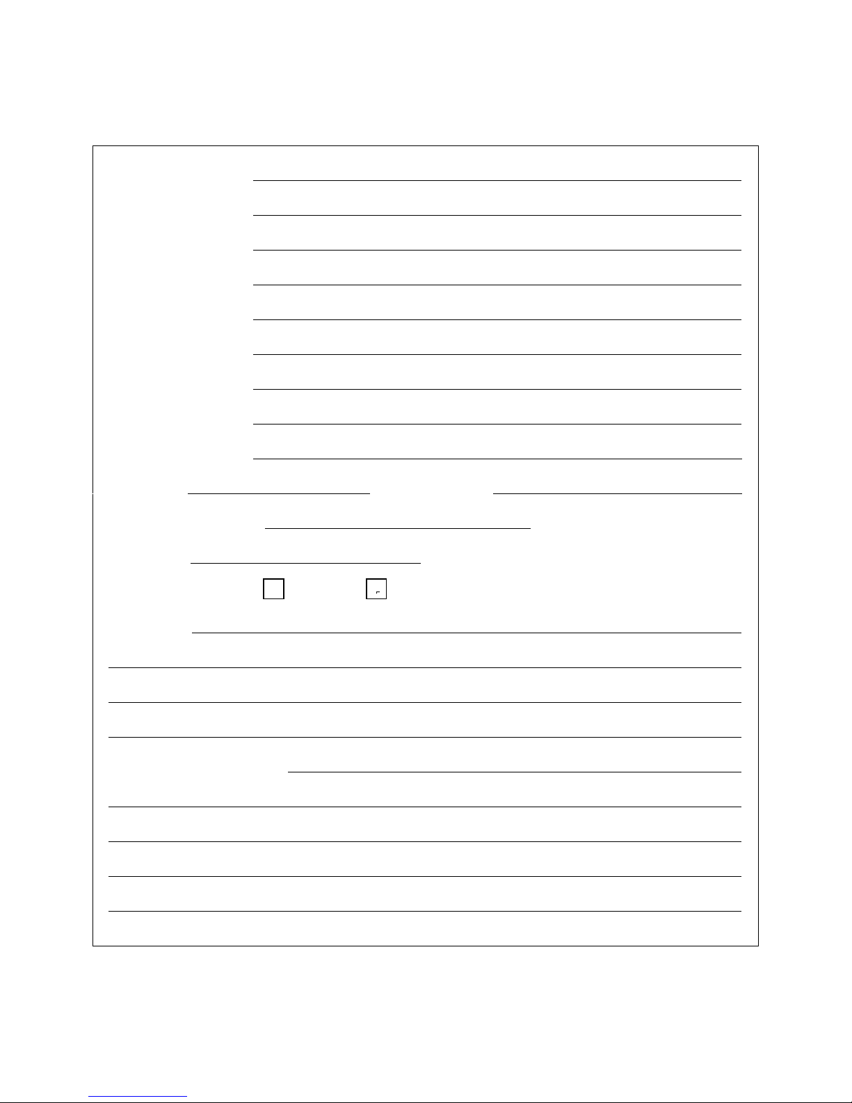
RMA REQUEST FORM
Fax (770) 232-0621
Company Name:
Bill-To Address:
Ship-To Address:
Contact Name:
Phone # ( ) - Fax #: ( ) -
Complete Model #:
Serial #:
In Warranty: Yes No
Problem:
Additional Comments:
DVR395/DVR396-002 Page 28 of 30
Page 29
Page 29
RECORD OF REVISIONS
Date of
Change
Rev.
Level
Page
No.
Description of Change
7/19/97 A Initial Release
8/27/99 B 10
11
4/7/00 C 10
10
11
11/14/00 D 5
12
19
20
24-26
27
Changed “RJ-11” to “RJ-12.”
Table 3, Reversed Ch. 2 & 3 in “Function” Column.
Added Sections 1.3.3 – 1.3.7
Added Metric equivalent measurements
Added Ferrite Installation Instructions.
Added instructions for accessing manuals on the web.
Corrected connector numbers for larger ferrites.
Revised Description of Status LED.
Added/Corrected Warning LED Descriptions.
Clarified minor points in Menu screen instructions. Added
statement that sample screens were only examples.
Added Note that RMA Form may not be for every user.
12/15/00 E Added connector pinouts.
Page 29 of 30 DVR395/DVR396-002
Page 30

Page 30
SERVICE RETURN ADDRESS
Service Department RMA# ________
Wegener Communications, Inc.
359 Curie Drive
Alpharetta, GA 30005
CONTACT NUMBERS AND ADDRESSES
Voice: (770) 814-4057
FAX: (770) 232-0621
email: [email protected]
DVR395/DVR396-002 Page 30 of 30
 Loading...