

Page 1
DTV742 Installation Quick Start Guide
The Wegener Model DTV742 8VSB 4-Channel Multiplexor receives VHF/UHF broadcast HDTV signals and provides output ASI
streams for connection to cable system QAM modulators. This guide provides information for setting up and operating the DTV742.
Additional information may be found on the Wegener web site at www.wegener.com/
In addition to this guide, your box should include:
1. DTV742 8VSB 4-Channel Multiplexor
2. Power cord 3. UL safety sheet
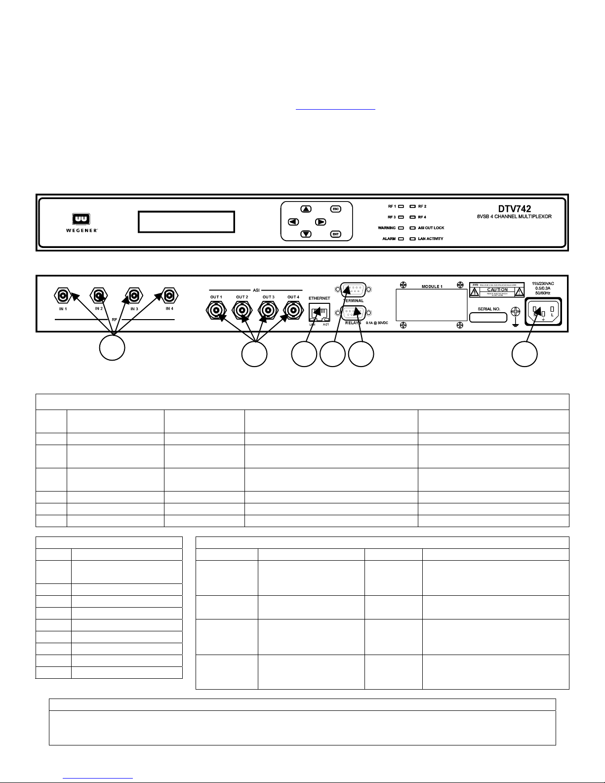
Front and Rear Panel View
1
2
3
4 6
5
Connector/Pin-out Information
Rear-Panel Connector Descriptions
Connector
Ref
Designation Type Signal Name Description
1 RF In 1, 2, 3, & 4 Type F RF IN 1, RF IN 2, RF IN 3, & RF IN 4 From VHF/UHF Antenna
2 ASI Out 1, 2, 3, & 4 BNC
3 Ethernet RJ-45 jack Ethernet_In & Out
4 Terminal DB-9 female RxD (output) & TxD (input) To Local Terminal
5 Relays DB-9 female Alarm, Warning, & Contact Closures To Alarm Monitoring
6 115/230 VAC IEC receptacle AC Line In To AC Power Outlet
Status Relays Signals(Ref 4) LED Indicator Descriptions
Pin # Function LED Description LED Description
Close on Alarm or
9
power failure
4Alarm COM
8 Close on Warning
3 Warning COM
6 Open on Warning
1 Not used
7 Open on Alarm
2 Not used
5Ground
RF 1
RF 3
WARNING
ALARM
ASI OUT 1, ASI OUT 2, ASI OUT 3,
& ASI Out 2
ON – Tracking carrier
OFF – No carrier
ON - Tracking carrier
OFF – No carrier
ON – See LCD / web
browser for details
OFF – No Warnings
ON – See LCD / web
browser for details
OFF – No alarms
RF 2
RF 4
ASI OUT
LOCK
LAN
ACTIVITY
To Advanced Cable Channel
Groomer, DTV700, or ASI Mux
To LAN – for Web Interface
Control
ON – Tracking carrier
OFF – No carrier
ON – Tracking carrier
OFF – No carrier
ON – ASI output active
OFF – No ASI output
BLINKS – parameter is being
changed via browser or SNMP
The unit tunes and demodulates 8VSB ATSC broadcast signals which are converted to ASI output transport
streams. Selected programs and PSIP data received are passed through to the output ASI ports. PSIP
processing may be enabled or disabled.
800057-02 Rev. A Page 1 of 11 May 24, 2003
Program and PSIP Processing
Page 2
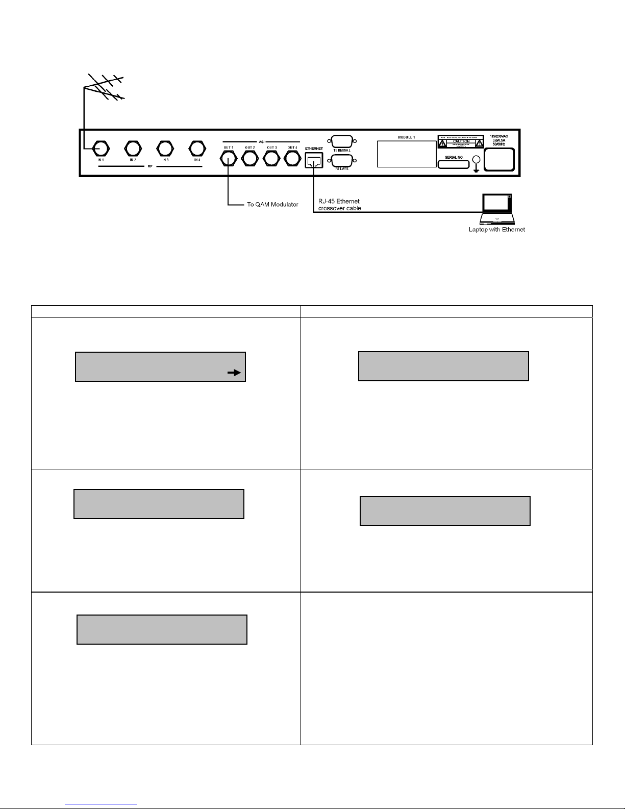
Basic System Setup Diagram
V
V
N
Front-panel User Interface
Note that from any screen, pressing the ESC key twice will return you to the Home Screen.
Main-level Screens Second-level Screens
Home Screen (rotates through data from each of the four RF
inputs)
RF3 CHAN:20 8VSB
SNR21.5 ErrSec:0002
The channel number, modulation type (8VSB, 64QAM, or
256QAM), signal-to-noise ratio, and errored seconds are
displayed for each input.
Press the 4 key (if displayed) to go to Alarms/Warnings.
Press the ENT key to view the second-level Serial Number
and Application Software Version Number screen.
Alarms/Warnings
iew Alarms/Warnings
Press the ENT key to view any active alarms or warnings on
the second-level Alarms/Warnings Message screen.
Press the 4 key to go to Clear Errored Seconds (if counter is
non-zero) or Program Setup.
Press the ESC key to go to the Home Screen.
Clear Errored Seconds
Clear Errored Secs
Press<ENT>
This screen only appears if the errored seconds counter is
non-zero. Otherwise the next screen, Program Setup is
displayed.
Press the ENT to clear the errored seconds counter.
Press the 4 key to go to the Input Setup screen.
Press the 3 key to go to Alarms/Warnings.
Press the ESC key to go to the Home Screen.
Serial Number and Application Software Version Number
Screen
S/N:XXXXXX
ER:YYY
Where XXXXXX is the unit's six-digit serial number and YYY is
the version number of the unit's currently installed application
software.
Press the ESC key to go to the Home Screen.
nd
2
-level Alarms/Warnings Message Screen
o Alarms or Warnings
Any active alarms or warnings are described here.
Press the 4 key to view the next alarm or warning (if more than
one).
Press the ESC key to return to the Alarms/Warnings screen.
800057-02 Rev. A Page 2 of 11 May 24, 2003
Page 3
Main-level Screens Second-level Screens
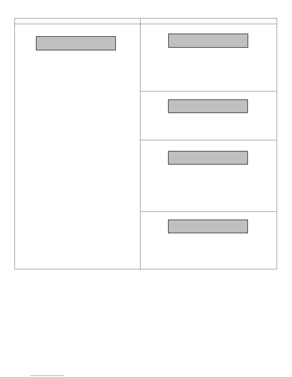
Input Setup
Input Setup...
Press the ENT key to bring up the second-level Program
Input screen.
Press the 4 key to go to Program Status.
Press the 3 key to go to Clear Errored Seconds (if counter is
non-zero) or Alarms/Warnings.
Press the ESC key to go to the Home Screen.
2nd-level RF Input
RF Input X
Where X is the RF port number.
Press ENT to go to the third-level Input Setup Screens below and
use the 5 or 6keys to select <ON> or <OFF>, adding or
removing this program to/from the output stream. Press ENT
again to confirm.
Press the 4 key to go to the next RF Input screen (1 through 4).
Press the ESC key to return to the Input Setup screen.
3rd-level Tuner Enable
Tuner Enable:
Press the ENT key to toggle between ON and OFF, enabling or
disabling the tuner.
Press the 4 key to go to the Channel Number Selection screen.
Press the ESC key to return to the second-level RF Input screen.
3rd-level Channel Number Selection
Channel Number: XX
Where XX is the current channel number.
Press ENT to enter the edit mode and use the 5 or 6keys to
change the channel number. Press ENT again to confirm your
selection or ESC to cancel changes.
Press the 4 key to go to the RF Standard screen.
Press the 3 key to go to the Tuner Enable screen.
Press the ESC key to return to the second-level RF Input screen.
rd
-level RF Standard
3
RF Standard:
800057-02 Rev. A Page 3 of 11 May 24, 2003
Press ENT and use the 5 or 6keys to toggle the RF Standard
between Broadcast and Cable. Press ENT again to confirm your
selection or ESC to cancel changes.
Press the 3 key to go to the Channel Selection screen.
Press the ESC key to return to the second-level RF Input screen.
Page 4
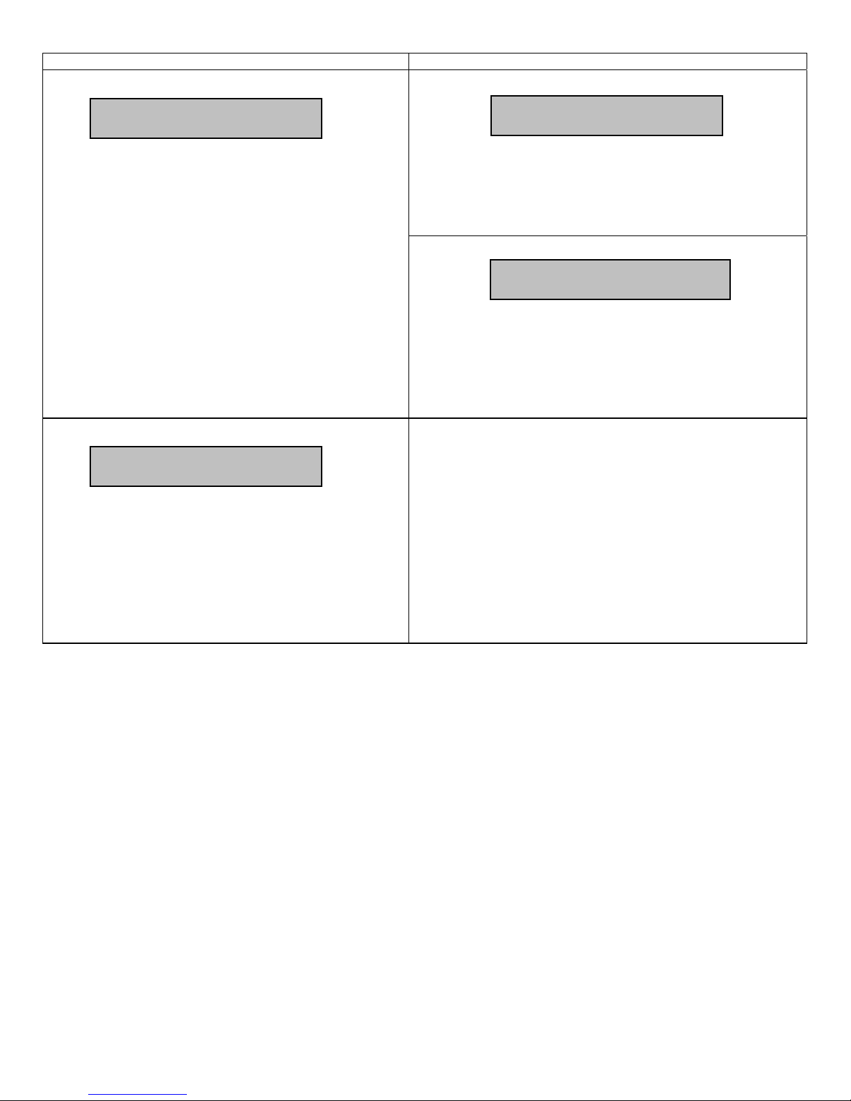
Program Status
Program Status...
Main-level Screens Second-level Screens
2nd -level Program Status
Input Number:X
Press the ENT key to view the second-level program status
screens.
Press the 4 key to go to Panel Help Timeout.
Press the 3 key to go to Input Setup.
Press the ESC key to go to the Home Screen.
Front-panel Help Timeout
Panel Help Timeout
10
Press ENT and then the 5 or 6keys to select the frontpanel help message timeout. Values of 3, 5, 10, 30, or 60
seconds, or No Timeout may be selected.
Press the ENT key to confirm the selection or ESC to cancel
changes.
Press the 4 key to go to IP Setup.
Press the 3 key to go to Program Status.
Press the ESC key to go to the Home Screen.
where X is the input port number.
Press the ENT key to go to the third-level program status screen.
Press the 4 key to go to the next input (1 through 4).
Press the ESC key to return to the main-level Program Status
screen.
rd
3
-level Program Status
ProgIn XXXXX AAAAAAA
Out:Y BBBBBBB
where XXXXX is the program number at input, AAAAAAA is the
service descriptor for the program, Y is the ASI output port, and
BBBBBBB is the available audio on the input for the program (AC3, MPEG, or MPG/AC3).
Press the ESC key to return to the 2
nd
-level Program Status screen.
800057-02 Rev. A Page 4 of 11 May 24, 2003
Page 5
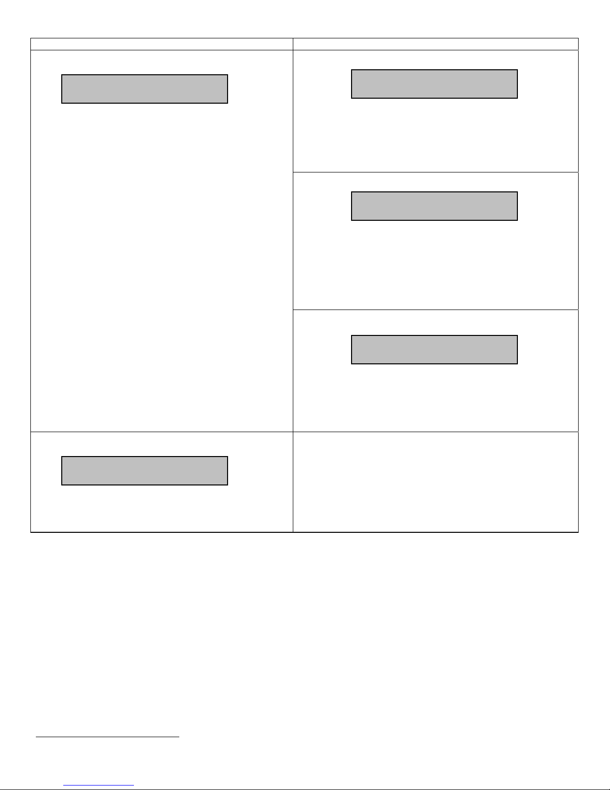
Main-level Screens Second-level Screens
N
IP Setup
IP Setup...
Press the ENT key to go to IP Address Selection.
Press the 4 key to go to Reset Unit.
Press the 3 key to go to Panel Help Timeout.
Press the ESC key to go to the Home Screen.
IP Address Selection
IP Address:
0.0.0.0
Press the ENT key and then press the arrow keys to change the IP
address. Press the ENT key to confirm the selection or ESC to
cancel changes.
Press the 4 key to go to the Netmask Selection.
Press the ESC key to go to IP Setup.
Netmask Selection
etmask:
255.255.0.0
Press the ENT key and then press the arrow keys to change the
Netmask. Press the ENT key to confirm the selection or ESC to
cancel changes.
Press the 4 key to go to Gateway Selection.
Press the 3 key to go to IP Address Selection.
Press the ESC key to go to IP Setup.
Gateway Selection
Gateway:
0.0.0.0
Press the ENT key and then press the arrow keys to change the
Gateway. Press the ENT key to confirm the selection or ESC to
cancel changes.
Press the 3 key to go to Netmask Selection.
Press the ESC key to go to IP Setup.
Unit Reset
Reset Unit...
Press the ENT key to reset the unit and start the bootloader.
Press the 3 key to go to IP Setup.
Press the ESC key or 4 to go to the Home Screen.
Web Browser User Interface
In addition to the front panel, the user may control and monitor the unit using the rear-panel Ethernet connection. Before using the
Ethernet connection, the appropriate IP address, netmask, and gateway must be selected via the front-panel interface. There are two
basic methods of using the Ethernet connection – with a directly connected PC or with a LAN connection.
Locally connected PC –
Connect the DTV744 Ethernet connection to the Ethernet network connector on the PC using a crossover RJ-45 cable (8 pins).
Set the DTV744 IP Setup as follows: IP Address: 172.016.100.020 Netmask: 255.255.000.000
Gateway: 000.000.000.000
Set the PC IP address as follows:
Connect to the DTV742 using the web browser instructions below.
LAN Connection –
Connect the DTV742 Ethernet connection to the LAN using a normal RJ-45 cable (8 pins). Set the DTV744 IP Address, Netmask,
and Gateway as directed by your network administrator. Use any PC on the LAN to connect to the DTV744 using the web browser
instructions below.
1
IP Address: 172.016.100.001 Subnet Mask: 255.255.000.000
1
To change the PC IP address, go to the Settings, Control Panel and double click on the Network icon. Select Configuration, TCP/IP protocol, and click on the
Properties box. Click on Specify IP Address and set the IP Address and Subnet Mask as indicated. Click OK to restart the PC with the new values.
800057-02 Rev. A Page 5 of 11 May 24, 2003
Page 6
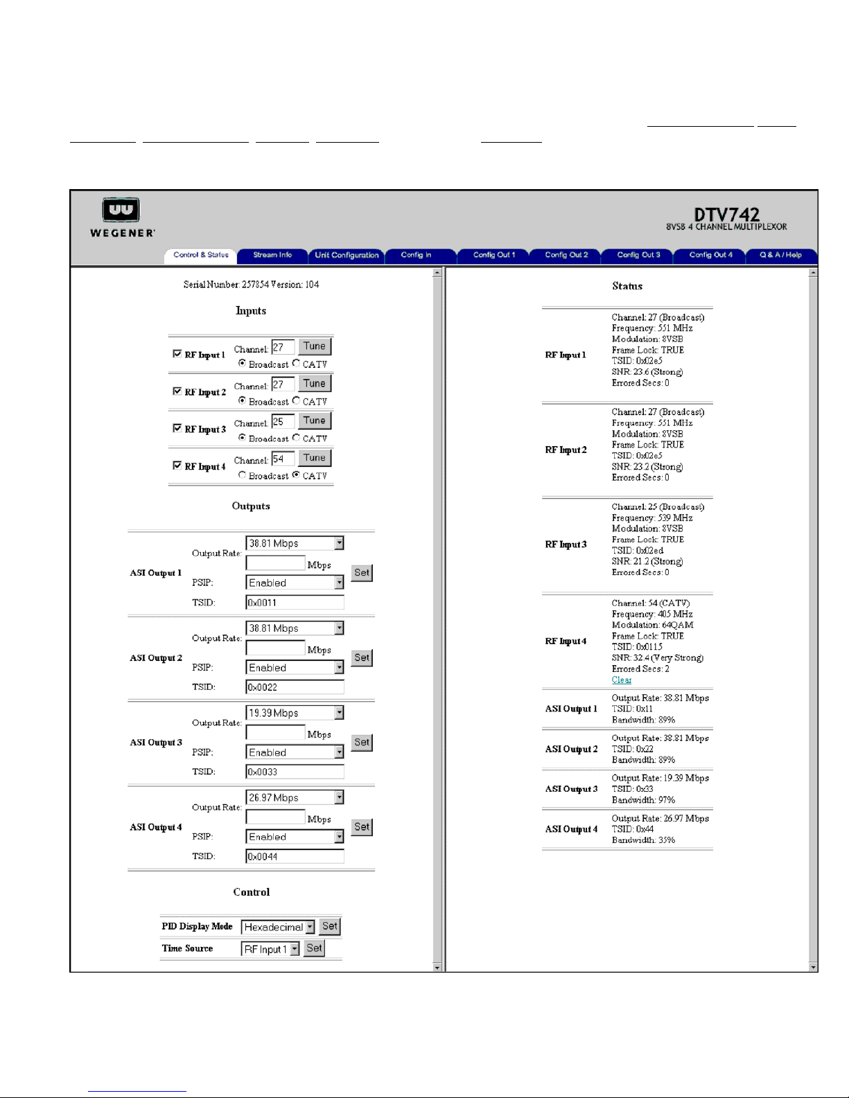
Using the Web Browser –
Using the web browser of your choice, set the Address to http://nnn.nnn.nnn.nnn where nnn.nnn.nnn.nnn is the IP address of
the unit to be controlled. Each unit on the network must have a unique address. You should see the pages below when connected
to the unit. (Be sure that your screen resolution is set to at least 1024x768 so that all items are visible. Lower resolutions will
prevent you from viewing all the available tabs.) You may select which page to view by clicking on the Control and Status, Stream
Information, Unit Configuration, Config In, Config Out (1, 2, 3, or 4), or Q&A/Help tabs.
The Control and Status tab (shown below) allows you to select the channel number for the RF input. The status section provides
signal status.
800057-02 Rev. A Page 6 of 11 May 24, 2003
Page 7
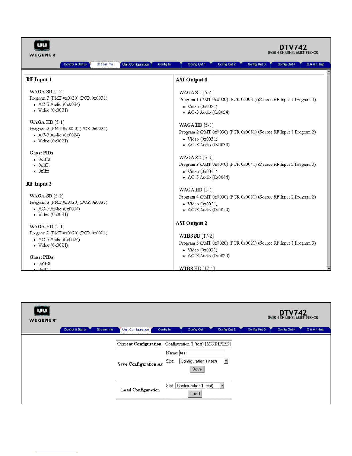
The Stream Information tab below shows input and output status. No user inputs are located on this screen.
The Unit Configuration tab below shows the current configuration in use and allows storage and loading of 10 separate
configurations. A configuration is the set of all user settable items (inputs and outputs) in the unit.
800057-02 Rev. A Page 7 of 11 May 24, 2003
Page 8
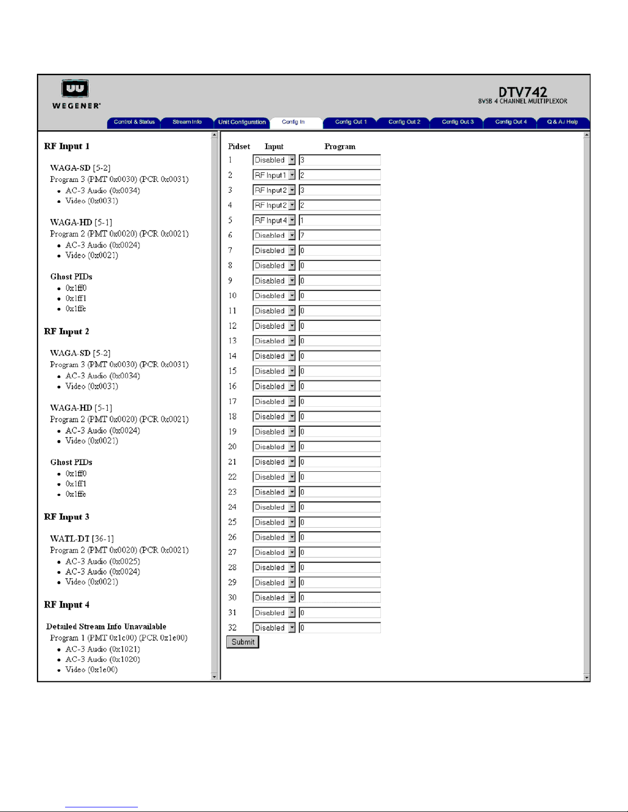
The Config In tab below provides the interface for selecting the RF Input and Program numbers that will be used in all four of the
DTV742’s multiplexors.
800057-02 Rev. A Page 8 of 11 May 24, 2003
Page 9
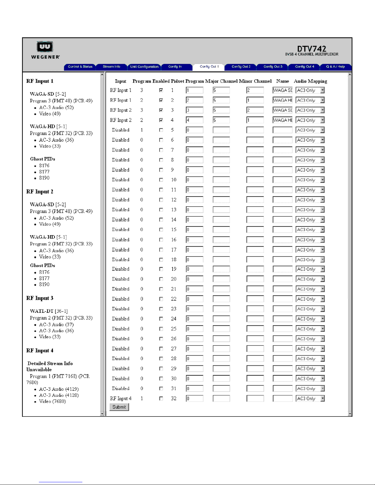
The Config Out tabs (Config Out 1 illustrated below) provide the interface for selecting programs for each of the ASI outputs. A
separate tab is used for each output (1, 2, 3, and 4).
800057-02 Rev. A Page 9 of 11 May 24, 2003
Page 10
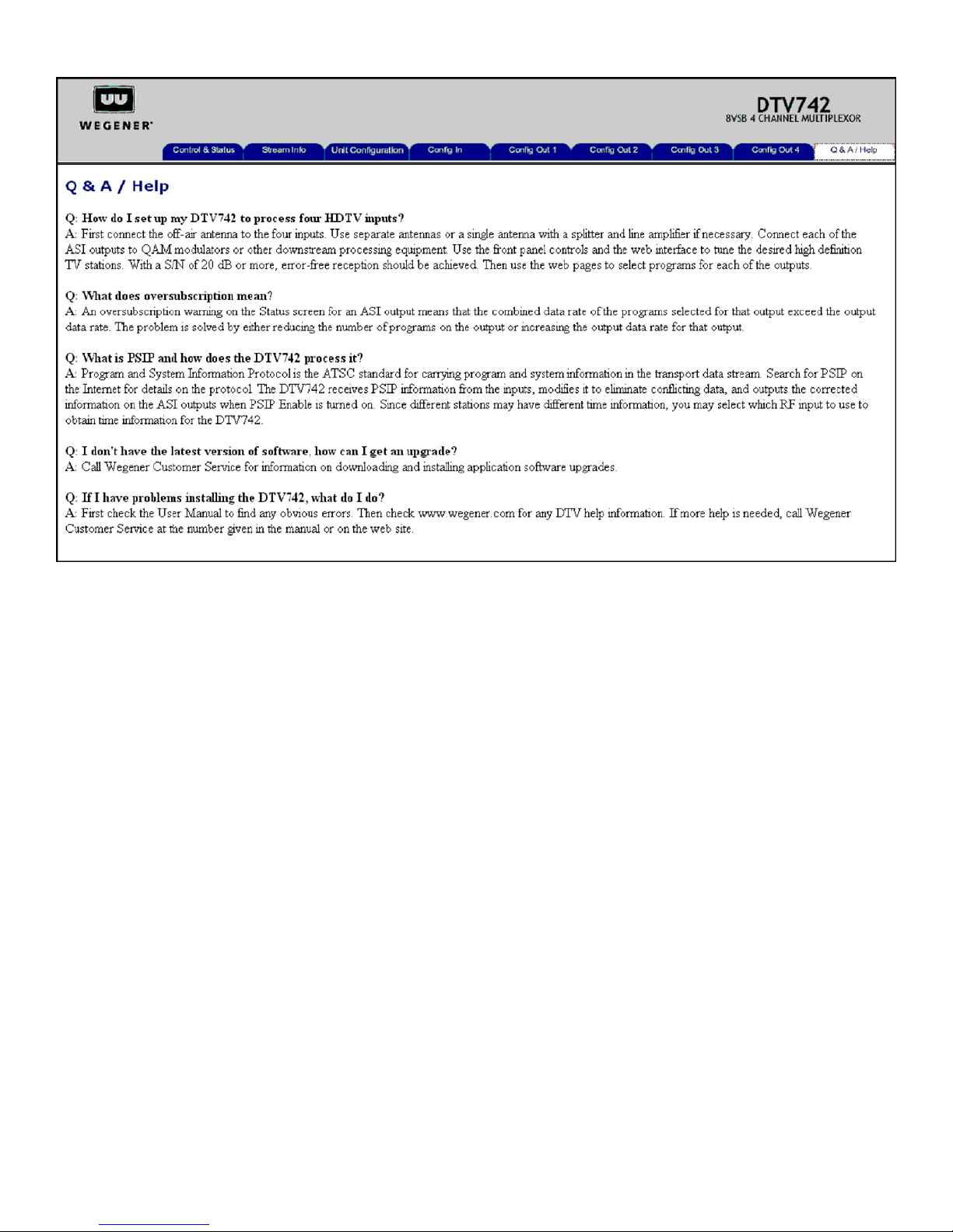
The Q&A/Help tab (shown below) provides answers to commonly asked questions about the DTV744.
800057-02 Rev. A Page 10 of 11 May 24, 2003
Page 11
Notices
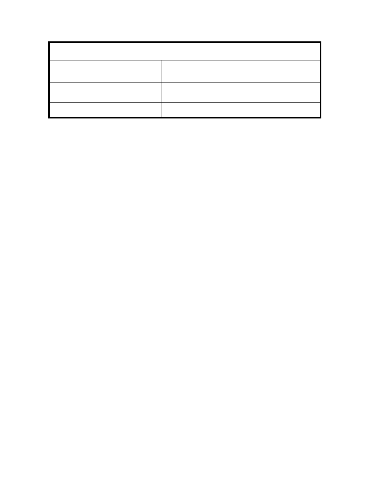
Environmental Operating Conditions & Physical Specifications
Use
Altitude
Temperature Range
Relative Humidity (max.)
Weight
Dimensions (H x W x D)
Input Power Rating 90-132Vac & 175-264Vac, 43 Watt, 50/60 Hz
Elevated Operating Ambient
If equipment is installed in a closed or multi-unit rack assembly, the operating ambient of the rack may be greater than the room ambient. Therefore, considerations
should be given to the TMRA, or Temperature inside the Mounting Rack, and not just inside the room.
Reduced Air Flow
Installation of the equipment in a rack should be such that the amount of airflow required for safe operation of the equipment is not compromised.
Mechanical Loading
Mounting of equipment in a rack should be such that a hazardous condition is not achieved due to uneven loading. This unit is not very heavy, but total rack loading
should be considered.
Indoor
Up to 2000 meters
o
C to 40 o C
10
80% for temperatures up to 31
humidity as 40
10.6 pounds or 4.81 kilograms
3.5”x 19”x 10.5” or 88.9 mm x 482.6 mm x 266.7 mm
o
C.
o
C decreasing linearly to 50% relative
Circuit Overloading
Consideration should be given to the connection of the equipment to the supply circuit and the effect that overloading of circuits could have on over-current protection
and supply wiring. Appropriate consideration of equipment nameplate ratings should be used when addressing this concern.
Reliable Earthing
Reliable earthing of rack-mounted equipment should be maintained. Particular attention should be given to supply connections other than direct connection to the
Branch (use of power strips).
Desktop Installation
To set up the DTV735 in a desktop environment, place it on a flat surface where it will not be subject to being hit or pushed, and will not have anything spilled or
dropped on it. Also, the cables connected to the unit should be routed so they are not hit or pulled, which might cause damage to the connectors or to the unit itself.
Additionally, there should be sufficient flow of cool air so the unit stays within its operating parameters.
Rack Installation
When installed in an equipment rack, it is best that the DTV735 be supported by angle brackets or cross supports. These should be screwed or bolted securely to the
equipment rack, and be capable of supporting the unit and its connecting cables. Do NOT install the unit if you have doubts about the unit being safely supported. There
are also 4 holes in the front brackets, which are designed to accept screws for further anchoring. It is also essential that these brackets be used so the unit cannot be
moved forward and fall from the rack. It is always best to install the angle brackets or cross-members before setting the unit in place. Then, prior to installing cables,
put anchored screws or bolts-and-nuts into place on the front brackets. Failure to do this can lead to pushing the unit out the front of the rack in later steps.
Warranty
The following warranty applies to all Wegener Communications products. All Wegener Communications products are warranted against defective materials and
workmanship for a period of one year after shipment to customer. Wegener Communications' obligation under this warranty is limited to repairing or, at Wegener
Communications' option, replacing parts, subassemblies, or entire assemblies. Wegener Communications shall not be liable for any special, indirect, or consequential
damages. This warranty does not cover parts or equipment, which have been subject to misuse, negligence, or accident by the customer during use. All shipping costs
for warranty repairs shall be prepaid by the customer. There are no other warranties, express or implied, except as stated herein.
Technical Support
In the event the unit fails to perform as described, contact Wegener Communications Customer Service at (770) 814-4057, FAX (678) 624-0294, or E-mail
“[email protected]”.
Corporate Office Service Department
Wegener Wegener
11350 Technology Circle 359 Curie Drive
Duluth, GA 30097 Alpharetta, GA 30005
800057-02 Rev. A Page 11 of 11 May 24, 2003
 Loading...