

Page 1
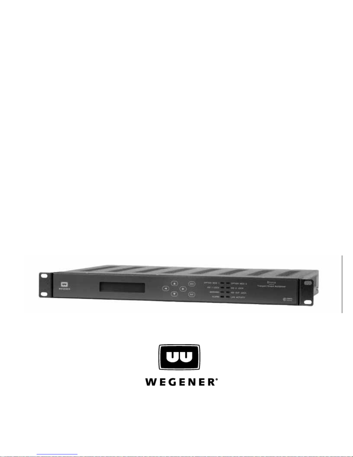
DTV 720
TRANSPORT STREAM MULTIPLEXER
USER’S MANUAL
800043-01 Rev. C
Page 2

DTV 720 USER’S MANUAL
A proven world leader in digital video, audio & broadcast data systems, WEGENER’s management system is certified to ISO 9001:2000.
Data, drawings, and other material contained herein are proprietary to Wegener Communi-
cations, Inc., and may not be reproduced or duplicated in any form without the prior written
permission of Wegener Communications, Inc.
The information contained herein is subject to change without notice. Revisions may be
issued to advise of such changes and/or additions.
2005 Wegener Communications, Inc. All rights reserved.
WEGENER
, and DTV 720 are trademarks of WEGENER Communications, Inc. All other
trademarks are the property of their respective owners.
Correspondence regarding this publication,
800043-01 Revision C
Third Edition: May 2005
should be forwarded to:
Wegener Communications, Inc.
Technology Park/Johns Creek
11350 Technology Circle
Duluth, GA 30097-1502
Phone: 770-814-4000
Fax: 770-623-0698
The Wegener DTV720 is approved under FCC Part 15B Class A, UL1950, and CSA.
800043-01 Rev. C ii www.wegener.com
Page 3

DTV 720 USER’S MANUAL
TABLE OF CONTENTS
CHAPTER 1 GENERAL INFORMATION
1.1 Manual Overview . . . . . . . . . . . . . . . . . . . . . . . . . . . . . . . . . . . . . . . . . . . . . . . . . . . . 1
1.2 DTV720 Overview . . . . . . . . . . . . . . . . . . . . . . . . . . . . . . . . . . . . . . . . . . . . . . . . . . . 2
Physical Description . . . . . . . . . . . . . . . . . . . . . . . . . . . . . . . . . . . . . . . . . . . . . . . . . 2
Features . . . . . . . . . . . . . . . . . . . . . . . . . . . . . . . . . . . . . . . . . . . . . . . . . . . . . . . . . . 2
1.3 DTV720 Specifications. . . . . . . . . . . . . . . . . . . . . . . . . . . . . . . . . . . . . . . . . . . . . . . . 3
1.4 Safety Summary. . . . . . . . . . . . . . . . . . . . . . . . . . . . . . . . . . . . . . . . . . . . . . . . . . . . . 4
1.5 Glossary of Terms and Abbreviations . . . . . . . . . . . . . . . . . . . . . . . . . . . . . . . . . . . . 5
CHAPTER 2 INSTALLATION
2.1 Unpacking and Inspection . . . . . . . . . . . . . . . . . . . . . . . . . . . . . . . . . . . . . . . . . . . . . 7
2.2 Location and Mounting. . . . . . . . . . . . . . . . . . . . . . . . . . . . . . . . . . . . . . . . . . . . . . . . 7
Rack Mounting . . . . . . . . . . . . . . . . . . . . . . . . . . . . . . . . . . . . . . . . . . . . . . . . . . . . . 9
2.3 DTV720 Connections . . . . . . . . . . . . . . . . . . . . . . . . . . . . . . . . . . . . . . . . . . . . . . . . 10
Ethernet. . . . . . . . . . . . . . . . . . . . . . . . . . . . . . . . . . . . . . . . . . . . . . . . . . . . . . . . . . 12
Terminal I/O. . . . . . . . . . . . . . . . . . . . . . . . . . . . . . . . . . . . . . . . . . . . . . . . . . . . . . . 12
CHAPTER 3 OPERATION
3.1 Operation Overview . . . . . . . . . . . . . . . . . . . . . . . . . . . . . . . . . . . . . . . . . . . . . . . . . 13
3.2 Ethernet/Web Browser Control . . . . . . . . . . . . . . . . . . . . . . . . . . . . . . . . . . . . . . . . 13
Directly Connected PC . . . . . . . . . . . . . . . . . . . . . . . . . . . . . . . . . . . . . . . . . . . . . . 13
LAN Connection . . . . . . . . . . . . . . . . . . . . . . . . . . . . . . . . . . . . . . . . . . . . . . . . . . . 14
Using the Web Browser. . . . . . . . . . . . . . . . . . . . . . . . . . . . . . . . . . . . . . . . . . . . . . 14
Control and Status Page . . . . . . . . . . . . . . . . . . . . . . . . . . . . . . . . . . . . . . . . . . . . . 15
Stream Information Page . . . . . . . . . . . . . . . . . . . . . . . . . . . . . . . . . . . . . . . . . . . . 19
Unit Configuration Page . . . . . . . . . . . . . . . . . . . . . . . . . . . . . . . . . . . . . . . . . . . . . 19
Alarm Config Page . . . . . . . . . . . . . . . . . . . . . . . . . . . . . . . . . . . . . . . . . . . . . . . . . 21
Pidsets Config Page . . . . . . . . . . . . . . . . . . . . . . . . . . . . . . . . . . . . . . . . . . . . . . . . 23
Module Config Page . . . . . . . . . . . . . . . . . . . . . . . . . . . . . . . . . . . . . . . . . . . . . . . . 24
Q&A/Help Page. . . . . . . . . . . . . . . . . . . . . . . . . . . . . . . . . . . . . . . . . . . . . . . . . . . . 26
3.3 DTV720 Controls and Indicators . . . . . . . . . . . . . . . . . . . . . . . . . . . . . . . . . . . . . . . 27
Liquid-Crystal Display(LCD) . . . . . . . . . . . . . . . . . . . . . . . . . . . . . . . . . . . . . . . . . . 27
Push Buttons. . . . . . . . . . . . . . . . . . . . . . . . . . . . . . . . . . . . . . . . . . . . . . . . . . . . . . 27
Front Panel LED Indicators . . . . . . . . . . . . . . . . . . . . . . . . . . . . . . . . . . . . . . . . . . . 27
Rear Panel Indicators . . . . . . . . . . . . . . . . . . . . . . . . . . . . . . . . . . . . . . . . . . . . . . . 28
3.4 Front Panel Operation . . . . . . . . . . . . . . . . . . . . . . . . . . . . . . . . . . . . . . . . . . . . . . . 29
Home Screen . . . . . . . . . . . . . . . . . . . . . . . . . . . . . . . . . . . . . . . . . . . . . . . . . . . . . 29
Alarms/Warnings Screen. . . . . . . . . . . . . . . . . . . . . . . . . . . . . . . . . . . . . . . . . . . . . 30
Clear Errored Seconds Screen . . . . . . . . . . . . . . . . . . . . . . . . . . . . . . . . . . . . . . . . 30
Input Setup Screen . . . . . . . . . . . . . . . . . . . . . . . . . . . . . . . . . . . . . . . . . . . . . . . . . 30
Program Status Screen . . . . . . . . . . . . . . . . . . . . . . . . . . . . . . . . . . . . . . . . . . . . . . 33
Front Panel Timeout Screen . . . . . . . . . . . . . . . . . . . . . . . . . . . . . . . . . . . . . . . . . . 33
IP Setup Screen . . . . . . . . . . . . . . . . . . . . . . . . . . . . . . . . . . . . . . . . . . . . . . . . . . . 34
Reset Unit Screen . . . . . . . . . . . . . . . . . . . . . . . . . . . . . . . . . . . . . . . . . . . . . . . . . . 35
www.wegener.co, iii 800043-01 Rev. C
Page 4

Unit Shutdown . . . . . . . . . . . . . . . . . . . . . . . . . . . . . . . . . . . . . . . . . . . . . . . . . . . . . 35
3.5 Initialization. . . . . . . . . . . . . . . . . . . . . . . . . . . . . . . . . . . . . . . . . . . . . . . . . . . . . . . . 35
Software Code Structure . . . . . . . . . . . . . . . . . . . . . . . . . . . . . . . . . . . . . . . . . . . . . 35
Initialization Sequence. . . . . . . . . . . . . . . . . . . . . . . . . . . . . . . . . . . . . . . . . . . . . . . 35
Initialization Failure . . . . . . . . . . . . . . . . . . . . . . . . . . . . . . . . . . . . . . . . . . . . . . . . . 36
3.6 Transport Stream Processing . . . . . . . . . . . . . . . . . . . . . . . . . . . . . . . . . . . . . . . . . . 36
Input to Output Processing . . . . . . . . . . . . . . . . . . . . . . . . . . . . . . . . . . . . . . . . . . . 36
PSIP Structure and Program Selection . . . . . . . . . . . . . . . . . . . . . . . . . . . . . . . . . . 36
IRT Mode. . . . . . . . . . . . . . . . . . . . . . . . . . . . . . . . . . . . . . . . . . . . . . . . . . . . . . . . . 36
3.7 Alarm and Warning System . . . . . . . . . . . . . . . . . . . . . . . . . . . . . . . . . . . . . . . . . . . 37
Alarm Conditions . . . . . . . . . . . . . . . . . . . . . . . . . . . . . . . . . . . . . . . . . . . . . . . . . . . 37
Warning Conditions . . . . . . . . . . . . . . . . . . . . . . . . . . . . . . . . . . . . . . . . . . . . . . . . . 37
3.8 Software Downloads. . . . . . . . . . . . . . . . . . . . . . . . . . . . . . . . . . . . . . . . . . . . . . . . . 37
CHAPTER 4 MAINTENANCE AND TROUBLESHOOTING
4.1 Maintenance. . . . . . . . . . . . . . . . . . . . . . . . . . . . . . . . . . . . . . . . . . . . . . . . . . . . . . . 43
4.2 General Troubleshooting . . . . . . . . . . . . . . . . . . . . . . . . . . . . . . . . . . . . . . . . . . . . . 43
No Functions at All. . . . . . . . . . . . . . . . . . . . . . . . . . . . . . . . . . . . . . . . . . . . . . . . . . 40
Normal Operation. . . . . . . . . . . . . . . . . . . . . . . . . . . . . . . . . . . . . . . . . . . . . . . . . . . 44
4.3 Alarms . . . . . . . . . . . . . . . . . . . . . . . . . . . . . . . . . . . . . . . . . . . . . . . . . . . . . . . . . . . 44
ALARM: Input Missing . . . . . . . . . . . . . . . . . . . . . . . . . . . . . . . . . . . . . . . . . . . . . . . 44
ALARM: PAT or PMT Missing. . . . . . . . . . . . . . . . . . . . . . . . . . . . . . . . . . . . . . . . . 44
4.4 Warnings . . . . . . . . . . . . . . . . . . . . . . . . . . . . . . . . . . . . . . . . . . . . . . . . . . . . . . . . . 44
WARNING: Unit Over-subscribed . . . . . . . . . . . . . . . . . . . . . . . . . . . . . . . . . . . . . . 44
4.5 Trouble with Browser Interface. . . . . . . . . . . . . . . . . . . . . . . . . . . . . . . . . . . . . . . . . 45
DTV 720 USER’S MANUAL
CHAPTER 5 CUSTOMER SERVICE
5.1 Warranty . . . . . . . . . . . . . . . . . . . . . . . . . . . . . . . . . . . . . . . . . . . . . . . . . . . . . . . . . . 47
5.2 Technical Support. . . . . . . . . . . . . . . . . . . . . . . . . . . . . . . . . . . . . . . . . . . . . . . . . . . 47
INDEX . . . . . . . . . . . . . . . . . . . . . . . . . . . . . . . . . . . . . . . . . . . . . . . . . . . . . . . . . . . . . . . . . . . . . . . . . . . . . . . 49
800043-01 Rev. C iv www.wegener.com
Page 5

DTV 720 USER’S MANUAL
Figure 1.1: DTV 720 Transport Stream Multiplexer . . . . . . . . . . . . . . . . . . . . . . . . . . . 2
Figure 2.1: DTV 720 System Setup . . . . . . . . . . . . . . . . . . . . . . . . . . . . . . . . . . . . . . . 9
Figure 2.2: DTV 720 Rear Panel . . . . . . . . . . . . . . . . . . . . . . . . . . . . . . . . . . . . . . . . . 9
Figure 3.1: DTV 720 Control & Status Page. . . . . . . . . . . . . . . . . . . . . . . . . . . . . . . . 15
Figure 3.2: DTV 720 Control & Status Inputs Section . . . . . . . . . . . . . . . . . . . . . . . . 15
Figure 3.3: DTV 720 Control & Status Page ASI Output Section. . . . . . . . . . . . . . . . 16
Figure 3.4: DTV 720 Control & Status Page GbE Output Section . . . . . . . . . . . . . . . 16
Figure 3.5: DTV 720 Control & Status Page Control Section . . . . . . . . . . . . . . . . . . . 17
Figure 3.6: DTV 720 Control & Status Page ASI Input Status . . . . . . . . . . . . . . . . . . 17
Figure 3.7: DTV 720 Control & Status Page RF Input Status. . . . . . . . . . . . . . . . . . . 18
Figure 3.8: DTV 720 Control & Status Page ASI/GbE Output Status. . . . . . . . . . . . . 18
Figure 3.9: DTV 720 Stream Information Page . . . . . . . . . . . . . . . . . . . . . . . . . . . . . 19
Figure 3.10: DTV 720 Unit Configuration Page . . . . . . . . . . . . . . . . . . . . . . . . . . . . . . 20
Figure 3.11: DTV 720 Unit Configuration View Mode. . . . . . . . . . . . . . . . . . . . . . . . . . 20
Figure 3.12: DTV 720 Alarm Configuration Page . . . . . . . . . . . . . . . . . . . . . . . . . . . . . 21
Figure 3.13: DTV 720 Alarm Configuration Page Event Log . . . . . . . . . . . . . . . . . . . . 23
Figure 3.14: DTV 720 Pidsets Config Page . . . . . . . . . . . . . . . . . . . . . . . . . . . . . . . . . 23
Figure 3.15: DTV 720 Module Configuration Page for GbE Output . . . . . . . . . . . . . . . 24
Figure 3.16: DTV 720 Module Config Page Firmware Upload Status . . . . . . . . . . . . . 25
Figure 3.17: DTV 720 Module Config Page Firmware Flashing Status . . . . . . . . . . . . 25
Figure 3.18: DTV 720 Module Config Page Firmware Upload Done . . . . . . . . . . . . . . 26
Figure 3.19: DTV 720 Web Browser Q&A/Help Page . . . . . . . . . . . . . . . . . . . . . . . . . 26
Figure 3.20: DTV 720 Unit Front Panel . . . . . . . . . . . . . . . . . . . . . . . . . . . . . . . . . . . . 27
Figure 3.21: DTV 720 Front Panel Push Buttons . . . . . . . . . . . . . . . . . . . . . . . . . . . . . 27
Figure 3.22: DTV 720 Front Panel LED Indicators . . . . . . . . . . . . . . . . . . . . . . . . . . . . 27
Figure 3.23: TFTPD32 Top-Level Settings and DHCP Server Tab . . . . . . . . . . . . . . . 38
Figure 3.24: TFTPD32 Settings Screen . . . . . . . . . . . . . . . . . . . . . . . . . . . . . . . . . . . . 39
Figure 3.25: TFTPD Server Tab with File Transfer Progress Bar . . . . . . . . . . . . . . . . 40
Figure 3.26: TFTPD Server Tab Showing File Transfer Log . . . . . . . . . . . . . . . . . . . . 41
LIST OF FIGURES
www.wegener.co, v 800043-01 Rev. C
Page 6

DTV 720 USER’S MANUAL
LIST OF TABLES
Table 1.1: Technical Specifications. . . . . . . . . . . . . . . . . . . . . . . . . . . . . . . . . . . . . . . . . 7
Table 1.2: Glossary of Terms . . . . . . . . . . . . . . . . . . . . . . . . . . . . . . . . . . . . . . . . . . . . . 9
Table 2.1: DTV 720 Connector Details . . . . . . . . . . . . . . . . . . . . . . . . . . . . . . . . . . . . . 15
Table 3.1: DTV 720 IP Setup . . . . . . . . . . . . . . . . . . . . . . . . . . . . . . . . . . . . . . . . . . . . 18
Table 3.2: PC IP Setup . . . . . . . . . . . . . . . . . . . . . . . . . . . . . . . . . . . . . . . . . . . . . . . . . 18
Table 3.3: Event Types Configurable for Alarms, Warnings, or No Indications . . . . . . 22
Table 3.4: DTV 720 Front Panel LED Indicator Descriptions . . . . . . . . . . . . . . . . . . . . 28
Table 3.5: DTV 720 Rear Panel LED Indicator Descriptions . . . . . . . . . . . . . . . . . . . . 28
800043-01 Rev. C vi www.wegener.com
Page 7

Chapter 1 General Information
1.1 Manual Overview
This manual provides instructions and reference information for the proper installation and
operation of the Wegener Model DTV 720 Transport Stream Multiplexer, referred to
throughout the manual as the DTV 720 .
NOTE: User interface details in this manual are based on Application Software Version
200 and above.
The manual is divided into the following chapters:
1 General Information - a description of the DTV 720, its functions and specifica-
tions, and a glossary of terms.
2 Installation - procedures and information for the correct and safe installation of
the DTV 720 .
3 Operation - instructions on starting and operating the DTV 720.
DTV 720 USER’S MANUAL
4 Maintenance and Troubleshooting - information on maintaining the DTV 720
and resolving possible operating difficulties.
5 Customer Service - Our warranty and information on obtaining help.
An Index of keywords is also provided to help you quickly locate needed information.
Please E-mail any suggestions or comments concerning this manual to
[email protected]. If you prefer to post them through the mail, please send your
comments to the address below. If you have substantial or complex changes to
recommend, we recommend that you copy the page(s) in question, mark your changes on
that copy, and fax or mail us the copy. We always appreciate constructive criticism.
Our Address:
Attn: Manuals
Wegener Communications, Inc.
Technology Park / Johns Creek
11350 Technology Circle
Duluth, GA 30097-1502
Our Fax Number: (770) 497-0411
www.wegener.com 1 800043-01 Rev. C
Page 8
DTV 720 USER’S MANUAL
1.2 DTV 720 Overview
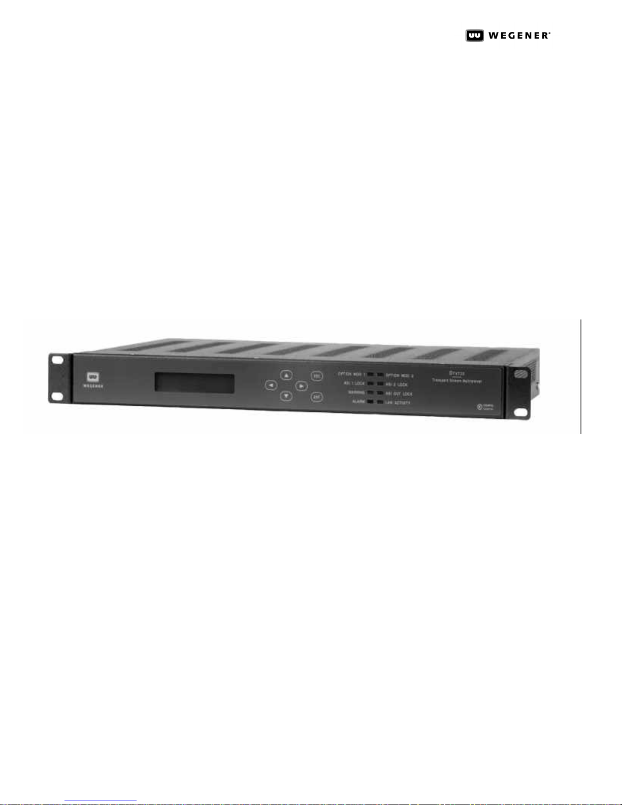
The standard DTV 720 Transport Stream Multiplexer (Figure 1.1) receives up to two ASI
input MPEG Transport streams and provides two identical ASI output streams for
connection to cable system transmission equipment. The input Transport streams are
multiplexed, and programs may be remapped or selected for removal from the output
stream.
The DTV 720 has two input option slots that can increase the number of input streams to
four. The options available are two ATSC 8VSB broadcast demodulators or an additional
single ASI input option that has two ASI input MPEG Transport stream inputs. The DTV
720 has an optional output slot available for either a DHEI output stream or a Gigabit
MPST output stream.
Physical
Description
The DTV 720 is housed in a standard, rack-mountable chassis. Its front panel provides a
user interface through an LCD, eight LEDs, and six push buttons (see section 3.3 DTV720
Controls and Indicators on page26).The rear panel holds the ports that allow
connection to power, incoming signal, and peripheral devices.
Figure 1.1 DTV 720 Transport Stream Multiplexer
Features The DTV 720 has the following features:
• Two ASI MPEG Transport Stream Inputs (BNC Connectors)
• Two Duplicate ASI MPEG Transport Stream Outputs (BNC Connectors),
• Up to Two ATSC 8VSB RF Input Modules (F Connector)
• DHEI Output Transport Stream Module (Optional)
• Gigabit Output Transport Stram Module (Optional)
• Time Re-stamping of PCR, PTS, and DTS Information
• User Selection of Input Programs To Be Included in the Output Stream
• User Selection of Output Program Numbers and Audio Mode
• One Ethernet TCP/IP Control Interface (RJ-45 connector)
800043-01 Rev. C 2 www.wegener.com
Page 9
DTV 720 USER’S MANUAL
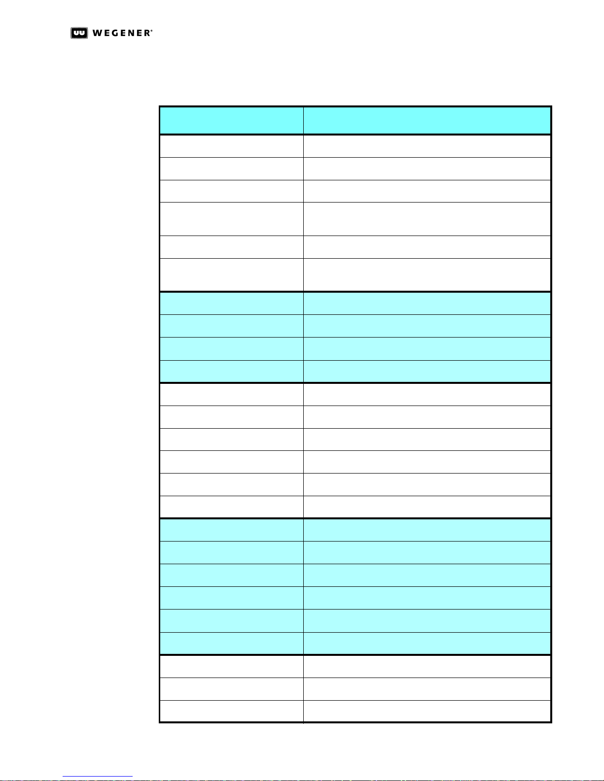
1.3 DTV 720 Specifications
Table 1.1: DTV 720 Technical Specifications
Characteristic Specification
Environmental
Use Indoor
Altitude Up to 2000 meters
Temperature Range 0°C to +50°C Operating
-20°C to +70°C Storage
Cooling Internal fan
Relative Humidity (max.) 80% for temperatures up to 31°C decreasing linearly to 50%
relative humidity at 40°C.
Input AC Power
Voltage 90 to 132 Vac and 175 to 264 Vac
Frequency 50/60 Hz ± 2%
Power Consumption 43 Watt
Mechanical
Height 1 std. RU (1.75 inches nominal) (44.5 mm)
Width EIA std. 19-inch mounting (482.6 mm)
Depth 13.5 inches (342.9 mm)
Weight 10.5 lb (4.81 kg)
Expansion Module Slots 3 - each 2.5"W x 1.375"H x 7"D on rear panel
Serial Port
Standard RS-232
Handshaking None
Service Software download
Baud Rates 115.2 kbps
Formatting 8 data-bits, 1 start, 1 stop-bit, no parity
Ethernet Port
Physical Layer 10BaseT/100BaseT (twisted pair) on RJ-45 jack
Media Access and Link Layer Per IEEE 802.3 (Ethernet)
www.wegener.com 3 800043-01 Rev. C
Page 10
DTV 720 USER’S MANUAL
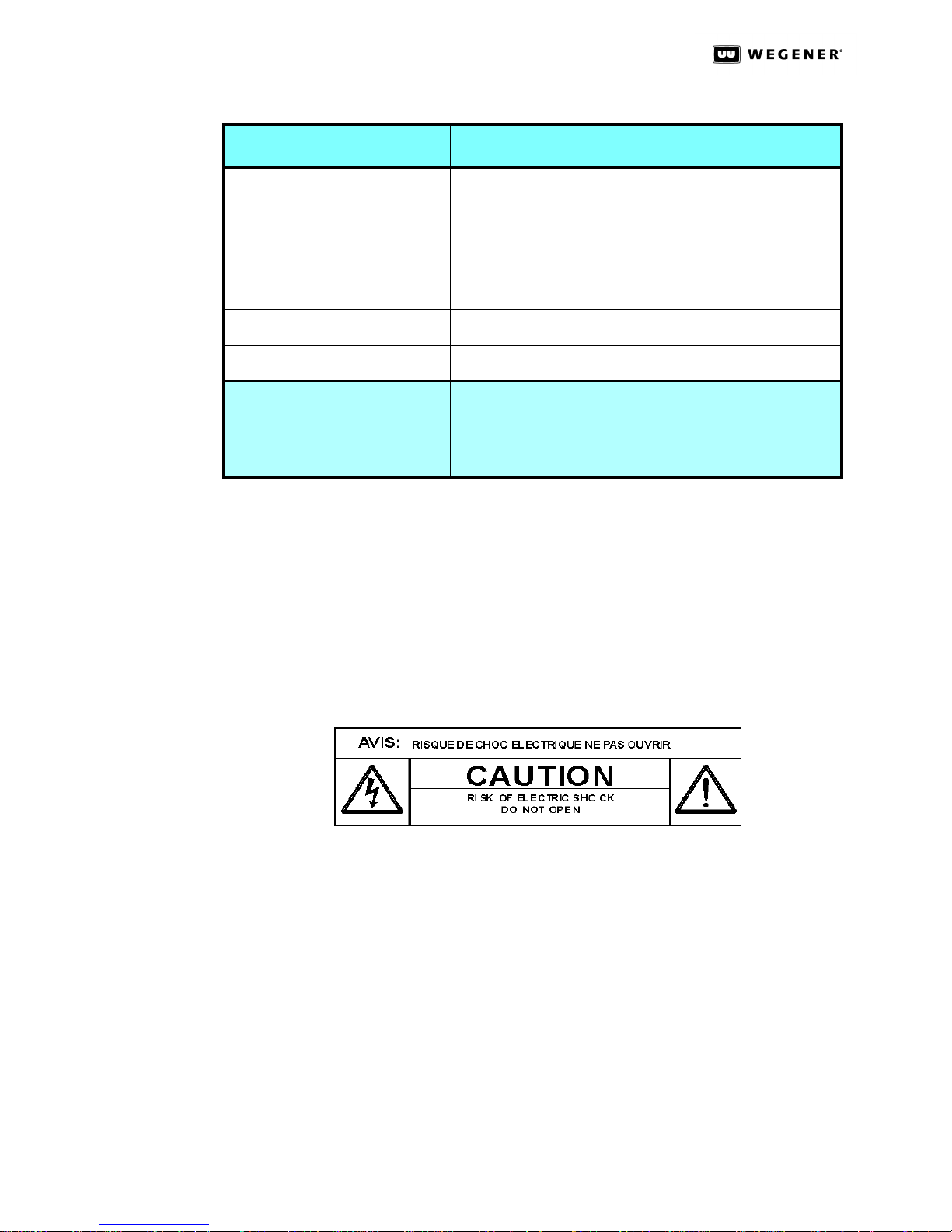
Alarm and Warning Relays
Alarm Function Contact closure for main power off, loss of expected input
Warning Function Contact closure for main power off, oversubscription, or input
Type Form C, Normally Open and Normally Closed
Rating 30Vdc open circuit, 500 mA max current closed
Expansion Module Slot Allowable Expansion Modules:
Table 1.1: DTV 720 Technical Specifications
Characteristic Specification
signal
stream with more than 1 error per 10 seconds
• DHEI Transport Stream Output
• Gigabit Transport Stream Output
• 8VSB Tuner Module
1.4 Safety Summary
The DTV 720 is designed for safe use with few special precautions required of the user.
The following items are basic precautions to use when installing and working with your
DTV 720:
Do not open the DTV 720’s chassis cover.
800043-01 Rev. C 4 www.wegener.com
Page 11
1.5 Glossary of Terms and Abbreviations
Table 1.2: Glossary of Terms
Term Definition
AC Alternating current
Alarm A condition or notification of a condition that prevents your DTV 720 from
performing properly
DTV 720 USER’S MANUAL
Application Software
ASI (or DVB-ASI) An “asynchronous” bit-serial physical interface for Transport Streams.
ATSC Advanced Television Systems Committee - sets standards for standard defi-
Boot loader Software residing in non-writable zone of flash which executes at unit reset.
Carrier An RF signal containing coded audio, video, and/or other data
DVB-ASI see ASI
EIA Electronic Industries Association
Ethernet The widely-used LAN technology specified by IEEE standard 802.3
Flash Memory A memory dedicated to storing the unit’s software and an image of some
The main host software which sets up the unit hardware, runs the process of
acquiring Transport Stream sources, sets up and monitors the multiplexing
processes, monitors unit operations, and provides interfaces with the network and local users.
Transmitting and receiving functions are designed such that the time relationships between all packets and their timing references are unchanged.
nition and high definition television in the U.S. Sometimes used to mean the
HDTV standards.
hardware programming code.
IEEE Institute of Electrical and Electronics Engineers
LAN Local area network. Your DTV 720 may be connected to an Ethernet LAN.
LCD Liquid crystal display. The front-panel text screen on your DTV 720 is a liq-
LED Light-emitting diode. The front-panel indicator lights on your DTV 720 are
Mbps, kbps Megabits per second or kilobits per second - units of data transport rate.
MPEG Moving Picture Experts Group - refers to the method of video compression
NVRAM Non-volatile memory. A memory dedicated to storing the unit’s setup param-
www.wegener.com 5 800043-01 Rev. C
uid crystal display.
LEDs.
established by this group.
eters. This memory retains its contents through power outages.
Page 12
DTV 720 USER’S MANUAL
PAT Program Allocation Table. Master table which identifies all the Programs in
PCR Program Clock Reference. Time-base signal used to synchronize transport
PID Packet Identifier. The unique Transport Stream packet identifier assigned to
PMT Program Map Table. Table for a given Program identifying all the PIDs for its
Program In the MPEG hierarchy, a grouping of related audio, video, or generic data
PSI Tables Program-Specific Information Tables. A group of information-bearing tables,
Table 1.2: Glossary of Terms
Term Definition
the Transport Stream. It associates Program numbers to the PIDs bearing
the associated Program’s PMT.
stream data.
each constituent data stream within the Transport Stream. Also, in this document, “PID” is used to designate the stream itself.
PCR, video, audio, and user data streams.
PIDs sharing a common PCR time base and (usually) sharing a common
schedule. See PMT.
each borne by well-known PIDs, regularly transmitted in the Transport
Stream. See also “PAT” and “PMT”. Also, ISO 13818-1 gives a thorough
description of these and other Tables.
PSIP Program and System Information Protocol - a method for transporting digital
television system information and electronic program guide data.
RAM Random access memory. A general term for all memory volatile memory
types out of which application software executes and into which its variables, state information, and messages are stored. RAM is also used to
designate the volatile storage used by the Transport Demux and decompression devices.
RF Radio frequency
TMRA Maximum Recommended Ambient Temperature, the highest operating tem-
perature for which the unit is rated
Transport Stream
(or MPEG Transport
Stream)
Warning A condition or notification of a condition that may compromise the proper
A multiplex of several data streams, each of which is borne in Transport
packets, 188-byte blocks containing a sync word, header information
(including a PID), and payload data. This multiplex includes PSI data tables,
Programs, and padding in the form of null packets.
performance of your DTV 720
800043-01 Rev. C 6 www.wegener.com
Page 13

Chapter 2 Installation
This chapter provides instructions on unpacking, mounting, and connecting the DTV 720,
as well as connector information including detailed pinouts.
2.1 Unpacking and Inspection
Carefully unpack the unit and its ac power cord and inspect for obvious signs of physical
damage that might have occurred during shipment. Any damage claims must be reported
to the carrier immediately. Be sure to check the package contents carefully for important
documents and materials.
NOTE: Please save the packing materials and original shipping containers in case you must later
return the unit for repair. Packing these units in other containers in such a way that they are
damaged will void your warranty.
2.2 Location and Mounting
The DTV 720 should be located indoors and may be mounted in a standard, 19-inch equipment rack within one standard RU.
DTV 720 USER’S MANUAL
WARNING
This is a Class A product. In a domestic environment this product may cause radio
interference for which the user may need to take mitigating action.
DANGER
To avoid damage to this and other equipment, or personal injury, the following items
should be strictly observed.
Elevated Operating Ambient
When equipment is installed in a closed or multi-unit rack assembly, the operating ambient
of the rack environment may be greater than the room ambient. Therefore, consideration
should be given to the ambient air temperature within the rack, and not just inside the
room, when deciding if the maximum recommended ambient operating temperature
(T
) is being met or exceeded.
MRA
Reduced Air Flow
Equipment should be installed such that airflow required for safe operation of the equipment is not compromised.
Mechanical Loading
Mounting of the equipment in a rack should be such that a hazardous condition is not produced by uneven loading. This unit is not very heavy, but total rack loading must be considered. Also, do not rest any unsupported equipment on your DTV 720.
www.wegener.com 7 800043-01 Rev. C
Page 14

DTV 720 USER’S MANUAL
Circuit Overloading
Consideration should be given to the connection of the equipment to the supply circuit and
the effect that overloading of circuits could have on overcurrent protection and supply wiring. Ensure that the total rack or breaker power consumption does not exceed the limits of
the ac branch circuit. Appropriate consideration of equipment ratings should be used
when addressing this concern.
Reliable Earthing
Reliable earthing of rack-mounted equipment should be maintained. Particular attention
should be given to supply connections other than direct connections to the branch circuit
(use of power strips, chassis ground lugs, etc.).
Rack
Mounting
The DTV 720 is sized to fit in an EIA-standard, 19-inch-wide equipment rack.
a. First install angle brackets or cross-supports capable of supporting both the unit
and its connecting cables. Screw or bolt the supports securely to the equipment
rack.
b. Place the DTV 720 on its supports and use four anchor screws or bolts and nuts to
secure the unit’s front brackets to the rack.
c. Connect the chassis grounding screw to an earth ground before connecting the
power cord to the unit.
WARNING
The front brackets must be secured to the rack. If front brackets are left unsecured, the
unit may shift forward and fall from the rack during installation or operation. Failure to
secure the front brackets may result in personal injury and/or damage to the equipment.
WARNING
Locate the DTV 720 and its cables to avoid impacts, spills, and pulling cables and to
ensure sufficient air flow. Failure to locate the DTV 720 in a proper environment may result
in damage to the equipment.
800043-01 Rev.C 8 www.wegener.com
Page 15
2.3 DTV 720 Connections
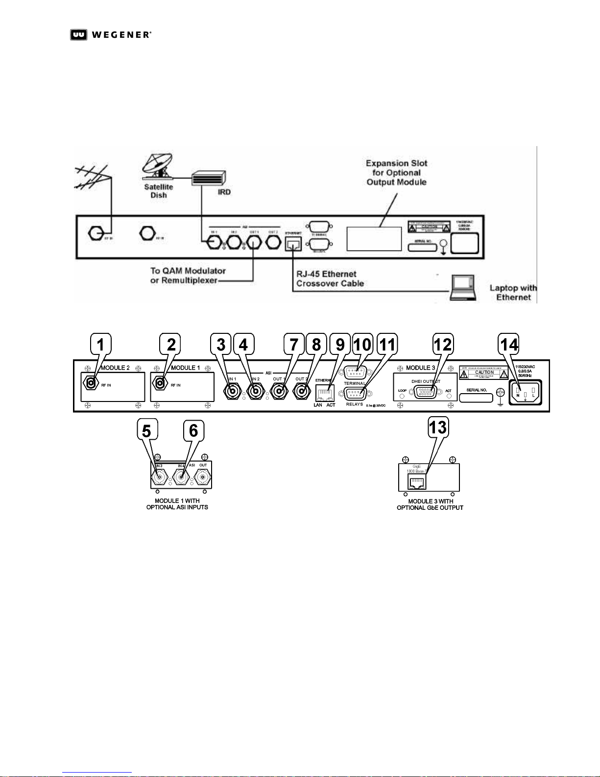
Figure 2.1: DTV 720 System Setup below shows placement of the DTV 720 in a typical cable
headend. Figure 2.2: DTV 720 Rear Panel Connections illustrates details of the DTV 720’s
rear panel.
Figure 2.1: DTV 720 System Setup
Figure 2.2: DTV 720 Rear Panel Connections
DTV 720 USER’S MANUAL
Before applying power, make the following connections to the DTV 720. (See Table2.1 for
the connector details.)
a. Connect the chassis grounding screw to an earth ground before connecting the
power cord to the unit.
b. Connect the 8VSB ATSC signal from your antenna to the RF IN port (1 and/or 2 if
present) and/or ASI input signals to the ASI IN 1 and ASI IN 2 ports (3 and 4).
c. If the Module 1 option with additional ASI input ports is installed, connect the ASI
IN 3 and ASI IN 4 ports (5 and 6, if present).
d. Connect downstream transmission or monitoring equipment to the ASI OUT 1 and
ASI OUT 2 ports (7 and 8) if present and desired.
e. Connect your LAN line to the DTV 720’s Ethernet port (9).
f. If desired, connect the Relays port (11) to your equipment to provide contact
closures during alarms and warnings.
www.wegener.com 9 800043-01 Rev. C
Page 16
DTV 720 USER’S MANUAL
g. Connect the DHEI output connector (12, if present) to the cable headend DHEI
h. Connect the GbE Output connector (13 if present) to an IP/Ethernet infrastructure.
i. Finally, connect the supplied ac power cord to the DTV 720’s IEC receptacle (14)
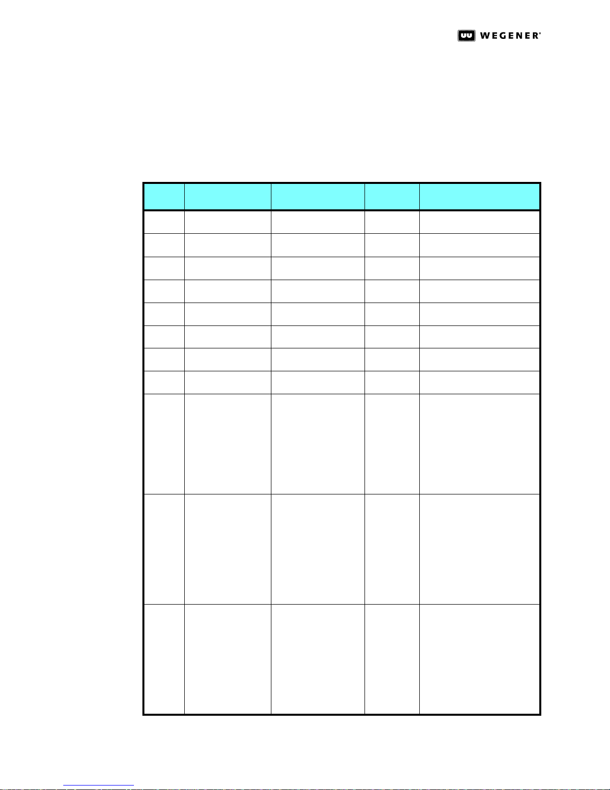
Item Designation Connector Type Pin No. Signal Name
1 RF In 1 Female type-F RF IN 1
2 RF In 2 Ffemale type-F RF IN 2
3 ASI In 1 Female BNC ASI IN 1
4 ASI In 2 Female BNC ASI IN 2
5 ASI In 3 Female BNC ASI IN 3
equipment using a 15-pin to 26-pin DHEI cable. Be sure to use the correct cable
depending upon whether you are connecting to the DHEI Expansion Input or the
DHEI Expansion Output connector.
Be sure to use good-quality CAT5E cable for this connection.
and to a 90-to-132 Vac power source.
Table 2.1: DTV 720 Connector Details
6 ASI In 4 Female BNC ASI IN 4
7 ASI Out 1 Female BNC ASI OUT 1
8 ASI Out 2 Female BNC ASI OUT 2
9 Ethernet LAN Female RJ-45 1
10 Serial Async I/O DB-9 1
11 Alarm/Warning
Relays
Male DB-9 1
2
3
4
5
6
7
8
2
3
4
5
6
7
8
9
2
3
4
5
6
7
8
9
EN OUT +
EN OUT EN IN +
NC
NC
EN IN NC
NC
DCD (+5V, 4.7 kΩ)
RxD (output)
TxD (input)
NC
GND
DSR (+5V, 4.7 kΩ)
NC
CTS (+5V, 4.7 kΩ)
RI (+5V, 33 Ω)
Not used
Not used
WARNING COMMON
ALARM COMMON
GND
OPEN ON WARNING
OPEN ON ALARM
CLOSE ON WARNING
CLOSE ON ALARM
800043-01 Rev.C 10 www.wegener.com
Page 17
DTV 720 USER’S MANUAL
Table 2.1: DTV 720 Connector Details
Item Designation Connector Type Pin No. Signal Name
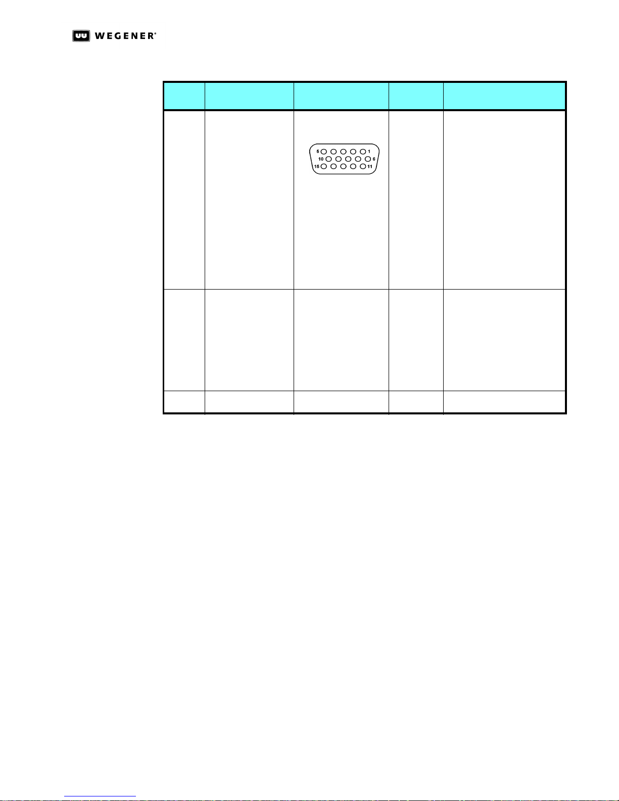
12 DHEI Out D subminiature 15-pin 1
2
3
4
5
6
7
8
9
10
11
12
13
14
15
13 GBE Out Female RJ-45 1
2
3
4
5
6
7
8
14 115/230 Vac Power Male IEC receptacle AC LINE IN
RESERVED
RESERVED
RESERVED
RESERVED
SIGND
SENSEOL
PSYNCO+
PDATAO+
PCLKO+
REFCLKO+
SENSEOR
PSYNCOPDATAOPCLKOREFCLKO-
MDI0+
MDI0 MDI1+
MDI1MDI2+
MDI2 MDI3+
MDI3 -
Ethernet An Ethernet 10BaseT/100BaseT port is included and is the primary user interface using
an HTML browser-based interface. The unit has an URL which is assigned via the front
panel. The “home” page is then accessed by users via the Ethernet port. From this page,
the desired channel selections may be performed and status monitored.
Terminal I/O The Terminal serial port is configured to 115.2k, N, 8, 1. The Terminal device is used for
command and control of the DTV 720. This I/O is a basic, VT100-like emulation. User input
text strings terminated in carriage-returns prompt all I/O. The terminal should be set to
local echo ON because the DTV 720 only echoes a carriage-return/linefeed and then a ‘>’
prompt after entry of a command-line terminated in carriage-return.
www.wegener.com 11 800043-01 Rev. C
Page 18

DTV 720 USER’S MANUAL
This page intentionally left blank.
800043-01 Rev.C 12 www.wegener.com
Page 19

Chapter 3 Operation
3.1 Operation Overview
This chapter contains detailed operating instructions for the DTV 720 The following sections address:
• Ethernet/Web Browser Control
• DTV 720 Controls and Indicators
• Front-Panel Operation
• Initialization
• Transport Stream Processing
• Alarm and Warning System
• Software Downloads
Local user control is from a LAN via RJ-45 Ethernet or the front-panel LCD/keypad. All
settings may be presumed to be retained through power cycling unless otherwise specified. This means that they are still in effect through resets, whether by power outage, commanded reset, or failure-recovery resets.
DTV 720 USER’S MANUAL
3.2 Ethernet/Web Browser Control
The DTV 720’s primary user interface is from a web browser using the rear-panel Ethernet
LAN connection. An HTML script interface allows a user to control and monitor the unit
using a standard web browser. Each unit contains a user-defined quad URL address, subnet mask, and gateway address (See Table 3.1: DTV 720 IP Setup.)
There are two basic methods of using the Ethernet connection – with a directly connected
PC or with a PC connected through a LAN.
Directly
Connected
PC
For control from a local PC, attach the DTV 720’s Ethernet port to the Ethernet network
connector on the PC using a crossover RJ-45 cable (8 pins).
Before using this Ethernet connection, the appropriate IP address, netmask, and gateway
must be selected via the front-panel interface.
Perform the DTV 720 IP Setup as shown in Table3.1 and the PC IP Setup as shown in
Table3.2:
Table 3.1: DTV 720 IP Setup
Parameter Setting
IP Address 172.016.100.001
www.wegener.com 13 800043-01 Rev. C
Subnet Mask 255.255.000.000
Page 20

DTV 720 USER’S MANUAL
Table 3.2: PC IP Setup
Parameter Setting
IP Address 172.016.100.020
Netmask 255.255.000.000
Gateway 000.000.000.000
LAN
Connection
Using the
Web Browser
For LAN connection, attach the DTV 720’s Ethernet port to the LAN using a normal,
straight-through, RJ-45 cable. Set the DTV 720 IP Address, Netmask, and Gateway as
directed by your network administrator. Use any PC on the LAN to connect to the DTV 720
using the web browser instructions below.
NOTE: Each DTV 720 unit on the network must have a unique address.
To begin DTV 720 monitor and control functions from a PC or LAN connection:
a. Open the current internet browser of your choice from the local PC or computer on
the LAN attached to your DTV 720.
b. Set the browser's address field to http://nnn.nnn.nnn.nnn where nnn.nnn.nnn.nnn
is the IP address of the unit to be controlled (set from the DTV 720’s front-panel, IP
Address screen).
NOTE: For IP addresses which include subfields with leading zeros, you must omit those
zeros when entering the address in your browser. For example, IP address
128.092.050.004 must be entered as 128.92.50.4.
The DTV 720 Control and Status page will appear. You may select the Stream Info, Unit
Configuration, Alarm Config, Pidsets Config, Module Config, or Q&A/Help pages at any time
by clicking the appropriate tab for each at the top of the screen.
Normally you will first select the Control & Status page to select the input, output, control,
and COMPEL characteristics. Use the Pidsets Config page to select programs to be
included in the output (by either channel name or program number), assign new program
numbers if desired, change the major/minor channel number, change the channel name,
and select the audio to be included in each program’s output. Next, select the Stream Info
page to verify that the input and output data are configured as intended
Finally, you may select the Unit Configuration screen to save the configuration. If you have
multiple configurations that you use from time to time, you may now set them up using the
same steps as above. After the initial setup, it will be easy to select various stored configurations from the Unit Configuration screen. The following paragraphs give a detailed
description of each screen.
800043-01 Rev. C 14 www.wegener.com
Page 21
DTV 720 USER’S MANUAL
Control and
Status Page
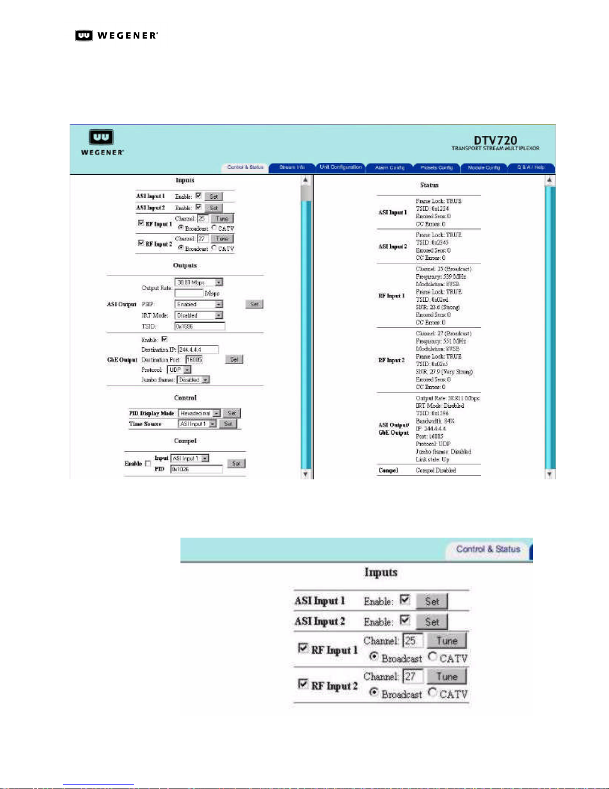
The left side of this page is used for control selections and the right side gives input and
output status. The serial number of the DTV 720 unit and the version number of the application software installed in the unit are shown at the top of the left side.
Figure 3.1: DTV 720 Control and Status Page
Inputs
www.wegener.com 15 800043-01 Rev. C
Figure 3.2: DTV 720 Control & Status Inputs Section
Page 22
DTV 720 USER’S MANUAL
The Inputs section (on the left side) allows setting of the two ASI inputs and RF inputs if
available. If the ASI inputs are used, select the Enable check box and click the Set button
for each one that is used. Similarly, select the Enable checkbox for each RF input that is
used, set the channel number, click the radio button to select either Broadcast or CATV,
then click the Tune button. If the optional, dual ASI Input Module is used rather than the
RF Input Modules, then set them up in the same manner as the included ASI Inputs.
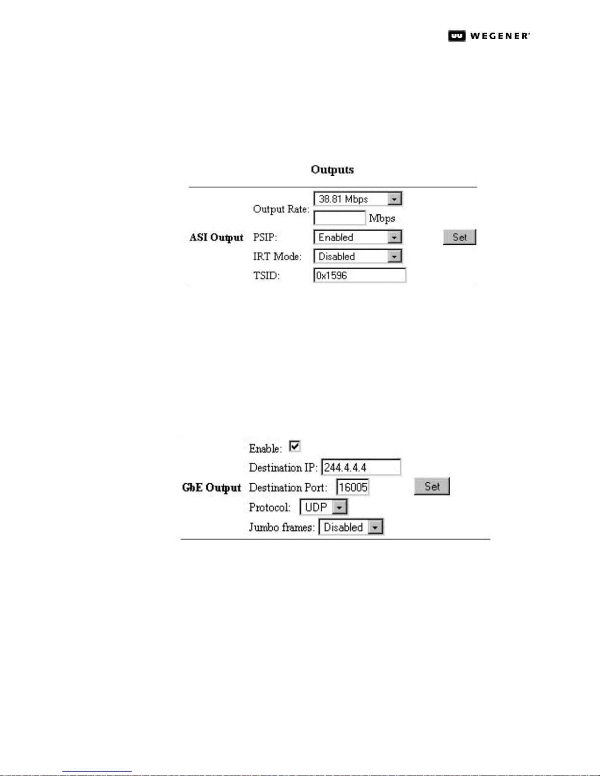
Figure 3.3: DTV 720 Control & Status Page ASI Output Section
The ASI Output section allows the user to set the Output Rate; Enable/Disable output PSIP
data, Enable/Disable the IRT Mode; and set the output TSID number. The output data rate
may be set to 19.39 Mbps, 26.97 Mbps (64 QAM), 38.81 Mbps (256 QAM), or to a custom
rate between 2.5 Mbps and 70 Mbps. The PSIP Enabled/Disabled box allows PSIP data to be
included in the output stream. The IRT Mode box allows the user to Enable/Disable the
functions needed for use in systems with the Motorola IRT product. This is normally set to
OFF. (Refer to IRT Mode on page36 for more details.) The output TSID number may be set
to a four-digit hexadecimal number. You will normally use the TSID of the major program
included in the multiplex, which may be found on the Status (right) side of the page.
Figure 3.4: DTV 720 Control & Status Page GbE Output Section
The GbE Output section (if the GbE module is installed) allows the user to Enable GbE
output; assign a Destination IP address and Destination Port number to the output
stream; set the Protocol; and enable Jumbo packet frames. The output date rate and
content of the GbE output is identical to the ASI output stream as configured under
the Pidset Config page. The content of the GbE output is assigned to one IP address
and one port number; this makes the GbE output stream a Multi-Program Transport
Stream (MPTS) service. The output Protocol can be configured as either UDP or RTP.
The standard payload packet frame size is 1.5Kbps, when Jumbo frames is enabled
the payload packet size is set to 9Kbps.
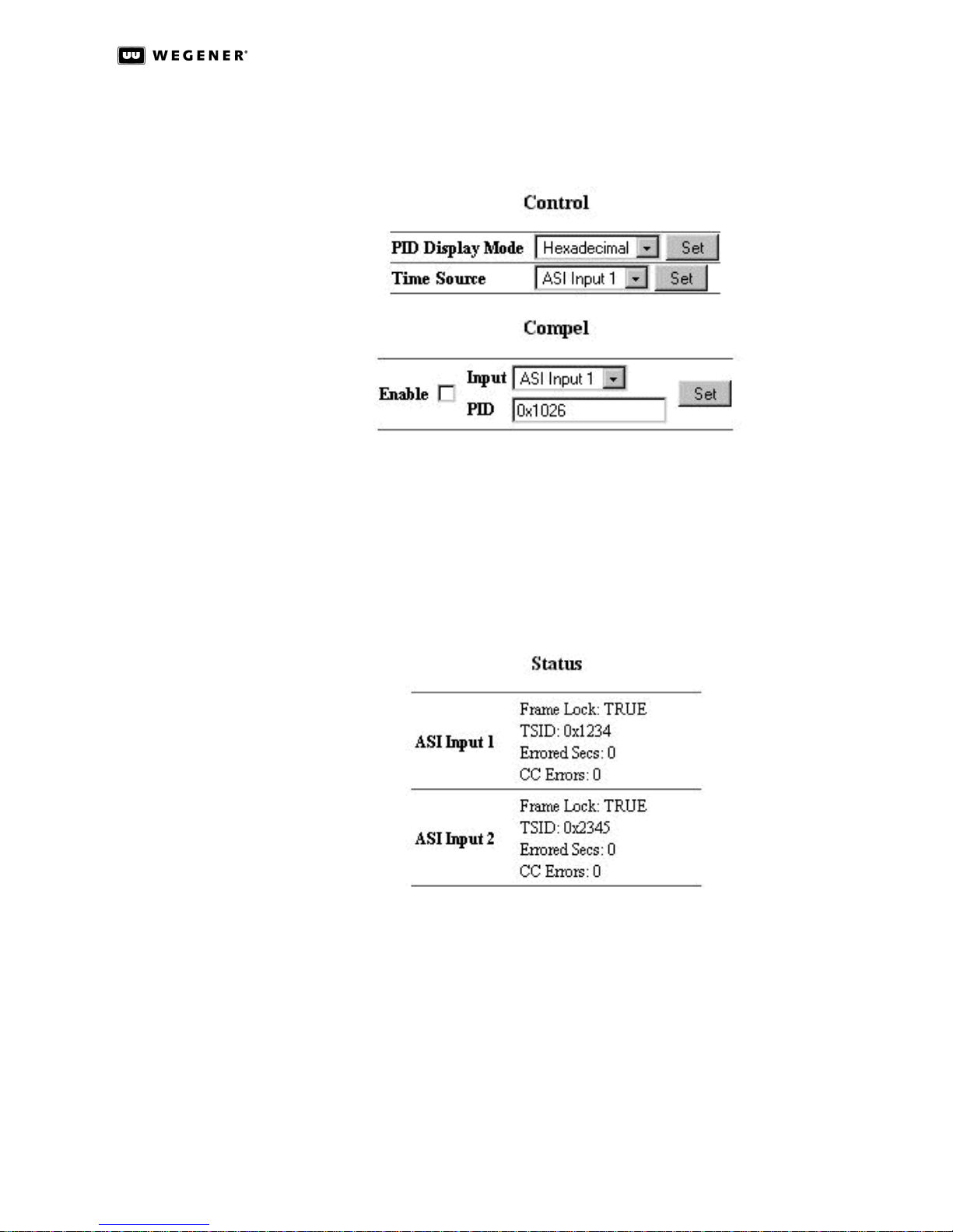
In the Control section, the PID Display Mode and Time Source may be selected. The PID
Display Mode is used to select whether the PID numbers on all the screens are displayed
in decimal or hexadecimal format. (Note that program numbers are always displayed in
800043-01 Rev. C 16 www.wegener.com
Page 23
DTV 720 USER’S MANUAL
decimal format regardless of this selection.) Because up to four independent input
sources may be present, the Time Source selection box is used to select which of these
inputs is used to set the clock in the unit.
Figure 3.5: DTV 720 Control & Status Page Control Sections
The Compel section is for systems that use Wegener's COMPEL Control. After you select
the input stream and the PID of the stream containing the COMPEL commands, use the
Enable checkbox and the Set button to set the stream and PID information.
Status
The Status section (on the right side) provides the unit’s input and output signal status.
Figure 3.6: DTV 720 Control & Status Page ASI Input Status
The ASI Input entries indicate whether or not the ASI Inputs show frame lock. Frame lock
normally indicates a signal good enough for reception with few or no errors. When frame
lock is achieved, the TSID of the stream is shown together with the errored seconds and
Continuity Count (CC) errors. Errored Secs indicates the number of seconds in which
errors occurred in the input stream since the last time the error counter was cleared. CC
errors indicate the the number of errors detected where packet discontinuities occurred.
These counters may be cleared by clicking the word Clear.
www.wegener.com 17 800043-01 Rev. C
Page 24
DTV 720 USER’S MANUAL
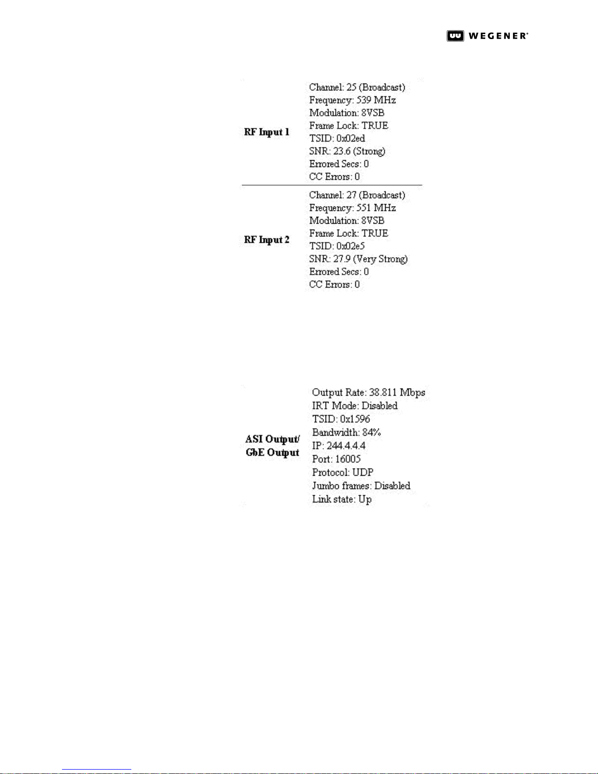
For each RF input, the RF Input entries show the Channel number (the actual RF broadcast channel, not the legacy analog channel number of the station); the Frequency; the
Modulation type (8VSB, 64QAM, or 256QAM); the Frame Lock status; the TSID; the SNR
(signal-to-noise ratio); the Errored Secs; and the CC Errors.
Figure 3.7: DTV 720 Control & Status Page RF Input Status
Figure 3.8: DTV 720 Control & Status Page ASI/GbE Output Status
ASI Output lists the ASI stream’s data transport Output Rate; IRT Mode status, TSID, and
Bandwidth utilization. Bandwidth indicates the percentage of the output Transport
Stream’s data rate that is occupied with actual data (not null packets).This indicator may
be used to determine whether additional programs may be enabled for output.
If the GbE Module is installed, the list will include the IP address; Port number; Protocol
type; Jumbo frames status; and output Link state.
If Compel is present and enabled, the Compel entry under Status indicates the Compel
source stream and the Compel PID. These should confirm the selections made under Com-
pel on the left side of the page. If Compel is not present and enabled, the entry will simply
show Disabled.
800043-01 Rev. C 18 www.wegener.com
Page 25
DTV 720 USER’S MANUAL
Stream
Information
Page
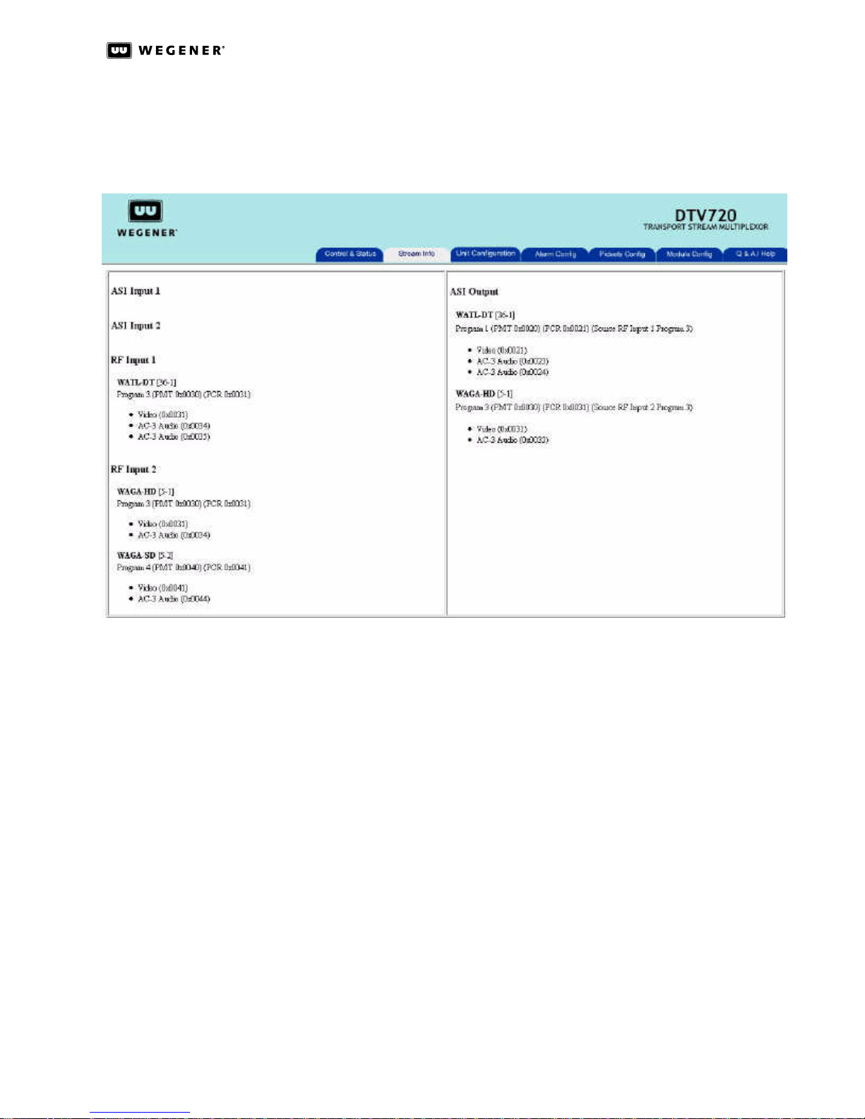
The Stream Information page (see Figure3.9) gives detailed information on all input
streams and the output stream. This is for reference only. No selections may be made on
this page. The left side shows input information and the right side shows output information.
Figure 3.9: DTV 720 Stream Information Page
Unit
Configuration
Page
Input information begins with ASI Input 1 followed by ASI Input 2, RF Input 1, and RF Input 2.
All input streams are shown whether or not they are selected for the output. Information
provided for each active input includes the Pogram Short Name; Major and Minor channel
numbers; Program Number with PMT and PCR PID locations indicated; and a list of all
referenced streams (video, audio, and data) with their PID numbers. Any PIDs present
that are not referenced are shown as Ghost PIDs.
Output information provides the same information as the Input side plus the input source
of each output program.
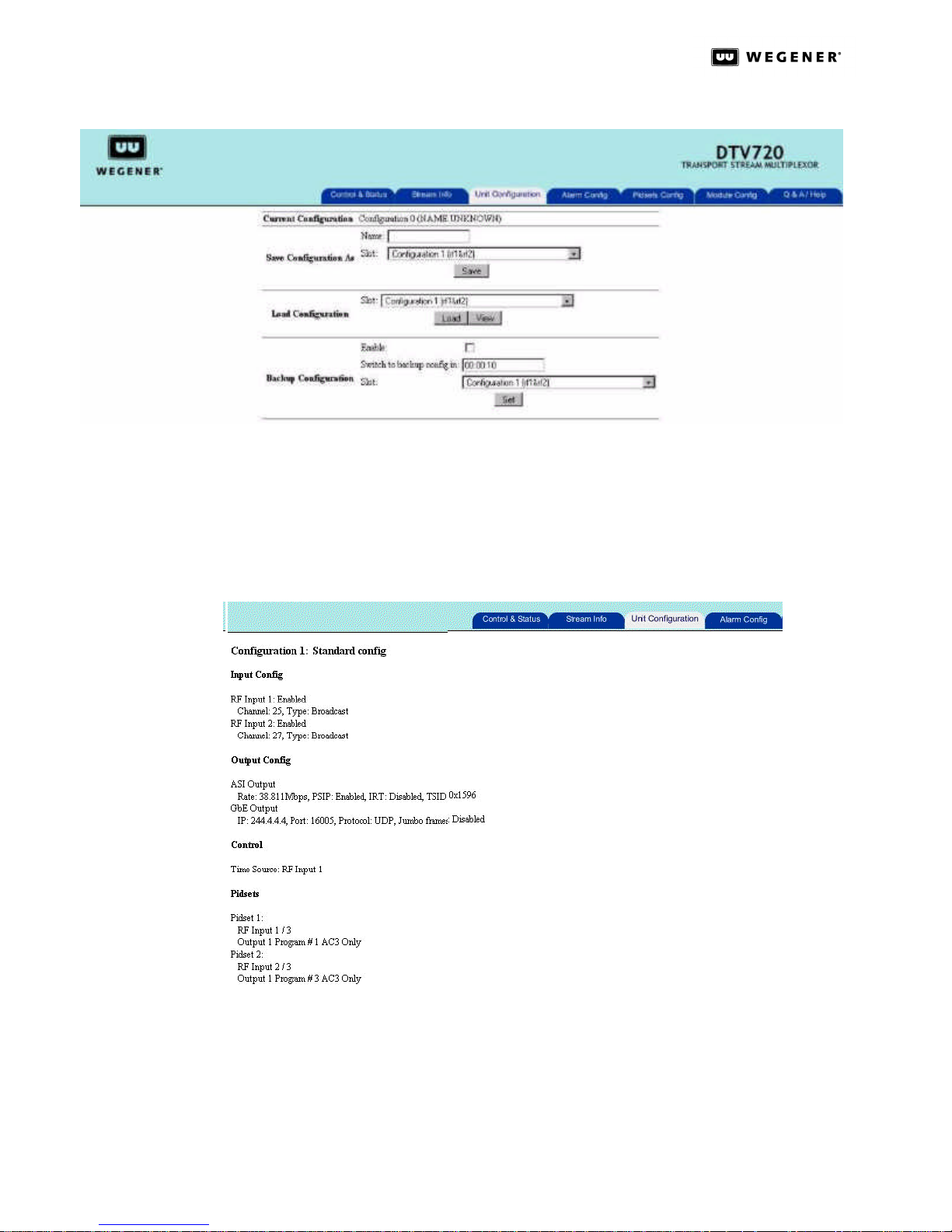
The Unit Configuration Page, shown in Figure 3.10, allows the multiplex configuration to be
stored with a user-selected name. A stored configuration may be loaded at any time to
rapidly change the configuration of the unit. Using Unit Configuration, a single backup unit
could be loaded with the configurations of several on-line units. Then, in the unusual case
of failure of an on-line unit, the backup could be installed with the correct unit configuration
already loaded. With up to twenty characters allowed for each configuration name, highly
descriptive naming may be used.
www.wegener.com 19 800043-01 Rev. C
Page 26
DTV 720 USER’S MANUAL
In the Load Configuration section there is a View button that allows the user to view the
settings for a stored configuration. Select a configuration from the drop down list and click
the View button. To exit the View Configuration mode, click on any tab on the top part of
the Web page. The settings that are display in the View mode in Figure 3.11 are the stored
settings for the Input and Output configurations, Control settings, and PIDSET configurations.
Figure 3.10: DTV 720 Unit Configuration Page
Figure 3.11: DTV 720 Unit Configuration View Mode
The Backup Configuration section allows the user to set up the unit to automatically switch
to a backup configuration in the event of an Alarm condition. Once a Backup Configuration
has been enabled, when an Alarm condition occurs, the unit will switch to the user-defined
backup configuration after the specified delay time selected in the Switch to backup config
in box. Wegener recommends that the switch delay time be set so that a very brief outage
800043-01 Rev. C 20 www.wegener.com
Page 27
DTV 720 USER’S MANUAL
will not cause a switch. The Alarm condition that will cause such a switch is defined by thesetup on the Alarm Configuration Page. Any of the 21 conditions listed on this page will
cause a switch if that condition is configured as an Alarm.
Once the DTV 720 unit has switched to a Backup Configuration, a warning will be displayed
on its front panel LCD screen and on the Control & Status page, indicating that the unit is
in a Backup Configuration mode. The unit will not automatically recover from this switch. It
is up to the user to verify that the condition that caused the switch has cleared. Then the
unit can be manually switched back to its former configuration.
Alarm Config
Page
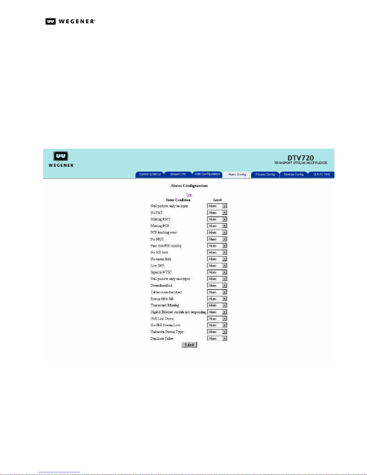
The Alarm Config page allows the user to configure whether an event type will be handled
as an Alarm or Warning condition or whether the event type will be disabled so that no
Alarm or Warning indications will be given for that specific type of event. (See Figure3.12.)
Figure 3.12: DTV 720 Alarm Configuration Page
The Alarm Configuration page should be used in conjunction with the Backup Configura-
tion, under Unit Configuration page, to set up the DTV 720 unit to switch to another config-
uration in the event of a signal source problem. By default, all events are set to be in an
Alarm condition.
Table3.3 on the next page lists all the types of events that can be configured for Alarms or
Warnings, with a brief description of each type of event and what it applies to..
www.wegener.com 21 800043-01 Rev. C
Page 28
DTV 720 USER’S MANUAL
Table 3.3: Event Types Configurable for Alarms, Warnings, or No Indications
Event Description
Null packets only on input Applies to RF, ASI and GbE inputs, when no MPEG stream can be found.
No PAT Applies to RF, ASI and GbE inputs, No PAT PID can be found.
Missing PMT Applies to RF, ASI and GbE inputs, PMT referenced in PAT, but is not in MPEG stream.
Missing PCR Applies to RF, ASI and GbE inputs, PCR referenced in PMT, but is not in MPEG stream.
PCR tracking error Applies to all output ports, PCR value is out of tracking range, NOTE, this event will hap-
pen when new programs are added to output, but should clear after 30 seconds.
No MGT Applies to RF, ASI and GbE inputs, missing MGT is stream.
Pass thru PID missing Applies to RF, ASI and GbE inputs, PID referenced in PMT, but is not in MPEG stream.
No ASI lock Applies to ASI inputs, MPEG sync can not be detected.
No carrier lock Applies to RF inputs, no signal at desired frequency or low signal level.
Low SNR Applies to RF inputs, Mis-aligned antenna or bad cable.
Signal is NTSC Applies to RF inputs, channel setting is analog type.
Null packets only on output Applies to all outputs, no programs selected for output or desired programs not available.
Oversubscribed Applies to all outputs, total payload for selected programs are greater than output data
rate. Video and or audio interruptions are possible.
Tables oversubscribed Applies to all outputs, total payload for selected programs is equal or just greater than
output data rate. PSIP information MAYBE not going out at the correct rate.
Remap table full Applies to all outputs, too many programs are selected for output stream.
Timesource Missing Applies to RF, ASI and GbE inputs, the desired signal for time reference source can not
be found.
Gigabit Ethernet module not
responding
GbE Link Down Applies to optional output GbE module, Output can not detect Destination IP address.
No GbE Stream Lock Applies to optional input GbE module, no input stream can be detected.
Unknown Stream Type Applies to RF, ASI and GbE inputs, stream type code in PMT is not supported.
Duplicate Pidset Applies to RF and ASI inputs, when two programs are selected, one by program number
Applies to optional GbE module, Main processor failed to communicate with module.
and other by PSIP name, are both the same program.
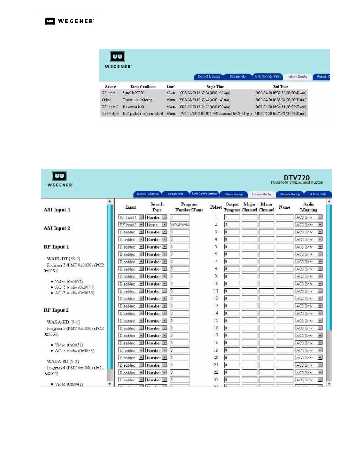
At the top of the Alarm Configuration page is a LOG button. Clicking on the LOG button will
open up the event log, which displays a volatile list of events that have happened since the
last reset or power cycle of the unit. The Alarm Configuration page event log (shown in Fig-
ure 3:13) event information is displayed in 5 columns: Source, Error Condition, Level,
Begin Time, and End Time.
The Alarm Configuration page event log will show the last 300 events. Once the list of
events reaches this limit, the oldest event is removed so that the a new event can be
added to the list and displayed.
800043-01 Rev. C 22 www.wegener.com
Page 29
DTV 720 USER’S MANUAL
Figure 3.13: DTV 720 Alarm Configuration Page Event Log
Pidsets
Config Page
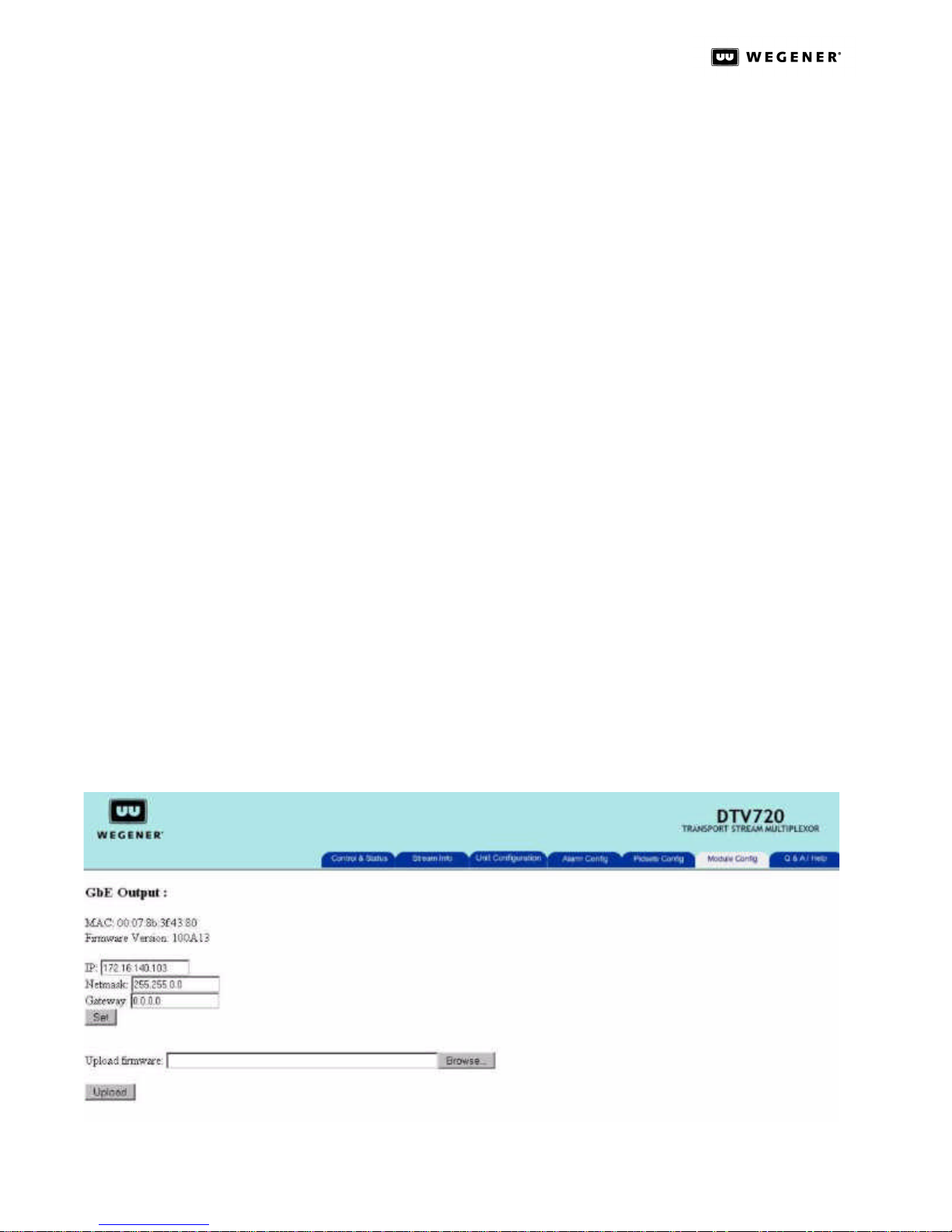
The Pidsets Config page (Figure3.14) allows the selection of programs to be included in
the output. This is the main page for setting up the multiplex.
Figure 3.14: DTV 720 Pidsets Config Page
Up to 32 separate programs may be included in the output. The concept of Pidsets is used
to facilitate creating the multiplex. The Pidsets are numbered from 1 to 32. A Pidset is a
group of 16 PIDs reserved for that Pidset. Each Pidset includes a PMT and PCR PID, as
well as video, audio, and data PIDs. Each Pidset will reassign the input Pidset values to
new PID values, based on which Pidset the program is assigned to.
www.wegener.com 23 800043-01 Rev. C
Page 30
DTV 720 USER’S MANUAL
For example, if a program assigned for output has PIDs that fall in the 0x0030 range, i.e.,
PMT 0x0030, video 0x0031, and this program is assigned to Pidset 1, then the new PIDs
for the program will be reassigned and fall in the new range of 0x0020 for the PMT, and
the video will be at 0x0021. If the same proram was assigned to Pidset 4, the PMT would
be reassigned to 0x0050 and the video would be at 0x0051. This reassignment is shown
on the Stream Info page.
In the example shown, Pidsets 1 and 2 have been activated by selecting the input sources
in their input boxes. The Search Type allows the DTV 720 to search for an input program by
its program number, or by its number, as shown in the example. The user then enters the
appropriate setting in the program number/name box, based on the Search type. (Note
that an input program can only be assigned to a single pidset.) The left side of the page
lists all input programs for easy reference.
Next, each enabled pidset must be assigned a unique output program number. The Major
Channel, Minor Channel, and Name boxes may be used to assign new values to the
selected programs. Leaving these boxes empty allows the original values to be used in
the output. Finally, the Audio selection boxes allow MPEG audio, AC-3 audio, All or None
to be selected for output with each program. You should ensure that the selected audio
format is available on the input program. If you select MPEG only and the input has AC-3
only, you will receive video but no audio for that program. If in doubt, select All. When all
selections have been made, click the Submit button at the bottom of the left side of the
page to activate the selections.
Module
Config page
If you wish to store these selections, return to the Unit Configuration screen and save the
configuration under the desired name.
The Module Configuration page allows the user to use the Web Interface to configure anymodules detected by the DTV 720 unit that can be configured. If the unit does not have
any modules that can be configured, only the following text will be displayed. No config-
urable option modules detected.
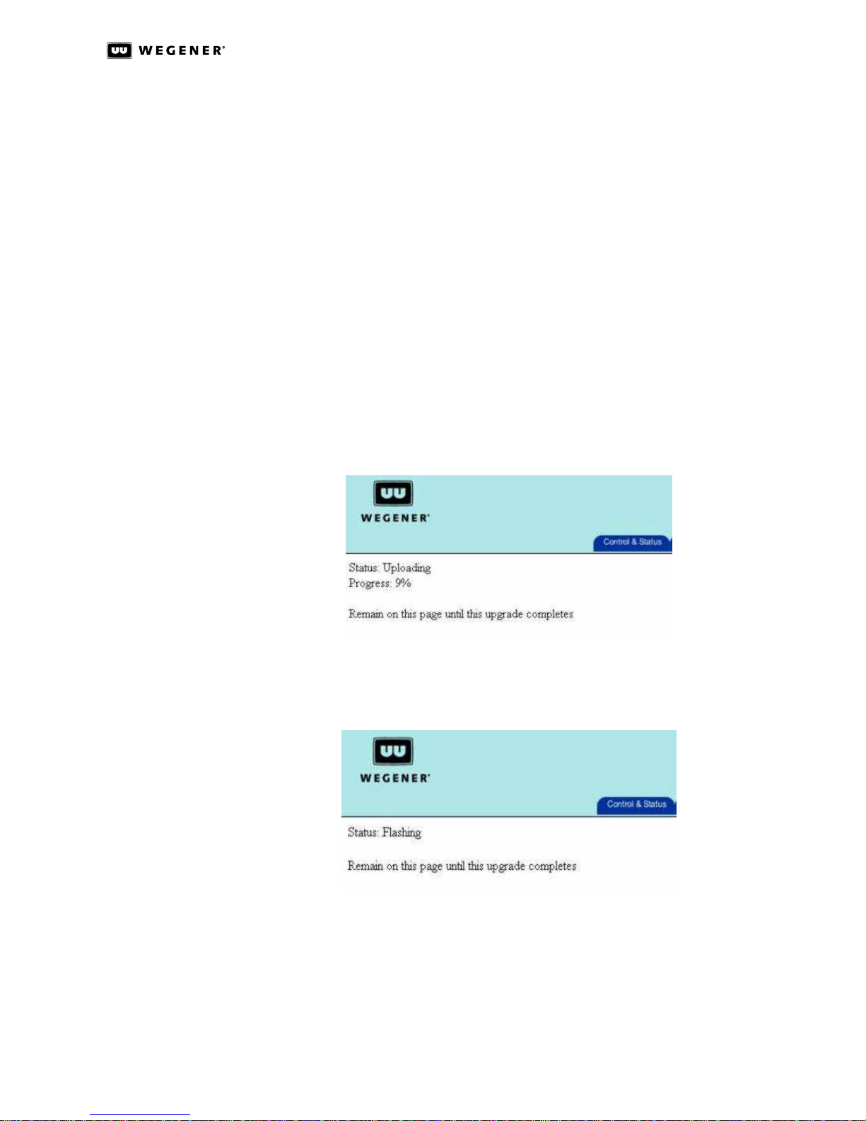
At the current time, only one module supports this mode, and that is the GbE output module.The Module Configuration page showing configuration of a GbE Output Module is
shown in Figure3.15.
Figure 3.15: DTV 720 Module Configuration Page for GbE Output
800043-01 Rev. C 24 www.wegener.com
Page 31
DTV 720 USER’S MANUAL
For the GbE module, the following items are configurable:
• The IP address of the output GbE interface (Required).
• The GbE module's Netmask (Required).
• The GbE module's Gateway address (Optional).
Make or verify the necessary entries, and click the Set button. These settings ensure that
the receiving device will see the DTV 720 output transport stream. Above the settings
fields, this page shows the GbE output MAC address and the current Firmware Version of
the code used in the GbE module.
Below the settings fields, the Upload Firmware field provides the user with a method for
upgrading the firmware used on the GbE output module. To upgrade the GbE firmware:
1. Download and save the GbE firmware upgrade file from http://www.wegener.com/cust-
servdownload.html to your local PC's hard drive.
2. Use the Browse button to find the file, then click the Upload button to start the upgrade.
3. A progress status indication should display the percentage of the code upgrade.
Remain on this page until you are prompted to reboot the unit.
Figure 3.16: DTV 720 Module Config Page Firmware Upload Status
4. The status will go to 100%, then show that the status is Flashing, which means that
the code is being updated on the module.
Figure 3.17: DTV 720 Module Config Page Firmware Flashing Status
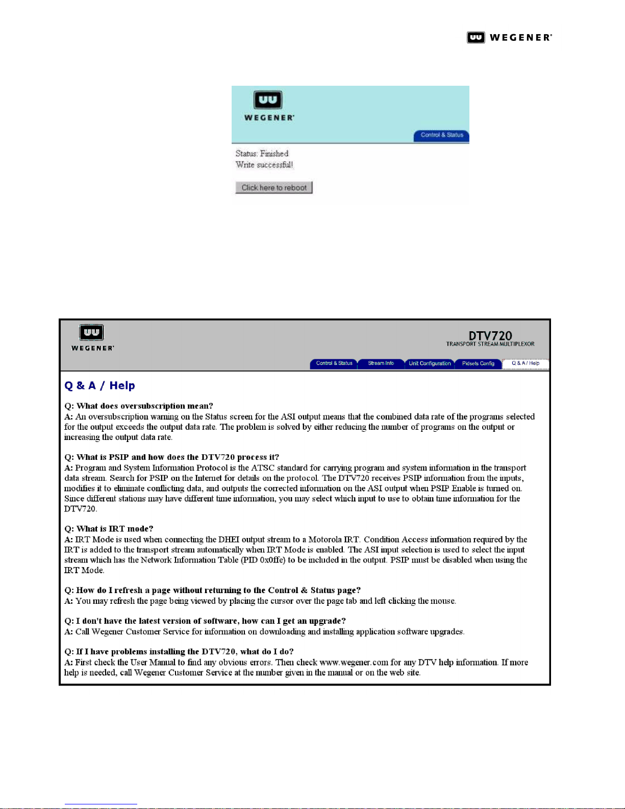
5. Once this is complete, the Status: message will be Finished and Write successful.
Clicking the Click here to reboot button now displayed below the Status: message will
restart the unit using the new firmware upgrade.
www.wegener.com 25 800043-01 Rev. C
Page 32
DTV 720 USER’S MANUAL
Figure 3.18: DTV 720 Module Config Page Firmware Upload Done
NOTE: This will reboot the unit, so it will interrupt the services that the unit is providing.
The upload process from start to end will take approximating 5 minutes to
complete.
Q&A/Help
Page
A list of questions and answers about operating your DTV 720 is available on the Q&A/Help
page. Click the Q&A/Help tab to display this page.
Figure 3.19: DTV 720 Web Browser Q&A/Help Page
800043-01 Rev. C 26 www.wegener.com
Page 33
3.3 DTV 720 Controls and Indicators
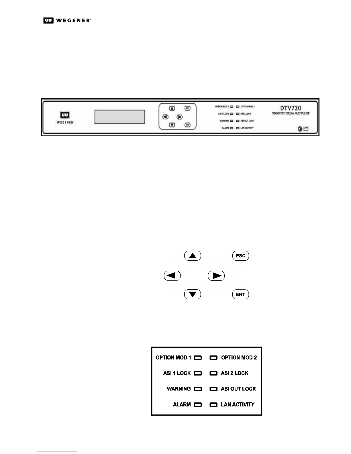
There are three major parts of your DTV 720’s front-panel controls and indicators: the liquid-crystal display (LCD), the six push buttons, and the eight LED indicators. Essentially
all control available through the terminal is also available via the front panel (shown below
in Figure3.20).
Figure 3.20: DTV 720 Unit Front Panel
DTV 720 USER’S MANUAL
LiquidCrystal
Display(LCD)
Front Panel
Push Buttons
Front Panel
LED
Indicators
The DTV 720 ’s 2-line by 20-character LCD indicates unit status and prompts for and
reflects user input. Here, on startup, you will see your DTV 720’s Home screen which
shows information on the input connections.
These six push buttons (shown below in Figure3.21) are your means of commanding the
DTV 720 from the front panel. The four arrow buttons allow navigation through the menu
screens and character selection when editing user-input fields. The Enter (ENT) button is
used to select menu options (downward navigation), to open user-input fields, or to commit user input to the DTV 720 . The Escape (ESC) button allows exit from user-input fields
without saving the entry or selection. ESC also provides upward navigation through the
menu structure to the Home screen. The arrow buttons also provide navigation through
user-input screens and switching between user-selectable options.
Figure 3.21: DTV 720 Front Panel Push Buttons
Figure3.22 below shows the eight light-emitting diodes (LEDs) that provide status informa-
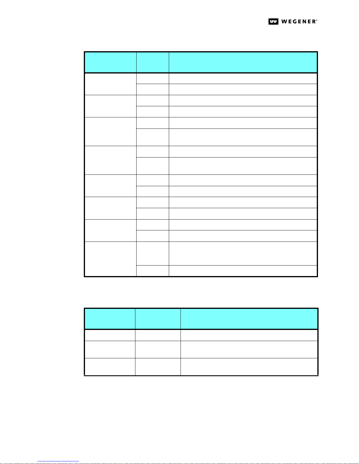
tion about your DTV 720 and its processes. Table 3.4: DTV 720 Front Panel LED Indicator
Descriptions provides the meaning of the color and state of each LED.
Figure 3.22: DTV 720 Front Panel LED Indicators
www.wegener.com 27 800043-01 Rev. C
Page 34
DTV 720 USER’S MANUAL
Table 3.4: DTV 720 Front Panel LED Indicator Descriptions
Indicator
Label and Color
OPTION MOD 1
(Green)
OPTION MOD 2
(Green)
ASI 1 LOCK
(Green)
ASI 2 LOCK
(Green)
WARNING
(Yellow)
ASI OUT LOCK
(Green)
ALARM
(Red)
Indicator
State
Constant Option module 1 installed and operating
Off Option module 1 not installed or not operating
Constant Option module 2 installed and operating
Off Option module 2 not installed or not operating
Constant ASI 1 input has Transport Stream synchronization present
Off ASI 1 input does not have Transport Stream
synchronization present
Constant ASI 2 input has Transport Stream synchronization present
Off ASI 2 input does not have Transport Stream
synchronization present
Constant Warning condition(s) exists
Off No Warning condition exists
Constant ASI Output is active
Off ASI Output is inactive
Constant Alarm condition(s) exists
Off No Alarm condition exists
Indicator Meaning
Rear Panel
LED
Indicators
LAN ACTIVITY
(Green)
Flash LAN activity present. Only lights when data is transferred to
the DTV 720. This is not a continuous monitor of LAN communications.
Off No transfer of LAN data to the unit
Three LED indicators on the rear panel give Ethernet and ASI Input status:
Table 3.5: DTV 720 Rear Panel LED Indicator Descriptions
Indicator Type
Indicator Label
ACT LED: Ethernet activity blinks OFF and ON for activity detected
LAN
ASI Input
and Color Indicator Meaning
LED Ethernet rate indicator, OFF for 10baseT and ON for
100baseT
Red/Green LED OFF for not selected, RED for no input signal, GREEN for
input signal detected
800043-01 Rev. C 28 www.wegener.com
Page 35
DTV 720 USER’S MANUAL
3.4 Front-Panel Operation
The DTV 720 may be set up and controlled from the front panel as follows:
NOTE: From any screen, pressing the ESC key twice will return you to the Home screen.
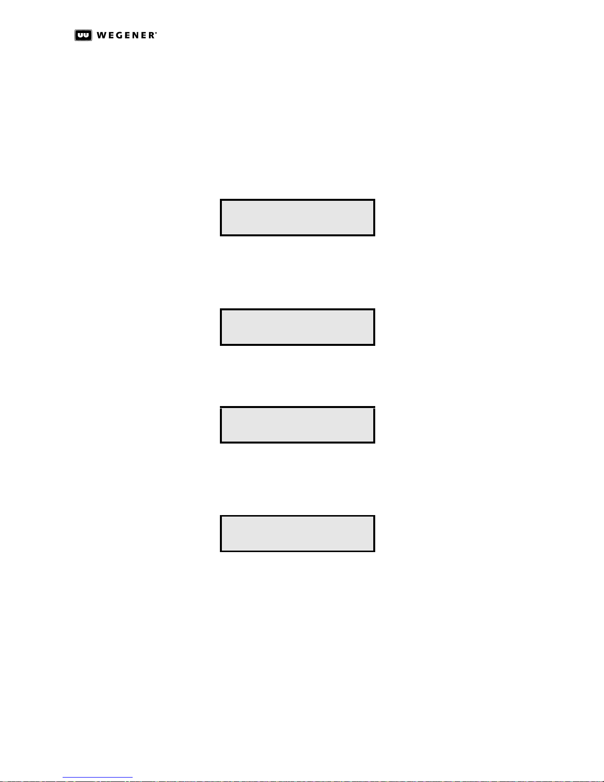
Home Screen The Home screen rotates through information displays for the standard two ASI inputs and
the optional RF input modules. Typical Home screens are illustrated below:
Active RF Input
RF1 Chan: XX 8VSB
SNRYY.Y ErrSec:ZZZZ
Where XX is the Broadcast Channel Number, YY.Y is the signal-to-noise ratio, and ZZZZ is
the number of errored seconds since the last Error counter reset.
Disabled RF Input
RF2 Disabled
Where the second RF tuner is disabled.
Active ASI Input
ASI 1 Enabled
Err Secs: 0000
Where ASI Input 1 is enabled, and no Errored Seconds have been recorded since the last
Error Counter reset.
Disabled ASI Input
ASI 2 Disabled
Where ASI Input 2 is disabled.
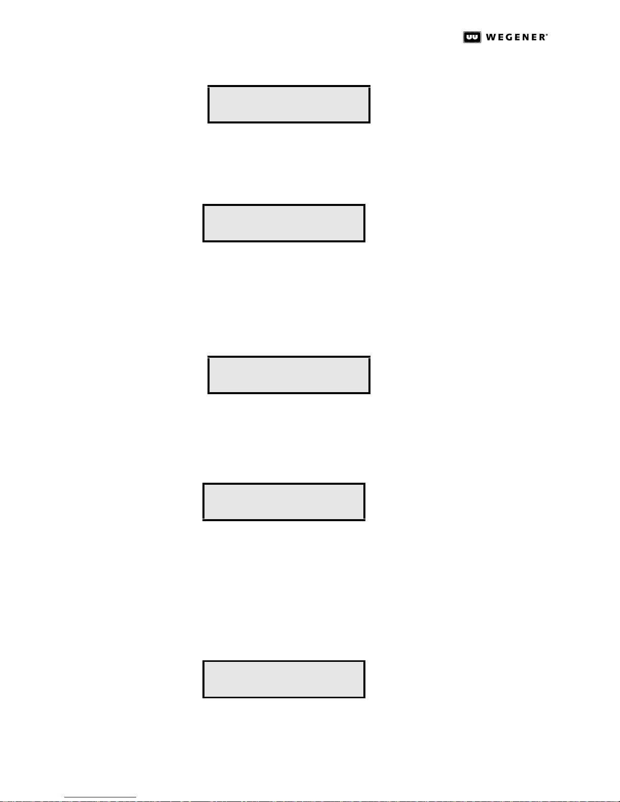
Press the ENT key to view the second-level Serial Number and Application Software Ver-
sion Number screen.
Press the ww key to go to Alarms/Warnings.
www.wegener.com 29 800043-01 Rev. C
Page 36
DTV 720 USER’S MANUAL
Second-Level Serial No.and Application Software Version Screen
Where XXXXXX is the unit's six-digit serial number and YYY is the version number of the
unit's currently installed application software.
Press the ESC key to return to the Home screen.
Alarms/
Warnings
Screen
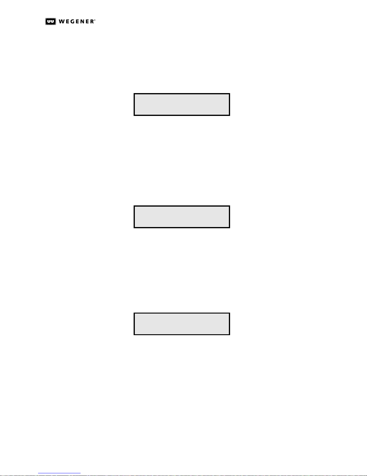
Press the ENT key to view any active alarms or warnings on the second-level Alarms/
Warnings Message screen.
Press the ww key to go to Clear Errored Seconds (if counter is non-zero) or Program Setup.
Press the ESC key to go to the Home screen.
S/N: XXXXXX
Version: YYY
View Alarms/Warnings
Clear Errored
Seconds
Screen
Input Setup
Screen
Alarms/Warnings Message Screen
No Alarms or Warning
Any active alarms or warnings are described here.
Press the ww key to view the next alarm or warning (if more than one is present).
Press the ESC key to return to the Alarms/Warnings screen.
Clear Errored Secs
Press<ENT>
Press ENT to clear the Errored Seconds counter.
Press the ww key to go to the Input Setup screen.
Press the vv key to go back to the Alarms/Warnings screen.
Press the ESC key to go to the Home screen.
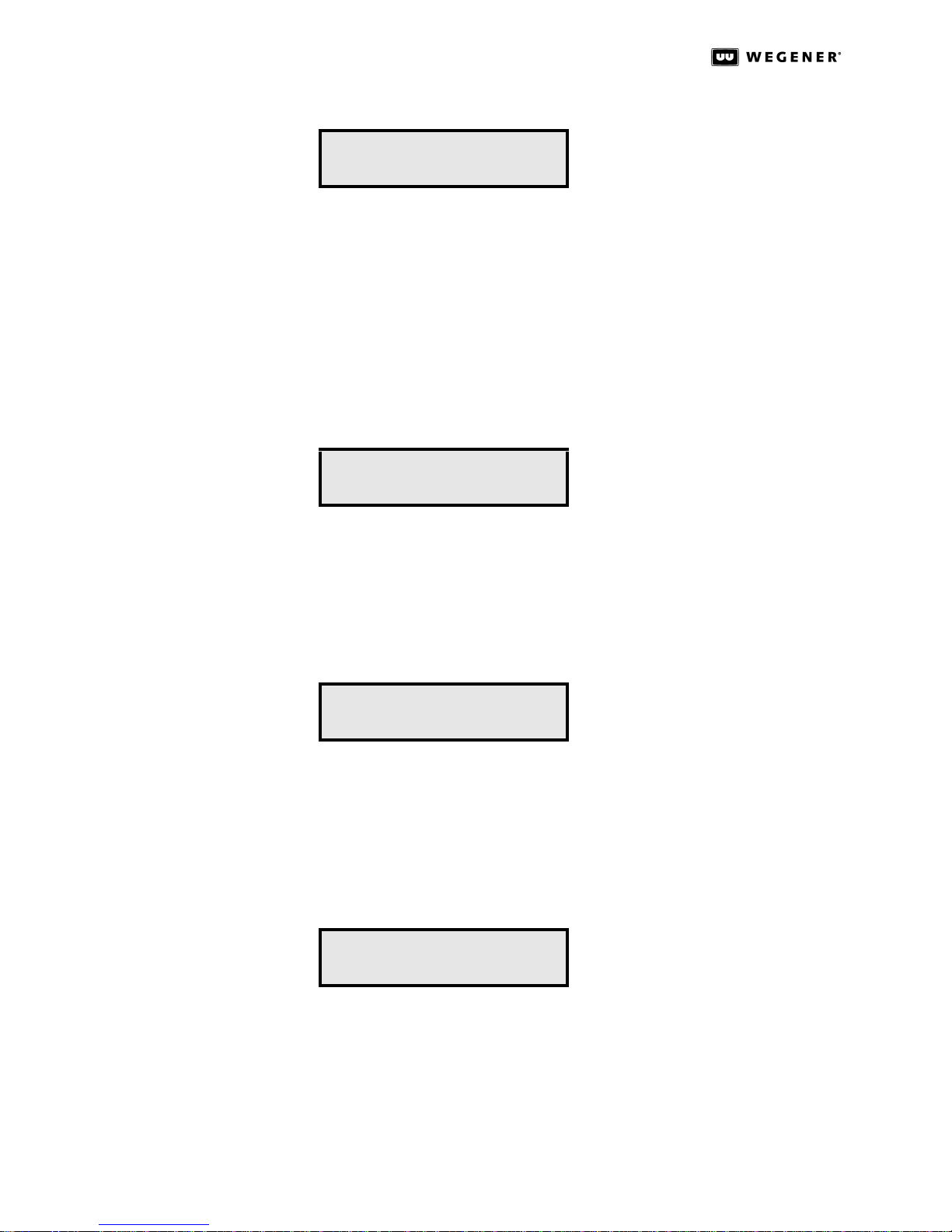
The Input Setup screen and its subscreens are used to enable and set parameters of ASI
and RF inputs.
Press the ENT key to bring up the second-level Input Setup screen.
Press the ww key to go to the Program Status screen.
800043-01 Rev. C 30 www.wegener.com
Input Setup...
Page 37
DTV 720 USER’S MANUAL
Press the vv key to go to Clear Errored Seconds (if the counter is non-zero).
Press the ESC key to go to the Home screen.
Second-Level Input Setup Screens
ASI Input 1 Screen
ASI Input 1
Press ENT to display the state of ASI Input 1 (ON or OFF). Press ENT again and use the r r
or ss keys to select either ON or OFF, enabling or disabling this input. Press ENT again to
confirm your selection.
Press the ww key to go to ASI Input 2.
Press the ESC key to return to the Input Setup screen.
Press the ESC key again to return to the Home screen.
ASI Input 2 Screen
ASI Input 2
This screen has the same functions as ASI Input 1 screen, but applies to ASI Input 2.
Press the ww key to go to RF Input 1.
Press the vv key to go back to ASI Input 1.
Press the ESC key to return to the Input Setup screen.
Press the ESC key again to return to the Home screen.
RF Input 1 Screen
RF Input 1
Press ENT to go to the third-level Tuner Enable Screen.
Press the ww key to go to RF Input 2 Setup.
Press the vv key to go back to ASI Input 2.
Press the ESC key to return to the Input Setup screen.
Press the ESC key again to return to the Home screen.
www.wegener.com 31 800043-01 Rev. C
Page 38
DTV 720 USER’S MANUAL
RF Input 2 Screen
Functions on this screen are identical to those for RF Input 1 but apply to RF Input 2.
Press ENT to go to the third-level Tuner Enable Screen.
Press the vv key to go back to RF Input 1.
Press the ESC key to return to the Input Setup screen.
Press the ESC key again to return to the Home screen.
Third-Level Input Setup Screens
Tuner Enable Screen
RF Input 2
Tuner Enable:
ON
Press ENT and the rr or ss keys to select ON or OFF, enabling or disabling this input.
Press ENT again to confirm.
Press the ww key to go to the Channel Number screen.
Press the ESC key to return to the RF Input screen.
Channel Number Screen
Channel Number:
10
Press ENT and the rr or ss keys to select the desired channel. Press ENT again to confirm.
Press the ww key to go to the RF Standard screen.
Press the vv key to go back to the Tuner Enable screen.
Press the ESC key to return to the RF Input screen.
RF Standard Screen
RF Standard:
Broadcast
Press ENT and the rr or ss keys to select either Broadcast or CATV. Press ENT again to
confirm.
Press the ww key to go to Channel Number.
Press the ESC key to return to the RF Input Screen.
800043-01 Rev. C 32 www.wegener.com
Page 39
Program
Status
Screen
DTV 720 USER’S MANUAL
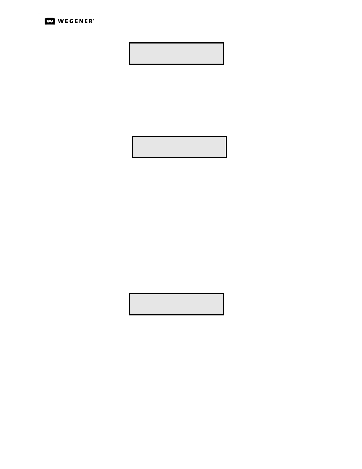
Program Status...
Press the ENT key to view the second-level Program Status screens.
Press the ww key to go to the Front Panel Timeout screen.
Press the vv key to go to the Input Setup screen.
Press the ESC key to go to the Home Screen.
Second-Level Program Status Screens
ProgIn XXXXX AAAAAAA
Out: YYY BBBBBBB
where XXXXX is the program number at input, AAAAAAA is the service descriptor for the
program, YYY is Yes or No, indicating whether or not the program is multiplexed into the
output stream, and BBBBBBB is the available audio on the input for the program (AC-3,
MPEG, or MPG/AC3).
Front Panel
Timeout
Screen
Press the ww key to view the status of the next program.
NOTE: All programs present may be viewed but only programs 1 through 16 may be
selected for output.
Press the ESC key to return to the Program Status screen.
After a period of inactivity, some information on the LCD is replaced with Help information
on how to use the front-panel controls. This timeout period (elapsed time between the last
front-panel activity and presentation of Help information) may be changed using the Front
Panel Timeout screen. For users familiar with front-panel operation, selecting No Timeout
will prevent the Help information from appearing. Other users may wish to set the timeout
period from 3 to 60 seconds.
Front Panel Timeout
10
Press the ENT key and then the rr or ss keys to select the Front Panel Timeout period
before the Help message is displayed. Values of 3, 5, 10, 30, or 60 seconds, or No Timeout
may be selected.
Press the ENT key to confirm the selection or ESC to cancel changes.
Press the ww key to go to the IP Setup screen.
Press the vv key to go back to the Program Status screen.
Press the ESC key to return to the Home screen.
www.wegener.com 33 800043-01 Rev. C
Page 40
DTV 720 USER’S MANUAL
IP Setup
Screen
Press the ENT key to go to the second-level IP Address Selection screen.
Press the ww key to go to the Reset Unit screen.
Press the vv key to go back to the Front Panel Timeout screen.
Press the ESC key to go to the Home screen.
Second-Level IP Setup Screens
IP Address Selection Screen
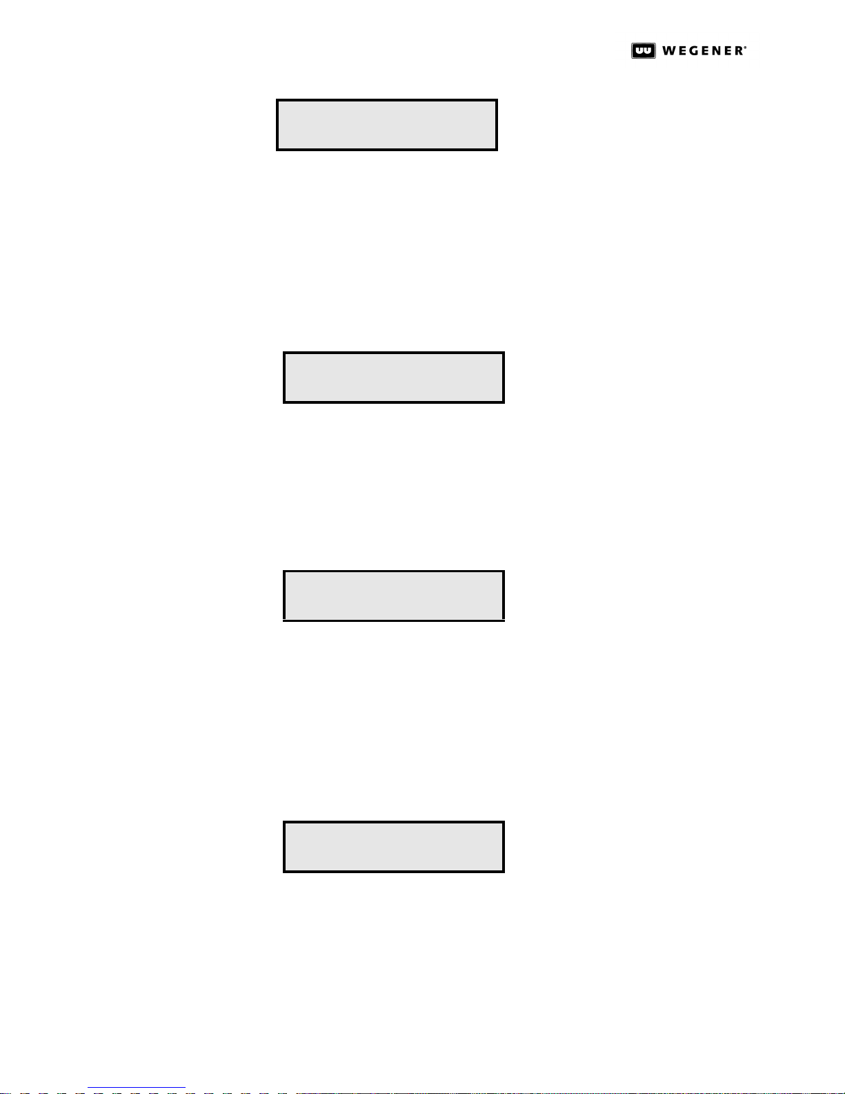
Press the ENT key and then press the arrow keys to change the IP address. Press the ENT
key to confirm the selection.
IP Setup...
IP Address:
000.000.000.000
Press the ww key to go to the Netmask Selection screen.
Press the ESC key to go to IP Setup.
Netmask Selection Screen
Netmask:
255.255.0.0
Press the ENT key and then press the arrow keys to change the Netmask. Press the ENT
key to confirm the selection.
Press the ww key to go to the Gateway Selection screen.
Press the vv key to go back to the IP Address Selection screen.
Press the ESC key to return to the IP Setup screen.
Gateway Selection Screen
Gateway:
0.0.0.0
Press the ENT key and then press the arrow keys to change the Gateway address. Press
the ENT key to confirm the selection.
Press the vv key to go back to the Netmask Selection screen.
Press the ESC key to return to the IP Setup screen.
800043-01 Rev. C 34 www.wegener.com
Page 41
Reset Unit
Screen
DTV 720 USER’S MANUAL
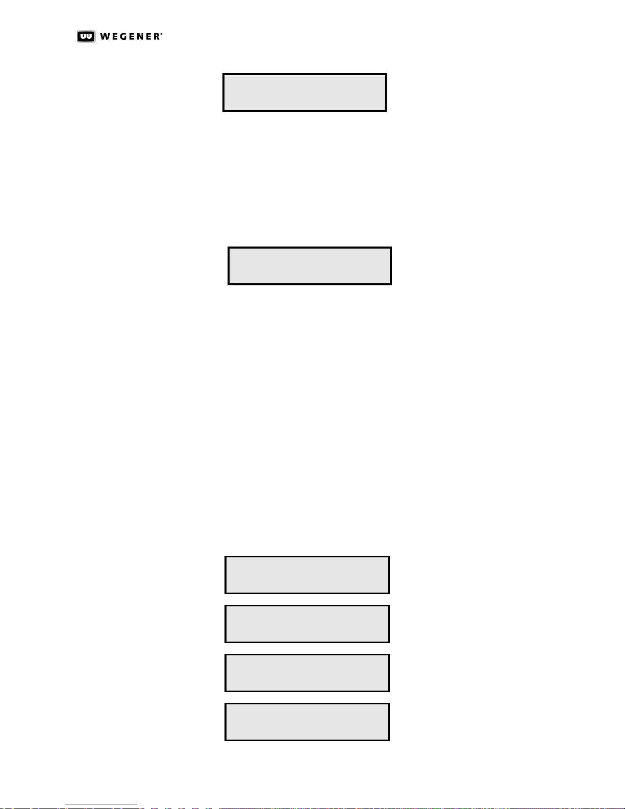
Reset Unit...
Press the ENT key to go to the second-level Reset Unit Entry screen.
Press the ww key to go to the Home screen.
Press the vv key to go back to the IP Setup screen.
Press the ESC key to return to the Home screen.
Second-Level Reset Unit Entry Screen
Reset Unit...
Press <ENT>
Press the ENT key to reset the unit and start the boot loader.
Press the ESC key to go back to the Reset Unit screen.
Unit
Shutdown
Simply remove power to the unit to shut down your DTV 720. No special procedure is
required.
3.5 Initialization
Software
Code
Structure
Initialization
Sequence
The DTV 720 Processor contains the following unit software: A boot loader and one version
of the operating application software. Before power-up, these components are stored in
non-volatile memory. The boot loader resides in a portion of the memory that may only be
written at the factory while the application is stored in a portion of memory that can be overwritten with down-loads of new software. The boot code has the responsibility of deciding if
the resident application software image should be allowed to execute.
At power up, the boot loader software executes first. It performs a test of RAM and then
relocates itself for further execution from there. During boot-up, the following screens
appear in sequence on the LCD:
FPCon v001
Hit key to stop boot
Booting in 2
All front-panel LEDs lights are
OFF during boot process.
www.wegener.com 35 800043-01 Rev. C
Booting System
Bootloader Ver 104
Done Booting
Bootloader Ver 104
Page 42

DTV 720 USER’S MANUAL
Following normal boot-up, the Home screen will appear as described in section 3.4 Front-
Panel Operation on page29 and the LEDs reflect the actual state of the unit.
Initialization
Failure
When in Initialization Failure mode, the unit is essentially dead. There is no ASI output, the
alarm relay is de-energized (alarm state), the Alarm LED is ON, and the unit does not
attempt acquisition of input streams. Call Wegener Customer Service.
3.6 Transport Stream Processing
Refer to ISO 13818-1 for supporting details on the structure of MPEG Transport Streams.
Input to
Output
Processing
PSIP
Structure and
Program
Selection
IRT Mode WARNING
The basic DTV 720 has two ASI inputs (and optionally two RF inputs or two more ASI
inputs). Program data from these inputs are multiplexed and output on two duplicate ASI
outputs. The unit processes the inputs, selects programs based on user input, and provides an output signal on the ASI outputs (and optional DHEI or GbE output). The processing includes program number changes as selected. Based on user selection, certain
programs may be selected and then passed to the ASI output with time stamping updated.
Within the transport stream, there are PIDs carrying tabular information on that stream.
The PAT describes all the programs available. The program number identifies each program in the transport stream. When a source of data is acquired, the stream is passed to
the internal transport demultiplexer. This circuit then extracts the PAT and PMT information and provides this information to the user via the Stream Info and Configuration pages
of the web interface. The user may then select programs to be included in the ASI output,
as described in section 3.2 Ethernet/Web Browser Control.
Do not select IRT mode unless using the DTV 720 with Motorola or General Instruments
equipment. Using IRT in other situations may have unexpected results.
NOTE: When using IRT mode, PSIP must be disabled.
With systems using the Motorola IRT product, certain additional elements must be
included in the output transport stream. In such systems, be sure to enable the DTV 720 ’s
IRT Mode by selecting IRT Mode ON from the web browser interface. (See Control and Sta-
tus Page on page15.) When the IRT Mode is ON, the DTV 720 performs the actions listed
below:
• A CAT (Conditional Access Table) PID (0x0001) is included and a CA system
descriptor is added in this packet pointing to a reserved location (PID 0x0FF9) for
the EMM (Encryption Management Message).
• For each program in the stream, a CA descriptor pointing to itself is added in the
PMT. This is a null ECM (Encryption Control Message).
• To the PAT, Program 0 (NIT) is added, pointing to PID 0x0FFE which carries the STT
(System Time Table) clock information.
• The NIT (Network Information Table) must also be present in the transport stream.
This PID (0x0FFE) is created at the uplink and is passed through.
800043-01 Rev. C 36 www.wegener.com
Page 43

3.7 Alarm and Warning System
The Alarm and Warning system is intended to provide the local user with indications when
a critical failure has occurred, or a failure is imminent. See Table 3.4: DTV 720 Front Panel
LED Indicator Descriptions on page 28 for actual indications.
DTV 720 USER’S MANUAL
Alarm
Conditions
Warning
Conditions
Generally, if the unit is unable (or presumed to be unable) to present output from a
selected transport stream, then that is an Alarm state. The following list defines all alarms
during normal operation. (Also see Initialization Failure on page36.)
1. Missing Input(s) – An expected stream is missing from one or more inputs.
2. PAT missing – The Transport Steam on the input does not have a PAT present
(should be located in PID 0x01.
3. PMT missing – The Transport Steam on the input does not have a PMT present
(should be located in PIDs as shown in the PAT).
Generally, the unit presents Warnings when an Alarm condition may be imminent due to
unit stress or poor signal conditions. The following specific conditions are defined as
Warnings:
1. Unit oversubscribed – The combined data rate of the selected input programs exceeds
the output data rate selected.
2. High Error Rate - Any input stream has more than one error per 10 seconds.
3.8 Software Downloads
The DTV 720 may be field-upgraded with new application software via the Ethernet port.
During the upgrade process, the DTV 720 will not be processing signals, so it is best to
take the unit offline while downloading new software. The entire process including the
upgrade and re-booting the unit requires about 1 1/2 minutes.
Before performing the Ethernet upgrade of the application software, you will need the following items:
• A Computer
• A LAN crossover cable
• The TFTPD32 FTP server program
• A utility program to unzip the TFTPD32 program
• The DTV upgrade software
To perform the Ethernet upgrade of the application software, do the following:
1. Download and save the DTV software upgrade from http://www.wegener.com/cust-
servdownload.html to a new directory called DTVSoftware on your local computer’s
hard drive.
2. Download and save the TFTPD32.zip file to the same folder as the software upgrade
on your local computer. This is a free shareware program available at http://
tftpd32.jounin.net/.
www.wegener.com 37 800043-01 Rev. C
Page 44
DTV 720 USER’S MANUAL
3. If your local computer is attached to a network, Wegener recommends that you discon-
nect the network cable from the computer and reset the computer before proceeding
to the following steps. The upgrade may not start up correctly if the computer isn’t
reset first.
4. Use your unzip utility to extract the TFTPD32.exe file from the TFTPD32.zip file.
5. Start and setup the TFTPD32.exe program on the PC:
a. Run TFTPD32.exe
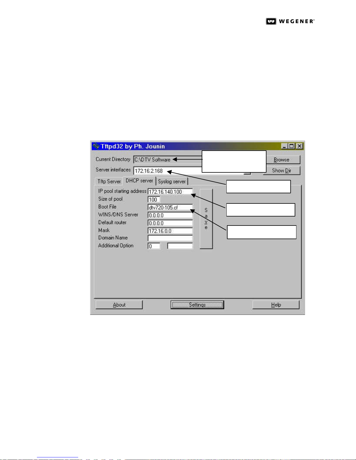
b. When the TFTPD32 window (Figure3.23 below) opens, set the Current Directory:
Figure 3.23: TFTPD32 Top-level Settings and DHCP Server Tab
field to the DTVSoftware directory where you placed the application code DTV 720 -
xxx.cf in Step 1. above.
Location of software
upgrade.
Your PC’s IP address
IP address of DTV unit
DTV Software upgrade
c. Look at the Server interfaces: field, which should contain your PC’s IP address.
(The TFTPD32 program should automatically set this from the information in your PC.)
d. Click the Settings button to bring up the TFTPD32: Settings screen shown in
Figure3.24.
e. Under Global Settings, click the checkboxes so that TFTP Server, Syslog Server,
and DHCP Server are checked to be ON, and that TFTP Client is not checked, or
OFF.
f. Under TFTP Security, click the radio button for Standard.
g. Under TFTP Configuration: set Timeout (seconds) to 3, Max Retransmit to 6, and
Tftp port to 69.
800043-01 Rev. C 38 www.wegener.com
Page 45
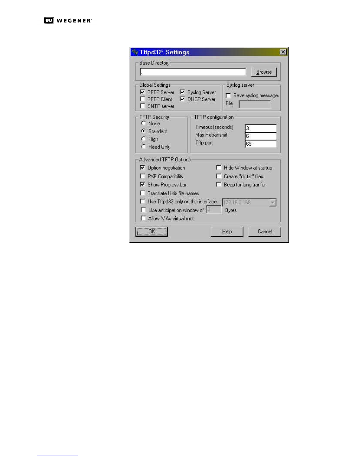
DTV 720 USER’S MANUAL
Figure 3.24: TFTPD32 Settings
h. Under Advanced TFTP Options: click the checkboxes to set Option negotiation and
Show Progress bar to be checked for ON, and all others unchecked or OFF.
i. Click the OK button, close the program, then re-open it.
10. Verify that the Current Directory on the TFTPD32 main window (Figure3.23) is correct.
11. Now click the Settings button and set the following items on the DHCP server tab:
NOTE: Press the Save button after every change or selection.
a. Set the IP pool starting address: to the IP address of the DTV unit being upgraded.
b. Set the Size of pool: field to 100.
c. Make sure that the Boot File: field displays the name of the downloaded DTV
upgrade software version: dtv720-xxx.cf where xxx must match the upgrade
revision.
d. The WINS/DNS Server: field should display 0.0.0.0.
e. The Default router: field should display 0.0.0.0.
f. Set the Mask: field to show the first two segments of the DTV unit’s IP address
followed by .0.0. (For example, if the DTV unit’s IP address is 172.16.90.150, then
the Mask: should be set to 172.16.0.0.)
g. Click the Save button.
www.wegener.com 39 800043-01 Rev. C
Page 46
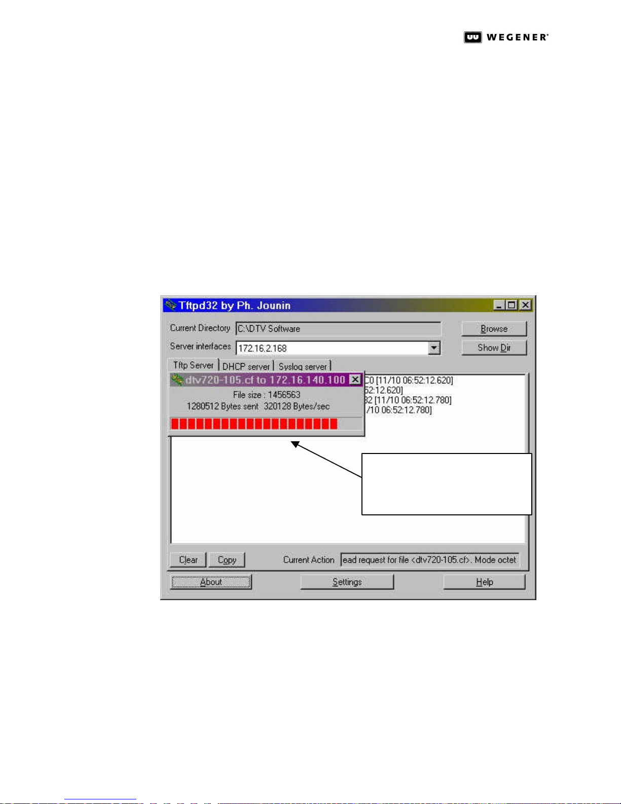
DTV 720 USER’S MANUAL
8. Connect the computer directly to your DTV 720 using a LAN crossover cable.
NOTE: Do not connect over a network.
9. Power up the DTV 720 and you should see on the front-panel LCD the message, Hit
any key to stop boot.
10. Press the ss arrow key immediately to interrupt the Boot Loader and enter the Upgrade
Mode.
NOTE: This screen is set to time-out after two seconds. You must act quickly.
11. Two options will appear on the LCD: Press ENT to upgrade and Press ESC to quit.
Press ENT. The upgrade transfer will start and lasts only about three seconds.
12. Watch the progress of the file transfer by selecting the Tftp server tab on the TFTPD32
main screen. A Progress bar showing the status of the ongoing transfer pops up as
shown in Figure3.25 below.
Figure 3.25: TFTPD32 Server Tab with File Transfer Progress Bar
Progress bar showing file transfer.
Note, it will only be on the screen
for about 3 seconds.
13. When the file transfer is complete, the progress bar disappears, and the file transfer
log can be read on the Tftp Server tab, as shown in Figure3.26 below.
14. The DTV 720 will automatically restart when the transfer is completed and written to
flash.
15. After the unit resets, verify that the correct code has been loaded by pressing ENT and
checking that the version number matches the xxx in the DTV 720-xxx.cf file.
16. After all units have been upgraded, Wegener recommends that you delete all the files
and folders used in this upgrade from your hard drive.
800043-01 Rev. C 40 www.wegener.com
Page 47
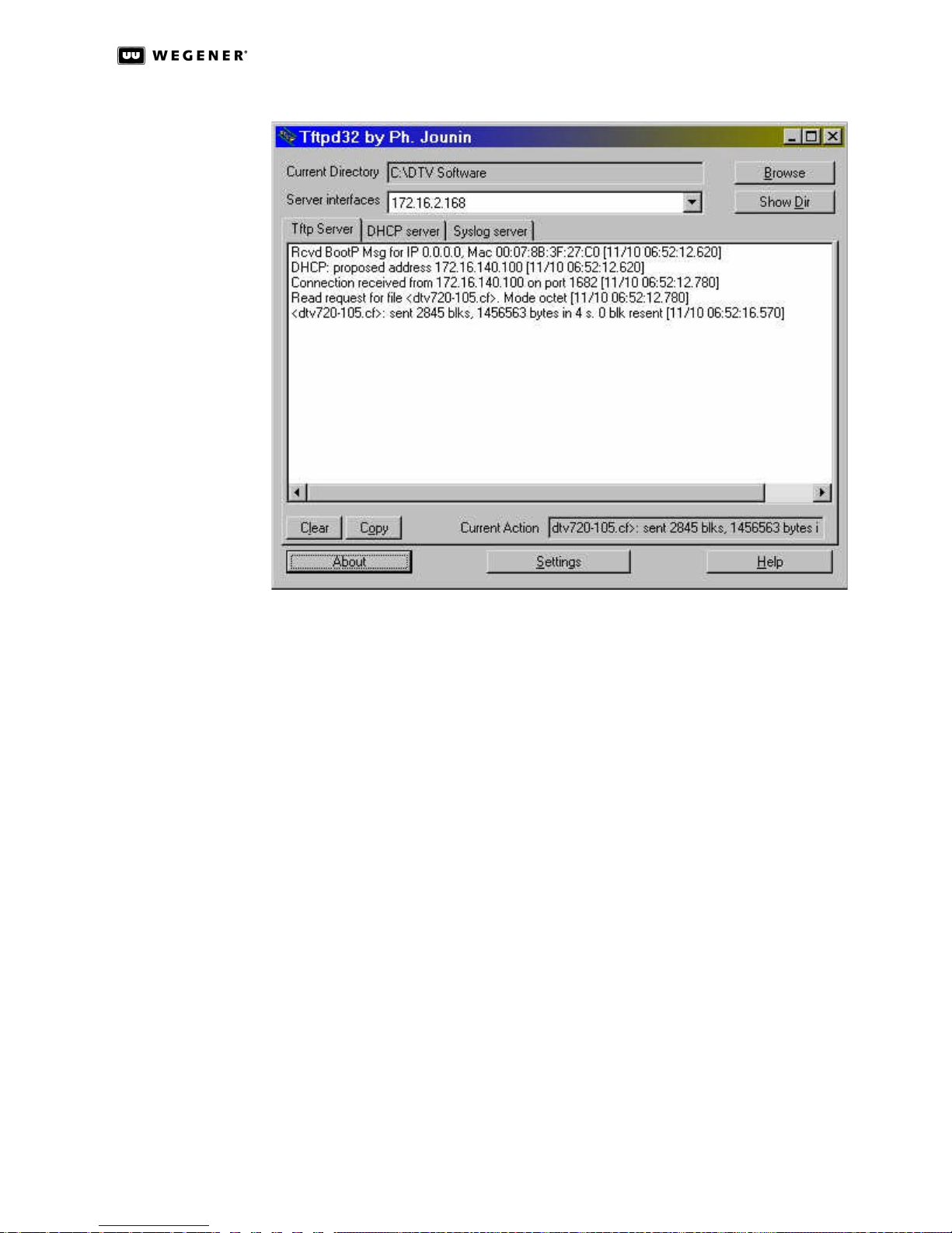
DTV 720 USER’S MANUAL
Figure 3.26: TFTP32 Server Tab Showing File Transfer Log
www.wegener.com 41 800043-01 Rev. C
Page 48

DTV 720 USER’S MANUAL
This page intentionally left blank.
800043-01 Rev. C 42 www.wegener.com
Page 49

DTV 720 USER’S MANUAL
Chapter 4 Maintenance and Troubleshooting
4.1 Maintenance
Maintenance of the DTV 720 is limited to keeping the chassis clean and ensuring that
cables remain firmly connected. Occasionally wipe the exterior with a soft, damp cloth to
remove any accumulated dust and dirt and check that cables are securely attached.
The DTV 720 incorporates security labels over some of the screws. There are no user-serviceable components within the DTV 720. Tampering with the security labels or opening
the unit will void your warranty. If you have any questions, contact Wegener’s Customer
Service Department at the address or numbers listed under Customer Service.
4.2 General Troubleshooting
This section is not an intended as an exhaustive list of all possible situations. Please contact us as directed in Chapter 5 Customer Service on page47, with any problems you
cannot resolve independently.
If you are experiencing any difficulties, first check the LCD and LED indicators on the DTV
720 to determine if any warnings or alarms are active. See Table 6: LED Indicator
Descriptions on page 27 for descriptions of LED states. If operating over the Ethernet
interface, check the Control and Status tab on your browser for Warning messages.
In the following sections, LEDs are illustrated as black (off) or white (on) to represent
actual LED appearance.
No Functions
at All
If the unit is not functioning at all and neither the LCD nor any LEDs are active, there may
be a loss of ac power. Do the following:
a. Check that ac power cord is firmly connected at both ends.
b. Check that your ac power source is supplying ac power.
www.wegener.com 43 800043-01 Rev. C
Page 50
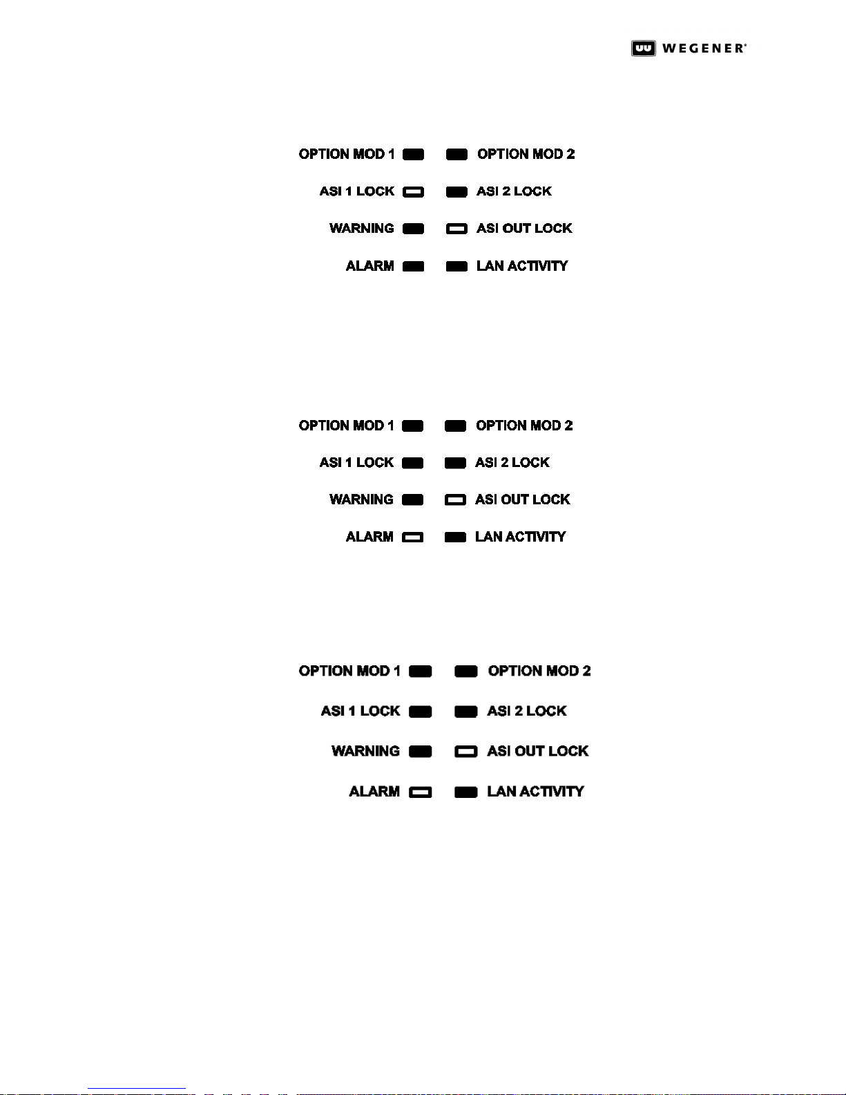
DTV 720 USER’S MANUAL
Normal
Operation
4.3 Alarms
ALARM:
Input Missing
The LEDs are shown here reflecting the DTV 720 in normal operation with no Alarms or
Warnings (the WARNING and ALARM LEDs are unlit, ASI OUT LOCK is lit, and one or more
of the OPTION MOD or ASI LOCK LEDs are lit):
Video is lost when an incoming signal is lost. When an OPTION MOD (if an optional RF port
is installed) or ASI LOCK LED is inactive or unlit for a port or ports from which an input
stream is expected, the ALARM LED will light (shown below). Check input sources and
connections.
ALARM: PAT
or PMT
Missing
Video is lost when the incoming signal is missing either the PAT or PMT. When the ALARM
LED is lit and both the ASI 1 LOCK and the ASI OUT LOCK LEDs are lit then the transport
stream does not have sufficient PSI information included. Check with the service provider
to ensure that the source is correct.
4.4 Warnings
WARNING:
Unit Oversubscribed
An oversubscription alarm means that the total rate of the selected inputs is greater than
the selected output rate. A corrupt signal is output from the DTV 720. Oversubscription
results in errors in the video output. On the front panel, this is indicated by a lit ALARM
LED and an unlit ASI OUT LOCK LED (shown below). Solve the problem by reducing the
number of input programs to fit the combined input data rate within the selected output
data rate.
800043-01 Rev. C 44 www.wegener.com
Page 51
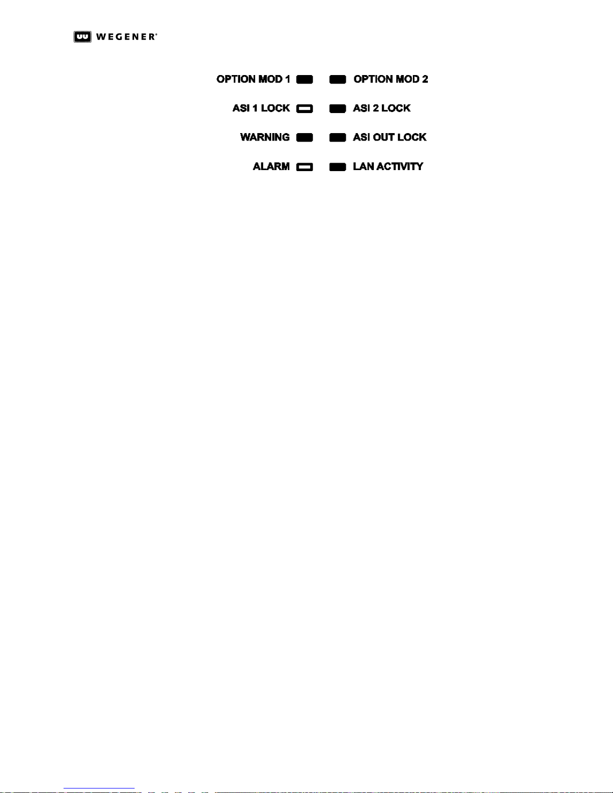
4.5 Trouble with Browser Interface
If the unit appears to be functioning normally with no alarm or warning conditions, but you
cannot use the web browser interface, first check the LED on the rear panel next to the
Ethernet connector. It will illuminate and blink as LAN data are detected. If this LED is off
check the cabling to the LAN. If the LED remains off after verifying the LAN connection,
contact Customer Service. If the Ethernet LED is illuminated, check that you are using the
correct IP address. (See “Ethernet/Web Browser Control” on page17.)
DTV 720 USER’S MANUAL
If the address is correct, but the interface still does not function, check your computer’s IP
settings and consult your network administrator for additional help.
www.wegener.com 45 800043-01 Rev. C
Page 52

DTV 720 USER’S MANUAL
This page intentionally blank
800043-01 Rev. C 46 www.wegener.com
Page 53

Chapter 5 Customer Service
5.1 Warranty
The following warranty applies to all Wegener Communications products including the
DTV 720 Transport Stream Multiplexer:
All Wegener Communications products are warranted against defective materials and
workmanship for a period of one year after shipment to customer. Wegener
Communications' obligation under this warranty is limited to repairing or, at Wegener
Communications' option, replacing parts, subassemblies, or entire assemblies.
Wegener Communications shall not be liable for any special, indirect, or
consequential damages. This warranty does not cover parts or equipment which have
been subject to misuse, negligence, or accident by the customer during use. All
shipping costs for warranty repairs will be prepaid by the customer. There are no other
warranties, express or implied, except as stated herein.
5.2 Technical Support
In the event that the unit should fail to perform as described, or if you need help
resolving problems with your DTV 720 , contact Wegener Communications Customer
Service at (770) 814-4057, FAX (678) 624-0294, or E-mail [email protected].
DTV 720 USER’S MANUAL
To return a product for service:
a. Obtain a Return Material Authorization (RMA) number by completing and faxing a
copy of the RMA Request Form to (678)624-0294. You may E-mail the same
information instead to: [email protected]
b. To help us identify and control returned units, plainly write the RMA number on the
outside of the product-shipping container. This will help us return your unit to you
as quickly as possible.
c. Return the product, freight prepaid, to the address below:
Service Department RMA# ________
Wegener Communications, Inc.
359 Curie Drive
Alpharetta, GA 30005
NOTE:All returned material must be shipped freight prepaid. C.O.D. Shipments
will not be accepted.
Please contact Customer Service at the number above if you have any questions about
obtaining service for your DTV 720.
www.wegener.com 47 800043-01 Rev. C
Page 54

DTV 720 USER’S MANUAL
This page intentionally left blank.
800043-01 Rev. C 48 www.wegener.com
Page 55

Index
DTV 720 USER’S MANUAL
A
AC Power . . . . . . . . . . . . . . . . . . . .7
address
customer service . . . . . . . . . . . .47
manual comments or
questions . . . . . . . . . . . . . . . . .5
air flow . . . . . . . . . . . . . . . . . . . . . .12
alarm relays . . . . . . . . . . . . . . . . . . .8
alarm system . . . . . . . . . . . . . . . . .37
ASI Input LED . . . . . . . . . . . . . . . .28
C
chassis
description . . . . . . . . . . . . . . . . . . 6
dimensions . . . . . . . . . . . . . . . . . .7
circuit overloading . . . . . . . . . . . . .12
cleaning . . . . . . . . . . . . . . . . . . . . . 43
connections
ac power . . . . . . . . . . . . . . . . . . .15
grounding . . . . . . . . . . . . . . . . . . 14
LAN . . . . . . . . . . . . . . . . . . .15, 18
output . . . . . . . . . . . . . . . . . . . . . 15
relays . . . . . . . . . . . . . . . . . . . . .15
connector details . . . . . . . . . . . . . .15
Control and Status page . . . . . 19-21
controls and indicators . . . . . . . . . .26
D
definitions . . . . . . . . . . . . . . . . . . . .9
dimensions . . . . . . . . . . . . . . . . . . .7
E
earthing . . . . . . . . . . . . . . . . . . . . .12
email
customer service . . . . . . . . . . . .47
regarding manual . . . . . . . . . . . . .5
Enter (ENT) button . . . . . . . . . . . .26
environment, operating . . . . . . . . . .7
equipment rack . . . . . . . . . . . . . . .13
Escape (ESC) button . . . . . . . . . . . 26
Ethernet
connection and use . . . . . . .16, 18
port . . . . . . . . . . . . . . . . . . . . . . . . 8
expansion module slot . . . . . . . . . . .8
front panel
appearance . . . . . . . . . . . . . . . .6
figure and description . . . . . . .26
operation from . . . . . . . . . . . . .29
G
gateway . . . . . . . . . . . . . . . . . . .18
glossary of terms . . . . . . . . . . . . .9
grounding . . . . . . . . . . . . . 12, 13, 14
H
help . . . . . . . . . . . . . . . . . . . . . . . . 25
home screen . . . . . . . . . . . . . . . . . 29
I
initialization . . . . . . . . . . . . . . . . . . 35
initialization sequence . . . . . . . . . . 36
IP address . . . . . . . . . . . . . . . . . . . 18
L
labels, security . . . . . . . . . . . . . . . 43
LAN connection . . . . . . . . . . . 15, 18
LCD
description . . . . . . . . . . . . . . . . . 26
screens . . . . . . . . . . . . . . . . .29-35
LED indicators . . . . . . . . . . . . . . . 27
LEDs
alarm . . . . . . . . . . . . . . . . . . . . . 28
ASI LOCK (1 & 2) . . . . . . . . . . . 27
ASI OUT LOCK . . . . . . . . . . . . . 28
LAN ACTIVITY . . . . . . . . . . . . . 28
OPTION MOD (1 & 2) . . . . . . . . 27
rear-panel . . . . . . . . . . . . . . . . . 28
WARNING . . . . . . . . . . . . . . . . . 28
local control . . . . . . . . . . . . . . . . . 17
M
maintenance . . . . . . . . . . . . . . . .43
mechanical loading . . . . . . . . . . . 12
mechanical specifications . . . . . . .7
menus . . . . . . . . . . . . . . . . . . 29-35
mounting
equipment rack . . . . . . . . . . . .13
location and . . . . . . . . . . . . . . .11
output connections . . . . . . . . . . . . .15
P
phone number
customer service 47
Pidsets Config page . . . . . . . . . 23-24
pinouts . . . . . . . . . . . . . . . . . . . . . .15
push buttons . . . . . . . . . . . . . . . . . 26
Q
Q&A/Help page . . . . . . . . . . . . . . . 25
R
rack mounting . . . . . . . . . . . . . . . .13
rear panel
figure and connections . . . . . . . . 14
LEDs . . . . . . . . . . . . . . . . . . . . . . 28
relays
connection of . . . . . . . . . . . . . . . 15
Return Material Authorization . . . . 47
S
safety . . . . . . . . . . . . . . . . . . . . . . . .8
screens . . . . . . . . . . . . . . . . . . 29-35
serial port . . . . . . . . . . . . . . . . . .7, 16
shutdown . . . . . . . . . . . . . . . . . . . .35
size of DTV720 . . . . . . . . . . . . . . . .7
software structure . . . . . . . . . . . . .35
specifications . . . . . . . . . . . . . . . . . .7
Stream Information page . . . . . . . . 22
stream processing . . . . . . . . . . . . .36
suggestions or comments . . . . . . . .5
system setup . . . . . . . . . . . . . . . . .14
T
temperature, ambient operating . . .12
terminal I/O . . . . . . . . . . . . . . . . . .16
TMRA . . . . . . . . . . . . . . . . . . . . . . .12
troubleshooting . . . . . . . . . . . . . . . 43
U
Unit Configuration page . . . . . . . . . 23
unpacking . . . . . . . . . . . . . . . . . . .11
F
fax number
customer service . . . . . . . . . . . .47
manuals . . . . . . . . . . . . . . . . . . . .5
front brackets . . . . . . . . . . . . . . . . .13
www.wegener.com 49 800043-01 Rev. C
N
netmask . . . . . . . . . . . . . . . . . . . 18
O
opening the chassis . . . . . . . . . . . . 8
W
warranty . . . . . . . . . . . . . . . . . . . . .47
web browser control . . . . . . . . .17, 18
Page 56

DTV 720 USER’S MANUAL
800043-01 Rev. C 50 www.wegener.com
 Loading...