

Page 1
Motors | Automation | Energy | Transmission & Distribution | Coatings
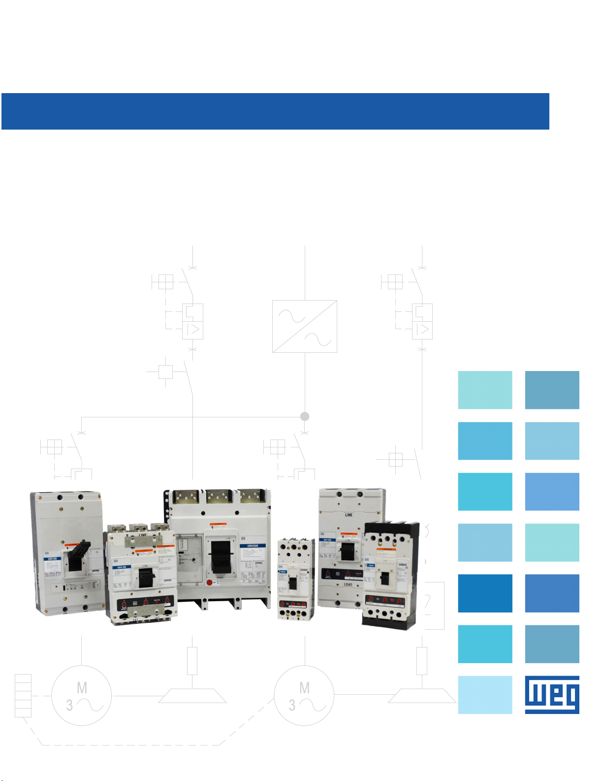
UBW Technical Manual
US.UBW.Tech.Manual.2018
Page 2

Table of Contents
UBW Technical Manual
General Description .............................................................................................................................3
Part Number Description ......................................................................................................................4
Interrupt Capacity Ratings ....................................................................................................................5
UBW 225 Trip Curves (15 - 225A).........................................................................................................6
UBW 250 Trip Curves .........................................................................................................................33
UBW 400 Trip Curves .........................................................................................................................35
UBW 600 Trip Curves .........................................................................................................................37
UBW 800 Trip Curves .........................................................................................................................39
UBW 1200 Trip Curves .......................................................................................................................40
UBW 2500 Trip Curves .......................................................................................................................42
Let Thru Curves .................................................................................................................................46
UBW Dimensions
...............................................................................................................................49
2 Data subject to change without notice.
Page 3

General Description
General Circuit
Breaker Information
WEG’s molded-case circuit breakers are
designed to provide circuit protection for low
voltage distribution systems. They are
described by NEMA as, “. . . a device
for closing and interrupting a circuit between
separable contacts under both normal and
abnormal conditions,” and further- more as,
“. . . a breaker assembled as an integral
unit in a supporting and enclosing housing of
insulating material.” The NEC® describes
them as, “A device designed to open and
close a circuit by non-automatic means, and
to open the circuit automatically on a
predetermined overload of current, without
injury to itself when properly applied within
its rating.”
So designed, WEG circuit breakers protect
conductors against overloads and conductors
and connected apparatus, such as motors
and motor starters, against short circuits.
Circuit Breaker Components and
Functions
Being essentially high interrupting capacity
switches with repetitive elements, WEG’s
circuit breakers are comprised of three main
functional components. These are:
1. Trip elements (thermal-magnetic or
electronic)
2. Operating mechanism
3. Arc extinguishers
1. Trip Elements
The function of the trip element is to trip the
operating mechanism in the event of a
prolonged overload or short-circuit current. To
accomplish this, a thermal- magnetic trip
action is provided.
Thermal-Magnetic Breakers
WEG thermal-magnetic breakers are general
purpose devices suitable for the majority of
breaker applications and are considered the
industry standard. Available from 15–800 A,
thermal-magnetic breakers provide accurate
reliable overload and short- circuit protection
for conductors and connected apparatus.
Thermal trip action is achieved through the
use of a bimetal heated by the load current.
On a sustained over- load, the bimetal will
deflect, causing the operating mechanism to
trip.
Because bimetals are responsive to the heat
emitted by the current flow, they allow a longtime delay on light overloads, yet they have a
fast response on heavier overloads.
Magnetic trip action is achieved through the
use of an electromagnet in series with the
load current. This provides an instantaneous
tripping action when the current reaches a
predetermined value. Front-adjustable
magnetic trip elements are supplied as
standard on 250 A frame circuit breakers and
above 225 are fixed thermal and magnetic
Electronic RMS Trip Breakers
WEG electronic trip breakers are generally
applied for applications where high levels of
system coordination are called for. Available
from 500–2500 A, today’s electronic trip
breakers can provide superior protection and
coordination as well as additional protection
features. Both the overload trip action and the
short-circuit trip action of breakers with
Digitrip electronic trip units are achieved by
the use of current transformers and solidstate circuitry that monitors the current and
initiates tripping through a flux shunt trip
when an overload or a short circuit is present.
All multiple-pole circuit breakers have trip
elements in each pole and a common trip bar.
An abnormal circuit condition in any one pole
will cause all poles to open simultaneously.
Electronic RMS trip breakers can include trip
features such as:
• Adjustable long-time pickup
• Adjustable short-time pickup
• Adjustable long delay time
• Adjustable short delay time
• Adjustable instantaneous pickup
Trip unit adjustments are made by setting
switches on the front of the trip unit or by
programming the trip unit electronically.
All electronic RMS trip breakers are equipped
with a manual push-to-trip mechanism.
Molded-Case Circuit Breakers
2. Operating Mechanism
The function of the operating mechanism is to
provide a means of opening and closing the
breaker contacts. All mechanisms are of the
quick-make, quick-break type and are “trip
free.” “Trip free” mechanisms are designed
so that the contacts cannot be held closed
against an abnormal circuit condition and are
sometimes referred to as an “overcenter
toggle mechanism.” In addition to indicating
whether the breaker is “on” or “off,” the
operating mechanism handle indicates when
the breaker is “tripped” by moving to a
position midway between the extremes. This
distinct trip point is particularly advantageous
where breakers are grouped, as in
panelboard applications, because it clearly
indicates the faulty circuit. The operating
mechanism contains a positive on feature. In
the normal switching operation, the handle of
the circuit breaker will not be capable of
being left readily at or near the off position
when the main contacts are closed.
3. Arc Extinguishers
The function of the DE-ION® arc extinguisher
is to confine, divide
extinguish the arc drawn between opening
breaker contacts. It consists of specially
shaped steel grids isolated from each other
and supported by an insulating housing.
When the contacts are opened, the arc drawn
induces a magnetic field in the grids, which in
turn draws the arc from the contacts and into
the grids. The arc is thus split into a series of
smaller arcs and the heat generated is quickly
dissipated through the metal. These two
actions result in a rapid removal of ions from
the arc, which hastens dielectric build- up
between the contacts and results in
rapid extinction of the arc.
Data subject to change without notice. UBW Technical Manual | 3
Page 4
Molded-Case Circuit Breakers
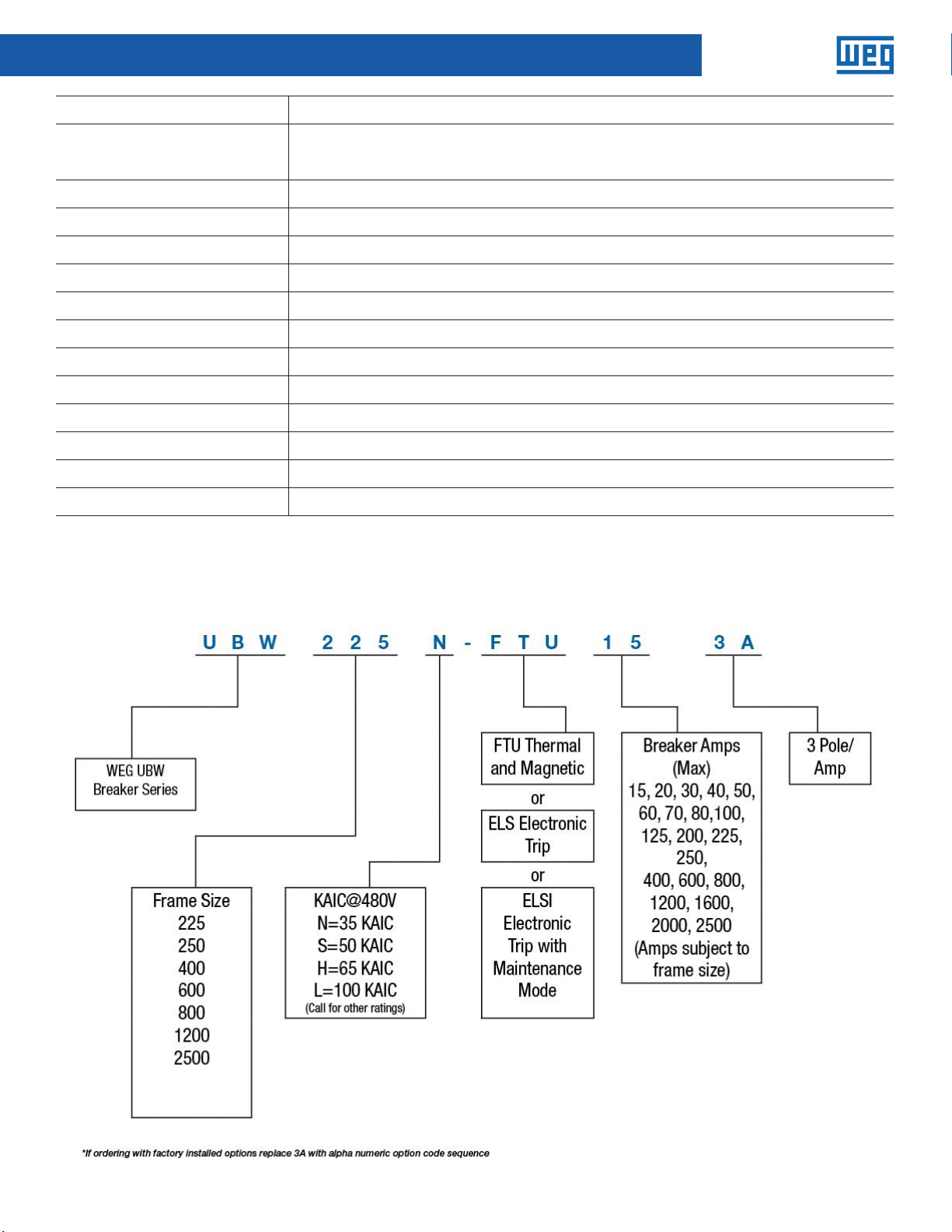
Description UBW Breakers Frames 225 to 2500
Select trip
Operator type Types of operators: mechanically operated over-center toggle or motor operator
Closing speed Greater than 5-cycle closing for electrically operated devices
Mounting Typically fixed-mounted but large frame sizes may be available in drawout construction
Interrupting rating Interrupting duty at 480 Vac: 22–100 kA
Current limiting Current limiting available with and without fuses up to 200 kA
Relative cost Low
Available frame sizes Large number of frame sizes available. Typical 15–2500 A
Maintenance Very limited maintenance possible on larger frame sizes
Enclosure types Used in enclosures, panelboards, switchboards, MCCs and control panels
Series ratings Available in series ratings
Enclosed rating 80% continuous-current rated
Standards NEMA AB1/AB3 UL 489
Selective trip over a smaller range of fault currents within the interrupting rating (low short-time
ratings). Typically 10–13 times the frame size
UBW Part Number Sequence
4 Data subject to change without notice.
Page 5
Molded-Case Circuit Breakers
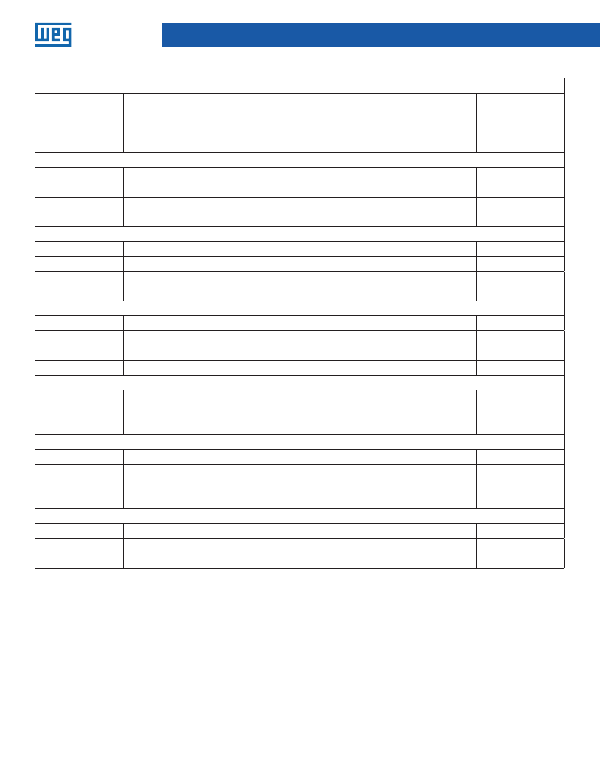
Interupting Capicity Ratings
225 Frame
Type Poles 240ac 480ac 600ac 250dc
N 3 65K 35K N/A 10K
H 3 100K 65K N/A 22K
L 3 200K 100K N/A 22K
250 Frame
Type Poles 240ac 480ac 600ac 250dc
N 3 65K 35K 18K 10K
H 3 100K 65K 25K 22K
L 3 200K 100K N/A 22K
400 Frame
Type Poles 240ac 480ac 600ac 250dc
N 3 65K 35K 18K 10K
H 3 100K 65K 35K 22K
L 3 200K 100K 65K 22K
600 Frame
Type Poles 240ac 480ac 600ac 250dc
N 3 65K 35K 25K 22K
H 3 100K 65K 35K 25K
L 3 200K 100K 50K 30K
800 Frame
Type Poles 240ac 480ac 600ac 250dc
S 3 65K 50K 25K 22K
H 3 100K 65K 35K 25
1200 Frame
Type Poles 240ac 480ac 600ac DC Rated
S 3 85K 50K 25K NO
H 3 100K 65K 35K NO
L 3 N/A 100K 65K NO
2500 Frame
Type Poles 240ac 480ac 600ac DC Rated
H 3 125K 65K 50K NO
L 3 200 100K 65K NO
Data subject to change without notice. UBW Technical Manual | 5
Page 6
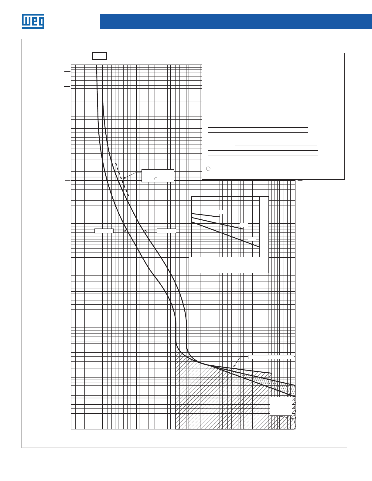
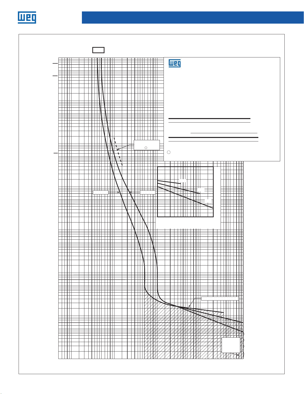
Molded-Case Circuit Breakers
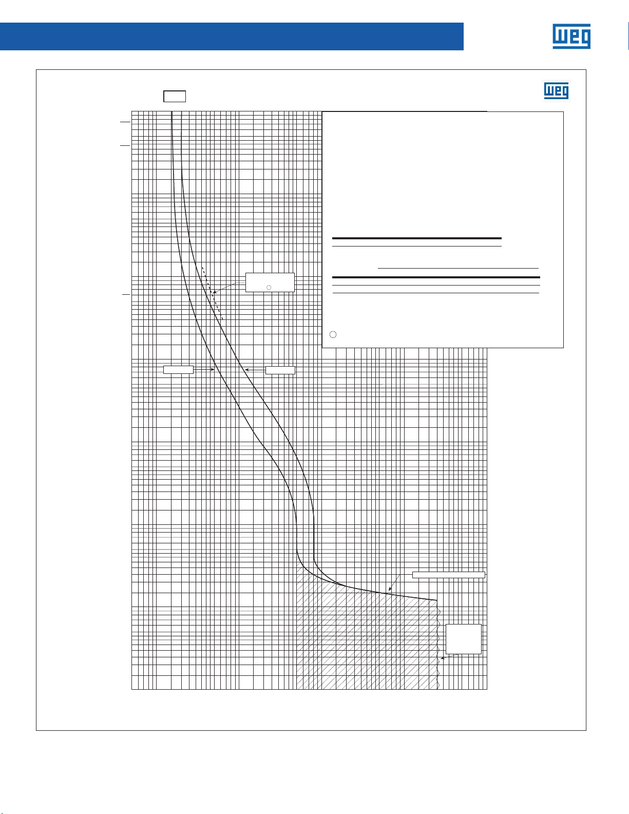
UBW Time Current Curves
225N/H
10,000
2 HOURS
5,000
1 HOUR
3,000
2,000
1,000
500
300
200
100
50
1 MINUTE
30
20
10
5
15A
Minimum
8060 9070504030201 0 9 8 75 6
100
CURRENT IN AMPERES
300
200
Maximum singlepole trip times
1
at 25°C
Maximum
400
Circuit breaker time/current curves
F-frame circuit breakers
Catalog types ED, EHD, FDB, FD and HFD circuit breakers, two-, three-
and four-poles.
Circuit breaker time/current curves
For application and coordination purposes only.
Series 225 frame circuit breakers
Based on 40˚C ambient, cold start. Connected with four (4) feet of
rated wire (60˚C
Tested in open air with current in all
For application and coordination purposes only. Based on 40°C ambient, cold start.
Maximum Vac: 600 at 50/60 Hz
Connected with four (4) feet of rated wire (60°C up to 125A, 75°C above 125A) per
Maximum Vdc: 250
terminal. Tested in open air.
Breaker rating
Continuous amperes Instantaneous trip amperes
Maximum Vac: 600 at 50/60 Hz
15A See curve
Maximum Vdc: 250
Interrupting Rating (UL/CSA Listed)
Breaker
Symmetrical Rms amperes (KA) Amps (KA)
type
Breaker rating
Continuous amperes Instantaneous trip, amperes
15A See curve
Interrupting Rating (UL/CSA Listed)
Breaker Type
N
H
@ 240 Vac @ 480 Vac @ 600 Vac 250 Vac 125V
18
EHD
18
FDB
65
FD
100
HFD
ED 65
1
Single-pole test data at 25˚C based on NEMA procedures
(AB
4-2003
) for verifying performance of molded case
circuit breakers.
Symmetrical RMS amperes (kA)
@240Vac @480Vac @600Vac 250Vac
65 35 18 10
100 65 25 22
pole.
—
14
14
35
65
—
10
14
18
25
—
—
10
—
10
—
22
10
—
5,000
3,000
2,000
1,000
500
300
200
100
50
2 HOURS
1 HOUR
10000
8000
6000
9000
7000
5000
4000
3000
2000
1000
800
600
900
700
500
Notes:
1 Single-pole test data at 25°C based on NEMA procedures (AB 4-2003) for verifying
performance of molded case circuit breakers.
20
10
5
3
2
1
.5
TIME IN SECONDS
.3
.2
.1
.05
.03
.02
.01
.005
.003
.002
.001
56
3
TIME IN SECONDS
2
1
.5
.3
.2
.1
.05
Maximum interrupting time
Interrupting
rating
determines
end of curve
(see above)
60
40
20
987
10
30
80
7050
90
200
100
500
700
800
600
900
400
300
CURRENT IN AMPERES
1000
2000
3000
4000
5000
6000
7000
8000
9000
10000
.03
.02
.01
.005
.003
.002
.001
6 Data subject to change without notice.
Page 7
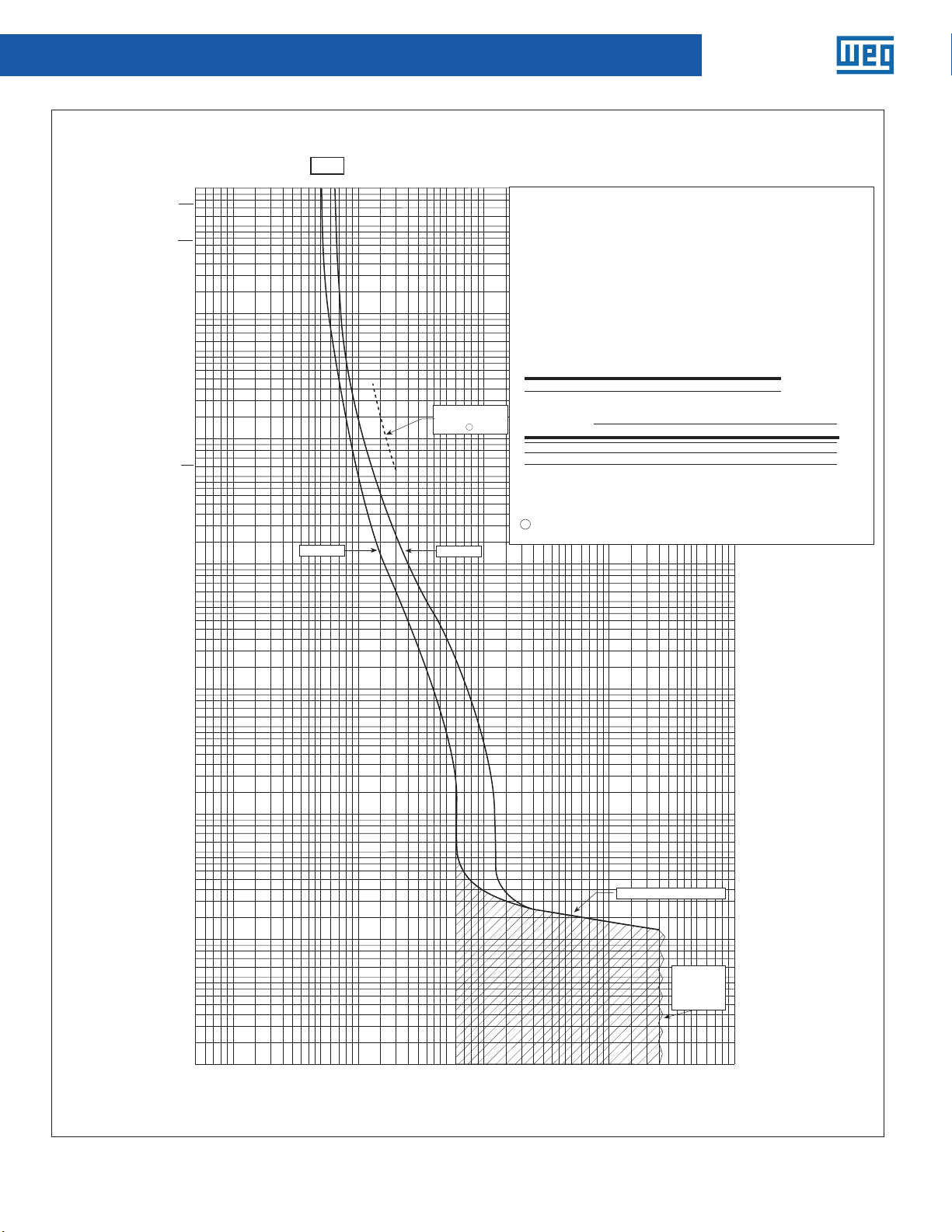
Molded-Case Circuit Breakers
UBW Time Current Curves
225 L
Effective September 2015
CURRENT IN AMPERES
CURRENT IN AMPERES
10,000
2 HOURS
5,000
1 HOUR
3,000
2,000
1,000
1 MINUTE
15A
8060 9070504030201 0 9 8 75 6
100
400
300
200
500
300
200
1000
800
600
900
700
500
Circuit breaker time/current curves
Series C® F-frame circuit breakers
Series C F-frame circuit breakers
Catalog type FDC circuit breaker, two-, three- and four-poles.
For application and coordination purposes only.
For application and coordination purposes only. Based on 40°C ambient, cold start.
Based on 40˚C ambient, cold start. Connected with four (4) feet of
rated wire (60˚C up to 125A, 75˚C above 125A) per terminal.
Connected with four (4) feet of rated wire (60°C up to 125A, 75°C above 125A) per
Tested in open air with current in all poles.
terminal. Tested in open air.
Maximum Vac: 600 at 50/60 Hz
Maximum Vac: 600 at 50/60 Hz
Maximum Vdc: 250
Maximum Vdc: 250
Breaker rating
Continuous amperes Instantaneous trip amperes
Breaker rating
15A See curve
Continuous amperes Instantaneous trip, amperes
Interrupting rating (UL/CSA listed)
Breaker
Symmetrical Rms amperes (KA) Amps (KA)
15A See curve
type
@ 240 Vac @ 480 Vac @ 600 Vac 250 Vdc
200FDC 100 35 22
Interrupting Rating (UL/CSA Listed)
1
Single-pole test data at 25˚C based on NEMA procedures
(AB
circuit breakers.
Breaker Type
L
Symmetrical RMS amperes (kA) Amps (KA)
4-2003) for verifying performance of molded case
@240Vac @480Vac @600Vac 250Vdc
200 100 35 22
2 HOURS
1 HOUR
5,000
3,000
2,000
1,000
500
300
200
Notes:
100
50
30
20
Maximum singlepole trip times
1
at 25°C
1 Single-pole test data at 25°C based on NEMA procedures (AB 4-2003) for verifying
performance of molded case circuit breakers.
.02
100
1 MINUTE
50
30
20
600V
10
Minimum
5
3
2
1
Maximum
30,000
20,000
10,000
480V
80,000
60,000
70,000
50,000
40,000
.01
.005
240V
.003
.002
90,000
100,000
200,000
10
5
3
TIME IN SECOND S
2
1
.5
.3
.2
.1
.05
.03
.02
.01
.005
.003
.002
.001
.005
.003
.002
.001
.5
TIME IN SECOND S
.3
.2
.1
.05
.03
.02
.01
60
40
20
56
987
10
30
80
7050
90
200
100
500
700
800
600
400
300
900
2000
1000
5000
4000
3000
Maximum interrupting time
7000
8000
6000
9000
10000
Interrupting
rating
determines
end of curve
(see above)
Data subject to change without notice. UBW Technical Manual | 7
Page 8
Molded-Case Circuit Breakers
Proof 1 — October 20, 2015 10:24 PM
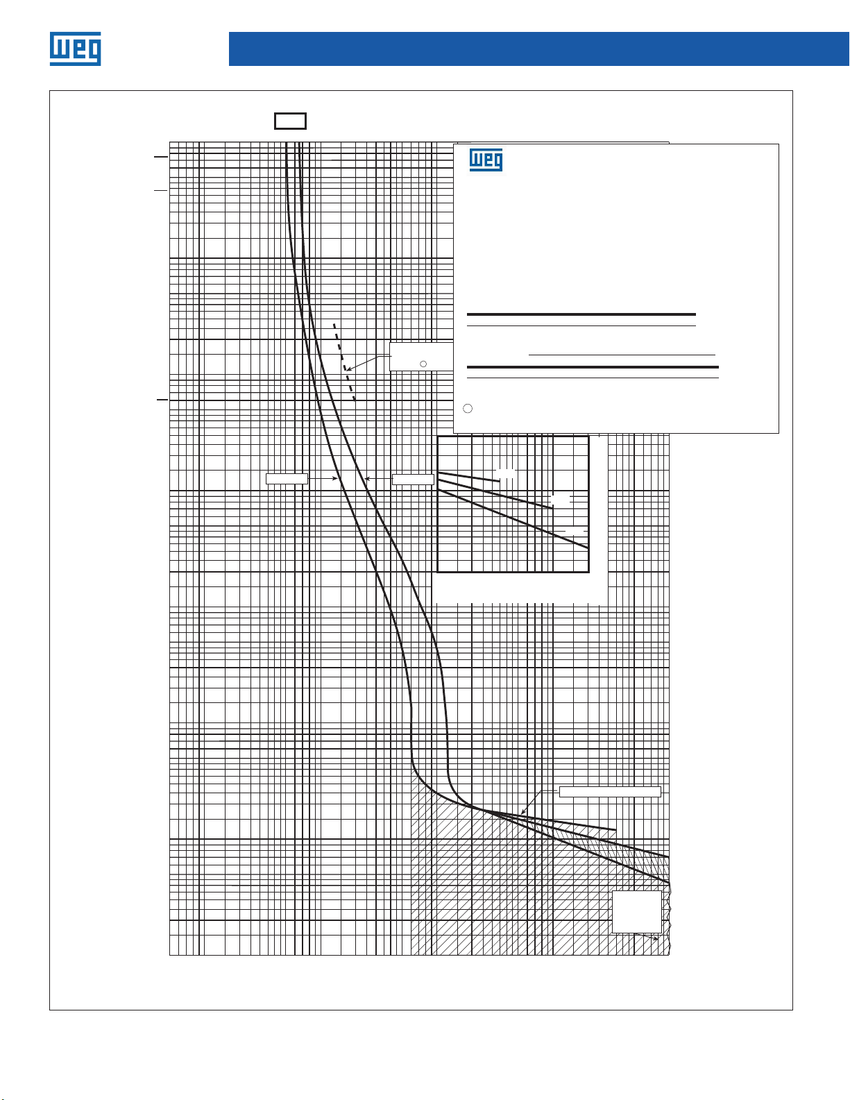
UBW Time Current Curves
225N/H
10,000
2 HOURS
5,000
1 HOUR
3,000
2,000
1,000
500
300
200
100
50
1 MINUTE
30
20
20A
CURRENT IN AMPERES
8060 9070504030201 0 9 8 75 6
100
Maximum singlepole trip times
at 25°C
1000
800
600
900
700
500
400
300
200
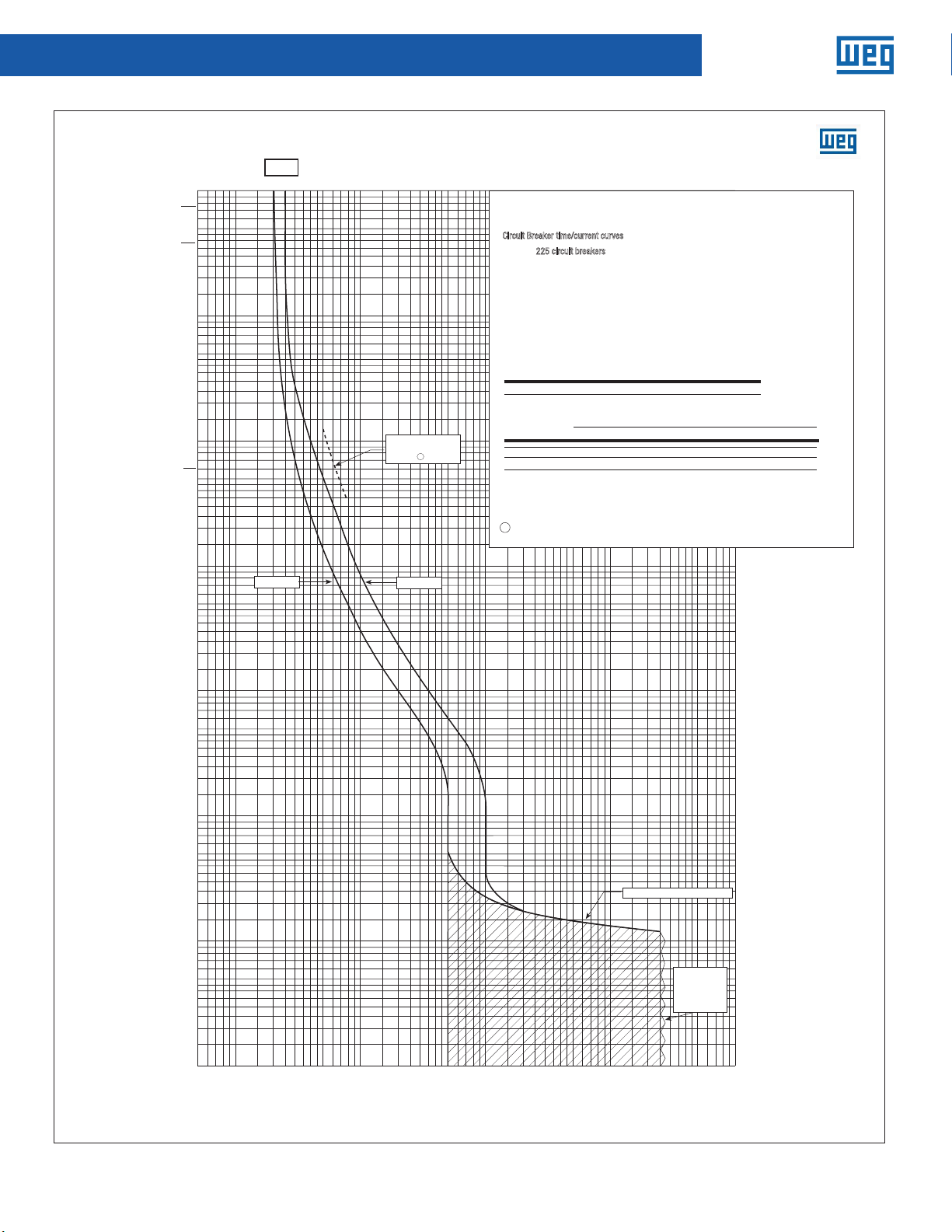
Circuit Breaker time/current curves
Series
For application and coordination purposes only. Based on 40°C ambient, cold start.
Connected with four (4) feet of rated wire (60°C up to 125A, 75°C above 125A) per
terminal. Tested in open air.
Maximum Vac: 600 at 50/60 Hz
Maximum Vdc: 250
Breaker rating
Continuous amperes Instantaneous trip, amperes
20A See curve
Interrupting Rating (UL/CSA Listed)
Breaker Type
1
N
H
Notes:
1 Single-pole test data at 25°C based on NEMA procedures (AB 4-2003) for verifying
performance of molded case circuit breakers.
4000
3000
2000
Series C® F-frame circuit breakers
Catalog types ED, EHD, FDB, FD and HFD circuit breakers, two-, three-
2
25 circuit breakers
Based on 40˚C ambient, cold start. Connected with four (4) feet of
Tested
Maximum Vac: 600 at 50/60 Hz
Maximum Vdc: 250
Breaker rating
Continuous amperes Instantaneous trip amperes
20A See curve
Interrupting rating (UL/CSA listed)
Breaker
Symmetrical Rms amperes (KA) Amps (KA)
@ 240 Vac @ 480 Vac @ 600 Vac 250 Vdc
type
18
EHD
18
FDB
65
FD
100
HFD
ED
65 —
1
Single-pole test data at 25˚C based on NEMA procedures
(AB
4-2003
circuit breakers.
10000
8000
6000
9000
7000
5000
time/current curves
5,000
3,000
2,000
1,000
500
125 Vdc
14
—
14
14
35
18
65
25
) for verifying performance of molded case
Symmetrical RMS amperes (kA)
@240Vac @480Vac @600Vac 250Vac
65 35 18 10
100 65 25 22
—
—
10
10
—
300
—
10
—
22
10
—
200
100
50
30
20
2 HOURS
1 HOUR
10
5
3
2
1
.5
TIME IN SECONDS
.3
.2
.1
.05
.03
.02
.01
.005
.003
.002
Minimum
Maximum
Maximum interrupting time
Interrupting
rating
determines
end of curve
(see above)
10
5
3
TIME IN SECONDS
2
1
.5
.3
.2
.1
.05
.03
.02
.01
.005
.003
.002
.001
56
20
987
10
60
40
80
7050
30
90
200
100
500
700
800
600
900
400
300
CURRENT IN AMPERES
1000
2000
3000
4000
5000
6000
7000
8000
9000
10000
.001
8 Data subject to change without notice.
Page 9
UBW Time Current Curves
225 L
Series C
F-Frame
CURRENT IN AMPERES
10,000
CURRENT IN AMPERES
Proof 1 — October 20, 2015 10:24 PM
2 HOURS
5,000
1 HOUR
3,000
2,000
1,000
500
300
200
100
50
1 MINUTE
30
20
10
5
3
2
1
20A
Minimum
8060 9070504030201 0 9 8 75 6
100
Maximum singlepole trip times
at 25°C
300
200
1
Maximum
Molded-Case Circuit Breakers
10000
8000
6000
9000
7000
5000
4000
3000
2000
1000
800
600
900
700
500
400
time/current curves
Series C F-frame circuit breakers
Catalog type FDC circuit breaker, two-, three- and four-poles.
Circuit breaker time/current curves
For application and coordination purposes only.
Series C F-frame circuit breakers
Based on 40˚C ambient, cold start. Connected with four (4) feet of
rated wire (60˚C up to 125A, 75˚C above 125A) per terminal.
For application and coordination purposes only. Based on 40°C ambient, cold start.
Maximum Vac: 600 at 50/60 Hz
Maximum Vdc: 250
Connected with four (4) feet of rated wire (60°C up to 125A, 75°C above 125A) per
terminal. Tested in open air.
Breaker rating
Continuous amperes Instantaneous trip amperes
Maximum Vac: 600 at 50/60 Hz
20A See curve
Maximum Vdc: 250
Interrupting rating (UL/CSA listed)
Breaker
Symmetrical Rms amperes (KA) Amps (KA)
Breaker rating
type
@ 240 Vac @ 480 Vac @ 600 Vac 250 Vdc
200FDC 100 35 22
Continuous amperes Instantaneous trip, amperes
1
Single-pole test data at 25˚C based on NEMA procedures
20A See curve
4-2003) for verifying performance of molded case
(AB
circuit breakers.
Interrupting Rating (UL/CSA Listed)
Breaker Type
L
Symmetrical RMS amperes (kA) Amps (KA)
@240Vac @480Vac @600Vac 250Vdc
200 100 35 22
Notes:
1 Single-pole test data at 25°C based on NEMA procedures (AB 4-2003) for verifying
performance of molded case circuit breakers.
.02
600V
480V
80,000
60,000
70,000
50,000
40,000
30,000
20,000
10,000
.01
.005
240V
.003
.002
90,000
100,000
200,000
2 HOURS
1 HOUR
5,000
3,000
2,000
1,000
500
300
200
100
1 MINUTE
50
30
20
10
5
3
TIME IN SECOND S
2
1
.005
.003
.002
.001
.5
TIME IN SECOND S
.3
.2
.1
.05
.03
.02
.01
60
40
20
56
987
10
30
80
7050
90
200
100
500
700
800
600
900
400
300
1000
2000
3000
4000
5000
Maximum interrupting time
7000
8000
6000
9000
10000
Interrupting
rating
determines
end of curve
(see above)
.5
.3
.2
.1
.05
.03
.02
.01
.005
.003
.002
.001
Data subject to change without notice. UBW Technical Manual | 9
Page 10

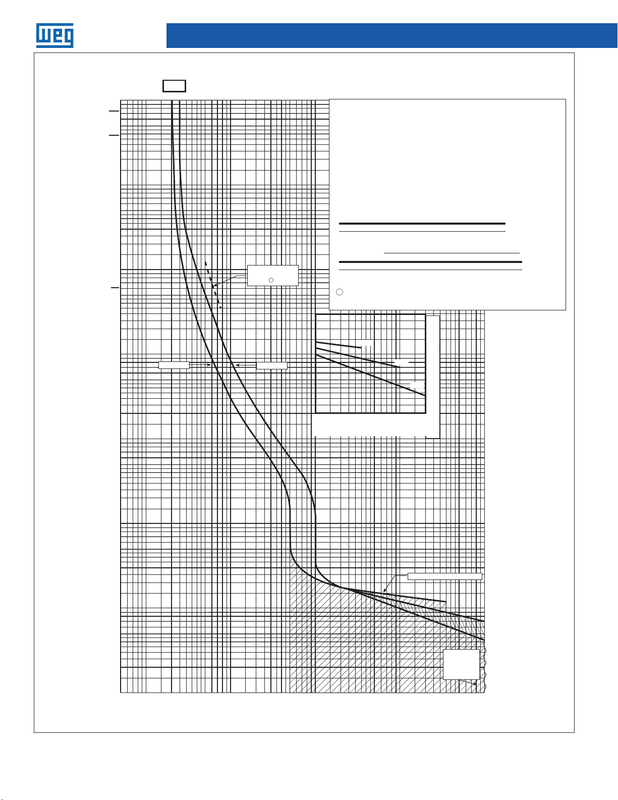
Molded-Case Circuit Breakers
Time Current Curves
225 N., H.
30A
10,000
2 HOURS
5,000
1 HOUR
3,000
2,000
1,000
500
300
200
100
50
1 MINUTE
30
20
CURRENT IN AMPERES
8060 9070504030201 0 9 8 75 6
100
400
300
200
1000
800
600
900
700
500
2000
3000
4000
Circuit breaker time/current curves
Series C® F-frame circuit breakers
Catalog types ED, EHD, FDB, FD and HFD circuit breakers, two-, three-
and four-poles.
Circuit breaker time/current curves
For application and coordination purposes only.
225 circuit breakers
Based on 40˚C ambient, cold start. Connected with four (4) feet of
Tested in open air with current in all poles.
For application and coordination purposes only. Based on 40°C ambient, cold start.
Maximum Vac: 600 at 50/60 Hz
Connected with four (4) feet of rated wire (60°C up to 125A, 75°C above 125A) per
Maximum Vdc: 250
terminal. Tested in open air.
Breaker Rating
Continuous amperes Instantaneous trip amperes
Maximum Vac: 600 at 50/60 Hz
30A See curve
Maximum Vdc: 250
Interrupting rating (UL/CSA listed)
Symmetrical RMS amperes (KA) Amps (KA)
Breaker
@ 240 Vac @ 480 Vac @ 600 Vac 250 Vdc 125 Vdc
type
18
EHD
18
FDB
65
FD
100
HFD
65 —
ED
1
Single-pole test data at 25˚C based on NEMA procedures
4-2003
) for verifying performance of molded case
(AB
circuit breakers.
Maximum singlepole trip times
1
at 25°C
Breaker rating
Continuous amperes Instantaneous trip, amperes
30A See curve
Interrupting Rating (UL/CSA Listed)
Breaker Type
N
H
10000
8000
6000
9000
7000
5000
5,000
125A, 75˚C above 125A) per terminal.
14
—
14
35
65
Symmetrical RMS amperes (kA)
@240Vac @480Vac @600Vac 250Vac
65 35 18 10
100 65 25 22
10
14
10
18
10
25
22
—
—
3,000
2,000
1,000
500
—
—
—
300
—
10
200
100
50
2 HOURS
1 HOUR
1 MINUTE
Notes:
1 Single-pole test data at 25°C based on NEMA procedures (AB 4-2003) for verifying
performance of molded case circuit breakers.
30
20
10
5
3
2
1
.5
TIME IN SECONDS
.3
.2
.1
.05
.03
.02
.01
.005
.003
.002
Minimum
Maximum
Maximum interrupting time
Interrupting
rating
determines
end of curve
(see above)
10
5
3
TIME IN SECONDS
2
1
.5
.3
.2
.1
.05
.03
.02
.01
.005
.003
.002
.001
56
20
987
10
60
40
80
30
7050
90
200
100
500
700
800
600
900
400
300
CURRENT IN AMPERES
1000
2000
3000
4000
5000
6000
7000
8000
9000
10000
.001
10 Data subject to change without notice.
Page 11

UBW Time Current Curves
225 L
Series C
F-Frame
CURRENT IN AMPERES
10,000
CURRENT IN AMPERES
Proof 1 — October 20, 2015 10:24 PM
2 HOURS
5,000
1 HOUR
3,000
2,000
1,000
500
300
200
100
50
1 MINUTE
30
20
10
5
3
2
1
30A
Minimum
Molded-Case Circuit Breakers
8060 9070504030201 0 9 8 75 6
100
400
300
200
1000
800
600
900
700
500
4000
3000
2000
10000
8000
6000
9000
7000
5000
time/current curves
Series C F-frame circuit breakers
Catalog type FDC circuit breaker, two-, three- and four-poles.
Circuit breaker time/current curves
For application and coordination purposes only.
Series C F-frame circuit breakers
Based on 40˚C ambient, cold start. Connected with four (4) feet of
rated wire (60˚C up to 125A, 75˚C above 125A) per terminal.
For application and coordination purposes only. Based on 40°C ambient, cold start.
Maximum Vac: 600 at 50/60 Hz
Connected with four (4) feet of rated wire (60°C up to 125A, 75°C above 125A) per
Maximum Vdc: 250
terminal. Tested in open air.
Breaker rating
Continuous amperes Instantaneous trip amperes
Maximum Vac: 600 at 50/60 Hz
30A See curve
Maximum Vdc: 250
Interrupting rating (UL/CSA listed)
Breaker
Symmetrical Rms amperes (KA) Amps (KA )
Breaker rating
@ 240 Vac @ 480 Vac @ 600 Vac 250 Vdc
type
200FDC 100 35 22
Continuous amperes Instantaneous trip, amperes
1
Single-pole test data at 25˚C based on NEMA procedures
30A See curve
(AB
4-2003) for verifying performance of molded case
circuit breakers.
Maximum singlepole trip times
1
at 25°C
Interrupting Rating (UL/CSA Listed)
Breaker Type
L
Notes:
1 Single-pole test data at 25°C based on NEMA procedures (AB 4-2003) for verifying
performance of molded case circuit breakers.
Symmetrical RMS amperes (kA) Amps (KA)
@240Vac @480Vac @600Vac 250Vdc
200 100 35 22
.02
600V
.01
.005
240V
.003
.002
90,000
100,000
200,000
Maximum
480V
80,000
60,000
70,000
50,000
40,000
30,000
20,000
10,000
2 HOURS
1 HOUR
5,000
3,000
2,000
1,000
500
300
200
100
1 MINUTE
50
30
20
10
5
3
TIME IN SECOND S
2
1
.005
.003
.002
.001
.5
TIME IN SECOND S
.3
.2
.1
.05
.03
.02
.01
60
40
20
56
987
10
30
80
7050
90
200
100
500
700
800
600
900
400
300
1000
4000
3000
2000
Maximum interrupting time
7000
8000
6000
9000
5000
10000
Interrupting
rating
determines
end of curve
(see above)
.5
.3
.2
.1
.05
.03
.02
.01
.005
.003
.002
.001
Data subject to change without notice. UBW Technical Manual | 11
Page 12
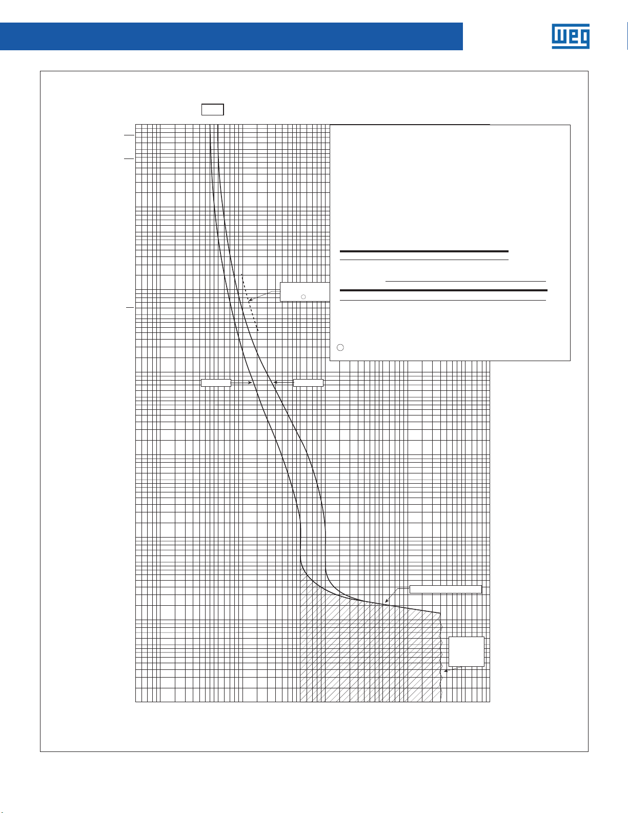
Molded-Case Circuit Breakers
Time Current Curves
225 N/H
10,000
2 HOURS
5,000
1 HOUR
3,000
2,000
1,000
500
300
200
100
50
1 MINUTE
30
20
10
5
40A
8060 9070504030201 0 9 8 75 6
100
CURRENT IN AMPERES
600
500
400
300
200
Maximum singlepole trip times
1
at 25°C
Minimum Maximum
10000
8000
6000
9000
7000
5000
4000
3000
2000
1000
800
900
700
Circuit breaker time/current curves
Catalog types ED, EHD, FDB, FD and HFD circuit breakers, two-, three -
and four-poles.
Circuit breaker time/current curves
For application and coordination purposes only.
Series C F-frame circuit breakers
Based on 40˚C ambient, cold start. Connected with four (4) feet of
rated wire (60˚C up to 125A, 75˚C above 125A) per terminal.
Catalog Types: ED, HED FDB, FD and HFD circuit breakers, two-, three- and four-pole.
Tested in open air with current in all poles.
For application and coordination purposes only. Based on 40°C ambient, cold start.
Maximum Vac: 600 at 50/60 Hz
Connected with four (4) feet of rated wire (60°C up to 125A, 75°C above 125A) per
Maximum Vdc: 250
terminal. Tested in open air.
Breaker Rating
Continuous amperes Instantaneous trip amperes
Maximum Vac: 600 at 50/60 Hz
40A See curve
Maximum Vdc: 250
Interrupting rating (UL/CSA listed)
Symmetrical Rms amperes (KA) Amps (KA)
Breaker
Breaker rating
Continuous amperes Instantaneous trip, amperes
40A See curve
Interrupting Rating (UL/CSA Listed)
Breaker Type
N
H
@ 240 Vac @ 480 Vac @ 600 Vac 250 Vdc 125 Vdc
type
18
EHD
FDB
FD
HFD
ED
1
Single-pole test data at 25˚C based on NEMA procedures
4-2003
(AB
circuit breakers.
14
18
14
65
35
100
65
—
) for verifying performance of molded case
Symmetrical RMS amperes (kA)
@240Vac @480Vac @600Vac 250Vac
65 35 18 10
100 65 25 22
10
—
14
10
18
10
25
22
—
—
Notes:
1 Single-pole test data at 25°C based on NEMA procedures (AB 4-2003) for verifying
performance of molded case circuit breakers.
5,000
3,000
2,000
1,000
500
—
—
300
—
—
0156
200
100
50
30
20
10
5
2 HOURS
1 HOUR
1 MINUTE
3
2
1
.5
TIME IN SECONDS
.3
.2
.1
.05
.03
.02
.01
.005
.003
.002
.001
56
3
TIME IN SECONDS
2
1
.5
.3
.2
.1
.05
Maximum interrupting time
Interrupting
rating
determines
end of curve
(see above)
60
40
20
987
10
30
80
7050
90
200
100
500
700
800
600
900
400
300
CURRENT IN AMPERES
1000
2000
3000
4000
5000
6000
7000
8000
9000
10000
.03
.02
.01
.005
.003
.002
.001
12 Data subject to change without notice.
Page 13
Molded-Case Circuit Breakers
UBW Time Current Curves
225 L
CURRENT IN AMPERES
10,000
2 HOURS
5,000
1 HOUR
3,000
2,000
1,000
1 MINUTE
40A
100
8060 9070504030201 0 9 8 75 6
500
300
200
100
50
30
20
CURRENT IN AMPERES
600
500
400
300
200
Maximum singlepole trip times
1
at 25°C
700
time/current curves
Series C F-frame circuit breakers
Catalog type FDC circuit breaker, two-, three- and four-poles.
Circuit breaker time/current curves
225 circuit breaker
For application and coordination purposes only. Based on 40°C ambient, cold start.
Maximum Vac: 600 at 50/60 Hz
Connected with four (4) feet of rated wire (60°C up to 125A, 75°C above 125A) per
Maximum Vdc: 250
terminal. Tested in open air.
Breaker rating
Continuous amperes Instantaneous trip amperes
Maximum Vac: 600 at 50/60 Hz
40A See curve
Maximum Vdc: 250
Interrupting rating (UL/CSA listed)
Breaker
Breaker rating
type
Continuous amperes Instantaneous trip, amperes
1
Single-pole test data at 25˚C based on NEMA procedures
40A See curve
(AB
4-2003) for verifying performance of molded case
circuit breakers.
Interrupting Rating (UL/CSA Listed)
Breaker Type
L
cold start. Connected with four (4) feet of
75˚C above 125A) per terminal.
Symmetrical Rms amperes (KA) Amps (KA)
@ 240 Vac @ 480 Vac @ 600 Vac 250 Vdc
200FDC 100 35 22
Symmetrical RMS amperes (kA) Amps (KA)
@240Vac @480Vac @600Vac 250Vdc
200 100 35 22
Notes:
1 Single-pole test data at 25°C based on NEMA procedures (AB 4-2003) for verifying
performance of molded case circuit breakers.
.02
5,000
3,000
2,000
1,000
500
300
200
100
50
30
20
2 HOURS
1 HOUR
1 MINUTE
10000
8000
6000
9000
7000
5000
4000
3000
2000
1000
800
900
600V
10
Minimum Maximum
5
480V
240V
.01
.005
10
5
.005
.003
.002
.001
3
2
80,000
60,000
70,000
50,000
40,000
30,000
20,000
10,000
1
.5
TIME IN SECO NDS
.3
.2
.1
.05
.03
.02
.01
60
40
20
56
987
10
30
80
7050
90
200
100
500
700
800
600
400
300
900
1000
3000
2000
7000
8000
6000
5000
4000
.003
.002
90,000
100,000
200,000
Maximum interrupting time
Interrupting
rating
determines
end of curve
(see above)
9000
10000
3
2
1
.5
.3
.2
.1
.05
.03
.02
.01
.005
.003
.002
.001
TIME IN SECO NDS
Data subject to change without notice. UBW Technical Manual | 13
Page 14
Molded-Case Circuit Breakers
Time Current Curves
225 N., H.
10,000
2 HOURS
5,000
1 HOUR
3,000
2,000
1,000
500
300
200
100
50
1 MINUTE
30
20
10
5
50A
Minimum
CURRENT IN AMPERES
8060 9070504030201 0 9 8 75 6
100
200
400
300
Maximum singlepole trip times
at 25°C
1000
800
600
900
700
500
1
4000
3000
2000
Catalog types ED, EHD, FDB, FD and HFD circuit breakers, two-, three-
and four-poles.
Circuit breaker time/current curves
225 Circuit breaker
Based on 40˚C ambient, cold start. Connected with four (4) feet of
Tested in open air with current in all poles.
For application and coordination purposes only. Based on 40°C ambient, cold start.
Maximum Vac: 600 at 50/60 Hz
Connected with four (4) feet of rated wire (60°C up to 125A, 75°C above 125A) per
Maximum Vdc: 250
terminal. Tested in open air.
Breaker rating
Continuous amperes Instantaneous trip amperes
Maximum Vac: 600 at 50/60 Hz
50A See curve
Maximum Vdc: 250
Interrupting rating (UL/CSA listed)
Symmetrical Rms amperes (KA) Amps (KA)Breaker
Breaker rating
type @ 240 Vac @ 480 Vac @ 600 Vac 250 Vdc 125 Vdc
18
EHD
Continuous amperes Instantaneous trip, amperes
18
FDB
65
FD
50A See curve
100
HFD
ED
65
1
Single-pole test data at 25˚C based on NEMA procedures
Interrupting Rating (UL/CSA Listed)
4-2003
(AB
circuit breakers.
Breaker Type
FD
H
10000
8000
6000
9000
7000
5000
time/current curves
circuit breakers
14
--
10
14
14
35
18
65
25
—
) for verifying performance of molded case
—
Symmetrical RMS amperes (kA)
@240Vac @480Vac @600Vac 250Vac
65 35 18 10
100 65 25 22
—
10
—
—
10
—
22
10
—
5,000
3,000
2,000
1,000
500
300
200
100
50
2 HOURS
1 HOUR
1 MINUTE
Notes:
Maximum
1 Single-pole test data at 25°C based on NEMA procedures (AB 4-2003) for verifying
performance of molded case circuit breakers.
20
10
5
3
2
1
.5
TIME IN SECONDS
.3
.2
.1
.05
.03
.02
.01
.005
.003
.002
.001
56
3
TIME IN SECONDS
2
1
.5
.3
.2
.1
.05
Maximum interrupting time
Interrupting
rating
determines
end of curve
(see above)
60
40
20
987
10
30
80
7050
90
200
100
500
700
800
600
900
400
300
CURRENT IN AMPERES
1000
2000
3000
4000
5000
6000
7000
8000
9000
10000
.03
.02
.01
.005
.003
.002
.001
14 Data subject to change without notice.
Page 15
UBW Time Current Curves
225L
Series C
F-Frame
CURRENT IN AMPERES
Proof 1 — October 20, 2015 10:24 PM
10,000
2 HOURS
5,000
1 HOUR
3,000
2,000
1,000
500
300
200
100
50
1 MINUTE
30
20
10
50A
Minimum
8060 9070504030201 0 9 8 75 6
100
CURRENT IN AMPERES
600
500
400
300
200
Maximum singlepole trip times
at 25°C
Maximum
3000
2000
1000
800
900
700
Circuit breaker time/current curves
Catalog type FDC circuit breaker, two-, three- and four-poles.
Circuit breaker time/current curves
For application and coordination purposes only.
225 circuit breakers
rated wire (60˚C up to 125A, 75˚C above 125A) per terminal.
Maximum Vac: 600 at 50/60 Hz
For application and coordination purposes only. Based on 40°C ambient, cold start.
Maximum Vdc: 250
Connected with four (4) feet of rated wire (60°C up to 125A, 75°C above 125A) per
terminal. Tested in open air.
Breaker rating
Continuous amperes Instantaneous trip amperes
50A See curve
Maximum Vac: 600 at 50/60 Hz
Maximum Vdc: 250
Interrupting rating (UL/CSA listed)
Breaker
type
Breaker rating
Continuous amperes Instantaneous trip, amperes
1
Single-pole test data at 25˚C based on NEMA procedures
4-2003) for verifying performance of molded case
(AB
50A See curve
circuit breakers.
Interrupting Rating (UL/CSA Listed)
1
Breaker Type
L
Notes:
1 Single-pole test data at 25°C based on NEMA procedures (AB 4-2003) for verifying
performance of molded case circuit breakers.
Molded-Case Circuit Breakers
10000
8000
6000
9000
7000
5000
4000
circuit breakers
cold start. Connected with four (4) feet of
Symmetrical Rms amperes (KA) Amps (KA)
@ 240 Vac @ 480 Vac @ 600 Vac 250 Vdc
200FDC 100 35 22
Symmetrical RMS amperes (kA) Amps (KA)
@240Vac @480Vac @600Vac 250Vdc
200 100 35 22
.02
600V
.01
480V
2 HOURS
1 HOUR
5,000
3,000
2,000
1,000
500
300
200
100
1 MINUTE
50
30
20
10
.005
.003
.002
5
3
2
80,000
60,000
70,000
50,000
40,000
30,000
20,000
10,000
1
.5
TIME IN SECOND S
.3
.2
.1
.05
.03
.02
.01
.005
240V
.003
.002
90,000
100,000
200,000
Maximum interrupting time
Interrupting
rating
determines
end of curve
(see above)
5
3
1
.5
.3
.2
.1
.05
.03
.02
.01
.005
.003
.002
TIME IN SECOND S
2
.001
56
987
10
30
80
7050
90
200
100
500
700
800
600
400
300
900
1000
3000
2000
7000
8000
6000
9000
5000
4000
10000
60
40
20
.001
Data subject to change without notice. UBW Technical Manual | 15
Page 16

Molded-Case Circuit Breakers
Time Current Curves
225 N., H.
10,000
2 HOURS
5,000
1 HOUR
3,000
2,000
1,000
500
300
200
100
50
1 MINUTE
30
20
10
5
60A
Minimum
CURRENT IN AMPERES
8060 9070504030201 0 9 8 75 6
100
400
300
200
1000
800
600
900
700
500
2000
3000
4000
Circuit beake
Catalog types ED, EHD, FDB, FD and HFD circuit breakers, two-, three-
and four-poles.
Circuit breaker time/current curves
225 circuit breakers
Based on 40˚C ambient, cold start. Connected with four (4) feet of
oen air with current in all
For application and coordination purposes only. Based on 40°C ambient, cold start.
Maximum Vac: 600 at 50/60 Hz
Connected with four (4) feet of rated wire (60°C up to 125A, 75°C above 125A) per
Maximum Vdc: 250
terminal. Tested in open air.
Breaker rating
Continuous amperes Instantaneous trip amperes
Maximum Vac: 600 at 50/60 Hz
60A See curve
Maximum Vdc: 250
Interrupting rating (UL/CSA listed)
Breaker
Symmetrical Rms amperes (KA) Amps (KA)
Breaker rating
@ 240 Vac @ 480 Vac @ 600 Vac 250 Vdc 125 Vdc
type
18
EHD
Continuous amperes Instantaneous trip, amperes
18
FDB
65
FD
100
HFD
60A See curve
65
ED
1
Single-pole test data at 25˚C based on NEMA procedures
Interrupting Rating (UL/CSA Listed)
4-2003
Maximum singlepole trip times
1
at 25°C
(AB
circuit breakers.
Breaker Type
N
H
Notes:
1 Single-pole test data at 25°C based on NEMA procedures (AB 4-2003) for verifying
performance of molded case circuit breakers.
Maximum
10000
8000
6000
9000
7000
5000
time/current curves
125A, 75˚C above 125A) per terminal.
poles.
14
—
10
14
14
35
18
65
25
—
—
) for verifying performance of molded case
Symmetrical RMS amperes (kA)
@240Vac @480Vac @600Vac 250Vac
65 35 18 10
100 65 25 22
—
10
—
—
10
—
22
—
10
5,000
3,000
2,000
1,000
500
300
200
100
50
30
20
10
5
2 HOURS
1 HOUR
1 MINUTE
3
2
1
.5
TIME IN SECONDS
.3
.2
.1
.05
.03
.02
.01
.005
.003
.002
.001
56
3
TIME IN SECONDS
2
1
.5
.3
.2
.1
.05
Maximum interrupting time
Interrupting
rating
determines
end of curve
(see above)
60
40
20
987
10
30
80
7050
90
200
100
500
700
800
600
900
400
300
CURRENT IN AMPERES
1000
2000
3000
4000
5000
6000
7000
8000
9000
10000
.03
.02
.01
.005
.003
.002
.001
16 Data subject to change without notice.
Page 17

Effective September 2015
Series C
F-Frame
CURRENT IN AMPERES
CURRENT IN AMPERES
Proof 1 — October 20, 2015 10:24 PMProof 1 — October 20, 2015 10:24 PM
UBW Time Current Curves
225L
10,000
2 HOURS
5,000
1 HOUR
3,000
2,000
1,000
500
300
200
100
50
1 MINUTE
30
20
10
60A
1000
800
600
900
700
500
400
300
200
100
8060 9070504030201 0 9 8 75 6
Maximum single-
pole trip times
1
at 25°C
Minimum
Maximum
Molded-Case Circuit Breakers
10000
8000
6000
9000
7000
5000
4000
3000
2000
Circuit breaker time/current curves
Series C®F-frame circuit breakers
Catalog type FDC circuit breaker, two-, three- and four-poles.
Circuit breaker time/current curves
For application and coordination purposes only.
UBW 225L circuit breakers
rated wire (60˚C up to 125A, 75˚C above 125A) per terminal.
For application and coordination purposes only. Based on 40°C ambient, cold start.
Maximum Vac: 600 at 50/60 Hz
Maximum Vdc: 250
Connected with four (4) feet of rated wire (60°C up to 125A, 75°C above 125A) per
terminal. Tested in open air.
Breaker rating
Continuous amperes Instantaneous trip amperes
Maximum Vac: 600 at 50/60 Hz
60A See curve
Maximum Vdc: 250
Interrupting rating (UL/CSA listed)
Breaker
Breaker rating
type
Continuous amperes Instantaneous trip, amperes
1
Single-pole test data at 25˚C based on NEMA procedures
60A See curve
(AB
4-2003) for verifying performance of molded case
circuit breakers.
Interrupting Rating (UL/CSA Listed)
Breaker Type
L
cold start. Connected with four (4) feet of
Symmetrical Rms amperes (KA) Amps (KA)
@ 240 Vac @ 480 Vac @ 600 Vac 250 Vdc
200FDC 100 35 22
Symmetrical RMS amperes (kA) Amps (KA)
@240Vac @480Vac @600Vac 250Vdc
200 100 35 22
Notes:
1 Single-pole test data at 25°C based on NEMA procedures (AB 4-2003) for verifying
performance of molded case circuit breakers.
600V
480V
5,000
3,000
2,000
1,000
500
300
200
100
50
30
.02
.01
20
10
2 HOURS
1 HOUR
1 MINUTE
.005
.003
.002
5
3
2
80,000
60,000
70,000
50,000
40,000
30,000
20,000
10,000
1
.5
TIME IN SECONDS
.3
.2
.1
.05
.03
.02
.01
.005
240V
.003
.002
90,000
200,000
100,000
Maximum interrupting time
Interrupting
rating
determines
end of curve
(see above)
5
3
2
1
.5
.3
.2
.1
.05
.03
.02
.01
.005
.003
.002
TIME IN SECONDS
.001
56
987
10
30
80
7050
90
200
100
500
700
800
600
400
300
900
2000
1000
7000
8000
6000
9000
5000
4000
3000
10000
60
40
20
.001
Data subject to change without notice. UBW Technical Manual | 17
Page 18

Molded-Case Circuit Breakers
Time Current Curves
225 N., H.
10,000
2 HOURS
5,000
1 HOUR
3,000
2,000
1,000
500
300
200
100
50
1 MINUTE
30
20
10
5
70A
8060 9070504030201 0 9 8 75 6
Minimum
CURRENT IN AMPERES
100
Circuit breaker time/current curves
Series
Catalog types ED, EHD, FDB, FD and HFD circuit breakers, two-, three-
and four-poles.
Circuit breaker time/current curves
225 circuit breakers
Based on 40˚C ambient, cold start. Connected with four (4) feet of
rated wire (60˚C
Tested in
For application and coordination purposes only. Based on 40°C ambient, cold start.
Maximum Vac: 600 at 50/60 Hz
Connected with four (4) feet of rated wire (60°C up to 125A, 75°C above 125A) per
Maximum Vdc: 250
terminal. Tested in open air.
Breaker rating
Continuous amperes Instantaneous trip amperes
Maximum Vac: 600 at 50/60 Hz
70A See curve
Maximum Vdc: 250
Interrupting rating (UL/CSA listed)
Symmetrical Rms amperes (KA) Amps (KA)Breaker
Breaker rating
Maximum singlepole trip times
1
at 25°C
type @ 240 Vac @ 480 Vac @ 600Vac 250 Vdc 125 Vdc
18
EHD
Continuous amperes Instantaneous trip, amperes
FDB
FD
70A See curve
HFD
ED 65
1
Single-pole test data at 25˚C based on NEMA procedures
Interrupting Rating (UL/CSA Listed)
(AB
circuit breakers.
Breaker Type
N
H
14
18
14
65
35
100
65
——
) for verifying performance of molded case
4-2003
Symmetrical RMS amperes (kA)
@240Vac @480Vac @600Vac 250Vac
65 35 18 10
100 65 25 22
10
—
14
18
25
—
10
—
—
10
—
22
10
Notes:
1 Single-pole test data at 25°C based on NEMA procedures (AB 4-2003) for verifying
performance of molded case circuit breakers.
5,000
3,000
2,000
1,000
500
300
200
100
50
30
20
2 HOURS
1 HOUR
1 MINUTE
10000
8000
6000
9000
7000
5000
4000
3000
2000
1000
800
600
900
700
500
400
300
200
Maximum
10
5
3
2
1
.5
TIME IN SECONDS
.3
.2
.1
.05
.03
.02
.01
.005
.003
.002
.001
56
3
TIME IN SECONDS
2
1
.5
.3
.2
.1
.05
Maximum interrupting time
Interrupting
rating
determines
end of curve
(see above)
60
40
20
987
10
30
80
7050
90
200
100
500
700
800
600
900
400
300
CURRENT IN AMPERES
1000
2000
3000
4000
5000
6000
7000
8000
9000
10000
.03
.02
.01
.005
.003
.002
.001
18 Data subject to change without notice.
Page 19

UBW Time Current Curves
225L
Series C
F-Frame
CURRENT IN AMPERES
Proof 1 — October 20, 2015 10:24 PM
Molded-Case Circuit Breakers
10,000
2 HOURS
5,000
1 HOUR
3,000
2,000
1,000
500
300
200
100
50
1 MINUTE
30
20
10
5
70A
8060 907050
100
200
500
400
300
Maximum singlepole trip times
at 25°C
100,000
80,000
60,000
90,000
70,000
50,000
40,000
30,000
1000
800
600
900
700
1
3000
2000
8000
6000
9000
7000
5000
4000
20,000
10000
Circuit breaker time/current curves
Catalog type FDC circuit breaker, two-, three- and four-poles.
Circuit breaker time/current curves
For application and coordination purposes only.
225 L
Maximum Vac: 600 at 50/60 Hz
For application and coordination purposes only. Based on 40°C ambient, cold start.
Maximum Vdc: 250
Connected with four (4) feet of rated wire (60°C up to 125A, 75°C above 125A) per
terminal. Tested in open air.
Breaker rating
Continuous amperes Instantaneous trip amperes
70A See curve
Maximum Vac: 600 at 50/60 Hz
Maximum Vdc: 250
Interrupting rating (UL/CSA listed)
Breaker
type
Breaker rating
Continuous amperes Instantaneous trip, amperes
1
Single-pole test data at 25˚C based on NEMA procedures
(AB
70A See curve
circuit breakers.
Interrupting Rating (UL/CSA Listed)
Breaker Type
L
circuit breakers
circuit breakers
125A,
Symmetrical Rms amperes (KA) Amps (KA)
@ 240 Vac @ 480 Vac @ 600 Vac 250 Vdc
200FDC 100 35 22
4-2003) for verifying performance of molded case
Symmetrical RMS amperes (kA) Amps (KA)
@240Vac @480Vac @600Vac 250Vdc
(4) feet of
200 100 35 22
Notes:
1 Single-pole test data at 25°C based on NEMA procedures (AB 4-2003) for verifying
performance of molded case circuit breakers.
2 HOURS
1 HOUR
5,000
3,000
2,000
1,000
500
300
200
100
1 MINUTE
50
30
20
10
5
.005
.003
.002
.001
3
Minimum
2
1
.5
TIME IN SECO NDS
.3
.2
.1
.05
.03
.02
Maximum
Maximum interrupting ti me
3
TIME IN SECO NDS
2
1
.5
.3
.2
.1
.05
.03
.02
600V
.01
480V
.01
.005
240V
.003
.002
60
80
7050
90
200
100
500
700
800
600
900
400
300
1000
3000
2000
CURRENT IN AMPERES
7000
8000
6000
9000
5000
4000
10000
30,000
20,000
80,000
60,000
90,000
70,000
50,000
40,000
100,000
200,000
.001
Data subject to change without notice. UBW Technical Manual | 19
Page 20

Molded-Case Circuit Breakers
Time Current Curves
225 N., H.
10,000
2 HOURS
5,000
1 HOUR
3,000
2,000
1,000
500
300
200
100
50
1 MINUTE
30
20
10
5
80A
8060 9070504030201 0 9 8 75 6
CURRENT IN AMPERES
10000
8000
6000
9000
7000
5000
4000
3000
2000
1000
800
600
900
700
500
400
300
200
100
Series circuit breakers
Catalog types ED, EHD, FDB, FD and HFD circuit breakers, two-, three-
and four-poles.
Circuit breaker time/current curves
C F-frame circuit breakers
Based on 40˚C ambient, cold start. Connected with four (4) feet of
rated wire (60˚C
open air with current in all poles.
For application and coordination purposes only. Based on 40°C ambient, cold start.
Maximum Vac: 600 at 50/60 Hz
Connected with four (4) feet of rated wire (60°C up to 125A, 75°C above 125A) per
Maximum Vdc: 250
terminal. Tested in open air.
Breaker rating
Continuous amperes Instantaneous trip amperes
Maximum Vac: 600 at 50/60 Hz
80A See curve
Maximum Vdc: 250
Interrupting rating (UL/CSA listed)
Symmetrical Rms amperes (KA) Amps (KA)Breaker
type
Breaker rating
Maximum singlepole trip times
1
at 25°C
@ 240 Vac @ 480 Vac @ 600 Vac 250 Vdc 125 Vdc
18
EHD
Continuous amperes Instantaneous trip, amperes
18
FDB
65
FD
100
HFD
80A See curve
ED 65 — — — 10
1
Single-pole test data at 25˚C based on NEMA procedures
Interrupting Rating (UL/CSA Listed)
(AB
4-2003
) for verifying performance of molded case
circuit breakers.
Breaker Type
N
H
—
14
14
14
35
18
25
65
Symmetrical RMS amperes (kA)
@240Vac @480Vac @600Vac 250Vac
65 35 18 10
100 65 25 22
—
10
—
10
—
10
22
—
Notes:
1 Single-pole test data at 25°C based on NEMA procedures (AB 4-2003) for verifying
performance of molded case circuit breakers.
5,000
3,000
2,000
1,000
500
300
200
100
50
30
20
10
5
2 HOURS
1 HOUR
1 MINUTE
3
2
1
.5
TIME IN SECONDS
.3
.2
.1
.05
.03
.02
.01
.005
.003
.002
.001
56
3
Minimum
Maximum
Maximum interrupting time
Interrupting
rating
determines
end of curve
(see above)
60
40
20
987
10
30
80
7050
90
200
100
500
700
800
600
900
400
300
CURRENT IN AMPERES
1000
2000
3000
4000
5000
6000
7000
8000
9000
10000
TIME IN SECONDS
2
1
.5
.3
.2
.1
.05
.03
.02
.01
.005
.003
.002
.001
20 Data subject to change without notice.
Page 21

Molded-Case Circuit Breakers
Effective September 2015
Series C
F-Frame
CURRENT IN AMPERES
Proof 1 — October 20, 2015 10:24 PMProof 1 — October 20, 2015 10:24 PM
UBW Time Current Curves
225L
10,000
2 HOURS
5,000
1 HOUR
3,000
2,000
1,000
500
300
200
100
50
1 MINUTE
30
20
10
8060 907050
100
80A
1000
800
600
900
700
500
400
300
200
Maximum singlepole trip times
1
at 25°C
CURRENT IN AMPERES
6000
5000
4000
3000
2000
8000
9000
7000
10000
Circuit breaker time/current curves
Series C F-frame circuit breaker
Catalog type FDC circuit breaker, two-, three- and four-poles.
Circuit breaker time/current curves
UBW 225L current curves
For application and coordination purposes only. Based on 40°C ambient, cold start.
Connected with four (4) feet of rated wire (60°C up to 125A, 75°C above 125A) per
terminal. Tested in open air.
Maximum Vac: 600 at 50/60 Hz
Maximum Vdc: 250
Breaker rating
Continuous amperes Instantaneous trip, amperes
80A See curve
Interrupting Rating (UL/CSA Listed)
Breaker Type
L
and coordination purposes only.
rated wire (60˚C up to 125A, 75˚C above 125A) per terminal.
Tested in open air with current in all poles.
Maximum Vac: 600 at 50/60 Hz
Maximum Vdc: 250
Breaker rating
Continuous amperes Instantaneous trip amperes
80A See curve
Interrupting rating (UL/CSA listed)
Breaker
type
1
Single-pole test data at 25˚C based on NEMA procedures
4-2003) for verifying performance of molded case
(AB
circuit breakers.
cold start. Connected with four (4) feet of
Symmetrical Rms amperes (KA) Amps (KA)
@ 240 Vac @ 480 Vac @ 600 Vac 250 Vdc
200FDC 100 35 22
Symmetrical RMS amperes (kA) Amps (KA)
@240Vac @480Vac @600Vac 250Vdc
200 100 35 22
Notes:
1 Single-pole test data at 25°C based on NEMA procedures (AB 4-2003) for verifying
performance of molded case circuit breakers.
5,000
3,000
2,000
1,000
500
300
200
100
50
30
20
10
2 HOURS
1 HOUR
1 MINUTE
100,000
80,000
60,000
90,000
70,000
50,000
40,000
30,000
20,000
.005
.003
.002
5
3
2
1
.5
TIME IN SECOND S
.3
.2
.1
.05
.03
.02
MaximumMinimum
Maximum interrupting time
5
3
TIME IN SECONDS
2
1
.5
.3
.2
.1
.05
.03
.02
600V
.01
480V
.01
.005
240V
.003
.002
.001
60
80
7050
90
200
100
500
700
800
600
400
300
900
1000
3000
2000
7000
8000
6000
9000
5000
4000
10000
30,000
20,000
80,000
60,000
90,000
70,000
50,000
40,000
100,000
200,000
.001
Data subject to change without notice. UBW Technical Manual | 21
Page 22

Molded-Case Circuit Breakers
Time Current Curves
225 N., H.
10,000
2 HOURS
5,000
1 HOUR
3,000
2,000
1,000
500
300
200
100
50
1 MINUTE
30
20
10
5
90A
8060 9070504030201 0 9 8 75 6
Minimum
CURRENT IN AMPERES
10000
8000
6000
9000
7000
5000
4000
3000
2000
1000
800
600
900
700
500
400
300
200
100
Circuit breaker time/current curves
225 circuit breakers
For application and coordination purposes only. Based on 40°C ambient, cold start.
600 at 50/60 Hz
Connected with four (4) feet of rated wire (60°C up to 125A, 75°C above 125A) per
250
terminal. Tested in open air.
Maximum Vac: 600 at 50/60 Hz
Maximum Vdc: 250
Symmetrical Rms amperes (KA) Amps (KA)
Breaker rating
@ 240 Vac @ 480 Vac @ 600 Vac 250 Vdc 125 Vdc
18
14
—
10
—
10
—
—
10
—
22
Maximum singlepole trip times
1
at 25°C
Continuous amperes Instantaneous trip, amperes
18
14
65
90A See curve
100
Interrupting Rating (UL/CSA Listed)
) for verifying performance of molded case
Breaker Type
N
H
14
35
18
65
25
Symmetrical RMS amperes (kA)
@240Vac @480Vac @600Vac 250Vac
65 35 18 10
100 65 25 22
Notes:
1 Single-pole test data at 25°C based on NEMA procedures (AB 4-2003) for verifying
performance of molded case circuit breakers.
Maximum
5,000
3,000
2,000
1,000
500
300
200
100
50
30
20
10
5
2 HOURS
1 HOUR
1 MINUTE
3
2
1
.5
TIME IN SECONDS
.3
.2
.1
.05
.03
.02
.01
.005
.003
.002
.001
56
3
TIME IN SECONDS
2
1
.5
.3
.2
.1
.05
Maximum interrupting time
Interrupting
rating
determines
end of curve
(see above)
60
40
20
987
10
30
80
7050
90
200
100
500
700
800
600
900
400
300
CURRENT IN AMPERES
1000
2000
3000
4000
5000
6000
7000
8000
9000
10000
.03
.02
.01
.005
.003
.002
.001
22 Data subject to change without notice.
Page 23

Time Current Curves
225L
Series C
F-Frame
CURRENT IN AMPERES
Proof 1 — October 20, 2015 10:24 PM
Molded-Case Circuit Breakers
10,000
2 HOURS
5,000
1 HOUR
3,000
2,000
1,000
500
300
200
100
50
1 MINUTE
30
20
10
8060 907050
100
90A
400
300
200
1000
800
600
900
700
500
Maximum singlepole trip times
1
at 25°C
2000
3000
4000
5000
6000
7000
8000
9000
10000
20,000
100,000
80,000
60,000
90,000
70,000
50,000
40,000
30,000
Circuit breaker time/current curves
Series C F-frame circuit breakers
Catalog type FDC circuit breaker, two-, three- and four-poles.
Circuit breaker time/current curves
For application and coordination purposes only.
225L Circuit Breakers
rated wire (60˚C up to 125A, 75˚C above 125A) per terminal.
For application and coordination purposes only. Based on 40°C ambient, cold start.
Maximum Vac: 600 at 50/60 Hz
Maximum Vdc: 250
Connected with four (4) feet of rated wire (60°C up to 125A, 75°C above 125A) per
terminal. Tested in open air.
Breaker rating
Continuous amperes Instantaneous trip amperes
Maximum Vac: 600 at 50/60 Hz
100A See curve
Maximum Vdc: 250
Interrupting rating (UL/CSA listed)
Breaker
Breaker rating
Continuous amperes Instantaneous trip, amperes
90A See curve
Interrupting Rating (UL/CSA Listed)
Breaker Type
L
Symmetrical Rms amperes (KA) Amps (KA)
@ 240 Vac @ 480 Vac @ 600 Vac 250 Vdc
type
200FDC 100 35 22
1
Single-pole test data at 25˚C based on NEMA procedures
4-2003) for verifying performance of molded case
(AB
circuit breakers.
Symmetrical RMS amperes (kA) Amps (KA)
@240Vac @480Vac @600Vac 250Vdc
200 100 35 22
(4) feet of
Notes:
1 Single-pole test data at 25°C based on NEMA procedures (AB 4-2003) for verifying
performance of molded case circuit breakers.
2 HOURS
1 HOUR
5,000
3,000
2,000
1,000
500
300
200
100
1 MINUTE
50
30
20
10
.005
.003
.002
Minimum
5
3
2
1
.5
TIME IN SECO NDS
.3
.2
.1
.05
.03
.02
Maximum
Maximum interrupting time
5
3
TIME IN SECO NDS
2
1
.5
.3
.2
.1
.05
.03
.02
600V
.01
480V
.01
.005
240V
.003
.002
.001
60
80
7050
90
200
100
500
700
800
600
900
400
300
1000
3000
2000
CURRENT IN AMPERES
4000
5000
6000
7000
8000
9000
10000
20,000
80,000
60,000
200,000
100,000
90,000
70,000
50,000
40,000
30,000
.001
Data subject to change without notice. UBW Technical Manual | 23
Page 24

Molded-Case Circuit Breakers
Time Current Curves
225 N., H.
10,000
2 HOURS
5,000
1 HOUR
3,000
2,000
1,000
500
300
200
100
50
1 MINUTE
30
20
10
5
100A
8060 9070504030201 0 9 8 75 6
100
CURRENT IN AMPERES
600
500
400
300
200
Maximum singlepole trip times
at 25°C
1000
800
900
700
Circuit breaker time/current curves
®
F-frame circuit breakers
Series C
225 circuit breakers
Based on
rated wire (60˚C up to 125A, 75˚C above 125A) per terminal.
For application and coordination purposes only. Based on 40°C ambient, cold start.
Tested in open air with current in all poles.
Maximum Vac: 600 at 50/60 Hz
Connected with four (4) feet of rated wire (60°C up to 125A, 75°C above 125A) per
Maximum Vdc: 250
terminal. Tested in open air.
Breaker rating
Continuous amperes Instantaneous trip amperes
Maximum Vac: 600 at 50/60 Hz
100A See curve
Maximum Vdc: 250
Interrupting rating (UL/CSA listed)
Breaker
Symmetrical Rms amperes (KA) Amps (KA)
type
@ 240 Vac @ 480 Vac @ 600 Vac 250 Vdc 125 Vdc
Breaker rating
ED
65 — — — 10
EDB
22 — — — 10
Continuous amperes Instantaneous trip, amperes
EDS
42 — — — 10
EDH
100 — — — 10
100A See curve
EDC
200 — — — 10
EHD
18 14 — 10 —
FDB
18 14 14 10 —
FD
65 35 18 10 —
Interrupting Rating (UL/CSA Listed)
HFD
100 65 25 22 —
Single-pole test data at 25˚C based on NEMA procedures
1
(AB
4-2003
Breaker Type
1
circuit breakers.
N
H
Symmetrical RMS amperes (kA)
) for verifying performance of molded case
@240Vac @480Vac @600Vac 250Vac
65 35 18 10
100 65 25 22
Notes:
1 Single-pole test data at 25°C based on NEMA procedures (AB 4-2003) for verifying
performance of molded case circuit breakers.
MaximumMinimum
2 HOURS
1 HOUR
2,000
1,000
500
300
200
30
20
10
5
3
2
1
.5
TIME IN SECONDS
.3
.2
.1
.05
.03
.02
.01
.005
.003
.002
.001
56
3
TIME IN SECONDS
2
1
.5
.3
.2
.1
.05
Maximum interrupting time
Interrupting
rating
determines
end of curve
(see above)
60
40
20
987
10
30
80
7050
90
200
100
500
700
800
600
900
400
300
CURRENT IN AMPERES
1000
2000
3000
4000
5000
6000
7000
8000
9000
10000
.03
.02
.01
.005
.003
.002
.001
24 Data subject to change without notice.
Page 25

Molded-Case Circuit Breakers
Effective September 2015
Series C
F-Frame
CURRENT IN AMPERES
Proof 1 — October 20, 2015 10:24 PMProof 1 — October 20, 2015 10:24 PM
UBW Time Current Curves
225L
100
8060 907050
10,000
2 HOURS
5,000
1 HOUR
3,000
2,000
1,000
500
300
200
100
50
1 MINUTE
30
20
10
100A
1000
800
600
900
700
500
400
300
200
Maximum singlepole trip times
1
at 25°C
2000
3000
4000
5000
6000
7000
100,000
80,000
60,000
90,000
70,000
50,000
40,000
30,000
20,000
10000
8000
9000
Circuit breaker time/current curves
Series C®F-frame circuit breakers
Catalog type FDC circuit breaker, two-, three- and four-poles.
Circuit breaker time/current curves
225L Circuit Breakers
Based on 40˚C ambient, cold start. Connected with four (4) feet of
Tested in open air with current in all poles.
For application and coordination purposes only. Based on 40°C ambient, cold start.
Maximum Vac: 600 at 50/60 Hz
Connected with four (4) feet of rated wire (60°C up to 125A, 75°C above 125A) per
Maximum Vdc: 250
terminal. Tested in open air.
Breaker rating
Continuous amperes Instantaneous trip amperes
Maximum Vac: 600 at 50/60 Hz
100A See curve
Maximum Vdc: 250
Interrupting rating (UL/CSA listed)
Breaker rating
Breaker
Symmetrical Rms amperes (KA) Amps (KA)
@ 240 Vac @ 480 Vac @ 600 Vac 250 Vdc
type
Continuous amperes Instantaneous trip, amperes
100A See curve
Interrupting Rating (UL/CSA Listed)
Breaker Type
L
200FDC 100 35 22
1
Single-pole test data at 25˚C based on NEMA procedures
4-2003) for verifying performance of molded case
(AB
circuit breakers.
Symmetrical RMS amperes (kA) Amps (KA)
@240Vac @480Vac @600Vac 250Vdc
200 100 35 22
Notes:
1 Single-pole test data at 25°C based on NEMA procedures (AB 4-2003) for verifying
performance of molded case circuit breakers.
5,000
3,000
2,000
1,000
500
300
200
100
50
30
20
10
2 HOURS
1 HOUR
1 MINUTE
.005
.003
.002
Minimum
5
3
2
1
.5
TIME IN SECO NDS
.3
.2
.1
.05
.03
.02
Maximum
Maximum interrupting time
5
3
TIME IN SECO NDS
2
1
.5
.3
.2
.1
.05
.03
.02
600V
.01
480V
.01
.005
240V
.003
.002
.001
60
80
7050
90
200
100
500
700
800
600
900
400
300
1000
3000
2000
CURRENT IN AMPERES
4000
5000
6000
7000
8000
9000
10000
20,000
100,000
200,000
80,000
60,000
90,000
70,000
50,000
40,000
30,000
.001
Data subject to change without notice. UBW Technical Manual | 25
Page 26

Molded-Case Circuit Breakers
Time Current Curves
225 N., H.
10,000
2 HOURS
5,000
1 HOUR
3,000
2,000
1,000
500
300
200
100
50
1 MINUTE
30
20
10
5
8060 9070504030201 0 9 8 75 6
125A
100
CURRENT IN AMPERES
600
500
400
300
200
Maximum singlepole trip times
at 25°C
700
Circuit breaker time/current curves
®
F-frame circuit breakers
225 circuit breakers
For application and coordination purposes only. Based on 40°C ambient, cold start.
600 at 50/60 Hz
Connected with four (4) feet of rated wire (60°C up to 125A, 75°C above 125A) per
250
terminal. Tested in open air.
Maximum Vac: 600 at 50/60 Hz
Maximum Vdc: 250
Symmetrical Rms amperes (KA) Amps (KA)
@ 240 Vac @ 480 Vac @ 600 Vac 250 Vdc 125 Vdc
Breaker rating
65
—
—
22
—
Continuous amperes Instantaneous trip, amperes
125A See curve
Interrupting Rating (UL/CSA Listed)
4-2003
Breaker Type
1
N
H
— — 10
42
—
—
100
200
— —
18 14 14 10 —
65 35 18 10 —
100 65 25 22 —
Symmetrical RMS amperes (kA)
) for verifying performance of molded case
@240Vac @480Vac @600Vac 250Vac
65 35 18 10
100 65 25 22
—
—
—
—
—
—
10
Notes:
1 Single-pole test data at 25°C based on NEMA procedures (AB 4-2003) for verifying
performance of molded case circuit breakers.
MaximumMinimum
2 HOURS
5,000
1 HOUR
3,000
2,000
1,000
10
500
10
10
300
200
30
20
10
5
10000
8000
6000
9000
7000
5000
4000
3000
2000
1000
800
900
3
2
1
.5
TIME IN SECONDS
.3
.2
.1
.05
.03
.02
.01
.005
.003
.002
.001
56
3
TIME IN SECONDS
2
1
.5
.3
.2
.1
.05
Maximum interrupting t ime
Interrupting
rating
determines
end of curve
(see above)
60
40
20
987
10
30
80
7050
90
200
100
500
700
800
600
900
400
300
CURRENT IN AMPERES
1000
2000
3000
4000
5000
6000
7000
8000
9000
10000
.03
.02
.01
.005
.003
.002
.001
26 Data subject to change without notice.
Page 27

Molded-Case Circuit Breakers
Effective September 2015
Series C
F-Frame
CURRENT IN AMPERES
CURRENT IN AMPERES
Proof 1 — October 20, 2015 10:24 PMProof 1 — October 20, 2015 10:24 PM
UBW Time Current Curves
225L
8060 907050
10,000
2 HOURS
5,000
1 HOUR
3,000
2,000
1,000
500
300
200
100
50
1 MINUTE
30
20
10
125A
100
300
200
400
1000
800
600
900
700
500
Maximum singlepole trip times
1
at 25°C
2000
3000
4000
5000
7000
Circuit breaker time/current curves
Series C F-frame circuit breakers
Catalog type FDC circuit breaker, two-, three- and four-poles.
Circuit breaker time/current curves
For application and coordination purposes only.
UBW 225L Circuit Breakers
rated wire (60˚C up to 125A, 75˚C above 125A) per terminal.
Tested in open air with current in all poles.
Maximum Vac: 600 at 50/60 Hz
For application and coordination purposes only. Based on 40°C ambient, cold start.
Maximum Vdc: 250
Connected with four (4) feet of rated wire (60°C up to 125A, 75°C above 125A) per
terminal. Tested in open air.
Breaker rating
Continuous amperes Instantaneous trip amperes
125A See curve
Maximum Vac: 600 at 50/60 Hz
Maximum Vdc: 250
Interrupting rating (UL/CSA listed)
Breaker
type
Breaker rating
Continuous amperes Instantaneous trip, amperes
1
Single-pole test data at 25˚C based on NEMA procedures
4-2003) for verifying performance of molded case
(AB
125A See curve
circuit breakers.
Interrupting Rating (UL/CSA Listed)
Breaker Type
L
cold start. Connected with four (4) feet of
Symmetrical Rms amperes (KA) Amps (KA)
@ 240 Vac @ 480 Vac @ 600 Vac 250 Vdc
200FDC 100 35 22
Symmetrical RMS amperes (kA) Amps (KA)
@240Vac @480Vac @600Vac 250Vdc
200 100 35 22
100,000
80,000
60,000
90,000
70,000
50,000
40,000
30,000
20,000
10000
8000
6000
9000
Notes:
1 Single-pole test data at 25°C based on NEMA procedures (AB 4-2003) for verifying
performance of molded case circuit breakers.
5,000
3,000
2,000
1,000
500
300
200
100
50
30
20
10
2 HOURS
1 HOUR
1 MINUTE
.005
.003
.002
5
3
2
1
.5
TIME IN SECO NDS
.3
.2
.1
.05
.03
.02
MaximumMinimum
Maximum interrupting time
5
3
TIME IN SECO NDS
2
1
.5
.3
.2
.1
.05
.03
.02
600V
.01
480V
.01
.005
240V
.003
.002
.001
60
80
7050
90
200
100
500
700
800
600
400
300
900
1000
2000
3000
4000
5000
6000
7000
8000
9000
10000
20,000
100,000
200,000
80,000
60,000
90,000
70,000
50,000
40,000
30,000
.001
Data subject to change without notice. UBW Technical Manual | 27
Page 28

Molded-Case Circuit Breakers
Time Current Curves
225 N., H.
10,000
2 HOURS
5,000
1 HOUR
3,000
2,000
1,000
500
300
200
100
50
1 MINUTE
30
20
10
5
8060 9070504030201 0 9 8 75 6
150A
100
CURRENT IN AMPERES
600
500
400
300
200
Maximum singlepole trip times
at 25°C
1000
800
900
700
1
3000
Circuit breaker time/current curves
®
F-frame circuit breakers
225 circuit breakers
Catalog Types: ED, EDB, EDS, EDH, EDC, EHD, FDB, FD and HFD circuit breakers,
two-, three- and four-pole.
For application and coordination purposes only. Based on 40°C ambient, cold start.
Connected with four (4) feet of rated wire (60°C up to 125A, 75°C above 125A) per
terminal. Tested in open air.
Maximum Vac: 600 at 50/60 Hz
Maximum Vdc: 250
Breaker rating
Interrupting Rating (UL/CSA Listed)
Breaker Type
600 at 50/60 Hz
250
Symmetrical Rms amperes (KA) Amps (KA)
@ 240 Vac @ 480 Vac @ 600 Vac 250 Vdc 125 Vdc
65 — — — 10
22 — — — 10
Continuous amperes Instantaneous trip, amperes
42 — ——10
100 — — — 10
150A See curve
200 — — — 10
18 14 14 10 —
65 35 18 10 —
100 65 25 22 —
(AB
4-2003
circuit breakers.
N
H
Symmetrical RMS amperes (kA)
) for verifying performance of molded case
@240Vac @480Vac @600Vac 250Vac
65 35 18 10
100 65 25 22
Notes:
1 Single-pole test data at 25°C based on NEMA procedures (AB 4-2003) for verifying
performance of molded case circuit breakers.
MaximumMinimum
5,000
3,000
2,000
1,000
500
300
200
30
20
10
5
2 HOURS
1 HOUR
10000
8000
6000
9000
7000
5000
4000
3
2
1
.5
TIME IN SECONDS
.3
.2
.1
.05
.03
.02
.01
.005
.003
.002
.001
56
3
TIME IN SECONDS
2
1
.5
.3
.2
.1
.05
Maximum interrupting t ime
Interrupting
rating
determines
end of curve
(see above)
60
40
20
987
10
30
80
7050
90
200
100
500
700
800
600
900
400
300
CURRENT IN AMPERES
1000
2000
3000
4000
5000
6000
7000
8000
9000
10000
.03
.02
.01
.005
.003
.002
.001
28 Data subject to change without notice.
Page 29

UBW Time Current Curves
225L
Series C
F-Frame
CURRENT IN AMPERES
CURRENT IN AMPERES
Maximum single-
pole trip times
at 25°C
Maximum
trip time
Minimum
trip time
175 A
200 A
225 A
100
50
30
20
10
5
3
2
1
.5
.3
.2
.1
.05
.03
.02
.01
.005
.003
.002
.001
TIME IN SECO NDS
1,000
500
300
200
5,000
3,000
2,000
1 HOUR
1 MINUTE
2 HOURS
TIME IN SECO NDS
10,000
100
50
30
20
10
5
3
2
1
.5
.3
.2
.1
.05
.03
.02
.01
.005
.003
.002
.001
1,000
500
300
200
5,000
3,000
2,000
1 HOUR
1 MINUTE
2 HOURS
175–225A
Circuit breaker time/current curves
molded-case circuit breakers
Catalog types FD/HFD circuit breakers, two-, three- and four-poles.
For application and coordination purposes only.
Based on 40˚C ambient, cold start. Connected with four (4) feet of rated
wire (75˚C) per terminal. Tested in open air with current inall poles.
Maximum Vac: 600 at 50/60 Hz
Maximum Vdc: 250
Breaker rating
In amperes Instantaneous pick-up, amperes Rms
175 2400
200 2400
225 2400
Breaker
type
Symmetrical Rms amperes (kA), I
cu
FD
HFD
Fixed inverse– time overcurrent release.
Single-pole test data at 25 °C based on NEMA procedures (AB
4-2003)
for verifying performances of molded case circuit breakers.
Total operation time.
terrupting rating determines end of curve.
In this interruption region:
The curve is drawn for In = 200A. For Inπ 200A, the end points in this
region are displaced along the current-axis by a factor (200A/In)
240 Vac
Interrupting ratings
65
100
480 Vac
35
65
600 Vac
18
25
250 Vac
10
22
CURRENT IN MULTIPLES OF I
n
CURRENT IN MULTIPLES OF I
n
Notes:
9681 75 4 3 08012 60 907050403020
1000
800
600
900
700
500
400
300
200
100
9681 75 4 3 08012 60 907050403020
1000
800
600
900
700
500
400
300
200
100
1
2
3
4
Proof 1 — October 20, 2015 10:24 PMProof 1 — October 20, 2015 10:24 PM
Molded-Case Circuit Breakers
10,000
2 HOURS
5,000
1 HOUR
3,000
2,000
1,000
500
300
200
100
50
1 MINUTE
30
20
10
5
3
2
150A
8060 907050
100
Minimum
400
300
200
800
600
900
700
500
Maximum singlepole trip times
at 25°C
1000
1
8000
6000
9000
7000
5000
4000
3000
2000
Circuit breaker time/current curves
225L Circuit Breakers
For application and coordination purposes only. Based on 40°C ambient, cold start.
Connected with four (4) feet of rated wire (60°C up to 125A, 75°C above 125A) per
terminal. Tested in open air.
Maximum Vac: 600 at 50/60 Hz
Maximum Vdc: 250
Notes:
1 Single-pole test data at 25°C based on NEMA procedures (AB 4-2003) for verifying
Maximum
100,000
80,000
60,000
90,000
70,000
50,000
40,000
30,000
20,000
10000
Circuit breaker time/current curves
Series C®F-frame circuit breakers
Catalog type FDC circuit breaker, two-, three- and four-poles.
For application and coordination purposes only.
rated wire (60˚C up to 125A,
Maximum Vac: 600 at 50/60 Hz
Maximum Vdc: 250
Breaker rating
Continuous amperes Instantaneous trip amperes
150A See curve
Interrupting rating (UL/CSA listed)
Breaker
Breaker rating
type
Continuous amperes Instantaneous trip, amperes
1
150A See curve
Interrupting Rating (UL/CSA Listed)
Single-pole test data at 25˚C based on NEMA procedures
(AB
circuit breakers.
Breaker Type
L
performance of molded case circuit breakers.
Symmetrical Rms amperes (KA) Amps (KA)
@ 240 Vac @ 480 Vac @ 600 Vac 250 Vdc
200FDC 100 35 22
4-2003) for verifying performance of molded case
Symmetrical RMS amperes (kA) Amps (KA)
@240Vac @480Vac @600Vac 250Vdc
200 100 35 22
5,000
3,000
2,000
1,000
500
300
200
100
50
30
20
10
5
3
2
TIME IN SECO ND S
2 HOURS
1 HOUR
1 MINUTE
.005
.003
.002
.001
1
.5
TIME IN SECO ND S
.3
.2
1
.5
.3
.2
.1
.05
.03
.02
Maximum interrupting time
.1
.05
.03
.02
600V
.01
60
80
7050
90
200
100
500
700
800
600
400
300
900
1000
3000
2000
7000
8000
6000
9000
5000
4000
10000
30,000
20,000
480V
240V
80,000
60,000
90,000
70,000
50,000
40,000
100,000
200,000
.01
.005
.003
.002
.001
Data subject to change without notice. UBW Technical Manual | 29
Page 30

Molded-Case Circuit Breakers
Time Current Curves
225 N., H.
CURRENT IN MULTIPLES OF I
n
200–225A
10,000
9681 75 4 3 08012 60 907050403020
100
2 HOURS
1000
800
600
900
700
500
400
300
200
2 HOURS
5,000
1 HOUR
3,000
2,000
1,000
500
300
200
100
50
1 MINUTE
30
20
10
5
3
2
Maximum singlepole trip times
at 25°C
Minimum
trip time
Maximum
trip time
Catalog types FD/HFD circuit breakers, two-, three- and four-poles.
For application and coordination purposes only.
Circuit breaker time/current curves
Based on 40˚C ambient, cold start. Connected with four (4) feet of rated
wire (75˚C) per terminal. Tested in open air with current in all poles.
circuit breakers
225
Maximum Vac: 600 at 50/60 Hz
Breaker rating
For application and coordination purposes only. Based on 40°C ambient, cold start.
In amperes Instantaneous pick-up, amperes Rms
Connected with four (4) feet of rated wire (75°C) per terminal. Tested in open air.
175 2400
200 2400
Maximum Vac: 600 at 50/60 Hz
225 2400
Maximum Vdc: 250
Interrupting ratings
Breaker
Breaker rating
I
amperes Instantaneous pick-up, amperes Rms
n
175 2400
200 2400
225 2400
Interrupting Rating
Breaker Type
N
H
Symmetrical Rms amperes (kA), I
type
240 Vac
FD
HFD
Notes:
Fixed inverse– ti me overcurrent release.
1
Single-pole test data at 25 °C based on NEMA procedures (AB
2
for verifying performances of molded case circuit breakers.
Total operation time.
3
terrupting rating determines end of curve.
4
In this interruption region:
The curve is drawn for In = 200A. For In π 200A, the end points in this
region are displaced along the current-axis by a factor (200A/In)
480 Vac
65
35
100
65
Symmetrical RMS amperes (kA), I
240Vac 480Vac 600Vac 250Vac
65 35 18 10
100 65 25 22
cu
600 Vac
18
25
250 Vac
10
22
4-2003
)
cu
5,000
3,000
2,000
1,000
500
300
200
100
50
1 HOUR
1 MINUTE
Notes:
1 Fixed inverse-time overcurrent release.
2 Single-pole test data at 25°C based on NEMA procedures (AB 4-2003) for verifying
performance of molded case circuit breakers.
3 Total operation time.
4 In this interruption region:
The curve is drawn for I
displaced along the current-axis by a factor (200A/I
= 200A. For In π 200A, the end points in this region are
n
)
n
30
20
10
5
3
TIME IN SECO ND S
2
.005
.003
.002
.001
1
1
175 A
.5
TIME IN SECO ND S
.3
.2
.1
.05
.03
.02
.01
9681 75 4 3 08012 60 907050403020
200 A
225 A
100
1000
800
600
900
700
500
400
300
200
.5
.3
.2
.1
.05
.03
.02
.01
.005
.003
.002
.001
CURRENT IN MULTIPLES OF In
30 Data subject to change without notice.
Page 31

600V
480V
240V
Time Current Curves
200 L
10000.000
1000.000
100.000
Maximum Single Pole Trip
Times at 25°C
Molded-Case Circuit Breakers
Circuit Breaker time/current curves
Series C F-Frame Circuit Breakers
For application and coordination purposes only.
Based on cold start at rated ambient temperature.
Connected with four (4) feet of rated wire (60/75°C) per terminal
with all poles wired
Instantaneous tripping is single pole.
Maximum Vac: 600V at 50/60Hz
Maximum Vdc: 250V
Breaker Rating
Continuous Amps Instantaneous trip amperes
200A See curve
Interruption Ratings (UL/CSA listed)
Breaker Symmetrical RMS amperes (kA)
Type 240 Vac 480Vac 600 Vac 250 Vdc
L 200 100 35 22
in series. Tested in open air.
May be 42% higher for dc voltages
10.000
Time in Seconds
1.000
0.100
Maximum
Tolerance
Minimum
Tolerance
interruption rating and
application determines
end of curve
0.010
10 100 1000 10000 100000 1000000
Current in Amperes
Data subject to change without notice. UBW Technical Manual | 31
Page 32

Molded-Case Circuit Breakers
600V
480V
240V
Time Current Curves
225L
10000.000
1000.000
100.000
Maximum Single Pole Trip
Times at 25°C
Circuit Breaker time/current curves
Series C F-Frame Circuit Breakers
For application and coordination purposes only.
Based on cold start at rated ambient temperature.
Connected with four (4) feet of rated wire (60/75°C) per terminal
with all poles wired in series. Tested in open air.
Instantaneous tripping is single pole.
Maximum Vac: 600V at 50/60Hz
Maximum Vdc: 250V
Breaker Rating
Continuous Amps Instantaneous trip amperes
225A See curve
Interruption Ratings (UL/CSA listed)
Breaker Symmetrical RMS amperes (kA)
Type 240 Vac 480Vac 600 Vac 250 Vdc
L 200 100 35 22
May be 42% higher for dc voltages
10.000
Time in Seconds
1.000
0.100
Maximum
Tolerance
Minimum
Tolerance
interruption rating and
application determines
end of curve
0.010
10 100 1000 10000 100000 1000000
Current in Amperes
32 Data subject to change without notice.
Page 33

Molded-Case Circuit Breakers
Data subject to change without notice. UBW Technical Manual | 33
Page 34

Molded-Case Circuit Breakers
34 Data subject to change without notice.
Page 35

UBW Time Current Curves
400N, H
10 100 1000
10,000.000
Current in Percent of Breaker Trip Unit Rating (I
Thermal-Magnetic Circuit Breaker Time/Current Curves
For application and coordination purposes only. Based on cold start at rated ambient temperature.
Connected with four (4) feet of rated wire (60/75°C) per terminal with all poles wired in series.
Tested in open air.
Molded-Case Circuit Breakers
)
n
1000.000
100.000
10.000
Time in Seconds
1.000
0.100
Minimum
Maximum
+30% / –20%
+30% / –20%
Breaker Rating
Rated Amperes (In)
100-400
Breaker Type
N
H
Instantaneous Trip Amperes
Settings are 500 to 1000% of trip unit rating. For DC, instantaneous
trip may be 42% higher.
UL/CSA rms Sym. kA, 50/60 Hz
240V 480V 600V 250Vdc
65 35 25 10
100 65 35 22
Maximum Single-Pole Trip Times
at 25°C
7.5
C
Typical
Trip Unit
Nameplate
10
Magnetic
Multiples Of I
Individual Pole
Adjustments
Thermal
Magnetic
Trip Unit
5
n
Adjustable Magnetic Trip, 5x - 10x
7.5
10 5
Push to Trip
Amps
°C
40
(In)
7.5
10 5
Cat.
No.
Minimum
Maximum
Interruption Rating Determines
End of Curve
0.010
0.001
10 100 1000 10,000 100,000 1,000,000
Current in Percent of Breaker Trip Unit Rating (In)
Data subject to change without notice. UBW Technical Manual | 35
Page 36

Molded-Case Circuit Breakers
Adjustable magnetic trip
600V AC
480V AC
240V AC
UBW Time Current Curves
400L
10 100 1000
10000.000
Minimum
1000.000
100.000
10.000
Current in Percent of Breaker Trip Unit Rating (In)
Thermal-Magnetic Circuit Breaker Time/Current Curves
For application and coordination purposes only. Based on 40°C ambient, cold star
Connected with four (4) feet of rated wire (60°C up to 125 amps. 75°C above 125
amps) per terminal. Tested in open air with current in all poles. Instantaneous
Maximum
calibration based on single-pole tests.
Maximum Voltage: 600 Vac (60 Hz) – 250 Vdc
Breaker Rating
Rated Amperes (In)
100-400
Breaker Type
L
Single-pole test data at 25°C based on NEMA Procedures (AB 4) for
verifying performance of molded-case circuit breakers.
Note: For additional information on the trip unit, see IL 29C603.
Maximum Single Pole Trip
Times at 25°C
Instantaneous Trip Amperes
500 to 1000% of trip unit rating (See Figure Below)
(Dc values are approximately 40% higher)
UL/CSA rms Sym. kA, 50/60 Hz
240V 480V 600V 250Vdc
200 100 65 22
Time in Seconds
1.000
+30%-20%
+30%-20%
0.100
Minimum
Maximum
interruption rating determines
end of curve
0.010
0.001
10 100 1000 10000 100000 1000000
Current in Percent of Breaker Trip Unit Rating (In)
36 Data subject to change without notice.
Page 37

UBW Time Current Curves
600N/H
806090
70
50
10,000
2 HOURS
5,000
1 HOUR
3,000
2,000
1,000
500
300
200
100
50
1 MINUTE
30
20
10
100
Minimum
5
CURRENT IN PERCENT OF BREAKER TRIP UNIT RATING (In)
1000
800
600
900
700
500
400
300
200
Maximum Single
Pole Trip Times
at 25°C
2000
1
Maximum
Typical
Trip Unit
Nameplate
Molded-Case Circuit Breakers
Circuit Breaker Time/Current Curves
For application and coordination purposes only. Thermal calibration based on 40°C ambient, cold
10,000
8000
6000
9000
7000
5000
4000
3000
start. Connected with four (4) feet of rated wire (75°C) per terminal. Tested in open air with
current in all poles. Instantaneous calibration based on single-pole tests.
Maximum Voltage: 600V, AC (50/60 Hz) 250V, DC
Breaker Rating
Rated
Amperes (I
Instantaneous Trip Amperes
)
(See Figure Below)
n
300-600 500 to 1000% of trip unit rating (DC values are approximately 40% higher)
Interrupting Rating
UL/CSA rms Sym. kA, 50/60 Hz kA, DC
Breaker Type 240V 480V 600V 250V
N
H 100 65 35 20
65 35 25 10
IEC 60947-2 rms Sym. kA, 50/60 Hz kA, DC
Breaker Type 240V, (Ue) 415V, (Ue) 690V (Ue) 250V, (Ue)
Icu Ics Icu Ics Icu Ics Icu Ics
N 65 17 40 10 40 10 10 3
H 100 25 65 17 65 17 20 5
Notes: For additional information on the trip unit, see IL 29C606.
1 Single pole data at 25°C based on NEMA Procedures for verifying performance
of molded case circuit breakers.
Utilization Category A
= 8 kV
U
IMP
10
5
3
2
1
TIME IN SECONDS
.5
.3
.2
.1
.05
.03
.02
.01
.005
.003
.002
.001
60
70
50
±20% ±10%
80
90
100
400
300
200
7.5
C
Thermal
Magnetic
Trip Unit
5
10
Magnetic
Multiples Of I
5X
10X
Individual Pole
Adjustments
n
7.5
10 5
Push to Trip
Amps
40
(In)
10 5
Cat.
°C
No.
Adjustable Magnetic Trip
Maximum Interrupting Time
Interrupting Rating
Determines End of
Curve
500
700
800
600
900
2000
1000
CURRENT IN PERCENT OF BREAKER TRIP UNIT RATING (In)
7000
8000
6000
9000
5000
4000
3000
10,000
20,000
30,000
40,000
50,000
60,000
70,000
80,000
90,000
100,000
3
7.5
2
TIME IN SECONDS
1
.5
.3
.2
.1
.05
.03
.02
.01
.005
.003
.002
.001
Data subject to change without notice. UBW Technical Manual | 37
Page 38

Molded-Case Circuit Breakers
UBW Time Current Curves
600L
50
10,000
2 HOURS
5,000
1 HOUR
3,000
2,000
1,000
500
300
200
Minimum
100
50
1 MINUTE
30
20
10
5
3
2
1
TIME IN SECONDS
.5
.3
.2
CURRENT IN PERCENT OF BREAKER TRIP UNIT RATING (In)
806090
70
100
200
600
500
400
300
Maximum
±
20%
5X
1000
800
900
700
Maximum Single
Pole Trip Times
1
at 25°C
10X
6000
5000
4000
3000
2000
Typical
Trip Unit
Nameplate
±10%
Adjustable Magnetic Trip
10,000
8000
9000
7000
Circuit Breaker Time/Current Curves
For application and coordination purposes only. Thermal calibration based on 40°C ambient, cold
start. Connected with four (4) feet of rated wire (75°C) per terminal. Tested in open air with
current in all poles. Instantaneous calibration based on single-pole tests.
10,000
3,000
2,000
2 HOURS
1 HOUR
Maximum Voltage: 600V, AC (50/60 Hz) 250V, DC
Breaker Rating
Rated
Amperes (I
Instantaneous Trip Amperes
)
(See Figure Below)
n
300-600 500 to 1000% of trip unit rating (DC values are approximately 40% higher)
Interrupting Rating
UL/CSA rms Sym. kA, 50/60 Hz kA, DC
Breaker Type 240V 480V 600V 250V
L 200 100 50 --
Utilization Category A
= 8 kV
U
IMP
Notes: For additional information on the trip unit, see IL 29C606.
1 Single pole data at 25°C based on NEMA Procedures (AB 4) for verifying performance
of molded case circuit breakers.
7.5
10
Magnetic
Multiples Of I
Individual Pole
Adjustments
C
Thermal
Magnetic
Trip Unit
5
n
7.5
10 5
Push to Trip
Amps
40
(In)
10 5
Cat.
°C
No.
1,000
500
300
200
100
1 MINUTE
50
30
20
7.5
10
5
3
2
TIME IN SECONDS
1
.5
.3
.2
.1
.05
.03
.02
Maximum Interrupting Time
.1
.05
.03
.02
600V A.C.
.01
.005
.003
.002
.001
60
70
50
80
90
200
100
500
700
400
300
800
600
900
2000
1000
CURRENT IN PERCENT OF BREAKER TRIP UNIT RATING (In)
7000
8000
6000
5000
4000
3000
480V A.C.
240V A.C.
Interrupting Rating
Determines End of
Curve
9000
10,000
20,000
30,000
40,000
50,000
60,000
70,000
80,000
90,000
100,000
.01
.005
.003
.002
.001
38 Data subject to change without notice.
Page 39

UBW Time Current Curves
800S, H
10,000
2 HOURS
5,000
1 HOUR
3,000
2,000
1,000
500
300
200
100
50
1 MINUTE
30
20
10
5
CURRENT IN PERCENT OF BREAKER TRIP UNIT RATING (I
806090
70
50
100
Minimum
Molded-Case Circuit Breakers
)
n
1000
800
600
900
700
500
400
300
200
Maximum Single
Pole Trip Times
o
1
C
at 25
2000
3000
4000
Maximum
Typical
Trip Unit
Nameplate
5000
10,000
8000
6000
9000
7000
10,000
Circuit Breaker Time/Current Curves
For application and coordination purposes only. Thermal calibration based on 40°C ambient, cold
start. Connected with four (4) feet of rated wire (75°C) per terminal. Tested in open air with
current in all poles. Instantaneous calibration based on single-pole tests.
Maximum Voltage: 600V, AC (50/60 Hz) 250V, DC
2,000
1,000
Breaker Rating
Rated
Amperes (I
700 - 800 400 to 800% of trip unit rating (DC values are approximately 40% higher)
Interrupting Rating
Breaker Type
S 65 50 25 22
H 100 65 35 25
Breaker Type
S
H 100 100 70 50 25 13 20 10
Notes:
For additional information on the trip unit, see IL 29C607.
1 Single pole data at 25°C based on NEMA Procedures (AB 4) for verifying performance of
molded case circuit breakers.
Instantaneous Trip Amperes
)
(See Figure Below)
n
UL/CSA rms Sym. kA, 50/60 Hz kA, DC
240V 480V 600V 250V
IEC 60947-2 rms Sym. kA, 50/60 Hz kA, DC
240V 380V 415V 250V
Icu Ics Icu Ics Icu Ics
65 65 50 50 20 10 20 10
Utilization Category A
= 8 kV
U
IMP
500
300
200
100
50
30
20
10
5
2 HOURS
1 HOUR
1 MINUTE
3
2
1
TIME IN SECONDS
.5
.3
.2
.1
.05
.03
.02
.01
.005
.003
.002
.001
60
70
50
Thermal
Magnetic
864 864 864
Magnetic
Multiples Of I
+
20%
4X
+
10%
8X
Individual Pole
Adjustments
Trip Unit
n
Amps
Push to Trip
o
Cat.
C
(In)
No.
Adjustable Magnetic Trip
Maximum Interrupting Time
Interrupting Rating
Determines End of
Curve
80
90
200
100
500
700
400
300
800
600
900
2000
1000
CURRENT IN PERCENT OF BREAKER TRIP UNIT RATING (In)
3000
4000
5000
6000
7000
8000
9000
10,000
20,000
30,000
40,000
50,000
60,000
70,000
80,000
90,000
100,000
3
2
TIME IN SECONDS
1
.5
.3
.2
.1
.05
.03
.02
.01
.005
.003
.002
.001
Data subject to change without notice. UBW Technical Manual | 39
Page 40

Molded-Case Circuit Breakers
UBW Time Current Curves
1200S, H, L
Current Multiples of (I )
0.5
0.7
10000
9000
8000
7000
2 Hours1 Hour
6000
5000
4000
3000
2000
1000
900
800
700
600
500
400
300
200
100
90
80
70
60
50
1 Minute
40
30
20
Minimum Total
Clearing Time
10
9
8
7
6
Time in Seconds
5
4
3
2
1
0.9
0.8
0.7
0.6
0.5
0.4
0.3
0.2
0.1
0.09
0.08
0.07
0.06
0.05
0.04
0.03
0.02
I T Short Delay
1
2
(See Note 8)
2 3 4
1.15
2
Maximum Total
Clearing Time
3
4
67 ms
Circuit Break0+ Circuit Breaker er TTime/Current Curime/Current Curvves (Phase Current)es (Phase Current)
r
7
5
12
10
20 30
Available Sensors
Available Sensors
(Ir) / (In)
(Ir) / (In)
A
A
B
B
C
C
D
D
E
E
F
F
G
G
H
H
Rated Amperes
Rated Amperes
800A 1200A
800A 1200A
320A 500A
320A 500A
400A 600A
400A 600A
450A 630A
450A 630A
500A 700A
500A 700A
600A 800A
600A 800A
630A 900A
630A 900A
700A 1000A
700A 1000A
800A 1200A
800A 1200A
Long Delay Time Settings +0%/ -30% (seconds)
800A
1200A
Notes:
Notes:
1. Curve accuracy applies from –20°C to +55°C ambient. For possible continuous ampere derating for
1. Curve accuracy applies from –20°C to +55°C ambient. For possible continuous ampere derating for
Available Long Delay Time
(For 1200A Only):
2, 4, 7, 10, 12, 15, 20, 24 Sec.
Shown at 6x
I
2, 4, 7, 15, 24
Seconds +0/–30%
(See Chart) )
r
.
24
.
15
.
7
.
4
.
2
ambient above 40°C, refer to Eaton. Temperatures above +85°C cause an over-temperature protection
trip.
2. Application frequency is 50/60 Hz.
2. Application frequency is 50/60 Hz.
3. There is a memory effect that can act to shorten the Long Delay. If the breaker trips on a Long Delay
3. There is a memory effect that can act to shorten the Long Delay. If the breaker trips on a Long Delay
overload and is quickly reset, the memory capacitor will still have charge and a subsequent overload
4. The right portion of the curve is determined by the interrupting rating of the circuit breaker.
4. The right portion of the curve is determined by the interrupting rating of the circuit breaker.
5. The left portion of the curve is shown as a multiple of the Long Delay Setting.
5. The left portion of the curve is shown as a multiple of the Long Delay Setting.
(Long Delay Pickup = 115% of Ir ). Range is 110–120%.
6. Total clearing times shown include the response times of the trip unit, the breaker opening,
6. Total clearing times shown include the response times of the trip unit, the breaker opening,
and the interruption of the current.
7. The Short Delay Pickup has nine settings/positions, 2–8; the last two switch positions are
7. The Short Delay Pickup has nine settings/positions, 2–8; the last two switch positions are
the same: 9X.
8. Short Delay I
8. Short Delay I
9. Breakpoint back to FLAT response occurs @ 8x Ir for upper line of the I
9. Breakpoint back to FLAT response occurs @ 8x Ir for upper line of the I
10. For high fault current levels, an additional xed instantaneous hardware override is provided to trip the
10. For high fault current levels, an additional fixed instantaneous hardware override is provided to trip the
breaker at 14400A. Instantaneous tolerance is +/- 20%. For the 1600A frame only, if Ir is set to the
11. Maximum clearing time when using zone selective interlocking is 62ms.
5
9
7
Available Short Delay
8
6
Pickup Settings
2–8, 9 x I + 5%
r
(See Notes 7 and 10)
2 4 6 8 10 12 14 14
2 4 7 10 12 15 20 24
ambient above 40°C, refer to Eaton. Temperatures above +85°C cause an over-temperature protection
trip.
overload and is quickly reset, the memory capacitor will still have charge and a subsequent overload
will cause the breaker to trip in a shorter time than normal. The amount of time delay reduction is
will cause the breaker to trip in a shorter time than normal. The amount of time delay reduction is
inverse to the amount of time that has elapsed since the previous overload. Approximately ve
inverse to the amount of time that has elapsed since the previous overload. Approximately five
minutes is required between overloads to completely reset memory.
minutes is required between overloads to completely reset memory.
(Long Delay Pickup = 115% of Ir ). Range is 110–120%.
and the interruption of the current.
the same: 9X.
2
T band has a tolerance of +15%.
2
T band has a tolerance of +15%.
breaker at 14400A. Instantaneous tolerance is +/- 20%. For the 1600A frame only, if Ir is set to the
maximum (position H) and SDPU is set to the maximum (position 9), then the SDPU setting and the
maximum (position H) and SDPU is set to the maximum (position 9), then the SDPU setting and the
Instantaneous Override are set to the same value. The Instantaneous Override has precedence over
Instantaneous Override are set to the same value. The Instantaneous Override has precedence over
SDPU. Therefore, the breaker will trip on Instantaneous Override.
SDPU. Therefore, the breaker will trip on Instantaneous Override.
LS
LS
STATUS
STATUS
TEST / ALARM
TEST / ALARM
I
)
t
(xI
(s)
R
R
sd
I
)
t
(xI
(s)
∑
I
D
D
C
C
sd
R
R
SHORT
LONG
R
∑
I
E
6
SHORT
LONG
R
F
7
5
E
6
F
7
5
G
8
4
G
8
4
9
HAB
3
HAB
3
9
9
2
2
9
.
See Note 9
6646 C05 H11
6646 C05 H11
2
T cur ve.
2
T cur ve.
Instantaneous
Override (See Note 10)
Application Determines
End of Curve
14400A
0.2
0.1
0.09
0.08
0.07
Time in Seconds
0.06
0.05
0.04
0.03
0.02
0.01
0.5
0.7
2 3 4
1
Current in Multiples of (I )
7
5
10
12
20 30 40 50 70 100
r
2 3 4
5
Current in 1000A Increments
7
20
30
40
10
50
0.01
100
70
I2T Trip Style (LS and LSG)
40 Data subject to change without notice.
Page 41

6646 C05
6646 C05
0.01
2
0.02
0.03
0.04
0.05
0.06
0.07
0.08
0.09
0.1
0.2
0.3
0.4
0.5
0.6
0.7
0.8
0.9
1
3
4
5
6
7
8
9
10
20
30
40
50
60
70
80
90
100
1000
900
800
700
600
500
400
300
200
2000
3000
4000
5000
6000
7000
8000
9000
10000
0.01
0.02
0.03
0.04
0.05
0.06
0.07
0.08
0.09
0.1
0.2
0.3
Maximum Total
Clearing Time
I
r
Application Determines
End of Curve
Instantaneous
Override (See Note 10)
1
2 3 4
5
7
10
20 30 40 50 70 100
2 3 4
5
7
10
20
30
40
50
70
100
0.5
0.7
1
2 3 4
5
7
10
20 30
0.5
0.7
Minimum Total
Clearing Time
2
I T Short Delay
(See Note 8)
.
.
.
1.15
14400A
67 ms
Available Short Delay
Pickup Settings
2–8, 9 x I + 5%
(See Notes 7 and 10)
r
12
12
See Note 9
.
.
.
Available Long Delay Time
(For 1200A Only):
2, 4, 7, 10, 12, 15, 20, 24 Sec.
Shown at 6x
2, 4, 7, 15, 24
Seconds +0/–30%
(See Chart) )
24
15
7
4
2
3
4
5
7
9
6
2
Current Multiples of (I )
r
2 Hours1 Hour
1 Minute
Time in Seconds
Time in Seconds
Current in Multiples of (I )
r
Current in 1000A Increments
I
2
T Trip Style (LS and LSG)
8
Digitrip 310+ Circuit Breaker Time/Current Curves (Phase Current)
Series G N-Frame Circuit Breakers
Long Delay Response and Short Delay with I
2
T Response Curve and Override
Catalog Types: NGS, NGH, NGC, NGU, GNS, GNH, GNC, and GNU circuit breakers, three- and four-pole
Trip Unit Type: 33 (LS), 35 (LSG)
Notes:
1. Curve accuracy applies from –20°C to +55°C ambient. For possible continuous ampere derating for
ambient above 40°C, refer to Eaton. Temperatures above +85°C cause an over-temperature protection
trip.
2. Application frequency is 50/60 Hz.
3. There is a memory effect that can act to shorten the Long Delay. If the breaker trips on a Long Delay
overload and is quickly reset, the memory capacitor will still have charge and a subsequent overload
will cause the breaker to trip in a shorter time than normal. The amount of time delay reduction is
inverse to the amount of time that has elapsed since the previous overload. Approximately five
minutes is required between overloads to completely reset memory.
4. The right portion of the curve is determined by the interrupting rating of the circuit breaker.
5. The left portion of the curve is shown as a multiple of the Long Delay Setting.
(Long Delay Pickup = 115% of Ir ). Range is 110–120%.
6. Total clearing times shown include the response times of the trip unit, the breaker opening,
and the interruption of the current.
7. The Short Delay Pickup has nine settings/positions, 2–8; the last two switch positions are
the same: 9X.
8. Short Delay I
2
T band has a tolerance of +15%.
9. Breakpoint back to FLAT response occurs @ 8x Ir for upper line of the I
2
T curve.
10. For high fault current levels, an additional fixed instantaneous hardware override is provided to trip the
breaker at 14400A. Instantaneous tolerance is +/- 20%. For the 1600A frame only, if Ir is set to the
maximum (position H) and SDPU is set to the maximum (position 9), then the SDPU setting and the
Instantaneous Override are set to the same value. The Instantaneous Override has precedence over
SDPU. Therefore, the breaker will trip on Instantaneous Override.
Available Sensors
(Ir) / (In)
Rated Amperes
800A 1200A 1250A 1600A
A
B
C
D
E
F
G
H
320A 500A 500A 630A
400A 600A 630A 630A
450A 630A 700A 700A
500A 700A 800A 800A
600A 800A 900A 900A
630A 900A 1000A 1000A
700A 1000A 1200A 1250A
800A 1200A 1250A 1600A
STATUS
TEST / ALARM
6646 C05 H11
E
G
F
HAB
D
C
I
R
∑
6
8
7
2
3
5
4
9
I
sd
(xI
R
)
SHORT
9
t
R
(s)
LONG
LS
STATUS
TEST / ALARM
6646 C05
E
G
F
HAB
D
C
I
R
∑
.8
1.0
.2
.3
.6
.4
I
g
(xIn)
GND
120
300Inst.
t
g
(ms)
GND
6
8
7
2
3
5
4
9
I
sd
(xI
R
)
SHORT
9
t
R
(s)
LONG
LSG
6646 C05
6646 C05
UBW Time Current Curves
1200S, H, L
0.5
0.7
10000
9000
8000
7000
2 Hours
6000
5000
4000
3000
1 Hour
2000
1000
900
800
700
600
500
400
300
200
100
90
80
70
60
50
1 Minute
40
30
20
10
9
8
7
6
Time in Seconds
5
4
3
2
1
0.9
0.8
0.7
0.6
0.5
0.4
0.3
0.2
0.1
0.09
0.08
0.07
0.06
0.05
0.04
0.03
0.02
0.01
0.5
1
Minimum Total
Clearing Time
Available Short Delay
Pickup Settings
2–8, 9 x I + 5%
r
(See Note 7)
0.7
Current in Multiples of ( )
2 3 4
1.15
5710
Maximum Total
Clearing Time
Available Long Delay Time
2, 4, 7, 10, 12, 15, 20, 24 Sec.
24
15
2
4
3
5
2 3 457
Current in Multiples of (I )
Molded-Case Circuit Breakers
10+ Circuit Break0+ Circuit Breaker er TTime/Current Curime/Current Curvves (Phase Current)es (Phase Current)
I
r
12
20 30
Available Sensors
Available Sensors
(For 1200A Only):
Shown at 6xI
r
2, 4, 7, 15, 24
Seconds +0/–30%
(See Chart )
.
.
.
7
.
4
.
2
6
9
7
8
(Ir) / (In)
(Ir) / (In)
A
A
B
B
C
C
D
D
E
E
F
F
G
G
H
H
Long Delay Time Settings +0%/ -30% (seconds)
800A
1200A
Notes:
Notes:
1. Curve accuracy applies from –20°C to +55°C ambient. For possible continuous ampere derating for
1. Curve accuracy applies from –20°C to +55°C ambient. For possible continuous ampere derating for
2. Application frequency is 50/60 Hz.
2. Application frequency is 50/60 Hz.
3. There is a memory effect that can act to shorten the Long Delay. If the breaker trips on a Long Delay
3. There is a memory effect that can act to shorten the Long Delay. If the breaker trips on a Long Delay
4. The right portion of the curve is determined by the interrupting rating of the circuit breaker.
4. The right portion of the curve is determined by the interrupting rating of the circuit breaker.
5. The left portion of the curve is shown as a multiple of the Long Delay Setting.
5. The left portion of the curve is shown as a multiple of the Long Delay Setting.
6. Total clearing times shown include the response times of the trip unit, the breaker opening,
6. Total clearing times shown include the response times of the trip unit, the breaker opening,
7. The Short Delay Pickup has nine settings/positions, 2–8; the last two switch positions are
7. The Short Delay Pickup has nine settings/positions, 2–8; the last two switch positions are
8. For high fault current levels, an additional fixed instantaneous hardware override is provided to trip
8. For high fault current levels, an additional xed instantaneous hardware override is provided to trip
9. Maximum clearing time when using zone selective interlocking is 62ms.
300 ms
(P, Q, R)
120 ms
(M, N, O)
Inst.
(J, K, L)
2 4 6 8 10 12 14 14
2 4 7 10 12 15 20 24
ambient above 40°C refer to WEG. Temperatures
trip.
trip.
overload and is quickly reset, the memory capacitor will still have charge and a subsequent overload
overload and is quickly reset, the memory capacitor will still have charge and a subsequent overload
will cause the breaker to trip in a shorter time than normal. The amount of time delay reduction is
will cause the breaker to trip in a shorter time than normal. The amount of time delay reduction is
inverse to the amount of time that has elapsed since the previous overload. Approximately five
inverse to the amount of time that has elapsed since the previous overload. Approximately ve
minutes is required between overloads to completely reset memory.
minutes is required between overloads to completely reset memory.
(Long Delay Pickup = 115% of Ir ). Range is 110–120%.
(Long Delay Pickup = 115% of Ir ). Range is 110–120%.
and the interruption of the current.
and the interruption of the current.
the same: 9X.
the same: 9X.
the breaker at 14400A. Instantaneous tolerance is +/- 20%. For the 1600A frame only, if Ir is set to
the breaker at 14400A. Instantaneous tolerance is +/- 20%. For the 1600A frame only, if Ir is set to
the maximum (position H) and SDPU is set to the maximum (position 9), then the SDPU setting and
the maximum (position H) and SDPU is set to the maximum (position 9), then the SDPU setting and
the Instantaneous Override are set to the same value. The Instantaneous Override has precedence
the Instantaneous Override are set to the same value. The Instantaneous Override has precedence
over SDPU. Therefore, the breaker will trip on Instantaneous Override.
over SDPU. Therefore, the breaker will trip on Instantaneous Override.
LSI
STATUS
TEST / ALARM
I
)
t
(xI
(s)
sd
R
R
∑
I
SHORT
LONG
R
E
6
LSI
F
D
7
5
G
C
8
4
9
HAB
3
9
2
STATUS
TEST / ALARM
I
R
D
C
ALSI (With Maintenance Mode)
Remote MM
ALSI (With Maintenance Mode)
Remote MM
(xI
(s)
I
)
t
sd
R
R
∑
LONG
SHORT
E
6
F
7
5
G
8
4
HAB
3
9
2
9
Push to Trip
TEST / ALARM
t
R
∑
6646 C06
I
LONG
R
(xIn)
I
i
E
F
D
INST
8
G
C
7
6
HAB
4
2.5
Maintenance Mode
Push to Trip
TEST / ALARM
t
R
∑
6646 C06
I
LONG
R
(xIn)
I
i
E
F
D
INST
8
G
C
7
6
HAB
4
2.5
Maintenance Mode
t
(ms)
sd
SHORT
120
300Inst.
(ms)
t
sd
SHORT
120
300Inst.
STATUS
I
(xI
(s)
R
sd
SHORT
6
7
5
8
4
3
9
9
2
STATUS
I
(xI
(s)
sd
R
SHORT
6
7
5
8
4
3
9
2
9
Rated Amperes
Rated Amperes
800A 1200A
800A 1200A
320A 500A
320A 500A
400A 600A
400A 600A
450A 630A
450A 630A
500A 700A
500A 700A
600A 800A
600A 800A
630A 900A
630A 900A
700A 1000A
700A 1000A
800A 1200A
800A 1200A
t
)
sd
SHORT
120
t
)
sd
SHORT
120
6646 C05
6646 C05
(ms)
30050
(ms)
30050
3
10
20 30 40 50 70 100
12
r
Adjustable Flat Trip Style (LSI, LSIG, ALSI, ALSIG)
2 4
7
5
10
Current in 1000A Increments
above +85°C cause an over-temperature protection
above +85°C cause an over-temperature protection
LSIG
STATUS
Remote MM
Push to Trip
TEST / ALARM
∑
6646 C06
ALSIG (With Maintenance Mode)
Remote MM
I
R
(xIn)
I
i
E
F
D
INST
8
C
7
6
4
2.5
Maintenance Mode
Push to Trip
TEST / ALARM
∑
6646 C06
I
R
(xIn)
I
i
E
F
D
INST
8
C
7
6
4
2.5
Maintenance Mode
Instantaneous
Override (See Note 8)
Application Determines
14400A
20
30
t
/
*
STATUS
t
(s)
R
LONG
5
G
4
HAB
3
2
STATUS
(s)
t
R
LONG
5
G
4
HAB
3
2
End of Curve
40
50
I
tt
I
)
(xIn)
(xI
g
sd
sd
R
*
SHORT
GND
SHORT / GND
.8
6
1.0
.6
M
7
.4
L
8
.3
9
.2
9
(xIn)
(xI
I
tt
I
)
g
sd
sd
R
*
GND
SHORT / GND
SHORT
.8
6
1.0
.6
M
7
.4
L
8
.3
9
.2
9
70
(ms)
/
g
N
O
P
QJK
R
(ms)
/
g
N
O
P
QJK
R
100
t
(ms)
Settings
g
*
120
50
K
J
50
t
sd
N
M
120
(ms)
Q
P
300
t
(ms)
Settings
g
*
120
50
K
J
50
t
sd
N
M
120
(ms)
Q
P
300
0.5
0.4
0.3
0.2
0.1
0.09
0.08
0.07
0.06
0.05
0.04
0.03
0.02
0.01
6646 C05
300
L
O
R
300
L
O
R
Time in Seconds
Data subject to change without notice. UBW Technical Manual | 41
Page 42

Molded-Case Circuit Breakers
6646 C05
6646 C05
UBW Time Current Curves
2500H/L
Maintenance Mode/Instantaneous Setting
Trip Unit Type: 38 (ALSI), 39 (ALSIG)
ALSI (With Maintenance Mode)
Remote MM
Push to Trip
10
9
8
7
6
5
4
3
2
(xIn)
I
i
INST
8
7
6
4
2.5
Maintenance Mode
TEST / ALARM
6646 C06
∑
I
R
E
D
C
t
(s)
R
LONG
F
G
HAB
STATUS
5
4
3
2
Maintenance Mode Trip
6
I
sd
SHORT
Notes:
1. The maintenance mode feature must be ENABLED for these curves to apply. The LED
indicator is blue when in maintenance mode.
2. The end of the curve is determined by the interrupting rating of the circuit breaker.
3. Total clearing times shown include the response times of the trip unit, the breaker
opening, and the interruption of the current.
4. Available pickup settings ( x I
) (tolerance is ±15%) 2.5, 4, 6, 7, 8, 10.
n
5. The Maintenance Mode consists of the two lowest settings of the INST switch: 2.5x and 4.0x.
6. The Remote Maintenance Mode is enabled by applying 24 VDC to the two wire cable that exists
the left side of the breaker. The wires are color coded as follows: Yellow = +24 V and Black =
t
)
(xI
R
7
8
9
9
sd
SHORT
120
(ms)
30050
common ground. A blue colored LED, on the left side of the breaker is the Maintenance Mode
section of the trip unit, will light. The lighted blue LED indicates that the lowest setting of the
Maintenance Mode is enabled. This setting corresponds to 2.5x of In. Turning the adjustable
switch on the trip unit has no affect on either the Maintenance Mode or the INST Mode settings
while the blue LED is lit. In addition to the blue colored LED, a relay contact (C, NO) is available.
The wires for this contact exit the left hand side of the breaker and are color coded as follows:
Blue = C, and Red = NO.
NO
C
Left Side of Breaker
YellowBlack
24 Vdc
Blue
Red
Relay Wiring
Instantaneous Mode Trip
10
9
8
Last
Last
Instantaneous
Instantaneous
Value
800A 18x
800A 18x
1200A/1250A 12x
1200A/1250A 12x
1600A 9x
1600A 9x
Value
7
6
5
4
3
2
1
0.9
0.8
0.7
0.6
0.5
0.4
0.3
0.2
Time in Seconds
0.1
0.09
0.08
0.07
0.06
0.05
0.04
0.03
0.02
0.01
0.5
0.7
0.9
0.6
0.8
2.5 4.0
6.0
8.0
7.0
10.0
Application
Determines
End of Curve
4 5 6 7 8 9 10 20 30 40 50 1 10 100
2
3
1
Current in Multiples of Ratings (I )
n
12.0
Application
Determines
End of Curve
1
0.9
0.8
0.7
0.6
0.5
0.4
Time in Seconds
0.3
0.2
0.1
0.09
0.08
0.07
0.06
0.05
0.04
0.03
0.02
0.01
42 Data subject to change without notice.
Page 43

ALSIG (With Maintenance Mode)
UBW Time Current Curves
2500H, L
0.5
10000
9000
8000
7000
6000
5000
4000
3000
2000
1000
900
800
700
600
500
400
300
200
100
90
80
70
60
50
40
30
20
10
9
8
7
6
TIME IN SECONDS 1 MINUTE 1 HOUR 2 HOURS
5
4
3
2
1
1
0.9
0.8
0.7
0.6
0.5
0.4
0.3
0.2
0.1
0.09
0.08
0.07
0.06
0.05
0.04
0.03
0.02
0.7
1
Minimum Total
Clearing Time
Available Short
Delay Pickup
Settings
x Ir ± 5%
I
SD
(See Note 7)
Current in Multiples of (Ir)
2 3457
1.15
Maximum Total
Clearing Time
Available Long Delay Time
2, 4, 7, 10 ,12, 15, 20, 24 sec
2
4
3
12
10
Shown @ 6 x Ir +0/
.
24
.
15
.
7
.
4
.
2
6
5
9
8
7
7
20 30
–
30%
300 ms
(P,Q,R)
Molded-Case Circuit Breakers
Circuit Breaker Time/Current Curves (Phase Current)
Available Sensors
(Ir) / (In)
A
B
C
D
E
F
G
H
Notes:
1. Curve accuracy applies from –20°C to +55°C ambient. For possible continuous ampere derating for
ambient above 40°C, refer to WEG. Temperatures above +85°C cause an over-temperature protection
trip.
2. Application frequency is 50/60 Hz.
3. There is a memory effect that can act to shorten the long delay. If the breaker trips on a long delay
overload and is quickly reset, the memory capacitor will still have charge, and a subsequent overload
will cause the breaker to trip in a shorter time than normal. The amount of time delay reduction is
inverse to the amount of time that has elapsed since the previous overload. Approximately five
minutes is required between overloads to completely reset memory.
4. The right portion of the curve is determined by the interrupting rating of the circuit breaker.
5. The left portion of the curve is shown as a multiple of the Long Delay Setting.
(Long Delay Pickup = 115% of Ir ). Range is 110–120%.
6. Total clearing times shown include the response times of the trip unit, the breaker opening,
and the interruption of the current.
7. The short delay pickup has nine settings/positions;
1600A/2000A - 2, 3, 4, 5, 6, 7, 8, 8, 9
2500A - 2, 2, 2, 3, 4, 5, 6, 6, 6
8. For high fault current levels, an additional fixed instantaneous hardware override is provided to trip the
breaker at 17,500A. Instantaneous tolerance is ± 20%.
9. Maximum clearing time when using zone selective interlocking is 62ms.
LSI
Rating
I
r
Chart
C
TEST / ALARM
ABD
I
r
∑
E
GFH
7
2410
(s)
t
r
STATUS
12
LONG
Engaged
201524
4
235
(xI
I
)
sd
r
Remove
6
SHORT
9
7
8
Inst.
(ms)
t
sd
120
SHORT
300
NP 6635C07 H25
*1600A/2000A Faceplates shown, 2500A Faceplates may differ
120 ms
(M,N,O)
Inst.
(J,K,L)
Rated Amperes
1600A 2000A 250 0A
800A 1000A 1600A
900A 1200A 1700A
1000A 1400A 1800A
1100A 1600A 2000A
1200A 1700A 2100A
1400A 1800A 2200A
1500A 1900A 2400A
1600A 2000A 2500A
ALSI (With Maintenance Mode)
Rating
I
r
Chart
C
ABD
I
r
∑
E
GFH
7
2410
t
(s)
r
12
LONG
201524
4
235
(xI
I
)
sd
r
6
SHORT
9
7
8
50
t
(ms)
sd
120
SHORT
300
.
.
CAUSE OF TRIP
L
RESET
S
I
C
TEST / ALARM
STATUS
Engaged
Remove
Remote MM
(xIn)
I
i
INST
7
8
Max
6
4
2.5
Maintenance Mode
NP 6635C07 H24
Instantaneous
Override (See Note 8)
Override curve should start
from 21000A (17500 with
+20 % tolerance applied)
ABD
GFH
7
2410
201524
4
235
9
8
.6
.2.4.8
L
JKM
R
POQ
Settings
*
t
sd
(ms)
Application Determines
End of Curve
17500A
Rating
I
r
Chart
TEST / ALARM
I
r
∑
E
(s)
t
r
STATUS
12
LONG
I
)
(xI
sd
r
6
SHORT
7
I
(x 1000A)
g
1.0
GND
1.2
t
(ms)
sd / tg
*
N
SHORT / GND
t
(ms)
g
Inst.
120
300
J
K
L
50
M
120
N
O
P
300
Q
R
NP 6635C07 H21
0.5
0.4
0.3
0.2
0.1
0.09
0.08
0.07
0.06
0.05
0.04
0.03
0.02
CAUSE OF TRIP
L
RESET
S
I
G
Engaged
Remove
Remote MM
I
(xIn)
i
INST
7
8
Max
6
4
2.5
Maintenance Mode
TIME IN SECONDS
0.01
0.5
0.7
2 3457
Current in Multiples of (Ir)
12
10
20 30 40 50 70 100
2 34
7
5
10
Current in 1000A Increments
20
30
40
50
0.01
100
70
Adjustable Flat Trip Style (LSI, LSIG, ALSI, ALSIG)
Data subject to change without notice. UBW Technical Manual | 43
Page 44

Molded-Case Circuit Breakers
Time Current Curves TD012030EN
Effective September 2015
Series G
R-Frame
0.01
2
3
4
5
6
8
10
20
30
40
50
60
70
80
90
100
1000
900
800
700
600
500
400
300
200
0.02
0.03
0.04
0.05
0.06
0.07
0.08
0.09
0.1
0.2
0.3
0.4
0.5
0.6
0.7
0.8
0.9
1
7
9
2000
3000
4000
5000
6000
7000
8000
9000
10000
1 MINUTE
0.1
0.2 0.3 0.4
0.5
0.7
1.0
2.0
0.1
0.2 0.3 0.4
0.5
0.7
1.0
2.0
TIME IN ES C ON SD
0.2x I
g
1.2x I
g
0.4x I
g
0.6x I
g
0.8x I
g
1.0x I
g
Inst.
(J, M, P)
300 ms
(L, O, R)
Ground Current in Multiples of Ig x 1000
Ground Fault Pickup Settings
(Tolerance ±10%)
120 ms
(K, N, Q)
Ig = 1000A for all
RG Frames
UBW Time Current Curves
2500H, L
Current in Multiples of (I
0.5
0.7
10000
9000
8000
7000
6000
5000
4000
3000
1 HOUR 2 HOURS1 MINUTETIME IN SECONDS
2000
1000
900
800
700
600
500
400
300
200
100
90
80
70
60
50
40
30
20
10
10
9
9
8
8
7
7
6
6
5
5
4
4
3
3
2
1
1
0.9
0.8
0.7
0.6
0.5
0.4
0.3
0.2
0.1
0.09
0.08
0.07
0.06
0.05
0.04
0.03
0.02
0.01
44 Data subject to change without notice.
1
Minimum Total
Clearing Time
2
T Short Delay
I
(See Note 9)
0.5
0.7
1
Circuit Breaker Time/Current Curves (Phase Current)
)
2 3457
1.15
r
10
12
20 30
Available Sensors
(Ir) / (In)
A
B
C
D
E
F
G
H
Rated Amperes
1600A 2000A 250 0A
800A 1000A 1600A
900A 1200A 1700A
1000A 1400A 1800A
1100A 1600A 2000A
1200A 1700A 2100A
1400A 1800A 2200A
1500A 1900A 2400A
1600A 2000A 2500A
Notes:
Maximum Total
Clearing Time
1. Curve accuracy applies from –20°C to +55°C ambient. For possible continuous ampere derating for
ambient above 40°C, refer to WEG. Temperatures above +85°C cause an over-temperature protection
trip.
2. Application frequency is 50/60 Hz.
3. There is a memory effect that can act to shorten the long delay. If the breaker trips on a long delay
overload and is quickly reset, the memory capacitor will still have charge, and a subsequent overload
will cause the breaker to trip in a shorter time than normal. The amount of time delay reduction is
inverse to the amount of time that has elapsed since the previous overload. Approximately five
Available Long Delay Time
2, 4, 7, 10, 12, 15, 20, 24 sec
Shown at 6 x Ir +0 / –30%
.
24
.
15
.
7
2
.
4
.
3
2
4
5
9
7
6
8
Available Short Delay
Pickup Settings
2–8, 9 x Ir ± 5%
(See Notes 7 and 10)
minutes is required between overloads to completely reset memory.
4. The right portion of the curve is determined by the interrupting rating of the circuit breaker.
5. The left portion of the curve is shown as a multiple of the Long Delay Setting.
(Long Delay Pickup = 115% of Ir ). Range is 110–120%.
6. Total clearing times shown include the response times of the trip unit, the breaker opening,
and the interruption of the current.
7. The short delay pickup has nine settings/positions; 1600A/2000A - 2, 3, 4, 5, 6, 7, 8, 8, 9
2500A - 2, 2, 2, 3, 4, 5, 6, 6, 6
8. For high fault current levels, an additional fixed instantaneous hardware override is provided to trip the
breaker at 17,500A. Instantaneous tolerance is ± 20%.
9. Short delay I
2
T band has a tolerance of ±15%.
10. Breakpoint back to FLAT response occurs at 8 x Ir for upper line of the I
11. Maximum clearing time when using zone selective interlocking is 62ms.
LS
I Rating
r
Chart
C
TEST / ALARM
ABD
I
r
∑
E
GFH
7
2410
(s)
t
r
STATUS
12
LONG
Engaged
201524
4
235
(xI
I
)
sd
r
6
9
7
8
Remove
SHORT
NP 6635C07 H26
*1600A/2000A Faceplates shown, 2500A Faceplates may differ
Override (See Note 8)
.
67 ms
See Note 9
2 3457
10
12
20 30 40 50 70 100
Current in Multiples of (Ir) Current in 1000A Increments
I2T Trip Style (LS, LSG)
2 34
7
5
10
2
T curve.
Instantaneous
Application Determines
End of Curve
17500A
20
30
40
50
70
0.5
0.3
0.2
0.1
0.09
0.08
0.07
0.06
TIME IN SECONDS
0.05
0.04
0.03
0.02
Override curve
should start from
the 21000A (17500
with +20%
0.01
100
tolerance applied)
Page 45

Molded-Case Circuit Breakers
Time Current Curves TD012030EN
Effective September 2015
Series G
R-Frame
0.01
2
0.02
0.03
0.04
0.05
0.06
0.07
0.08
0.09
0.1
0.2
0.3
0.4
0.5
0.6
0.7
0.8
0.9
1
3
4
5
6
7
8
9
10
0.01
1
2
3
4
0.5
0.6
0.7
0.8
0.9
10
20
30
40
50
5
6
7
8
9
0.02
0.03
0.04
0.05
0.06
0.07
0.08
0.09
0.1
0.2
0.3
0.4
0.5
0.6
0.7
0.8
0.9
NDS
TIME IN S
ECO
100
7.0
2.5
10
1
6.0
TIME IN SECONDS
4.0
2
3
4
5
6
7
8
9
10
1
Application
Determines
End of Curve
Maintenance Mode Trip
Instantaneous
Mode Trip
Current in Multiples of Rating (I
n)
Application
Determines
End of Curve
Instantaneous Mode Pickup
Tolerance (+/- 15%)
Maintenance Mode
Pickup tolerance (+/- 15%)
UBW Time Current Curves
2500H, L
Notes:
1. The Maintenance Mode feature must be ENABLED for these
curves to apply. The LED indicator is blue when in Maintenance
Mode.
2. The end of the curve is determined by the interrupting rating of the
circuit breaker.
3. Total clearing times shown include the response times of the trip
unit, the breaker opening, and the interruption of the current.
4. Available pickup settings ( x I
1600A Frame: 2.5, 4, 6, 7, 8, 8, 11
2000A Frame: 2.5, 4, 6, 7, 8, 8, 9
5. These curves are comprehensive for the complete family of
Series G R-F rame electronic breakers, including all frame sizes,
2500
ratings, and constructions. The total clearing times shown are
conservative and consider the maximum response times of the trip
unit, the circuit breaker opening, and the interruption of the current
in worst case conditions such as: maximum rated voltages,
single-phase interruption, and minimum power factor. Faster
clearing times are possible depending on the specific system
conditions.
) (tolerance is ±15%)
n
Series 2500-Frame Trip Unit Nameplates
ALSI (With Maintenance Mode)
CAUSE OF TRIP
TEST / ALARM
NP 6635C07 H24
L
RESET
S
I
Engaged
Remove
Remote MM
(xIn)
I
i
INST
7
8
Max
6
4
2.5
Maintenance Mode
Rating
I
r
Chart
C
ABD
I
r
∑
E
GFH
7
2410
t
(s)
r
STATUS
12
LONG
201524
4
235
(xI
I
)
sd
r
6
SHORT
9
7
8
50
t
(ms)
sd
120
SHORT
300
*1600A/2000A Faceplates shown, 2500A Faceplates may differ
10
9
8
7
6
5
4
3
2
1
0.6
0.5
0.7
0.8
0.9
0.8
0.7
0.6
0.5
0.4
0.3
0.2
TIME IN SECONDS
0.1
0.09
0.08
0.07
0.06
0.05
0.04
0.03
0.02
0.01
Maintenance Mode Trip
Maintenance Mode
Pickup tolerance (+/- 15%)
2.5
2
1
0.9
4.0
Application
Determines
End of Curve
3
5
6
4
8
7
9
10
40
20
30
Current in Multiples of Rating (In)
1
50
Instantaneous
Instantaneous Mode Pickup
Tolerance (+/- 15%)
Mode Trip
6.0
7.0
8.0
9.0
Max. for
2000A
Frame
Max. for
1600A
Frame
11.0
Application
Determines
End of Curve
10
10
9
8
7
6
5
4
3
2
1
0.9
0.8
0.7
0.6
0.5
0.4
TIM
0.3
E
IN SECO
0.2
NDS
0.1
0.09
0.08
0.07
0.06
0.05
0.04
0.03
0.02
0.01
100
Data subject to change without notice. UBW Technical Manual | 45
Page 46

Molded-Case Circuit Breakers
Time Current Curves
225, 250, 400, 600
600
400
250
1000 kA
500 kA
225
100 kA
50 kA
10 kA
Available Short Circuit Current, kA rms
5 kA
10,000,000
5,000,000
Peak Let-Through I2t Curve — 240 V
600
400
350
225
1,000,000
500,000
Peak Let-Through I2t, A2 sec
100,000
1 kA
10,000
1000 kA
500 kA
100 kA
50 kA
10 kA
Available Short Circuit Current, kA rms
5 kA
Peak Let-Through Current Curve — 240 V
46 Data subject to change without notice.
100 kA
50 kA
10 kA
Peak Let-Through Current, kA
5 kA
avail. Ip for 1st
symm. 1/2 cycle
1 kA
1 kA
Page 47

Molded-Case Circuit Breakers
100 kA
600
10,000,000
Peak Let-Through I2t — 600 V
5,000,000
400
250
Peak Let-Through I2t, A2 sec
1,000,000
500,000
50 kA
10 kA
5 kA
Available Short Circuit Current, kA rms
1 kA
100,000
100 kA
100 kA
Peak Let-Through Current — 600 V
600
400
50 kA
250
avail. Ip for 1st
symm. 1/2 cycle
50 kA
Peak Let-Through Current, kA
10 kA
5 kA
10 kA
5 kA
Available Short Circuit Current, kA rms
1 kA
1 kA
Data subject to change without notice. UBW Technical Manual | 47
EATON www.eaton.com
21
Page 48

Molded-Case Circuit Breakers
Available Short Circuit Current, kA rms
Peak Let-Through I2t, A2 sec
600
400
250
225
1000 kA
500 kA
100 kA
50 kA
10 kA
5 kA
1 kA
10,000,000
5,000,000
1,000,000
500,000
100,000
Available Short Circuit Current, kA rms
Peak Let-Through Current, kA
600
400
250
225
1000 kA
500 kA
100 kA
50 kA
10 kA
5 kA
1 kA
avail. Ip for 1st
symm. 1/2 cycle
50 kA
5 kA
10 kA
100 kA
1 kA
Peak Let-Through I2t Curve — 480 V
Peak Let-Through Current — 480 V
48 Data subject to change without notice.
Page 49

UBW Dimensions
225
6/152
4.1/104
3.5/89
250
10/254
4.1/104
4.3/110
400
10.12/257
5.49/139
4.3/110
600
10.75/273.05
8.25/209.6
4/101.57
800
16/406.4
8.22/208.74
4.06/103.18
1200
16/406.4
8.25/209.55
5.5/139.7
2500
16/406.4
15.5/393.7
9./228.6
(Outside)
Frames 225, 250, 400, 600, 800, 1200, 2500
Molded-Case Circuit Breakers
Overall Dimensions
Frame Size A B C
Inches/mm
Data subject to change without notice. UBW Technical Manual | 49
Inches/mm Inches/mm
Page 50

Molded-Case Circuit Breakers
Mounting Hardware and Mounting Holes Dimensions
Metric
Frame Qty Std Bolt Size
225 4 5/32-32 M4x0.70
250 4 1/4-20 M6-1.0
400 4 1/4-20 M6-1.0
600 4 1/4-20 M6-1.0
800 4 1/4-20 M6-1.0
1200* 4 5/16-18 M8-1.25
2500^ 4 3/8-16 M11-1.50
Size
^ Supplied with Breaker
50 Data subject to change without notice.
 Loading...