

Soft-Starter
Arrancador Suave
Soft-Starter
Sanftanlaufgerät
SSW-06
Motors | Energy | Automation | Coatings
User's Guide
Manual del Usuario
Manual do Usuário
Bedienungsanleitung

SOFT-STARTER
MANUAL
Series: SSW-06
Software:version1.6X
Language:English
Document: 0899.5854 / 12
ATTENTION!
It is very important to check if the
Soft-Starter Software is the same as
mentioned above.
08/2009
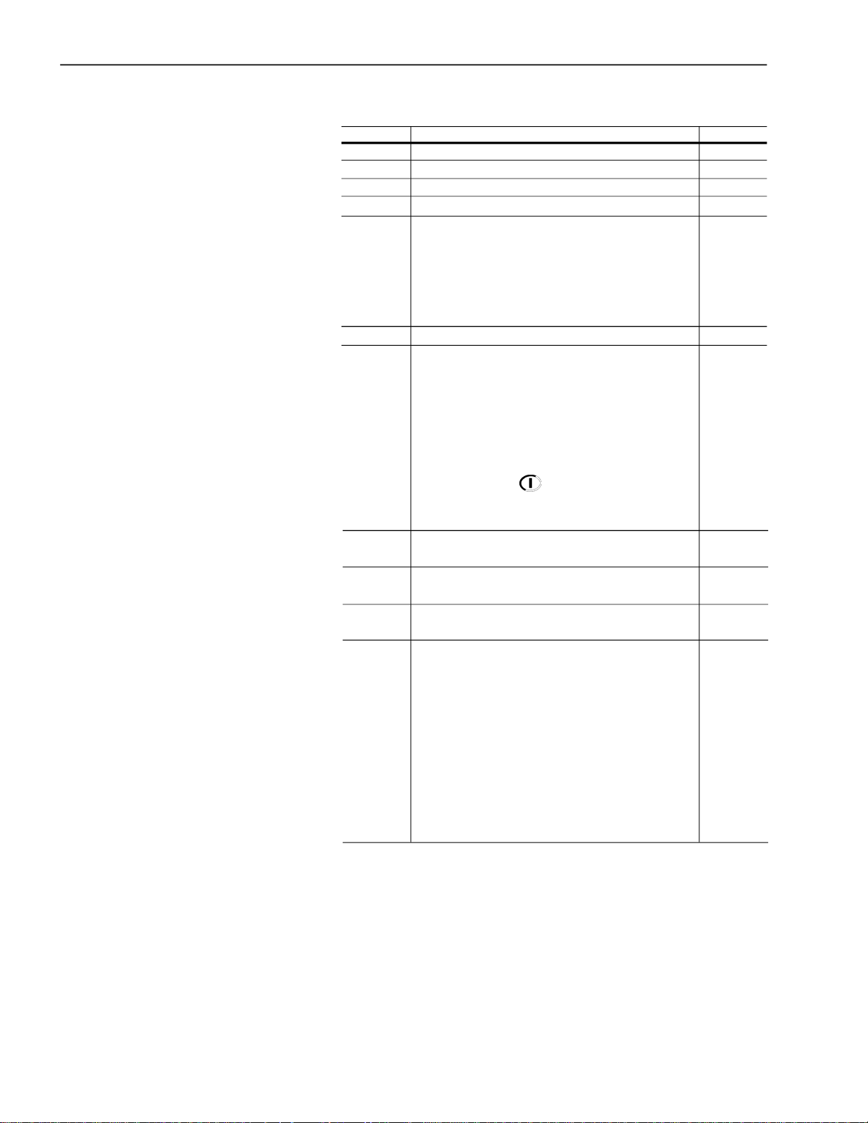
Summary of Revisions
The tablebelowdescribes the revisions made to this manual.
Revision Description Section
1 First edition 2 General revision 3 General revision 4 New software version 5 Implementation of the following current: 412A, Chap 3
480A, 604A, 670A, 820A, 950A, 1100A and 1400A. and 10
New software version with: braking methods 3, 4, 6
FWD/REVandJog. and 8
P140 was changed. E73 was eliminated.
E71 and E77 were changed.
6 General revision -
7 New software version with: new states in P006, Chap 4,
full voltage and starting diagnostic functions, 6 and 8
storage of the 6 last errors, consumed energy,
torque and power protections, motor thermal
protection alarm, selection between alarm or fault,
automatic detection of the acceleration end with
voltage ramp, fast visualization of the parameters
through the key, detection of the
Profibus DP master in Stop, and the PLC Software,
inclusion of the E11, E18, E57, E58 and E59.
8 Change of the table 3.1 and figures 10.1, 10.3, Chap 3 and
10.4, 10.5, 10.6 and 10.7. 10
9 Implementation of the following current: -
10A, 16A, 23A, 30A, 45A e 60A.
11 New line voltage of 690V for standard motor -
connection.
12 New software version with: digital inputs -
DI1, DI2 and DI3 programmable for the
same functions, new current models of
1000A and 1300A in P295, new option of
Fatal Fault for P313, disable of the E77 Fault
through the P621 for use in multimotor
applications, new MMC block for SoftPLC,
new P951 parameter for enable of the IOs
expansion card for SoftPLC, new
emergency start through digital input.
Newoptional kits KFB-DNIP, K-USB, K-IOE and K-ECA.

Summary
Quick Parameter Reference,
Fault and Status Messages
IParameters........................................................................................... 09
II FaultorAlarm Messages..................................................................... 20
III OtherMessages................................................................................. 20
CHAPTER 1
Safety Notices
1.1 Safety Notices in the Manual............................................................ 21
1.2 Safety Notices on the Product .......................................................... 21
1.3PreliminaryRecommendations ......................................................... 22
CHAPTER 2
General Information
2.1About this Manual............................................................................. 23
2.2SoftwareVersion............................................................................... 23
2.3Aboutthe Soft-StarterSSW-06 ......................................................... 23
2.4Soft-Starter SSW-06Identification .................................................... 27
2.5Receiving andStorage ...................................................................... 29
CHAPTER 3
Installation and Connection
3.1Mechanical Installation ..................................................................... 30
3.1.1EnvironmentConditions .............................................................. 30
3.1.2Dimensions of the Soft-Starter SSW-06...................................... 30
3.1.3 Positioning / Fixing..................................................................... 31
3.1.3.1 Mounting inside a Panel .................................................... 32
3.1.3.2Mounting on a Surface....................................................... 35
3.2 Electrical Installation......................................................................... 36
3.2.1Power Terminals.......................................................................... 37
3.2.2Locationofthe Power/Grounding,Control Connectionsand
Fan VoltageSelection................................................................. 42
3.2.3Recommended Power/GroundingCables.................................... 43
3.2.4Connectionof the Power Supplyto the Soft-Starter .................... 46
3.2.4.1 Power Supply Capacity ..................................................... 46
3.2.4.2RecommendedFuses ....................................................... 47
3.2.5Connectionof the SSW-06Soft-Startertothe motor................... 48
3.2.5.1 StandardThree-WireConnection (P150=0=Inactive).......... 48
3.2.5.2InsideDeltaMotor Connection(P150=1=Active) ............... 49
3.2.6Grounding Connections .............................................................. 50
3.2.7Fan Connections ........................................................................ 51
3.2.8Signaland Control Connections.................................................. 52
3.2.9RS-232,X2SerialCommunicationConnection ........................... 55
3.2.10XC8SerialCommunication Board Connection .......................... 55
3.2.11XC6FieldbusCommunicationBoardConnection ...................... 55

Summary
3.3RecommendedSet-Ups.................................................................... 55
3.3.1RecommendedSet-upsusingKeypadCommand
with Isolating Contactor.............................................................. 57
3.3.2RecommendedSet-upsusingKeypadCommand
withCircuit-breaker .................................................................... 57
3.3.3Recommended Set-ups withCommandviaTwo-wire
Digital Inputs .............................................................................. 58
3.3.4RecommendedSet-upswith CommandviaThree-wire
Digital Inputs .............................................................................. 58
3.3.5RecommendedSet-upswith CommandviaThree-wire
Digital Input and Inside Delta Motor Connection. ........................ 59
3.3.6RecommendedSet-upswith CommandviaThree-wire
Digital Input or Serial Communication. ....................................... 59
3.3.7RecommendedSet-upswith CommandviaThree-wire
Digital Input or Fieldbus Communication. ................................... 60
3.3.8Recommended Setup withCommand viaDigitalInputs
and direction of rotation............................................................. 60
3.3.9Recommended Setup withCommand viaDigitalInputs
andReverse Braking .................................................................. 61
3.3.10RecommendedSetupwithCommand via Digital Inputs
and Optimal Braking ................................................................ 61
3.3.11 RecommendedSetupwithCommand via Digital Inputs
and DC-Braking......................................................................... 62
3.3.12RecommendedSetupwithCommand via Digital Inputs
and External By-pass Contactor .............................................. 62
3.3.13 Symbols ................................................................................... 63
3.4 EuropeanDirectivesfor ElectromagneticCompatibility
Requirements for Installation ........................................................... 64
3.4.1Installation .................................................................................. 64
CHAPTER 4
Keypad Operation
4.1Descriptionof the Keypad(HMI-SSW-06)......................................... 65
4.2 Use of the Keypad ............................................................................ 67
4.2.1Keypadusefor Soft-Starter SSW-06Operation .......................... 67
4.2.2 Keypad Display - SignallingIndications ...................................... 68
4.2.3Parameterviewing and programming .......................................... 69
CHAPTER 5
Start-up
5.1Power-up Preparation ....................................................................... 71
5.2InitialPower-up (requiredparametersettings) ................................... 72
5.3Start-up .............................................................................................79
5.3.1Start-up:OperationviaKeypadType of Control: VoltageRamp... 79

Summary
CHAPTER6
Detailed Parameter Description
6.1Access and Read Only Parameters - P000 to P099 ......................... 82
6.2 Regulation Parameters - P100 to P199............................................. 92
6.3ConfigurationParameters - P200 to P299......................................... 101
6.4 Serial Communication Parameters - P300 to P399........................... 114
6.5 Motor Parameters - P400 to P499 .................................................... 116
6.6 Special Function Parameters - P500 to P599 ................................... 117
6.7 Protection Parameters - P600 to P699 ............................................. 123
6.8 Selection Between Fault andAlarm - P700 to P790 ......................... 132
6.9 SoftPLC Parameters - P950 to P999 ................................................ 134
CHAPTER7
Programming Information and Suggestions
7.1Applicationsand Programming ......................................................... 135
7.1.1StartingbyVoltageRamp (P202=0)............................................ 137
7.1.2 Startingby Current Limit (P202=1).............................................. 138
7.1.3StartingbyCurrentRamp withHigh Initial Current(P202=4)....... 139
7.1.4StartingbyCurrentRamp withLow Initial Current(P202=4)........ 140
7.1.5StartingwithPump Control(P202=2).......................................... 141
7.1.6Starting with TorqueControl(P202=3)......................................... 143
7.1.6.1Loads with ConstantTorque (P202=3and P120=1 point) ... 144
7.1.6.2Loadswith Higher InitialTorque
(P202=3 and P120=3 points) ............................................. 144
7.1.6.3Loadswith ConstantTorque andS SpeedCurve
(P202=3 and 120=3 points)................................................145
7.1.6.4LoadswithQuadraticTorque and SSpeedCurve
(P202=3 and P120=2 points) .............................................. 145
7.1.6.5LoadswithQuadratic TorqueandLinearSpeedCurve
(P202=3 and P120=3 points) ............................................. 146
7.1.6.6LoadswithQuadraticTorque and Higher InitialTorque
(P202=3 and P120=3 points) .............................................. 146
7.1.6.7HydraulicPump Load Type(P202=3) ................................. 147
7.2ProtectionsandProgramming .......................................................... 150
7.2.1ThermalClasses......................................................................... 150
7.2.1.1 Suggestions on How to Set Thermal Class ........................ 150
7.2.1.2 Example on How to Set the Thermal Class ........................ 151
7.2.1.3TimeReductionWhenChangingfrom ColdStartingto
Hot Starting........................................................................ 152
7.2.1.4ServiceFactor .................................................................... 152
7.2.2Under-andOver-Protections...................................................... 153
7.2.2.1UndervoltageandOvervoltageprotection ............................ 153
7.2.2.2Underload Protection .......................................................... 153
7.2.2.3OverloadProtection ............................................................ 153

Summary
CHAPTER8
Diagnostics and Troubleshooting
8.1 Faults and Possible Causes ............................................................. 155
8.2Troubleshooting ................................................................................ 160
8.3 TechnicalAssistanceContacting ...................................................... 160
8.4PreventiveMaintenance .................................................................... 161
8.4.1CleaningInstructions .................................................................. 162
8.5 SparePart List.................................................................................. 163
CHAPTER 9
Options and Accessories
9.1Remote KeypadandCables ............................................................. 165
9.2RS-485for theSoft-Starter SSW-06 ................................................. 167
9.2.1RS-485CommunicationKit(KRS-485) ....................................... 167
9.2.2OptionalModuleMIW-02 ............................................................ 168
9.3 Fieldbus Communication Kits ........................................................... 168
9.3.1 FieldbusDeviceNetCommunicationKit (KFB-DN) ................... 168
9.3.2 Fieldbus Profibus DP CommunicationKit (KFB-DP) ................ 169
9.3.3 Fieldbus Profibus DP-V1CommunicationKit(KFB-PDPV1) ..... 169
9.3.4 FieldbusDeviceNet DriveProfileCommunication Kit (KFB-DD). 169
9.3.5 Fieldbus EtherNet/IP Communication Kit (KFB-ENIP).............. 170
9.4 USB.................................................................................................. 170
9.4.1 USB Communication Kit (K-USB) .............................................. 170
9.5 DigitalInputs and Outputs Expansion Card ..................................... 170
9.5.1 Digital Inputs and Outputs Expansion Kit (K-IOE)...................... 171
9.6 External CurrentAcquisition ............................................................. 171
9.6.1 External Current Acquisition Kit (K-ECA) ................................... 171
CHAPTER10
Technical Specifications
10.1Currents and RatingsAccording to UL508 ...................................... 173
10.2 Currents and Ratings for IP55, IV PoleWeg Motor......................... 175
10.3 PowerData..................................................................................... 177
10.4 Electronics/Programming Data....................................................... 177
10.5 MechanicalData............................................................................. 179
SSW-06- QUICK PARAMETERREFERENCE
QUICK PARAMETER REFERENCE, FAULT AND STATUS MESSAGES
Software:V1.6X
Application:
Model:
SerialNumber:
PersonResponsible:
Date: / / .
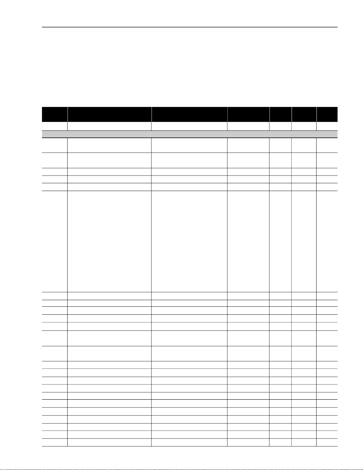
I.Parameters
Parameter Description Adjustable Range
P000 Parameter Access 0 to 999 0 - 82
READONLY PARAMETERS P001 to P099
P001 Soft-Starter Current 0 to 999.9 - % 83
(%In of the Soft-Starter)
P002 Motor Current 0 to 999.9 - % 83
(%In of the Motor)
P003 Motor Current 0 to 9999.9 - A 83
P004 Line Voltage 0 to 999 - V 83
P005 Line Frequency 0 to 99.9 - Hz 83
P006 Soft-Starter Status 0=Ready - - 84
1=InitialTest
2=Error
3=Ramp Up
4=FullVoltage
5=By-pass
6=Reserved
7=Ramp Down
8=Braking
9=FWD/REV
10=JOG
11=Delay P630
12=GeneralDisable
P007 Output Voltage 0 to 999 - V 84
P008 Power Factor 0 to 1.00 - - 84
P009 Motor Torque (% Tn of the Motor) 0 to 999.9 - % 84
P010 Output Power 0 to 6553.5 - kW 85
P011 Apparent Output Power 0 to 6553.5 - kVA 85
P012 Dl1toDI6Status 0=Inactive - - 85
1=Active
P013 RL1, RL2 and RL3 Status 0=Inactive - - 86
1=Active
P014 Last Fault 0 to 99 - - 86
P015 Second Previous Fault 0 to 99 - - 86
P016 Third Previous Fault 0 to 99 - - 86
P017 Fourth Previous Fault 0 to 99 - - 86
P018 Fifth Fault 0 to 99 - - 86
P019 Sixth Fault 0 to 99 - - 86
P020 Current Fault 0 to 99 - - 87
P021 CurrentAlarm 0 to 99 - - 87
P023 Software Version X.XX - - 87
P027 AO1 Output Value 0 to 10.000 - V 87
P028 AO2 Output Value 0 to 20.000 or 4.000 to 20.000 - mA 87
Factory
Setting Setting
Unit
User´s
Page
9

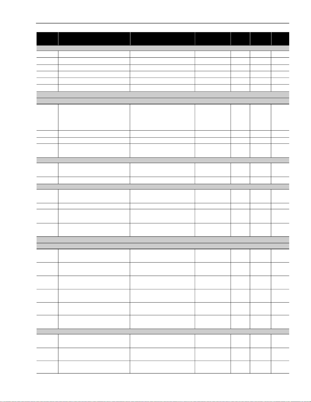
SSW-06- QUICK PARAMETER REFERENCE
Parameter Description Adjustable Range
P030 Current of Phase R 0 to 9999.9 - A 87
P031 Current of Phase S 0 to 9999.9 - A 87
P032 Current of Phase T 0 to 9999.9 - A 87
P033 Line Voltage - R-S 0 to 999 - V 87
P034 Line Voltage - S-T 0 to 999 - V 87
P035 Line Voltage - T-R 0 to 999 - V 87
P042 Time Powered 0 to 65535 - h 88
P043 TimeEnabled 0 to 6553,5 - h 88
P044 kWh Counter 0 to 999.9 - kWh 88
P045 MWhCounter 0 to 9999 - MWh 88
P047 MaximumStartingCurrent 0 to 9999.9 - A 88
P048 Average Starting Current 0 to 9999.9 - A 88
P049 RealStartingTime 0 to 999 - s 88
P050 MotorThermal Protection Status 0 to 250 - % 89
P053 MaximumCurrentat Full Voltage 0 to 9999.9 - A 89
P054 Maximum Line Voltage with the 0 to 999 - V 89
MotorRunning
P055 Minimum Line Voltage with the 0 to 999 - V 89
MotorRunning
P056 Maximum Line Frequency with the 0 to 99 - Hz 89
MotorRunning
P057 Minimum Line Frequency with the 0 to 99 - Hz 90
MotorRunning
P058 Maximum Number of Starts per Hour 0 to 32 - - 90
P059 Total Number of Starts 0 to 65535 - - 90
P060 Current at the Last Fault 0 to 9999.9 - A 90
P061 Voltage at the Last Fault 0 to 999 - V 90
P062 SSW Statusat the Last Fault 0 to 12 - - 90
P063 Current at the Second Fault 0 to 9999.9 - A 90
P064 Voltage at the Second Fault 0 to 999 - V 90
P065 SSW Statusat the Second Fault 0 to 12 - - 90
P066 Current at the Third Fault 0 to 9999.9 - A 90
P067 Voltage at the Third Fault 0 to 999 - V 90
P068 SSW Status at the Third Fault 0 to 12 - - 90
P069 Current at the Fourth Fault 0 to 9999.9 - A 90
P070 Voltage at the Fourth Fault 0 to 999 - V 90
P071 SSW Status at the Fourth Fault 0 to 12 - - 90
P072 Current at the Fifth Fault 0 to 9999.9 - A 90
P073 Voltage at the Fifth Fault 0 to 999 - V 90
P074 SSW Status at the Fifth Fault 0 to 12 - - 90
P075 Current at the Sixth Fault 0 to 9999.9 - A 90
P076 Voltage at the Sixth Fault 0 to 999 - V 90
P077 SSW Status at the Sixth Fault 0 to 12 - - 90
P085 Fieldbus Communication 0=Off - - 91
Board Status 1=Board Inactive
2=Board Active and Offline
3=Board Active and Online
P088 SoftPLCStatus 0=Without - - 91
1=Loading
2=Fault
3=Stopped
4=Running
Factory
Setting Setting
Unit
User´s
Page
10

SSW-06- QUICK PARAMETERREFERENCE
Parameter Description Adjustable Range
Factory
Setting Setting
Unit
User´s
Page
P089 Allows SoftPLC 0=No - - 91
1=Yes
REGULATION PARAMETERS P100 to P199
Voltage Ramp
P101 InitialVoltage 25 to 90 30 % 92
(% Un of the motor)
P102 AccelerationRampTime 1 to 999 20 s 92
P103 Deceleration Voltage Step 100=Inactive 100=Inactive % 93
(% Un of the motor) 99 to 60
P104 DecelerationRampTime 0=Inactive 0=Inactive s 93
1 to 299
P105 End Deceleration Voltage 30 to 55 30 % 94
(% Un of the Motor)
(1)
P106
Automatic Detection of the 0=ByTime 0=ByTime - 94
Acceleration End with Voltage Ramp 1=Automatic
Current Limit
P110 CurrentLimit 150 to 500 300 % 94
(%In of the Motor)
P111 Initial Current for the Current Ramp 150 to 500 150 % 95
(% In of the Motor)
P112 Time for the Current Ramp 1 to 99 20 % 95
(% of P102)
Torque Control
(1)
P120
Starting Torque Characteristics 1=Constant 1=Constant - 96
2=Linear
3=Quadratic
P121 InitialStarting Torque 10 to 400 30 % 97
(% Tn of Motor)
P122 End StartingTorque 10 to 400 110 % 97
(% Tn of Motor)
P123 MinimumStartingTorque 10 to 400 27 % 97
(% Tn of the Motor)
P124 TimefortheMinimum StartTorque 1 to 99 20 % 97
(% of P102)
(1)
P125
Stopping Torque Characteristics 1=Constant 1=Constant - 98
2=Linear
3=Quadratic
P126 End StopTorque 10 to 100 20 % 98
(% Tn of the Motor)
P127 MinimumStopTorque 10 to 100 50 % 99
(% Tn of the Motor)
P128 TimefortheMinimumStopTorque 1 to 99 50 % 99
(% of P104)
Pump Control
(1)
P130
PumpControl 0=PumpI 0=PumpI - 99
By-pass
(1)
P140
External By-pass Contactor 0=Inactive 0=Inactive - 99
1=Active
11

SSW-06- QUICK PARAMETER REFERENCE
Parameter Description Adjustable Range
Factory
Setting Setting
Unit
User´s
Page
Inside Delta
(1)(2)
P150
Inside Delta Motor Connection 0=Inactive 0=Inactive - 100
1=Active
CONFIGURATIONPARAMETERS P200 to P399
P200 Password 0=Inactive 1=Active - 101
1=Active
(2)
P201
Language Selection 0=Português To be defined - 101
1=English by the user
2=Español
3=Deutsch
(1)
P202
Type of Control 0=Voltage Ramp 0=VoltageRamp - 101
1=CurrentLimit
2=PumpControl
3=Torque Control
4=CurrentRamp
(1)
P204
Load/Save Parameters 0=NotUsed 0=NotUsed - 104
1=NotUsed
2=NotUsed
3=Resets P043 to P050
4=Resets P053 to P058
5=Loads Factory Default
6=NotUsed
7=Loads User Default 1
8=Loads User Default 2
9=NotUsed
10=Saves User Default 1
11=Saves User Default 2
12= Not Used
13=Erases SoftPLC
14=Erases SoftPLC User
Parameters
15=Reserved
16=Reserved
P205 Display Default Selection 0=P001 2=P003 - 105
1=P002
2=P003
3=P004
4=P005
5=P006
6=P007
7=P008
8=P009
9=P010
P206 Auto-Reset Time 0=Inactive 0=Inactive s 105
1 to 600
(1)
P215
Copy Function 0=Inactive 0=Inactive - 106
1=SSW HMI
2=HMISSW
P218 LCD Display Contrast Adjust. 0 to 150 127 - 107
12

SSW-06- QUICK PARAMETERREFERENCE
Parameter Description Adjustable Range
Factory
Setting Setting
Unit
User´s
Page
Local/Remote Definition
(1)
P220
Local/Remote Source Selection 0=Always Local 2=Keypad (L) - 107
1=Always Remote
2=Keypad (L)
3=Keypad (R)
4=DI4toDI6
5=Serial (L)
6=Serial (R)
7=Fieldbus (L)
8=Fieldbus (R)
9=SoftPLC(L)
10=SoftPLC(R)
(1)
P229
LocalStatusCommandSelection 0=HMIKey 0=HMIKey - 108
1=DigitalInputs DIx
2=Serial
3=Fieldbus
4=SoftPLC
(1)
P230
RemoteStatus CommandSelection 0=HMIKey 1=Digital InputsDIx - 108
1=DigitalInputs DIx
2=Serial
3=Fieldbus
4=SoftPLC
(1)
P231
FWD/REVSelection 0=Inactive 0=Inactive - 108
1=By Contactor
2=JOGOnly
Analog Outputs
P251 AO1 (0 to 10)V Output Function 0=NotUsed 0=Not Used - 109
1= Current
(%In of the SSW)
2=Input Voltage
(%Un of the SSW)
3=Output Voltage
(%Un of the SSW)
4=Power Factor
5=ThermalProtection
6=Power (in W)
7=Power (in VA)
8=Torque
(%Tn of Motor)
9=Fieldbus
10=Serial
11=SoftPLC
P252 AO1 Analog Output Gain 0.000 to 9.999 1.000 - 109
P253 AO2 (0 to 20)mA or (4 to 20)mA 0=NotUsed 0=Not Used - 109
Output Function 1= Current
(%In of the SSW)
2=Input Voltage
(%Un of the SSW)
3=Output Voltage
(%Un of the SSW)
4=Power Factor
13

SSW-06- QUICK PARAMETER REFERENCE
Parameter Description Adjustable Range
Factory
Setting Setting
Unit
User´s
Page
5=ThermalProtection
6=Power (in W)
7=Power (in VA)
8=Torque
(%Tn of the Motor)
9=Fieldbus
10=Serial
11=SoftPLC
P254 AO2 Analog Output Gain 0.000 to 9.999 1.000 - 109
P255 AO2 Analog Output Selection 0=0 to 20 0=0 to 20 mA 110
1=4 to 20
Digital Inputs
(1)
P263
Digital Input DI1 Function 0=Not Used 1=Start/Stop 111
1=Start/Stop
2=Start (Three Wires)
3=Stop (Three Wires)
4=General Enabling
5=Reset
(1)
P264
Digital Input DI2 Function 0=Not Used 2=Reset 111
1=Stop (Three-Wires)
2=Reset
3=Start/Stop
4=Start (Three Wires)
5=General Enabling
(1)
P265
Digital Input DI3 Function 0=Not Used 0=Not Used 111
1=General Enabling
2=Reset
3=Start/Stop
4=Start (Three Wires)
5=Stop (Three Wires)
6=Emergency Start
(1)
P266
DI4Digital InputFunction 0=Not Used 0=Not Used - 111
1=FWD/REV
2=Local/Remote
3=NoExternalFault
4=JOG
5=Brake Off
6=Reset
(1)
P267
DI5Digital InputFunction 0=Not Used 0=Not Used - 111
1=FWD/REV
2=Local/Remote
3=NoExternalFault
4=JOG
5=Brake Off
6=Reset
(1)
P268
DI6Digital InputFunction 0=Not Used 0=Not Used - 111
1=FWD/REV
2=Local/Remote
3=NoExternalFault
4=JOG
5=Brake Off
6=Reset
7=MotorThermistor
14

SSW-06- QUICK PARAMETERREFERENCE
Parameter Description Adjustable Range
Digital Outputs
(1)
P277
RL1 Relay Function 0=Not Used 1=Running - 112
1=Running
2=FullVoltage
3=External By-pass
4=FWD/REV-K1
5=DC-Brake
6=NoFault
7=Fault
8=Fieldbus
9=Serial
10=SoftPLC
11=NoAlarm
12=Alarm
(1)
P278
RL2 Relay Function 0=NotUsed 2=FullVoltage - 112
1=Running
2=FullVoltage
3=External By-pass
4=FWD/REV-K2
5=DC-Brake
6=NoFault
7=Fault
8=Fieldbus
9=Serial
10=SoftPLC
11=NoAlarm
12=Alarm
(1)
P279
RL3 Relay Function 0=NotUsed 6=NoFault - 112
1=Running
2=FullVoltage
3=External By-pass
4= Not Used
5=DC-Brake
6=NoFault
7=Fault
8=Fieldbus
9=Serial
10=SoftPLC
11=NoAlarm
12=Alarm
Soft-Starter Data
(1)(2)
P295
SSW NominalCurrent 0=10 11=312 According to A 113
1=16 12=365 Soft-Starter
2=23 13=412 Nominal Current
3=30 14=480
4=45 15=604
5=60 16=670
6=85 17=820
7=130 18=950
8=170 19=1100
9=205 20=1400
10=255 21=1000
22=1300
Factory
Setting Setting
Unit
User´s
Page
15

SSW-06- QUICK PARAMETER REFERENCE
Parameter Description Adjustable Range
(1)(2)
P296
SSW NominalVoltage 0=220/575 According to V 114
Factory
Setting Setting
Unit
User´s
Page
1=575/690 Soft-StarterNominal
Voltage
SERIAL COMMUNICATION PARAMETERS P300 to P399
(1)(2)
P308
Soft-Starter Address on the Serial 1 to 247 1 - 114
Communication Network
(1)(2)
P309
Fieldbus Communication 0=Inactive 0=Inactive - 114
BoardEnabling 1=Profibus-DP
(1 Input and 1 Output)
2=Profibus-DP
(4 Inputs and 4 Outputs)
3=Profibus-DP
(7 Inputs and 7 Outputs)
4=DeviceNet
(1 Input and 1 Output)
5=DeviceNet
(4 Inputs and 4 Outputs)
6=DeviceNet
(7 Inputs and 7 Outputs)
7=EtherNet/IP
(1 Input and 1 Output)
8=EtherNet/IP
(4 Input and 4 Output)
9=EtherNet/IP
(7 Input and 7 Output)
P310 Profibus Master Stop Detection 0=Inactive 0=Inactive - 114
1=Active
(1)(2)
P312
Protocol Type and Serial 1=Modbus-RTU 1=Modbus-RTU - 115
Communication Transfer Rate (9600bps, no parity) (9600bps,
2=Modbus-RTU no parity)
(9600bps, odd)
3=Modbus-RTU
(9600bps, even)
4=Modbus-RTU
(19200bps, no parity)
5=Modbus-RTU
(19200bps, odd)
6=Modbus-RTU
(19200bps, even)
7=Modbus-RTU
(38400bps, no parity)
8=Modbus-RTU
(38400bps, odd)
9=Modbus-RTU
(38400bps, even)
P313 Serialand Fieldbus Communication 0=Inactive 0=Inactive - 115
ErrorActions (E28, E29 and E30) 1=Disable
2=GeneralDisable
3=Changes to Local
4=Inactive
5=FatalFault
(1)
P314
TimeoutTime forSerial 0 to 999 0=Not Used s 115
CommunicationTelegram Reception
(1)
P315
P316
P317
Read Parameter via Fieldbus 1 0 to 999 0 - 115
(1)
Read Parameter via Fieldbus 2 0 to 999 0 - 116
(1)
Read Parameter via Fieldbus 3 0 to 999 0 - 116
16
SSW-06- QUICK PARAMETERREFERENCE
Parameter Description Adjustable Range
Factory
Setting Setting
Unit
User´s
Page
MOTOR PARAMETERS P400 to P499
(1)
P400
P401
P402
P404
P405
P406
NominalMotorVoltage 0 to 999 380 V 116
(1)
NominalMotorCurrent 0 to 2424 20 A 116
(1)
NominalMotorSpeed 400 to 3600 1780 rpm 116
(1)
Nominal Motor Power 0.1 to 2650 75 kW 116
(1)
Motor Power Factor 0 to 1.00 0.89 - 116
(1)
Service Factor 0 to 1.50 1.00 - 117
SPECIALFUNCTIONPARAMETERS P500 to P599
Braking
(1)
P500
Braking Methods 0=Inactive 0=Inactive - 117
1=Reverse Braking
2=OptimalBraking
3=DC-Braking
P501 BrakingTime 1 to 299 10 s 120
P502 Braking Voltage Level 30 to 70 30 % 120
P503 BrakingEndDetection 0=Inactive 0=Inactive - 120
1=Automatic
JOG
(1)
P510
Jog 0=Inactive 0=Inactive - 121
1=Active
P511 Jog Level 10 to 100 30 % 121
Kick Start
(1)
P520
Kick Start Torque Pulse 0=Inactive 0=Inactive - 122
(according to P202) 1=Active
P521 KickStartPulse Time 0.1 to 2 0.1 s 122
P522 Kick StartVoltage Pulse Level 70 to 90 70 % 122
(% Un of the Motor)
P523 Kick StartCurrent Pulse Level 300 to 700 500 % 122
(% In of the Motor)
PROTECTION PARAMETERS P600 to P699
Voltage Protection
(1)
P600
ImmediateUndervoltage 0 to 30 20 % 123
(% Un of the Motor)
(1)
P601
ImmediateUndervoltageTime 0=Inactive 1 s 123
1 to 99
(1)
P602
ImmediateOvervoltage 0 to 30 15 % 123
(% Un of the Motor)
(1)
P603
ImmediateOvervoltageTime 0=Inactive 1 s 123
1 to 99
(1)
P604
Voltage Imbalance between Phases 0 to 30 15 % 123
(% Un of the Motor)
(1)
P605
Voltage Imbalance between 0=Inactive 1 s 123
PhasesTime 1 to 99
Current Protection
(1)
P610
Immediate Undercurrent 0 to 99 20 % 124
(% In of the Motor)
(1)
P611
ImmediateUndercurrentTime 0=Inactive 0=Inactive s 124
1 to 99
(1)
P612
Immediate Overcurrent 0 to 99 20 % 124
(% In of the Motor)
17

SSW-06- QUICK PARAMETER REFERENCE
Parameter Description Adjustable Range
(1)
P613
ImmediateOvercurrent Time 0=Inactive 0=Inactive s 124
Factory
Setting Setting
Unit
User´s
Page
1 to 99
(1)
P614
Current Imbalance between Phases 0 to 30 15 % 124
(% In of the Motor)
(1)
P615
Current Imbalance between 0=Inactive 1 s 124
PhasesTime 1 to 99
(1)
P616
Undercurrent before 0=Inactive 1=Active - 125
By-pass Closing 1=Active
(1)
P617
Locked Rotor at the 0=Inactive 1=Active - 125
StartEnd 1=Active
(1)
P618
P619
Ground Fault 10 to 30 20 % 125
(1)
GroundFault Time 0 to 10.0 0=Inactive s 125
Phase Sequence
(1)
P620
RST Phase Sequence 0=Inactive 0=Inactive - 125
1=Active
By-pass Contactor Closed Detection
(1)
P621
By-pass Contactor Closed 0=Inactive 1=Active 125
1=Active
Interval between Starts
P630 Interval of Time after Stop 2 to 999 2 s 125
Motor Thermal Protection
(1)
P640
MotorProtection Thermal Class 0=Inactive 5=25 6=30 - 127
1=5 6=30
2=10 7=35
3=15 8=40
4=20 9=45
(1)
P641
Auto-Reset of the Thermal Memory 0=Inactive 0=Inactive s 130
1 to 600
P642 MotorThermal ProtectionAlarm 0 to 250 230 % 131
P643 MotorThermal ProtectionAlarm Reset 0 to 250 210 % 131
Torque Protections
(1)
P650
ImmediateUndertorque 0 to 99 30 % 131
(% Tn of the Motor)
(1)
P651
P652
ImmediateUndertorque Time 0 to 99 0=Inactive s 131
(1)
ImmediateOvertorque 0 to 99 30 % 131
(% Tn of the Motor)
(1)
P653
ImmediateOvertorqueTime 0 to 99 0=Inactive s 131
Power Protections
(1)
P660
Immediate Underpower 0 to 99 30 % 132
(% kWn of the Motor)
(1)
P661
P662
Immediate Underpower Time 0 to 99 0=Inactive s 132
(1)
Immediate Overpower 0 to 99 30 % 132
(% kWn of the Motor)
(1)
P663
Immediate Overpower Time 0 to 99 0=Inactive s 132
SELECTION BETWEEN FAULT OR ALARM P700 to P790
P705 MotorThermalProtectionTrip 0=FaultE05 0=FaultE05 - 132
1=Alarm A05
2=Fault andAlarm
P706 OpenDIxProtection Trip 0=Fault E06 0=FaultE06 - 133
1=Alarm A06
P716 Line Overvoltage Trip 0=FaultE16 0=Fault E16 - 133
1=Alarm A16
18

SSW-06- QUICK PARAMETERREFERENCE
Parameter Description Adjustable Range
P732 Motor Overtemperature – PTC – Trip 0=Fault E32 0=FaultE32 - 133
1=Alarm A32
P765 Motor Undercurrent Trip 0=FaultE65 0=FaultE65 - 133
1=Alarm A65
P766 Motor Overcurrent Trip 0=Fault E66 0=FaultE66 - 133
1=Alarm A66
P778 Motor Undertorque Trip 0=FaultE78 0=FaultE78 - 133
1=Alarm A78
P779 Motor Overtorque Trip 0=FaultE79 0=FaultE79 - 133
1=Alarm A79
P780 Motor Underpower Trip 0=Fault E80 0=FaultE80 - 133
1=Alarm A80
P781 Motor Overpower Trip 0=FaultE81 0=Fault E81 - 133
1=Alarm A81
SOFTPLCPARAMETERS P950 to P999
Control Parameters
(2)
P950
P951 Digital Inputs and Outputs Expansion 0=No 0=No 134
P952 First SoftPLC User Parameter 0 to 65535 0 - 134
P953 Second SoftPLC User Parameter 0 to 65535 0 - 134
P954 ThirdSoftPLCUser Parameter 0 to 65535 0 - 134
P955 Fourth SoftPLC User Parameter 0 to 65535 0 - 134
P956 Fifth SoftPLC User Parameter 0 to 65535 0 - 134
P957 Sixth SoftPLC User Parameter 0 to 65535 0 - 134
P958 Seventh SoftPLC User Parameter 0 to 65535 0 - 134
P959 EighthSoftPLCUserParameter 0 to 65535 0 - 134
P960 NinthSoftPLCUserParameter 0 to 65535 0 - 134
P961 Tenth SoftPLC User Parameter 0 to 65535 0 - 134
P962 EleventhSoftPLCUserParameter 0 to 65535 0 - 134
P963 Twelfth SoftPLC User Parameter 0 to 65535 0 - 134
P964 ThirteenthSoftPLC User Parameter 0 to 65535 0 - 134
P965 Fourteenth SoftPLC User Parameter 0 to 65535 0 - 134
P966 Fifteenth SoftPLC User Parameter 0 to 65535 0 - 134
P967 Sixteenth SoftPLC User Parameter 0 to 65535 0 - 134
P968 Seventeenth SoftPLC User Parameter 0 to 65535 0 - 134
P969 EighteenthSoftPLCUserParameter 0 to 65535 0 - 134
EnableSoftPLC 0=No 0=No - 134
1=Yes
CardEnable 1=Yes
User Parameters
Factory
Setting Setting
Unit
User´s
Page
NotespresentedonQuick Parameter Reference:
(1) This parameter can onlybe changedwith the motor stopped;
(2)Thisparameterdoesnotchangewhenfactorydefaultsareloaded(P204=5).
19

SSW-06- QUICK PARAMETER REFERENCE
II.FaultorAlarmMessages
Display Description Page
E03 Undervoltage, Phase Fault or Phase 155
Unbalancing
E04 Overtemperature at the Power Assembly 155
E05 or A05 Motor Overload 155
E06 or A06 External Fault or Alarm (DI) 155
E10 Copy Function Fault 155
E11 Ground Fault 156
E15 Motor is not Connected or SCRs in Short-circuit 156
E16 or A16 Overvoltage 156
E18 Wrong Motor Connection 156
E24 ProgrammingError 156
E28 Timeout Errorin the Telegram Reception 156
E29 Inactive Fieldbus communication or Profibus 156
master in Stop Fault
E30 Fieldbus Board is Inactive 156
E31 Keypad Connection Fault 156
E32 or A32 Motor Overtemperature (DI) 157
E41 Self-Diagnosis Fault 157
E57 Failure inSCRR-U 157
E58 Failure in SCR S-V 157
E59 Failure inSCRT-W 157
E62 StartLimitingTime 157
E63 Locked Rotor 157
E65 or A65 Undercurrent 157
E66 or A66 Overcurrent 157
E67 Inverted Phase Sequence 157
E70 Undervoltage at the Electronics 157
E71 By-pass Contact is Open 158
E72 Overcurrent before By-pass Contact 158
E74 Current Imbalance 158
E75 Frequency of Supply Line out of Permitted Range 158
E76 Undercurrent before By-pass 158
E77 By-pass Contact is closed or SCRs in Short-circuit 158
E78 or A78 Undertorque 158
E79 or A79 Overtorque 158
E80 or A80 Underpower 158
E81 or A81 Overpower 158
E85 Without SoftPLC 159
E86 to E89 SoftPLC user errors 159
A90 to A93 SoftPLC user alarms 159
For more details see table 8.1 in chapter 8.
III.OtherMessages
20
Display Description
rdy Soft-Starter is ready to be enabled
Exx Soft-Starter fault
Axx Soft-Starter with alarm
CHAPTER 1
SAFETY NOTICES
ThisManualcontainsallnecessaryinformationforthecorrectinstallation
andoperationof the SSW-06 Soft-Starter.
TheSSW-06InstructionManualhasbeenwritten for qualifiedpersonnel
with suitable training or technical qualifications to operate this type of
equipment.
1.1 SAFETYNOTICES INTHEMANUAL
1.2 SAFETYNOTICESON THEPRODUCT
The following Safety Notices will be used in this Manual:
DANGER!
Iftherecommended SafetyInstructionsarenotstrictlyobserved,serious
orfatalinjuries ofpersonneland/or equipment damagecan occur.
ATTENTION!
Failure to observe the recommended Safety Procedures can lead to
materialdamage.
NOTE!
ThecontentofthisManualsupplies importantinformation for thecorrect
understandingof operationandproperperformanceof the equipment.
Thefollowingsymbolsmaybeattachedtotheproduct, servingas Safety
Notices:
High Voltages.
Componentsaresensitivetoelectrostaticdischarge.Do not touch
them without following proper grounding procedures.
Mandatory connection to ground protection (PE).
Shield connection to ground.
21
CHAPTER 1 - SAFETY NOTICES
1.3 PRELIMINARY RECOMMENDATIONS
DANGER!
Only qualified personnel should plan or implement the installation, start-up,
operationandmaintenanceofthisequipment.Personnelmustreviewthisentire
Manualbefore attemptingtoinstall,operate or troubleshoot the SSW-06.
These personnel must follow all safety instructions included in this Manual
and/ordefined by local regulations.
Failure to complywith these instructions mayresult in personal injuryand/or
equipment damage.
NOTE!
In this Manual,qualified personnel are defined as peoplethat aretrained to:
1. Install,ground, power-up and operate theSSW-06 accordingto this
Manual and the local requiredsafetyprocedures;
2. Use of safety equipment according to the local regulations;
3. Administer First Aid Treatment.
DANGER!
Always disconnect the main power supply before touching any electrical
component associated with the SSW-06 Soft-Starter.
High voltages and spinningparts (fans) may be present even after switching
offthepowersupply.Wait at least3minutesfor the completedischargeofthe
capacitors and until the fans stopped.
Always connect the equipment frame to the protection earth (PE) in the
appropriateplacefor this.
ATTENTION!
All electronic boards have components that are sensitive to electrostatic
discharges.Nevertouchanyoftheelectricalcomponentsor connectorswithout
followingproper groundingprocedures.Ifnecessarytodoso,touchtheproperly
groundedmetallic frame or use a suitableground strap.
Do not apply a high voltage (High Pot) test on the Soft-Starter SSW-06!
If this test is necessary, contact the manufacturer.
NOTE!
Soft-StarterSSW-06 can interfere withotherelectronicequipment.In orderto
reduce this interference, adopt the measures recommended in Section 3
“Installation”.
NOTE!
Readthisentire manualcarefullyandcompletelybeforeinstalling or operating
theSoft-Starter SSW-06.
22

CHAPTER 2
GENERAL INFORMATION
This chapter defines the contents and purpose of this manual and
describes the main characteristics of the SSW-06 Soft-Starter.
Identification of the SSW-06, receiving and storage requirements are
alsoprovided.
2.1 ABOUT THISMANUAL
This manual is divided into 10 chapters, providing information to the
user on how to receive, install, start-up and operate the Soft-Starter
SSW-06.
Chapter1- Safety Notices;
Chapter2- Generalinformation,receivingandstoringoftheSSW-06;
Chapter3- Informationaboutinstallationandconnectionof the
Soft-Starter SSW-06 power and control circuit, how to
installoptions and recommended setups;
Chapter4- Usingthe Keypad(Human Machine Interface - HMI);
Chapter5- Informationaboutrunningandsteps to befollowed;
Chapter6- Detaileddescription of all Soft-StarterSSW-06
programmingparameters;
Chapter7- Information and suggestions on how to program the
types of control and protections;
Chapter8- Informationaboutdiagnostics andtroubleshooting,
cleaninginstructionsandpreventive maintenance;
Chapter9- SSW-06Soft-Starter optionaldevices;
Chapter10- Tables and technical informationabout the powerlines
of the Soft-Starter SSW-06.
Thismanualprovidesinformationforthecorrectuse of theSoft-Starter
SSW-06.Duetothevariousfunctions oftheSoft-StarterSSW-06many
differentmodesof operationarepossible.
As the Soft-Starter SSW-06 can be applied in several ways, it is
impossible to describe here all application possibilities, neither can
WEG assume any responsibility when the Soft-Starter SSW-06 is not
used according to this manual.
No part of this manual maybe reproduced in any form, withoutwritten
permissionfrom WEG.
2.2 SOFTWARE VERSION
2.3 ABOUT THE SOFT-STARTER SSW-06
It is important to note the software version installed in the Soft-Starter
SSW-06,sinceitdefinesthefunctionsandtheprogrammingparameters
ofthe Soft-Starter.Thismanualrefersto the software versionindicated
on the inside cover. For example, the version 1.0X applies to versions
1.00 to1.09,where“X”isavariablethatwillchangeduetominorsoftware
revisions.
Thesoftwareversion can bereadin the parameterP023.
TheSoft-StarterSSW-06is a highperformance Drive that permits the
start control of three-phase AC induction motors. The Soft-Starter
SSW-06 prevents mechanical shocks on the load and current peaks
in the supply line.
Amongthemaincharacteristics of thisproduct is its lineandconnection
faultdetection capacity thus enablingthe customer to choose the best
wayof protecting his motor, such as:
23

CHAPTER2 - GENERALINFORMATION
Programmableprotectionsagainstlineundervoltageandovervoltage,
andline phase imbalance;
Programmable protections against motor undercurrent and
overcurrent,andcurrentimbalancebetweenphasesofthe motor;
ThermalclassmaybeprogrammeduptoClass45for largemotors.
Thethermal memoryissavedon EEPROMincaseof anelectronic
supply fault.
Specialfunctions such as:
Displayofthenumberof hours, runningtime,supplyvoltagephase,
motor current per phase, motor current in amperes, motor current
asa % of the Soft-StarterSSW-06nominalcurrentand the nominal
current as a % of the motor current, status of the digital inputs and
outputs;
Setting sequence after reset to factory default;
Veryflexibleselectionofstart/stopcontroltype,enablingthefollowing
selections: VoltageRamp, Constant Current Limiting or by Ramp,
PumpControland Constant,Linear or QuadraticTorqueControl;
Totally flexibleTorque Control providing very high performance for
themost demanding applications;
Possibility of using all digital inputs, digital outputs and analog
outputs as remote PLC via Serial and Fieldbus communication;
Possibilityofline voltagemeasurements monitoringbyasupervisory
implementedthroughSerialor Fieldbus communication;
Monitoring and programmingviasoftwareSuperDriveG2.
Indication of starting and full voltagediagnostics, and faults.
Control Hardware:
Keypad, referred to as the Human Machine Interface (HMI) with
Liquid-Crystal Displayandeasyprogramming.Faultconditionscan
bedisplayedinseverallanguages.
32Bit Microprocessor calculates the True rms voltageand current;
Measurement of the voltageand currentin the three phases;
Isolated digital input for the motor PTC;
Fieldbus boards and RS-485as options.
Power Hardware:
Compact size;
Power supply input and output connections:
Models from 10A to 820A - Input from the top and output at the
bottom of the SSW-06, with built-in By-pass contactor;
Models from 950A to 1400A - Input and output from the bottom,
without built-in By-pass contactor;
Easy assembly and maintenance;
Measurements of heatsink temperature in models 255A to 820A
through two thermostats:One thermostat to switch-on the internal
fansand the other to monitorover-heating;
Soft-Starter SSW-06 can be coupled to the motor by a standard
connection or an inside delta motor connection without requiring
optionaldevices.
Built-inBy-pass contactor makesthe Soft-StarterSSW- 06(Models
from 10Ato 820A):
More resistant to supply line oscillations after starting;
Save energy that would be dissipated through the thyristors after
thestart,thus reducingthenumber of fans requiredforcontrolpanel
cooling.
24
CHAPTER2 - GENERALINFORMATION
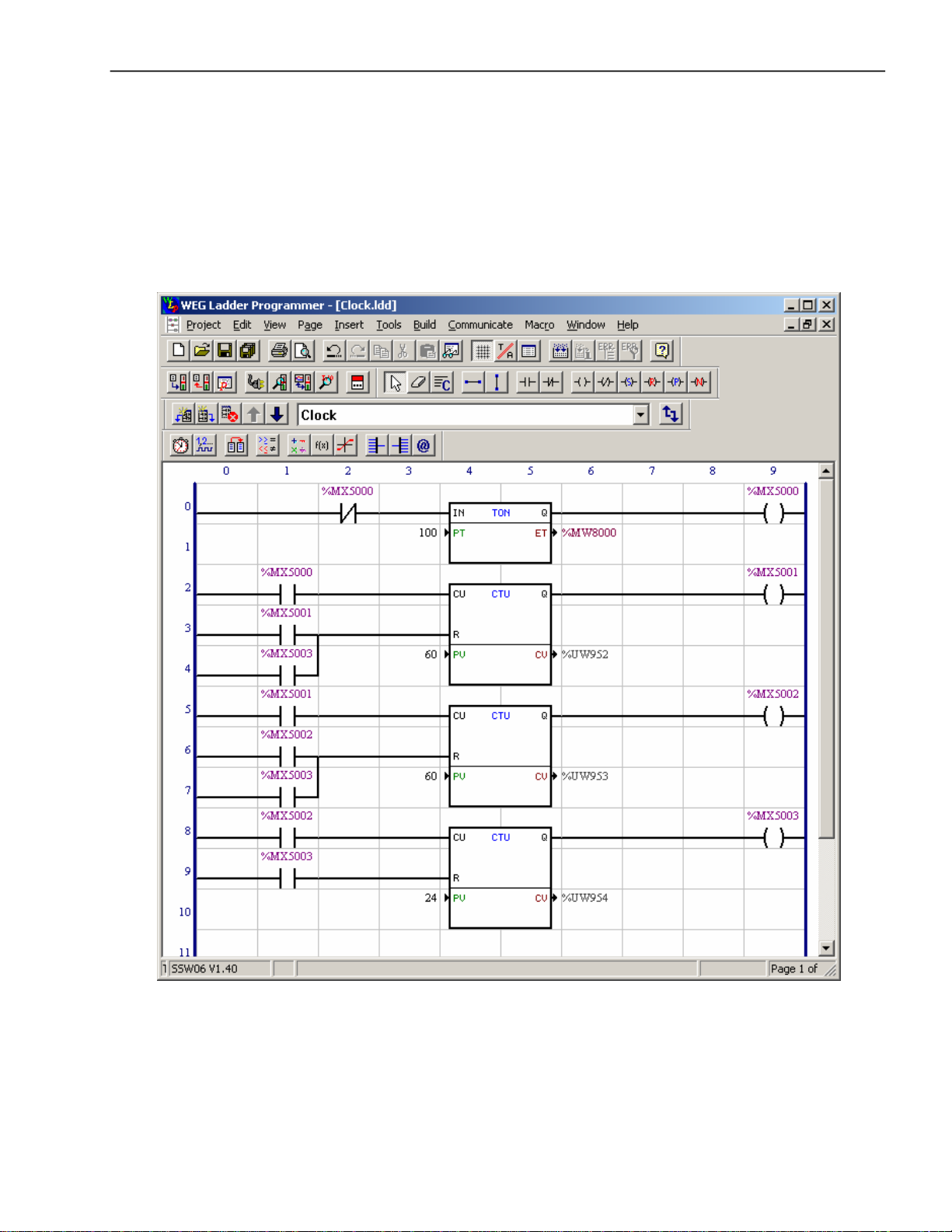
PLC Software Function - SoftPLC
TheSSW-06Soft-Starterallowstheimplementation ofprogrammable
logic controller software in ladder language, the SoftPLC, with an
applicativeprogram capacity of 1 Kbyte.
With the SoftPLC, interlocking logics between digital inputs and
outputs, analog outputs, motor starting logics, among others, can
becreated.
ThisSoftPLCisprogrammablethroughtheWLP software,according
to the WLP manual.
Figure 2.1 - Example of SoftPLC software with the WLP editing tool
Theexample aboveistheimplementationofaclock withhours,minutes
and seconds. The hours are showed in parameter P954, the minutes
inparameter P953 and the seconds in parameterP952.
25
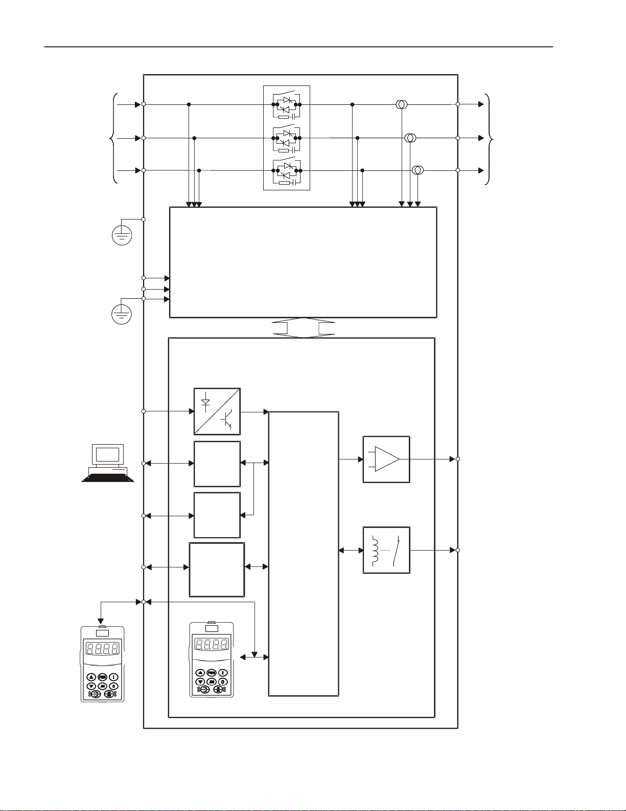
CHAPTER2 - GENERALINFORMATION
(1)
Three-Phase
Power Supply
Programmable
DigitalInputs
DI1to DI6
PE
Control
Supply
PE
Input Voltage
Supply
DigitalInputs
(1)
(1)
POWERBOARD
CONTROL BOARD
Output
Voltage
Analog Outputs
Three-Phase
Motor
Current
PC,PLC,MFW,
SuperDrive G2
ModBUS-RTU
PC,PLC
Keypad
(Remote)
Serial
Interface
CPU
RS-232
Serial
Interface
(optional)
DigitalOutputs
RS-485
Fieldbus
(optional)
- ProfibusDP
- DeviceNet
Keypad
(1) Models 950A, 1100A and 1400A do not have an internal By-pass contactor.
Programmable
Analog Outputs
AO1 to AO2
Programmable
DigitalOutputs
RL1 to RL3
26
Figure 2.2 - Soft-Starter SSW-06 block diagram
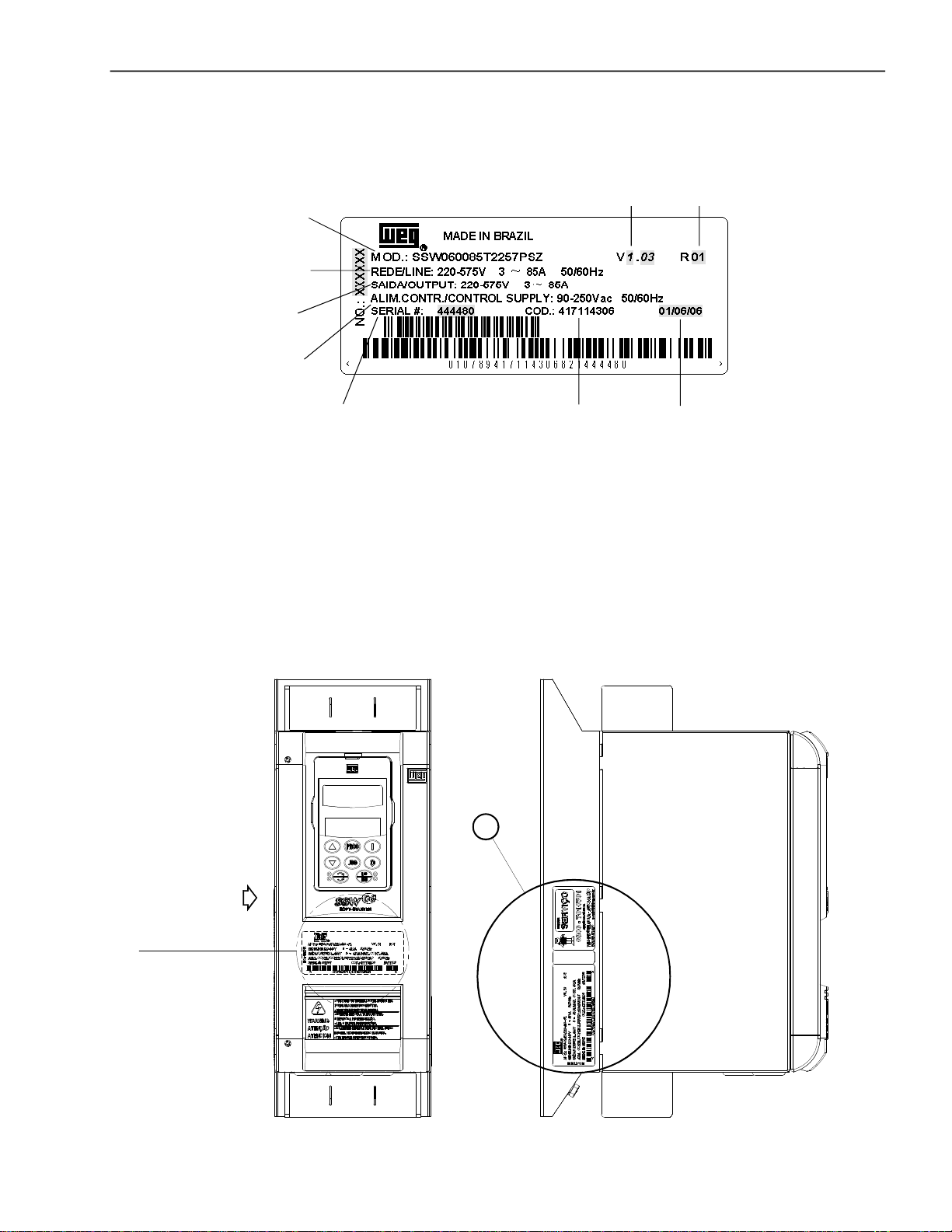
2.4 SOFT-STARTERSSW-06IDENTIFICATION
CHAPTER2 - GENERALINFORMATION
SSW-06 Model
Input Data (Voltage,Number of
Phases, Current, Frequency)
Output Data (Voltage, Number
of Phases, Current)
Control Power Supply Data
(Voltage, Frequency)
SerialNumber
Figure 2.3 - Soft-Starter SSW-06 nameplate
Software
Version
WEGItem
Number
Hardware
Revision
Manufacturing
Date
LocationofSoft-Starter SSW-06 nameplate:
X
VER DETALHE "A"
View Detail A
Identificationnameplate
of the SSW-06
(Internal Cover)
FRONT VIEW VIEW X
FRONTAL
VISTA DE X
A
Figure 2.4 - Detail of the Soft-Starter SSW-06 nameplate
27

CHAPTER2 - GENERALINFORMATION
End of
code
Special
software:
Blank =
standard
S1=special
software
Special
hardware:
Blank =
standard
H1 = 115V
ventilation
(model 950A)
H2 = 230V
ventilation
(models
950A,1100A
and1400A)
Human-
Machine
Interface
(Keypad):
Blank =
standard
SI= without
keypad
Options:
S=standard
O=with options
Manual
language:
P=portuguese
E=english
S=spanish
G=german
HOW TO SPECIFY THE SSW-06 MODEL:
Power supply
voltage:
2257=
(220 to 575)V
5769=
(575 to 690)V
Thee-phase
power supply
(1)
(1)
(1)
(1)
Nominal
output
current:
0010=10A
0016=16A
0023=23A
0030=30A
0045=45A
0060=60A
0085=85A
0130=130A
0170=170A
0205=205A
0255=255A
0312=312A
0365=365A
0412=412A
0480=480A
0604=604A
0670=670A
0820=820A
0950=950A
1100=1100A
1400=1400A
28
SSW-06 0085 T 2257 E S _ _ _ _ _ _ Z
Soft-Starter
SSW-06
WEG Series
NOTE!
The optionfield (S or O) defines if the Soft-Starter SSW-06 is a standard version or if it is equipped withany optional devices. If the standard version is
required, the code ends here. The modelnumber always has the letter Z at the end. For example:
SSW060085T2257ESZ = StandardSoft-StarterSSW-06 with current of 85A and 220V to 575V with manual in English.
If there are accessories, the spaces must be filled out in the correct sequence until the code ends with the letter Z.
Thestandard product is defined as describedhere:
Degree of protection: IP20 from10A to30A.
Degree of protection:IP00from 45Ato 1400A.
Human-MachineInterface:HMI-SSW06 (with LCD and LEDdisplays).
Note: The communication kits are optional, see chapter 9.
(1) Model 10A, 16A, 23Aand 30Anot available in the line 690V.

CHAPTER2 - GENERALINFORMATION
2.5 RECEIVINGAND STORAGE
The SSW-06 is supplied in packaging according to the model:
- Models 10A to 205A in a cardboard box;
-Models 255Ato 365Ain a cardboard box over a wooden box;
- Models 412A to 1400A in a wooden box.
The outside of the packing container has a nameplate that is identical
tothatonthe Soft-Starter SSW-06.Pleasecheckif the nameplatedata
matches the ordereddata.
Themodels upto 205A mustbe placed and openedona table withthe
helpof twoor more people,open thebox, remove thefoam protection
andremoveSoft-StarterSSW-06.
Models greater than 255Amust be opened on the floor. Open the box
and,remove theboltsthatfastentheSoft-StarterSSW-06 onthepallet.
The Soft-Starter SSW-06 must be handled witha hoist.
Check if:
The Soft-Starter SSW-06 nameplate data matches the purchase
order;
The equipmenthasnot been damaged during transportation.If any
problem is detected, contact the carrier immediately.
If theSoft-Starter SSW-06 is nottobe installedimmediately, store it
within its original cardboard box in a clean and dry room (Storage
temperatures between-25°C(-13°F) and 65°C(149ºF)).
29
3.1 MECHANICAL INSTALLATION
CHAPTER 3
INSTALLATION AND CONNECTION
Thischapterdescribes theelectricandmechanicinstallationprocedures
of the SSW-06 Soft-Starters. The orientations and suggestions must
befollowedforcorrect product functioning.
3.1.1Environment Conditions
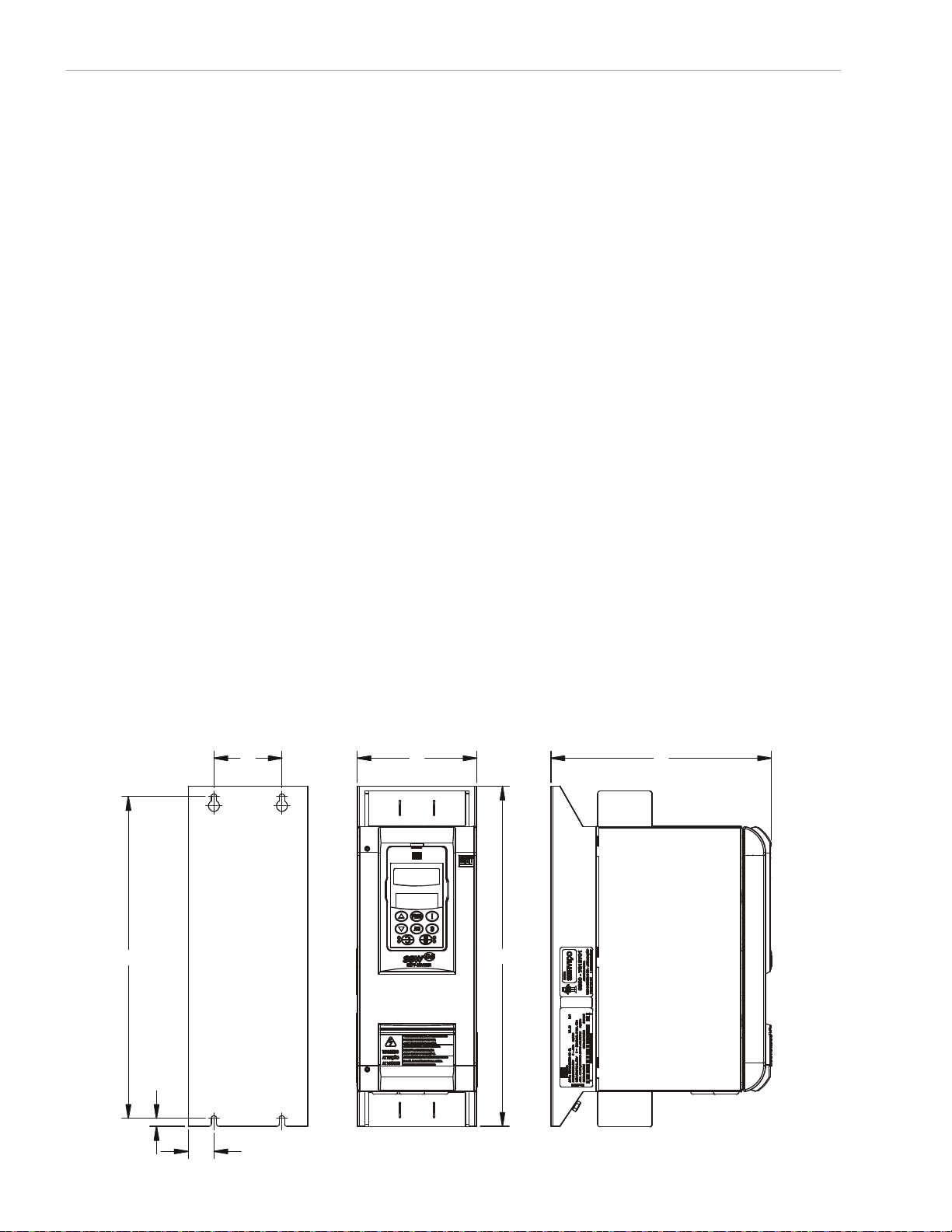
3.1.2 Dimensions of the
Soft-StarterSSW-06
A
The location of the Soft-Starter SSW-06 installation is an important
factorto assure good performance and highproduct reliability.
ForproperinstallationoftheSSW-06Soft-Starter,wemakethefollowing
recommendations:
Avoiddirectexposure tosunlight,rain,excessivemoisture or marine
environment;
Avoidexplosiveor corrosive gases andliquids;
Avoidexcessivevibration,dustormetallicand/oroilparticles intheair.
Allowed Environment Conditions:
Temperature:0ºCto 55ºC (32ºF to 131ºF) –Nominal conditionsfor
models 10A to 820A; 0ºC to 40ºC (32ºF to 104ºF) – Nominal
conditions for models950Ato 1400A.2%currentreduction for each
degreeCelsius above the specification in the nominal conditions.
RelativeAirMoisture: 5% to 90%, non-condensing.
Maximum Altitude:1000m (3,300ft) - nominal conditions.
From 1000mto4000m(3,300ftto13,200ft)-with1%currentreduction
foreach100m(330ft) above1000m (3,300ft).
From 2000m to 4000m (6,600ft to 13,200ft) - with 1.1% voltage
reductionfor each 100m(330ft)above2000m (6,600ft)sealevel.
Degree of Pollution:2 (according toUL508).
Water,condensationor conductivedust/particlesarenotallowedin
the air.
Externaldimensionsandmountingholes followFigure3.1andTable3.1.
W
D
30
B
C
D2
Figure 3.1 - Dimensional Drawings of the Soft-Starter SSW-06
H
CHAPTER3- INSTALLATIONANDCONNECTION
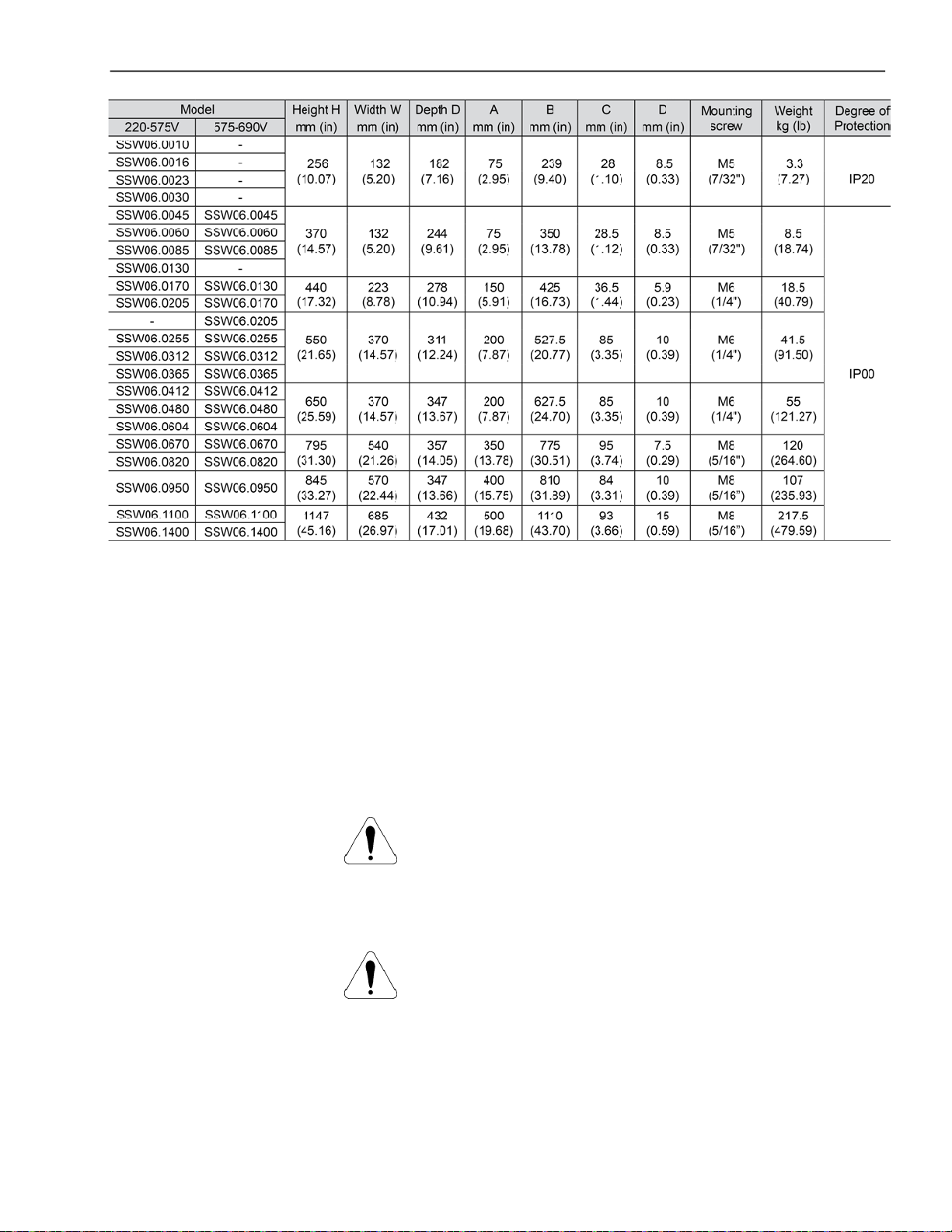
3.1.3 Positioning / Fixing
Table 3.1 - Installation Data with dimensions in mm (in)
Free space for coolingairflowmustbe left open around the SSW-06
Soft-Starter, according to figure 3.2. Thedimensions of each space
are describedin table 3.2.
InstalltheSoft-Starter SSW-06inthe verticalpositionaccordingto the
followingrecommendations:
1) Install the SSW-06 Soft-Starteron a flat surface;
2) Do not place heat sensitive components above the SSW-06 SoftStarter.
ATTENTION!
If the Soft-Starters are installed one next to the other, use minimum
distance B.
When a Soft-Starter is installedaboveanother, use minimumdistance
A+CandavoidtheSoft-Starter abovefrom thehotairthat comesfrom
theSoft-Starter below.
ATTENTION!
Foreseeindependentconduitsor electroducts for physicallyseparating
the signal, control and power conductors (see item 3.2, Electrical
Installation).
31

CHAPTER3- INSTALLATIONANDCONNECTION
C
AYB
Air Flow Outlet
B
Air Flow Inlet
Figure 3.2 - Free spaces for cooling
Model
SSW-06.0010
SSW-06.0016
SSW-06.0023
SSW-06.0030
SSW-06.0045
SSW-06.0060
SSW-06.0085
SSW-06.0130
SSW-06.0170
SSW-06.0205
SSW-06.0255
SSW-06.0312
SSW-06.0365
SSW-06.0412
SSW-06.0480
SSW-06.0604
SSW-06.0670
SSW-06.0820
SSW-06.0950
SSW-06.1100
SSW-06.1400
A
mm(in)
150 (5.90)
150 (5.90)
150 (5.90)
150 (5.90)
150 (5.90)
150 (5.90)
150 (5.90)
150 (5.90)
B
mm(in)
30 (1.18)
30 (1.18)
30 (1.18)
30 (1.18)
30 (1.18)
30 (1.18)
30 (1.18)
100 (3.93)
C
mm(in)
150 (5.90)
150 (5.90)
150 (5.90)
150 (5.90)
150 (5.90)
150 (5.90)
150 (5.90)
150 (5.90)
Y
mm(in)
50 (1.96)
50 (1.96)
50 (1.96)
50 (1.96)
50 (1.96)
50 (1.96)
50 (1.96)
50 (1.96)
Table 3.2 - Recommended free spaces
3.1.3.1Mounting insidea Panel
WhentheSoft-StartersSSW-06areinstalledinpanelsor closedmetallic
boxes, adequate cooling is required to ensure that the temperature
aroundtheinverterwillnot exceed the maximum allowedtemperature.
See dissipated power in the table 3.4.
32

CHAPTER3- INSTALLATIONANDCONNECTION
Use the minimum recommended panel dimensions and its cooling
requirements:
Table 3.3 - Panel Dimensions and Cooling Requirements
NOTE!
The fans recommended in table 3.3 are base on:
- a working cycle of 10 starts per hour with 3 x In of the SSW-06 for
30sat an ambient temperatureof 55°C (131°F) for the modelsfrom
10A to 820A;
- a working cycle of 5 starts per hour with 30s at an ambient
temperature of 40°C (104°F)for the modelsfrom 950A to 1400A.
33
CHAPTER3- INSTALLATIONANDCONNECTION
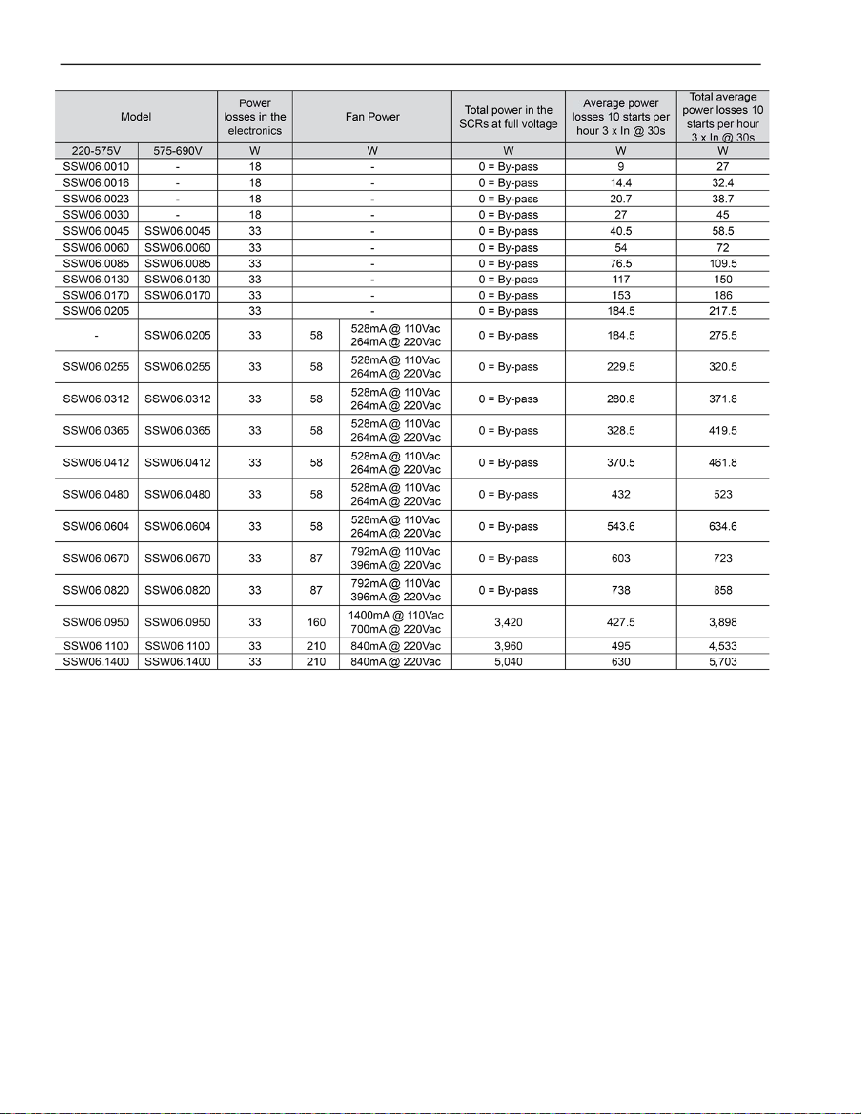
34
Table 3.4 - Power losses for panel fan dimensioning

CHAPTER3- INSTALLATIONANDCONNECTION
tc
Thetotal power losses canbe determined throughtheequationbelow:
trInVtpIpVtcPe
)32.1()32.1()(
Ptd
where:
Pe = power losses at the electronics (W)
tc = working cycle time (s)
Ip = start current (A)
tp = start time (s)
In = current at nominal duty (A), with By-pass In=0
tr = nominal duty time (Full Voltage) (s)
Ptd = total power losses (W)
3.1.3.2 Mountingona Surface
P(W)
I(A)
0
Ip
In
Pe
tp
Figure 3.3 - Soft-Starter SSW-06 working cycle for
tr
tc
power loss determination
t(s)
The figure 3.4 shows the installationof the Soft-Starter SSW-06 on a
mountingplate.
Figure 3.4 - Mounting procedures for the SSW-06 on a flat surface
35
CHAPTER3- INSTALLATIONANDCONNECTION
First install and partiallytighten the mounting bolts, in agreement with
figures3.1 and 3.4and table 3.1, then installtheSoft-StarterSSW-06
and tighten the mounting bolts.
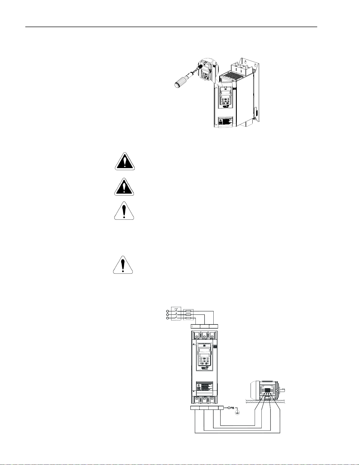
Figure 3.5 - Procedures for keypad removal and front cover
opening for the control connections exposure
3.2 ELECTRICAL INSTALLATION
DANGER!
Be sure that the AC input power is disconnected before making any
terminalconnections.
DANGER!
TheSoft-StarterSSW-06cannotbeusedas anemergencystopdevice.
ATTENTION!
The information below willbe a guideto achieve a proper installation.
Also follow all applicable local standards for electrical installations.
Provide at least a 0.25m (10 in) space between sensitive equipment
andwiringfrom the Soft-Starter SSW-06, andthe cablesbetweenthe
Soft-StarterSSW-06andthemotor.Example:PLC,temperaturewiring,
thermocouple cables, etc.
ATTENTION!
On the first power-up of models 45A to 365A, if a contactor is not
used to isolate the power input, and which will fall out upon under
voltage, then the control supply must be connected first and the
minimum necessary parameters must be programmed after which
the main power may be connected.
Circuit-breaker
T
S
R
Line
Fuses
R/1L1
S/3L2 T/5L3
36
U/2T1 W/6T3 PEV/4T2
Figure 3.6 - Standard power/grounding connections
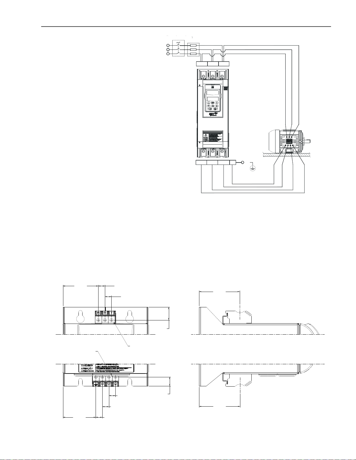
U/2T1 V/4T2 W/6T3 PE
R/1T1 S/3T2 T/5T3
PE
Circuit-breaker
T
S
R
Line
Fuses
CHAPTER3- INSTALLATIONANDCONNECTION
S/3L2
R/1L1
T/5L3
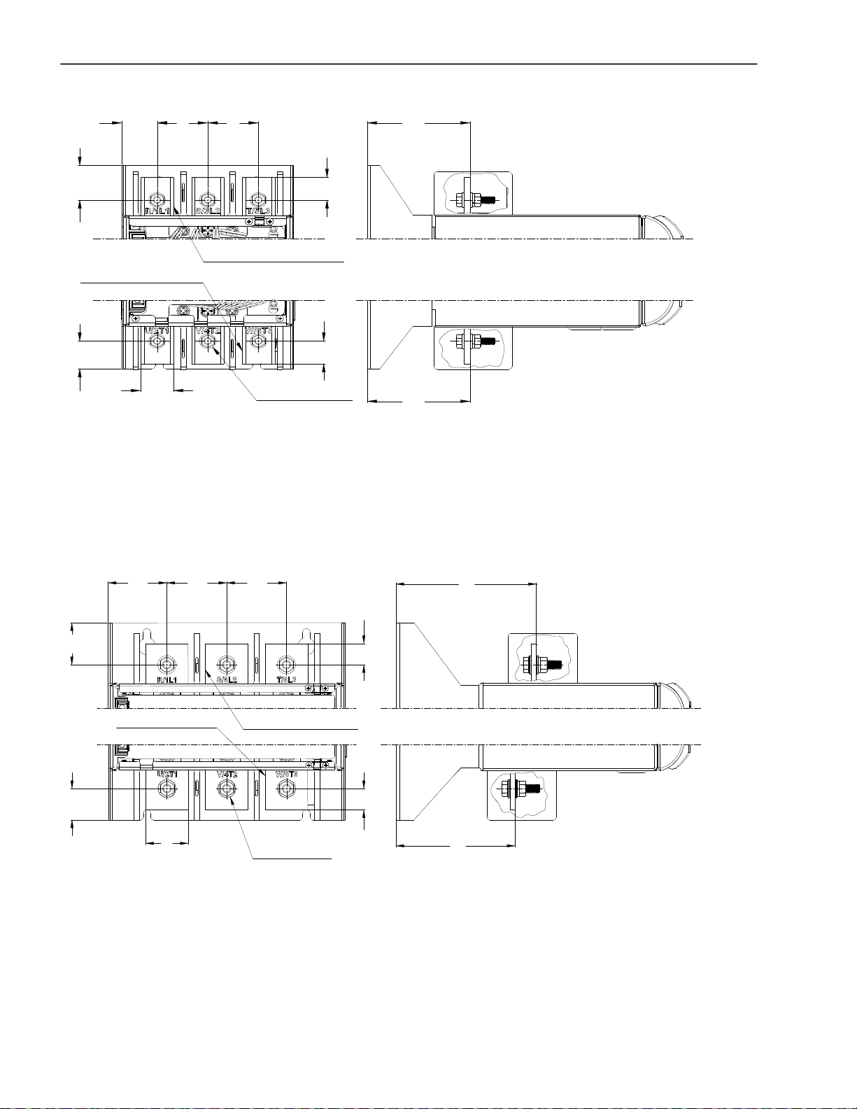
3.2.1 PowerTerminals
a) Models: 10A to 30A
54
(2.12)
OUTPUT TERMINAL
POWER
10(0.39)
10(0.39)
Figure 3.7 - Power/Grounding connections for inside delta motor connection
The power connection terminals can be of different sizes and
configurations,dependingontheSoft-StarterSSW-06modelasshown
in Figures 3.8 and 3.9.
Terminals:
R / 1L1, S / 3L2 and T / 5L3: AC supply line
U / 2T1, V / 4T2 and W / 6T3: Motor connection.
62
(2.44)
20
(0.79)
INPUT TERMINAL
POWER
50
(1.96)
10(0.39)
10(0.39)
10(0.39)
14
(0.55)
62
(2.44)
Figure 3.8 a) - Power Terminals
37
CHAPTER3- INSTALLATIONANDCONNECTION
b) Models: 45A to 130A (220 - 575V) or 45A to 85A (575 - 690V)
27
(1.06)
30.6
20)
(1.
(1.54)
OUTPUT TERMINAL
POW ER
24.5
(0.96)
*Dimensionsin mm (in)
39
(1.54)
INPUT TERMINAL
POW ER
25
(0.98)
39
0
2
(0.79)
20
(0.79)
M6 (6x)
79.5
(3.13)
79.5
(3.13)
c) Models: 170A and 205A (220 - 575V) or 130A and 170A (575 - 690V)
)
39.5
(1.56
29.4
(1.16)
55.3
(2.18)
OUTPUT TERMINAL
POWER
(2.22)
40
(1.57)
56.3
56.3
(2.22)
INPUT TERMINAL
POWER
M8 (6x)
20
0.79)
(
20
(0.79)
*Dimensionsin mm (in)
Figure 3.8 b) c) - Power Terminals
(5.20)
112
(4.41)
132
38
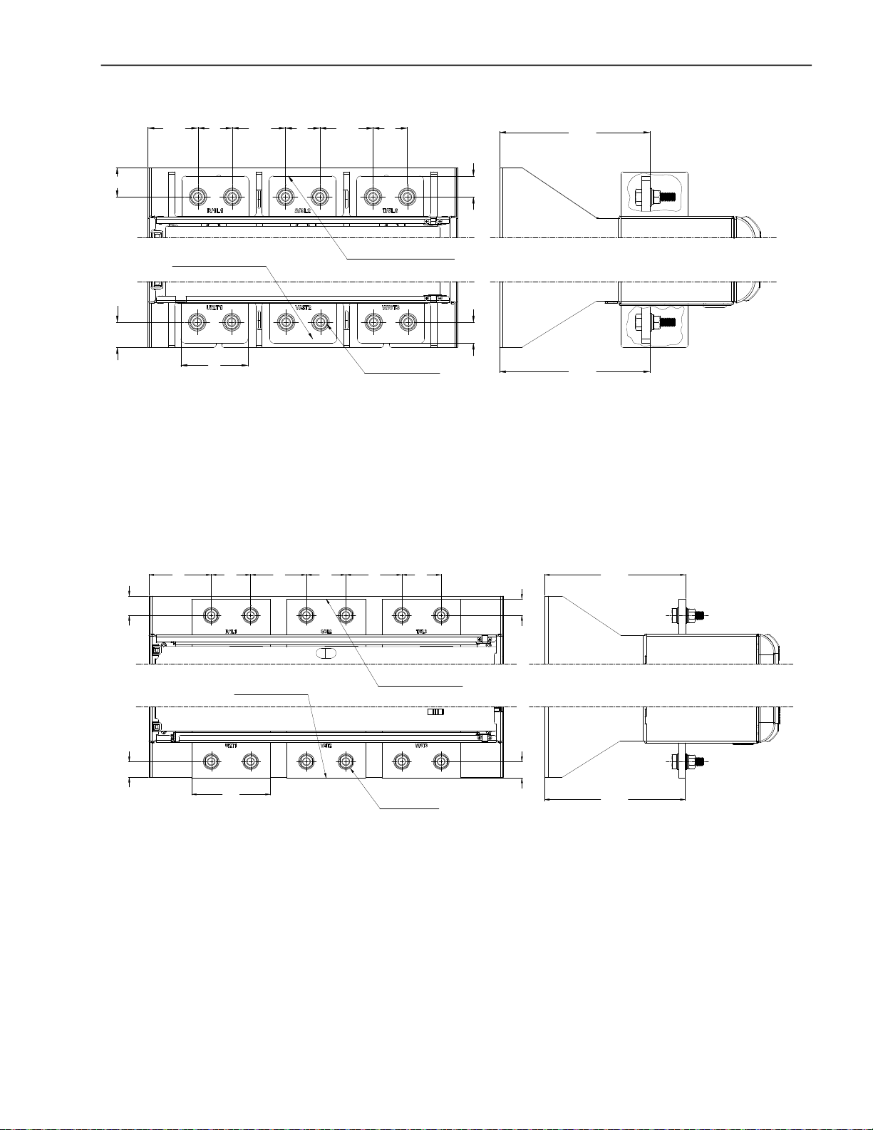
d) Models: 255A to 604A (220 - 575V) or 205A to 604A (575-690V)
CHAPTER3- INSTALLATIONANDCONNECTION
41
(1.61)(2.35) (2.50)
35
(1.38)
OUTPUT TERMINAL
POWER
30
(1.18)
80
(3.15)
*Dimensionsin mm (in)
e) Models: 670A and 820A
63.559.8
(1.61)
41
63.5
41
(1.61)(2.50)
INPUT TERMINAL
POWER
179.5
(7.07)
25
(0.98)(0.98)
25
M10 (12x)
179.5
(7.07)
95
29.7
(3.74)
(1.17)
23.9
(0.94)
*Dimensionsin mm (in)
60 85
(2.36)
120
(4.72)
(3.35)
OUTPUT TERMINAL
POWER
60
(2.36) (2.36)
85
(3.35)
60
INPUT TERMINAL
POWER
M12 (12x)
Figure 3.8 d) e) - Power terminals
214.3
25
(0.98)
25
(0.98)
(8.44)
214.3
(8.44)
39

CHAPTER3- INSTALLATIONANDCONNECTION
f) Models: 950A
M12 (12x)
04)
51.7
(2.
49.798.8
(1.96)
(3.89)
95)
49.5
(1.
53.4 22
(2.10)
(0.87)
*Dimensionsin mm (in)
g) Models: 1100Aand 1400A
110.3 49.7
(4.34)
156
(6.14)
(1.96) (1.96)
100
(3.94)
22
(0.87)
110.3
(4.34)
M10 (6x)
156
(6.14)
49.7
(0.87)
(1.97)
22
50
40
(1.57)
20
INPUT TERMINAL
POWER
(0.79)
14
(0.55)
OUTPUT TERMINAL
POWER
212.2
(8.35)
22
(0.87)
66.1
(2.60)
.3
60
(2.37)
(1.57)
50
(1.97)
40
58
(2.28)
(5.09)
104.5
(4.11)
129.4
*Dimensionsin mm (in)
158
(6.22)
163
(6.42)
40
(1.57)
120
(4.72)
(1.97)
100
(3.94)
158
(6.22)
M12 (12x)
16350
(6.42)
M12 (12x)
40
(1.57)
(1.97)
INPUT TERMINAL
POWER
50
OUTPUT TERMINAL
POWER
Figure 3.8 f) g) - Power terminals
20 40
40
20
(1.57)(0.79)
(1.57)
(0.79)
89
(3.50)
261.8
(10.31)
40
CHAPTER3- INSTALLATIONANDCONNECTION
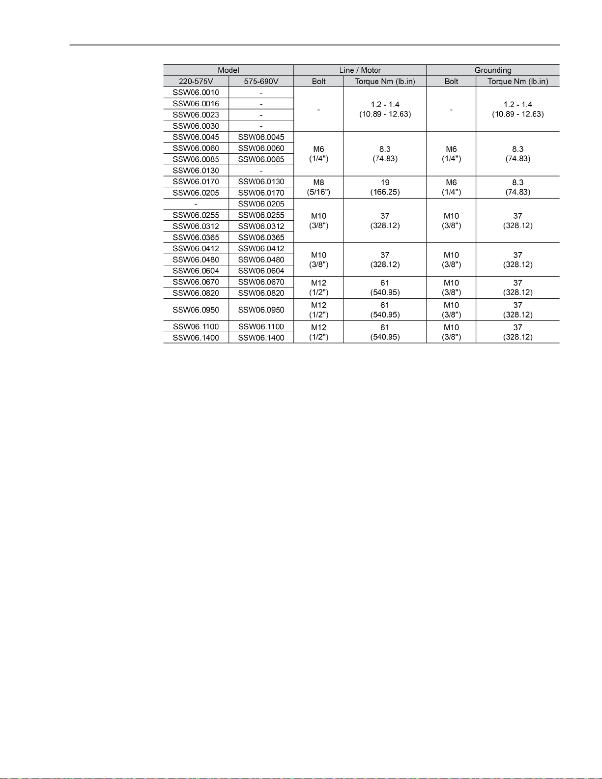
Table 3.5 - Maximum tightening Torque for power connection
41

CHAPTER3- INSTALLATIONANDCONNECTION
FUN SUPPLY
POWER
FUN VOLTAGE
INPUT TERMINAL
OUTPUT TERMINAL
CONTROL
INPUT TERMINAL
POWER
3.2.2 Location of thePower/Grounding, ControlConnectionsandFanVoltageSelection
b) MODELS 45A to 130A
(220 - 575V) or
45A to 85A (575 - 690V)
a) MODELS 10A to 30A
c) MODELS 170A and 205A
(220 - 575V) or
130A and 170A (575 - 690V)
GROUNDING
INPUT TERMINAL
POWER
OUTPUT TERMINAL
POWER
d) MODELS 255A, to 365A
(220 - 575V) or
205A to 365A (575 - 690V)
POWER
CONTROL
GROUNDING
INPUT TERMINAL
POWER
OUTPUT TERMINAL
POWER
e) MODELS 412A to 604A
GROUNDING
POWER
POWER
CONTROL
POWER
f) MODELS 670AAND 820A
42
GROUNDING
POWER
GROUNDING
INPUT TERMINAL
GROUNDING
INPUT TERMINAL
POWER
OUTPUT TERMINAL
POWER
ATTENTION!
SELECTTHEFANVOLTAGEINACCORDANCE
WITHTHEVOLTAGEAPPLIEDTOTHE
TERMINALSX1:33ANDX1:34
!
ATENCION!
SELECCIONARLATENSIONDELOSVENTILADORES
DEACUERDOCONLATENSIONAPLICADAALOS
BORNESX1:33YX1:34
ATENÇÃO!
SELECIONEATENSÃODOSVENTILADORES
DEACORDOCOMATENSÃOAPLICADAAOS
BORNESX1:33EX1:34
X1E
FAN VOLTAGE
SELECTION
110/220V
FAN SUPPLY
POWER
CONTROL
POWER
OUTPUT TERMINAL
POWER
CONTROL
POWER
FAN SUPPLY
FAN VOLTAGE
SELECTION
110/220V
OUTPUT TERMINAL
POWER
SELECTION
110/220V
CONTROL
Figure 3.9 a) to f) - Location of the Power/ Grounding, Control Connections and Fan Voltage Selection

CHAPTER3- INSTALLATIONANDCONNECTION
Figure 3.9 g) and h) - Location of the Power/ Grounding, Control Connections and Fan Voltage Selection
3.2.3 RecommendedPower/ GroundingCables
Thedescribed specifications intables3.6 and 3.7are validonlyforthe
following conditions:
Copper wires for 70°C (158°F) with PVC insulation, with ambient
temperatureof 40°C(104°F),installedin horizontalorverticalholed
conduits, with cables arranged in a single layer.
Nakedor silvercoatedcopperbusbars withroundedges and radius
equal to 1mm with room temperature of 40°C (104ºF) and bus
temperature of 80°C(176ºF).
Note: When external By-pass contactors are applied, use the same
cablesor busbar applied forthe motor connection.
NOTE!
Forcorrectcablesizing, considertheinstallationcondition,themaximum
permittedlinevoltage drop,andfollowelectrical instructionsdefined by
localregulations.
43

CHAPTER3- INSTALLATIONANDCONNECTION
Table 3.6 - Recommended cables or bus bars for standard connection,
according to UL508 and IEC 60092-352
44

CHAPTER3- INSTALLATIONANDCONNECTION
Table 3.7 - Recommended cables or bus bars for delta inside motor connection, according to UL508 and IEC 60092-352
45

CHAPTER3- INSTALLATIONANDCONNECTION
3.2.4 Connection of the Power Supplytothe Soft-Starter
DANGER!
TheAC inputvoltage mustbe compatiblewiththeSoft-StarterSSW-06
nominalvoltage.
DANGER!
Provideapowersupplydisconnectingswitch.Thisdisconnectingswitch
must disconnect the AC input voltage from the Soft-Starter SSW-06,
wheneverrequired (for instanceduringmaintenance services).
DANGER!
If a disconnect switch or a contactor is inserted in the motor supply
line,DO NOT operate these devices witha runningmotor or when the
Soft-Starter SSW-06 is enabled.
ATTENTION!
Controlof overvoltageintheline that suppliesthe Soft-Startermust be
madeusing surge protectionwithavoltageof 680Vac(phasetophase
connection) and energy absorption capacity of 40 joules (for models
from10Ato205A)and80 joules(formodelsfrom255Ato1400A),allfor
220 to 575 Vac models.
3.2.4.1 PowerSupplyCapacity
46
NOTE!
Use wire sizing and fuses as recommended in tables 3.6, 3.7 and 3.9.
The connector tightening torque is as indicated in table 3.5. Use 70ºC
(158ºF)copper wiresonly.
The SSW-06 Soft-Starter is suitable to use in a circuit capable of
supplying at most the current (symmetric Arms) established for each
model, and, respective voltage (V) according to table 3.8. This, when
protected by high speed semiconductor fuses.
Standard
Model
SSW-06.0010
SSW-06.0016
SSW-06.0023
SSW-06.0030
SSW-06.0045
SSW-06.0060
SSW-06.0085
SSW-06.0130
SSW-06.0170
SSW-06.0205
SSW-06.0255
SSW-06.0312
SSW-06.0365
SSW-06.0412
SSW-06.0480
SSW-06.0604
SSW-06.0670
SSW-06.0820
SSW-06.0950
SSW-06.1100
SSW-06.1400
Table 3.8 - Maximum current capacity of the power supply
Connection
220-575V (kA)
5
5
5
5
5
5
5
10
10
10
10
18
18
18
30
30
42
42
85
85
85
Inside - Delta
Connection
220-575V (kA)
-
-
-
10
10
10
18
18
18
30
30
42
42
42
85
85
85
100
100
125

CHAPTER3- INSTALLATIONANDCONNECTION
3.2.4.2 RecommendedFuses
The fuses to be used on the input must be high speed semiconductor
fuses with l2t lower or equal to 75% of the SCR valueindicated in table
3.9. (A2s).
These fuses will protect the SCRs in case of a short-circuit. Normal
fuses can also be used, instead of the high speed, which will protect
the installation from short-circuits, but the SCRs will not be protected.
Model
SSW-06.0010
SSW-06.0016
SSW-06.0023
SSW-06.0030
SSW-06.0045
SSW-06.0060
SSW-06.0085
SSW-06.0130
SSW-06.0170
SSW-06.0205
SSW-06.0255
SSW-06.0312
SSW-06.0365
SSW-06.0412
SSW-06.0480
SSW-06.0604
SSW-06.0670
SSW-06.0820
SSW-06.0950
SSW-06.1100
SSW-06.1400
Standard
Connection
In (A)
50
50
80
80
125
125
200
250
450
500
500
500
550
700
900
900
900
1400
1600
1600
2000
Table 3.9 - Recommended Fuses
Delta-Inside
Connection
In (A)
-
-
-
125
160
315
350
500
550
700
700
700
1250
1400
1600
1600
2000
2200
2500
3000
I²t of the SCR
(kA2S)
0.72
0.72
4
4
10
15
80
84
245
320
238
238
320
1452
4250
4250
4250
4250
14000
14000
15125
47

CHAPTER3- INSTALLATIONANDCONNECTION
3.2.5 Connectionofthe SSW-06Soft-Starter tothe motor
DANGER!
Powerfactor correction capacitorsshould never be fitted to the output
of the Soft-Starter SSW-06 (U / 2T1, V / 4T2 and W / 6T3).
ATTENTION!
For the protection based on the current reading and indication to work
correctly,in case of overloadprotection,thenominalcurrentof the motor cannot be lower than 30% of the nominalcurrent of the SSW-06
Soft-Starter.
It is not recommended to use motors with the load working duty lower
than 50% of its nominal current.
NOTE!
Use wire sizingand fuses as recommended in Table 3.6, 3.7 and 3.9.
The connector tighteningtorque is as indicated in Table3.5.Use 70ºC
(158ºF)copper wiresonly.
NOTE!
Soft-Starter SSW-06 is provided with anelectronic protection against
motor overload. This protection must be set according to the specific
motor. When several motors are connected to the same Soft-Starter
SSW-06, use individualoverload relays for each motor.
The SSW-06 Soft-Starter can be connected to the motor in two ways,
according to items 3.2.5.1 and 3.2.5.2.
3.2.5.1 StandardThree-Wire Connection (P150=0=Inactive)
The standard 3 wire connection allows the SSW-06 Soft-Starter line
current to be equal to the motor current.
R
S
T
N
PE
R
U
S
V
4/U2
6/W2
1/U1
3/W1
Figure 3.10 - Soft-Starter SSW-06 with standard connection
T
2/V1
5/V2
R
S
T
N
PE
1/U1
2/V1
4/U2
S
V
5/V2
6/W2
3/W1
R
W
U
T
W
48

CHAPTER3- INSTALLATIONANDCONNECTION
3.2.5.2 InsideDelta MotorConnection (P150=1=Active)
Inthiskind of connection,theSSW-06 Soft-Starter linecurrentisequal
to approximately58% of the nominal current of the motor.
R
S
T
N
PE
S
4/U2
U
1/U1
R
R
6/W2
3/W1
Figure 3.11 - Soft-Starter SSW-06 Inside Delta Motor Connection
R
S
T
N
PE
S
10/U4
S
2/V1
V
5/V2
W
T
T
S
2/V1
3/W1
V
8/V3
5/V2
W
11/V4
T
T
4/U2
7/U3
U
1/U1
R
12/W4
R
6/W2
9/W3
Figure 3.12 - Soft-Starter SSW-06 Inside Delta Motor Connection - motor with
double delta series connected
R
S
T
N
PE
S
4/U2
1/U1
10/U4
U
7/U3
R
12/W4 9/W3
R
S
V
2/V1
8/V3
11/V4
5/V2
W
T
T
6/W2 3/W1
Figure 3.13 - Soft-Starter SSW-06 Inside Delta Motor Connection - motor with
double delta parallel connected
49

CHAPTER3- INSTALLATIONANDCONNECTION
ATTENTION!
For inside delta motor connection, the motor must have a nominal
voltagefor deltaconnection.
Theinside deltamotorconnection cannotbeusedfor 690Vlinevoltage.
NOTES!
1) For motor inside delta connection, the SSW-06 Soft-Starter
connection cables to the power supply, fuses and/or the main
contactormustsupportthenominalcurrentof the motor. Themotor
connection cables to the Soft-Starter and/or the external By-pass
contactor connection must support 58% of the nominal current of
themotor.
2) Due to the presence of high currents and large cable size
requirements, we also recommend the use of copper busbars for
connecting the Soft-StarterSSW-06 to the power supply.
3) Duringstarting,themotorcurrentinrelationtotheSoft-Startercurrent
is1.50.However,at full voltage(afterthestarttimeof the motor) the
current relationis 1.73.
ATTENTION!
Payattentiontothe connectionof themotortotheSSW-06Soft-Starter,
respecttheconnection diagramsshowninthefiguresaboveaccording
to the type of motor windings. If it is necessary to change the motor
rotating direction, only invert the SSW-06 Soft-Starter connections to
the power supply.
Keepthe electronics turned off during the connection changes.
3.2.6 GroundingConnections
ATTENTION!
EnsurecorrectsettingofParameterP150beforethemotor is switched
ON.Soft-StarterSSW-06maybedamaged,whenthisparametersetting
is not correct.
P150 Action
0 (Inactive) Soft-Starter SSW-06 with standard connection to motor
1 (Active) Soft-Starter SSW-06 with inside delta motor connection
Table 3.10 - Connection of the Soft-Starter to the motor
DANGER!
TheSoft-Starter SSW-06 must begroundedfor safetypurposes(PE).
Theearthorground connectionmustcomplywiththelocalregulations.
For grounding, use cables with cross sections as indicated in Table
3.6. Make the ground connection to a grounding bar or to the general
groundingpoint(resistance 10 ohms).
DANGER!
TheACinputfor the Soft-StarterSSW-06 must be grounded.
DANGER!
Donotusetheneutralconductor forgroundingpurposes.Usea specific
groundconductor.
50
ATTENTION!
Do not share the ground wiring with other equipment that operate with
highcurrents(forinstance,highvoltagemotors,weldingmachines,etc.).
When more than one Soft-StarterSSW-06 is used, see figure 3.14.

CHAPTER3- INSTALLATIONANDCONNECTION
3.2.7 Fan Connections
Groundingbar
Internalto thePanel
Groundingbar
Internalto thePanel
Figure 3.14 - Grounding connections for more than one
Soft-StarterSSW-06
EMI – Electromagnetic interference:
TheSoft-StarterSSW-06isdeveloped to beusedinindustrial systems
(ClassA) as per Norm EN60947-4-2.
It’s necessary to have a distance of 0.25m (10in) between the SoftStarterSSW-06controlcablesandmotorcables.Example:PLCwiring,
temperaturecontrollers, thermocouplecables,etc.
Grounding the motor frame:
Alwaysgroundthemotor frame. Groundthe motor in the panelwhere
the Soft-StarterSSW-06 is installed.The Soft-StarterSSW-06 output
wiring to the motor must be laid separately from the input wiring, as
well as from the control and signal cables.
Availableinmodels greater than255A.
The nominal voltageof the fans can be selected in models from 255A
to 820A.
Formodels from950Ato1400Athevoltageselectionisfixed, according
to the product specification, refer to item 2.4.
SEL EÇÃO
Voltage Selection
DE TE NSÃ O
110/220 V
110/220V
ATTENTION!
SELECT THE FAN VOLTAG E IN AC CORDANCE
WITH THE VOLT AGE AP PLIED TO THE
TERMINALS X1: 33 AND X1 :34
!
ATENCION!
SELECCIONAR L A TENSIO N DE LOS VENTILA DORES
DEAC UERDO C ON LA TENSION A PLICADA A LOS
BORNES X1:3 3 Y X1:34
ATENÇÃO!
SELECIONE A TE NSÃO DOS VENTI LADORES
DEAC ORDO C OM A TENS ÃO APLIC ADA AOS
BORNES X1:33 E X1:34
X1E
Fan
ALIMEN TAÇÃO
Fan Power Supply
VENTILA DO R
Figure 3.15 - Selection of the Fan Voltage
Connector X1E pins 33 and 34. More detailssee figure 3.16.
51
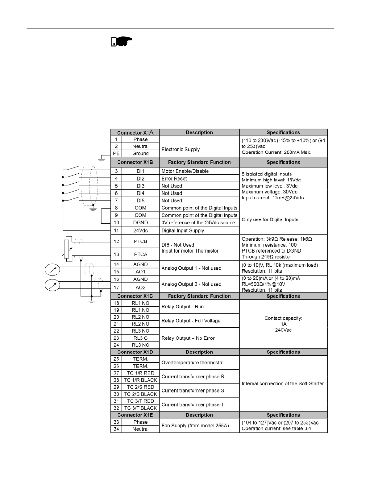
CHAPTER3- INSTALLATIONANDCONNECTION
NOTE!
For models from 255A to 820A the fans are switched on if the heatsink
temperatureis above70ºC(158ºF).Do not forgettoconnectthefanpower
supply and select the fan supply voltage for the models higher or equal
than255A.
3.2.8 SignalandControl Connections
PTC
Thesignalconnections (analogoutputs)andcontrol(digitalinputsandrelay
outputs) are madeontheelectronicboardconnectors.
Connectors:
CCS6andCPS61 on the models10Ato30A.
CCS6andCPS63orCPS66onthemodels45Ato365Aand950A to1400A.
CCS6andCPS64 or CPS65 on themodels 412Ato820A.
52
Note: NC = NormallyClosedContact
NO =Normally Open Contact
C= Common
Figure 3.16 - Control Terminal Description

CHAPTER3- INSTALLATIONANDCONNECTION
X1B X1C X2
X1A
XO
To be used for grounding of shield of
the signal and control cables
Figure 3.17 - Control connector positions
X1D
For signal and control wire installation, adopt the following
procedures:
1) The connections of the SSW-06 digital inputs can be carried out in
severalways.Theycan be suppliedbyauxiliaryinternal +24Vdcsource
byusingthe0Vasacommonpointorbythe+24Vdcsource.Depending
on the application requirements,they can also be supplied by external
+24Vdc source, connected to PLCs, by using the 0V as common
point or by the +24Vdc source:
Connector X1B
3 DI1
4 DI2
5 DI3
6 DI4
7 DI5
8 COM
9 COM
10 DGND
11 24Vdc
Connector X1B
3 DI1
4 DI2
5 DI3
6 DI4
7 DI5
8 COM
9 COM
10 DGND
11 24Vdc
Figure 3.18 - Connection diagram of the digital inputs using the auxiliary internal source
Connector X1B
3 DI1
4 DI2
5 DI3
6 DI4
7 DI5
+
24Vdc
Figure 3.19 - Connection diagram of the digital inputs using an external source
8 COM
9 COM
10 DGND
11 24Vdc
24Vdc
Connector X1B
3 DI1
4 DI2
5 DI3
6 DI4
7 DI5
8 COM
9 COM
+
10 DGND
11 24Vdc
53

CHAPTER3- INSTALLATIONANDCONNECTION
NOTE!
1) The auxiliaryelectronic powersupplyoftheSSW-06Soft-Starter of
+24Vdc shall only be used for the supply of the digital inputs.
2) The SSW-06 Soft-Starterfactorydefaultis with the pins 8 and 10 of
theX1Bconnectorbridged(wire bridge).
3) Cable cross section (0.5 to 1.5) mm2.
4) Maximum torque: 0.50 N.m (4.50 ibf.in).
5) X1B wiring must be connected with shielded cables and installed
separately from other wiring (power, control at 110V/220V, etc.),
accordingto Table3.11.
Ifthe crossingofthese cables is unavoidable,installthemperpendicular, maintaining a minimum separation distance of 5cm (2 in) at the
crossing point.
Wiring Length Min. separation distance
30 m (98.4 ft) 10 cm (3.94 in)
> 30 m (98.4 ft) 25 cm (9.84 in)
Table 3.11 - Wiring separation distances
Connect the shield as shown below:
Soft-Starter side
Connect to ground
Screw located on the CCS6 board
Figure 3.20 - Shield connection
Insulate with tape
Do not ground
6) For wiring distances longer than 50m (150ft), it is necessary to use
galvanicisolatorsforthe X1B:3...17signals.
7) Relays, contactors, solenoids or electromagnetic braking coils
installednearSoft-Starters can generate interference in the control
circuit.Inordertoeliminatethisinterference,connectRCsuppressors
inparallelwiththecoilsof ACrelays.Connect a free-wheelingdiode
in case of DC relays/coils.
54
8) Whenanexternalkeypadisused(RefertoChapter 9),separatethe
cable that connects the keypad to the Soft-Starter SSW-06 from
othercables,maintaininga minimumdistanceof10cm(4in)between
them.
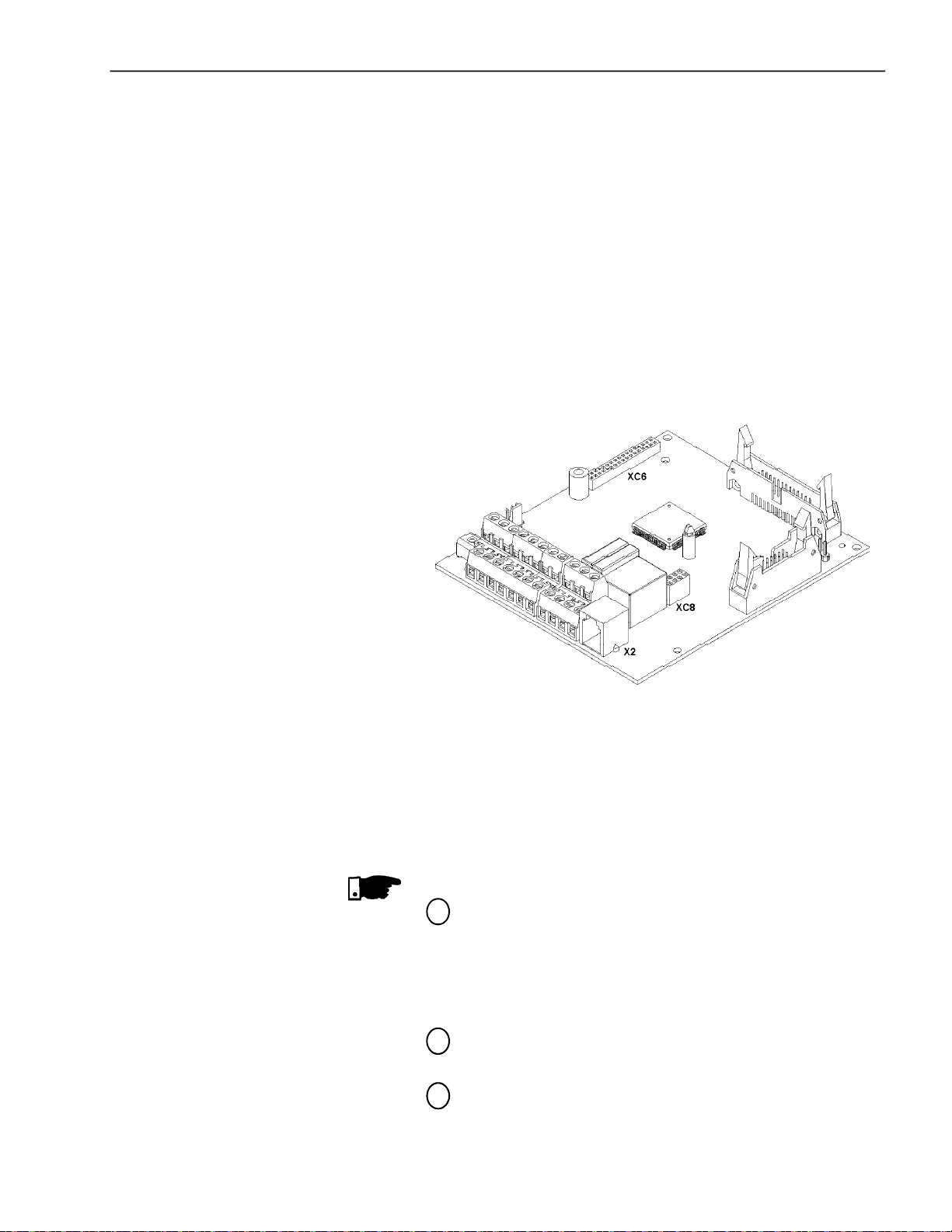
CHAPTER3- INSTALLATIONANDCONNECTION
3.2.9 RS-232,X2 Serial CommunicationConnection
3.2.10 XC8 Serial CommunicationBoard Connection
3.2.11 XC6 Fieldbus
CommunicationBoard
Connection
This connector is used to make a standard RS-232 communication
linebetween the Soft-StarterSSW-06 and a PC and/or PLC.
For more details see the Serial Communication Manualof the
Soft-StarterSSW-06.
An optional board of serial communication, standard RS-485 with
galvanic insulation, or USB, can be attached to this connector.
For more details see the Serial Communication Manualof the
Soft-Starter SSW-06 andchapter 9.
An optional Profibus DP or DeviceNet Communication board can be
attached to this connector.
For more details see the Profibus DP or DeviceNet Communication
Manualof the Soft-StarterSSW-06 and chapter 9.
3.3 RECOMMENDED SET-UPS
Figure 3.21 - X2, XC6 and XC8 Connector
In this item some suggestive set-ups are presented, which can be
used completelyor in part to elaborate the desired control.
The main warnings, for all the suggestive set-ups, listed below, are
relatedinthe diagrams throughtheirrespectivenumbers.
NOTES!
For the protection of all of the electrical installation, the use of
1
fuses or circuit breakers in the main power supply circuit is
necessary.
The use of high speed semiconductorfuses are not necessary
for the functioning of the SSW-06 Soft-Starter, but its use is
recommended for the complete protectionof the thyristors.
The transformer “T1” is optional and should be used when the
2
linevoltage is differentfrom the electronics and fan voltage;
To protect the motor against destruction by possible short-
3
circuits in the power circuit of the Soft-Starter SSW-06 use an
isolating contactor (K1) or circuit-breaker (Q1);
55

CHAPTER3- INSTALLATIONANDCONNECTION
4
5
6
7
8
9
X1E(33and 34)isonlyavailable on themodelsfitted withcooling
fans;
Forintegralmotorprotectiontheinstallationofoneor morePTC
thermistors (PTC atDI6) or thermostats(external fault at DI4 to
DI6)isrecommended;
Remember that when a command via two-wire digital input is
used(the switchisnormallyopen withretention),everytime the
power supplyreturns,afteranyfault,themotorstarts immediately
if the switch remains closed;
Incaseofmaintenanceservices, removethepowersupplyfuses
or disconnect the power supply, thus ensuring complete
equipmentdisconnectionfrompower.
An emergency stop can be obtained by disconnecting the
electronics power supply.
The contactors must be of the same model and must support
themotorstartingcurrent.Forsafetyreasons,auxiliarycontacts
must be used to keep both contactors from closing at the same
time.
Use a digital input set to “General Enable” to disable the motor
10
withoutbraking. Use adigitalinputsetto“NoBraking”,for safety
reasons, with the possibility of fitting a motor stop sensor to
disablethe braking.
The use of an external By-passcontactor is optional for models
11
950Ato 1400A that do not have an internal By-pass contactor.
This contactor is also recommended,in models with an internal
By-pass,for use in applications wherethe motor can frequently
present a locked rotor during the full operation cycle.
To maintainthe current indications and protections, when using
12
the external By-pass contactor, it is necessary to place the
current transformers on the Soft-Starter output. The current
transformers must be placed in the correct positions and
directions as indicated. For more details see chapter 9.6.
56
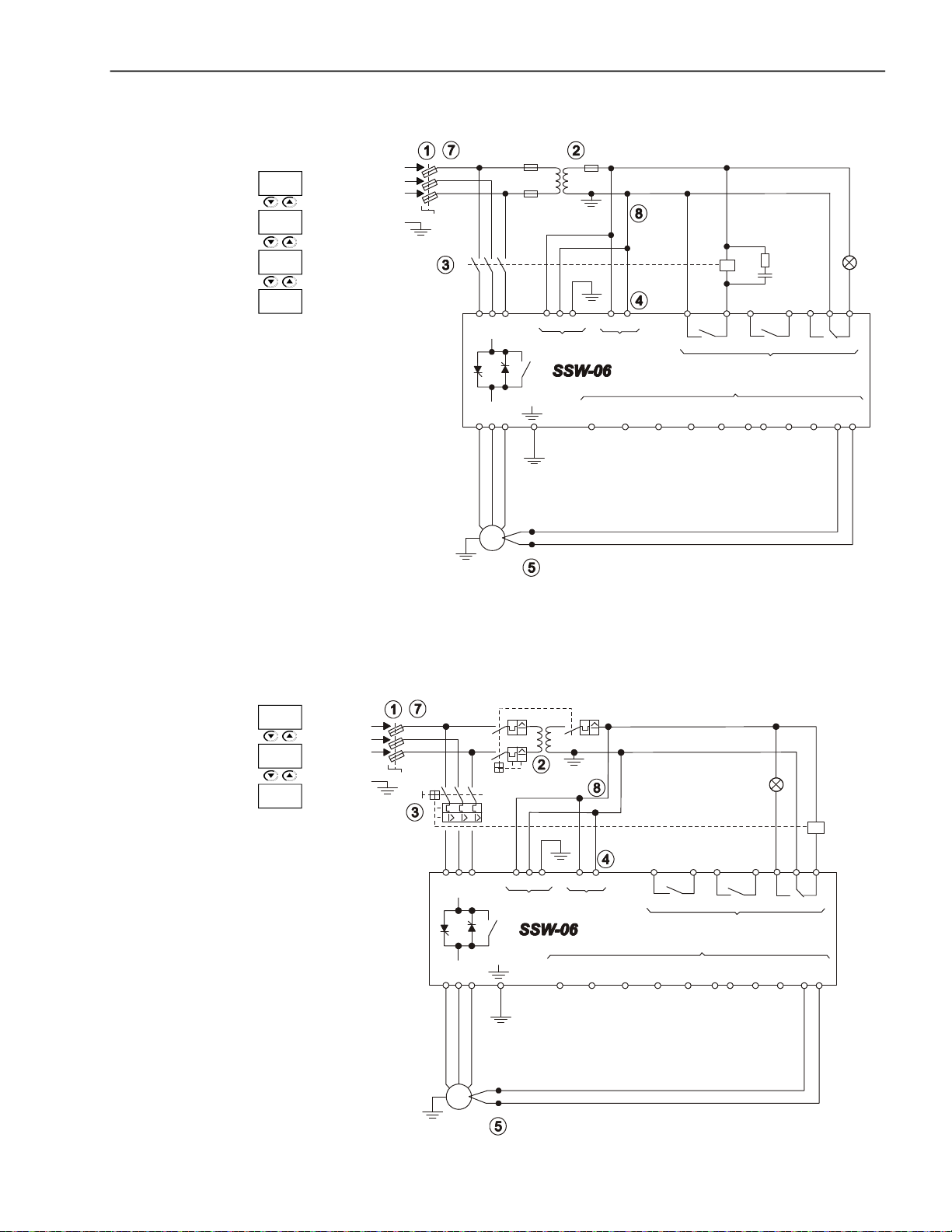
CHAPTER3- INSTALLATIONANDCONNECTION
3.3.1 Recommended Set-upsusing KeypadCommand withIsolatingContactor
P220 =0
P229 =0
P277 =1
P279 =6
See notes in the item 3.3
Figure 3.22 - Recommended Set-ups using Keypad command with isolating contactor
+ t
PTC
1 2 PE
o
T1
33 34
X1EX1A
Dl1
Dl24Dl35Dl4
3
18
19
RL1 RL2
Dl5
6
K1
20
21 22
X1C
X1B
7
COM
8 9
0V
24V
10
11
23 24
RL3
PTC
B A
12 13
Fault
R
S
T
PE
K1
R S T
U V W
M
3~
3.3.2 Recommended Set-ups usingKeypadCommand with Circuit-breaker
Q2
+ t
PTC
1 2 PE
o
X1A
T1
19
Dl1
Dl3
18
Dl4
6
5
33 34
X1E
Dl2
3
4
RL1
Dl5
20
X1B
COM
7
8 9
P220 =0
P229 =0
R
S
T
PE
P279 =7
See notes in the item 3.3
Q1
R S T
U V W
M
3~
Fault
21 22 23
RL2
X1C
Q1
Circuitbreaker with
undervoltage
release
24
RL3
24V
11
PTC
B A
12 13
0V
10
Figure 3.23 - Recommended Set-ups using Keypad command with circuit-breaker
57
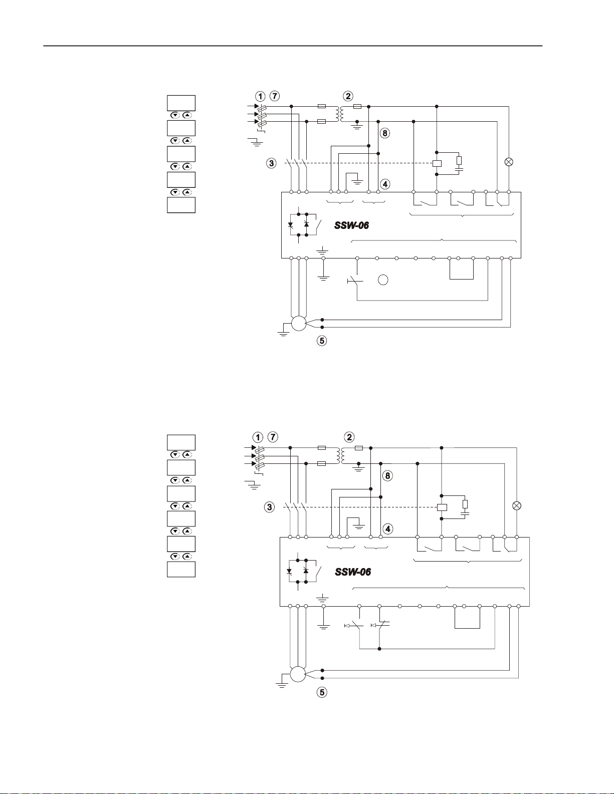
CHAPTER3- INSTALLATIONANDCONNECTION
6
3.3.3 Recommended Set-upswithCommand viaTwo-wire DigitalInputs
P220 =1
P230 =1
P263 =1
P277 =1
P279 =6
See notes in the item 3.3
Figure 3.24 - Recommended set-ups with command via two-wire digital inputs
+ t
PTC
T1
RL3
PTC
B A
12 13
Fault
K1
Dl3
18
Dl46Dl5
5
33 34
X1EX1A
Dl2
Dl1
4
3
Start/
Stop
o
RL1
19
X1B
7
20 21
RL2
X1C
COM
8 9
22 23 24
0V
10
24V
11
R
S
T
PE
K1
R S T 1 2 PE
U V W
M
3~
3.3.4 Recommended Set-upswithCommandviaThree-wireDigital Inputs
P220 =1
P230 =1
P263 =2
P264 =1
P277 =1
P279 =6
See notes in the item 3.3
R
S
T
PE
K1
R S T
U V W
M
3~
T1
1 2 PE 33 34
o
+ t
PTC
Dl1
18 19
X1EX1A
Dl2
Dl3
4
3
Start
RL1
Dl4
5
6
Stop
Dl5
X1B
7
K1
20
X1C
COM
8 90V10
RL2
Fault
21
22 23
24V
11
RL3
24
PTC
B A
12 13
Figure 3.25 - Recommended set-ups with command via three-wire digital inputs
58

CHAPTER3- INSTALLATIONANDCONNECTION
3.3.5 Recommended Set-upswithCommandvia Three-wireDigitalInput andInsideDelta MotorConnection
P150 =1
P220 =1
P230 =1
P263 =2
P264 =1
P277 =1
P279 =6
See items 3.2.5.2 and 3.3
Figure 3.26 - Recommended set-ups with command via three-wire digital input and inside
+ t
PTC
1 2 PE
o
T1
Fault
23
24
RL3
PTC
B A
12 13
Dl1
K1
19
33 34
X1EX1A
Dl2
4
3
Start
18
RL1
Dl4
X1B
Dl5
6
7
Dl3
5
Stop
20
COM
8 9
RL2
X1C
21 22
0V
10
24V
11
R
S
T
PE
K1
R S T
U V W
M
3~
delta motor connection
3.3.6 Recommended Set-ups withCommandvia Three-wireDigitalInput or Serial Communication
+ t
PTC
1 2 PE
o
T1
X1A
Dl1
K1
18
19
33 34
X1E
Dl2
4
3
Start
Dl4
Dl3
5
Stop
20
RL1
6
RL2
X1C
X1B
Dl5
COM
7
8 9
Local
Remote
P220 =4
P229 =1
P230 =2
P263 =2
P264 =1
P277 =1
P279 =6
See notes in the item 3.3
R
S
T
PE
K1
R S T
U V W
M
3~
21
0V
10
22 23 24
RL3
24V
11
12 13
PTC
B A
X2
Fault
PC
Figure 3.27 - Recommended set-ups with command via three-wire digital input or serial
communication
59

CHAPTER3- INSTALLATIONANDCONNECTION
10
3.3.7 Recommended Set-ups withCommand viaThree-wireDigitalInput orFieldbus Communication
P220 =4
P229 =1
P230 =3
P263 =2
P264 =1
P277 =1
P279 =6
See notes in the item 3.3
Figure 3.28 - Recommended set-ups with command via three-wire digital input or fieldbus
+ t
PTC
T1
1 2 PE
o
Dl1
K1
19
33 34
X1EX1A
Dl2
3
Start
18
Dl3
4
Dl4
5
Stop
20
RL1 RL2
X1B
Dl5
7
6
Local
Remote
COM
8 9
X1C
21
22
24V
0V
11
10
Fault
23
24
RL3
X2
PTC
B A
12 13
PLC
R
S
T
PE
K1
R S T
U V W
M
3~
communication
3.3.8 Recommended Setup with Command viaDigitalInputsand directionof rotation
P220 =1
P230 =1
P231 =1
P263 =2
P264 =1
P266 =1
P277 =4
P278 =4
P279 =6
See notes in the item 3.3
R
S
T
PE
K2
K1
U V W
M
3~
R S T
+ t
PTC
T1
1 2 PE
o
Dl1
K1
19
33 34
X1EX1A
Dl2
4
3
Start
18
Dl3
5
Stop
RL1 RL2
X1B
Dl5
Dl4
7
6
Rotation
Direction of
20
COM
8 9
X1C
K2
21
22
24V
0V
11
10
23
RL3
24
PTC
B A
12 13
Fault
Figure 3.29 - Recommended Setup with Command via Digital Inputs and direction of rotation
60

CHAPTER3- INSTALLATIONANDCONNECTION
10
3.3.9 Recommended Setup with Command viaDigitalInputsand ReverseBraking
See notes in the item 3.3
P220 =1
P230 =1
P263 =2
R
S
T
PE
K2
K1
T1
K1
K2
P264 =1
19
P265 =1
P266 =5
P277 =4
P278 =4
P279 =6
P500 =1
R S T
U V W
M
3~
+ t
PTC
1 2 PE
o
Dl1
3
33 34
X1EX1A
Dl2
Dl35Dl46Dl57COM
4
Start
Stop
18
RL1 RL2
Without
Gen. Enable
20
X1C
X1B
8 9
Braking
23
21
24
22
RL3
PTC
24V
0V
B A
11
10
12 13
Figure 3.30 - Recommended Setup with Command via Digital Inputs and Reverse Braking
Fault
3.3.10 Recommended Setup withCommandviaDigitalInputsand Optimal Braking
P220 =1
P230 =1
P263 =2
P264 =1
P265 =1
P266 =5
P277 =1
P279 =6
P500 =2
See notes in the item 3.3
R
S
T
PE
K1
R S T
U V W
M
3~
+ t
PTC
1 2 PE
o
T1
K1
19
Dl1
33 34
X1EX1A
Dl2
4
3
Start
18
Dl3
Dl4
5
Stop
Gen. Enable
20
RL1 RL2
X1B
Dl5
7
6
Without
Braking
X1C
COM
8 9
Fault
23
21
0V
10
22
24V
11
RL3
24
PTC
B A
12 13
Figure 3.31 - Recommended Setup with Command via Digital Inputs and Optimal Braking
61

CHAPTER3- INSTALLATIONANDCONNECTION
3.3.11 RecommendedSetup with Command viaDigitalInputs and DC-Braking
See notes in the item 3.3
P220 =1
P230 =1
P263 =2
R
S
T
PE
K1
T1
K1
P264 =1
P265 =1
P266 =5
P277 =1
R S T
U V W
1 2 PE
Dl1
3
33 34
X1EX1A
Dl2
18
19
RL1 RL2
Dl3
4
5
Dl4
Dl5
7
6
20
X1B
21
X1C
COM
8 90V10
P278 =5
Stop
Start
Without
Braking
Gen. Enable
P279 =6
P500 =3
K2
o
+ t
M
3~
PTC
Figure 3.32 - Recommended Setup with Command via Digital Inputs and DC-Braking
24V
11
23
RL3
24
PTC
B A
12 13
Fault
K2
22
3.3.12 Recommended SetupwithCommandviaDigitalInputs and ExternalBy-passContactor
+ t
PTC
T1
1 2 PE
Red
o
X1D
2728293031
Black
Black
Red
33 34
X1EX1A
Black
Red
32
18
RL1 RL2
Dl13Dl24Dl35Dl46Dl57COM
Start
Stop
19
K1
20 21
X1C
X1B
8 9
24V
11
23
RL3
24
PTC
B A
12 13
Fault
K2
22
0V
10
P140 =1
P220 =1
P230 =1
P263 =2
P264 =1
P277 =1
P278 =3
P279 =6
See notes in the item 3.3
R
S
T
PE
K1
R S T
K2
U V W
M
3~
62
Figure 3.33 - Recommended Setup with Command via Digital Inputs and External By-pass
Contactor

3.3.13 Symbols
Electrical connection between
two signals
ConnectionTerminals
CHAPTER3- INSTALLATIONANDCONNECTION
Fuse
Thyristor/SCR
Coil - Relay, Contactor
Normally Open Contact (NO)
Indicatorlight
Circuit-breaker
(opens under load)
Resistor
Capacitor
3~
M
Three-phase Motor
Emergency Button
Transformer
N.O. Contact (with retention)
Normally Closed (NC) Push-button
Normally Open (NO) Push-button
Circuit-breaker with under voltage
release
63

CHAPTER3- INSTALLATIONANDCONNECTION
3.4 EUROPEANDIRECTIVES FORELECTROMAGNETIC COMPATIBILITY REQUIREMENTSFOR INSTALLATION
3.4.1 Installation
The SSW-06 series Soft-Starters were designed considering all the
safety and electromagnetic compatibility aspects.
SSW-06 Soft-Starters do not haveanyintrinsic functionif they arenot
connected to other components (for example, with a motor). For this
reason, the basic product does not have the CE label indicating
conformity with the electromagnetic compatibility directive.
Theend user takes personalresponsibilityforthe EMC complianceof
the whole installation.However, when installed according to the
recommendations described in the User’s Guide and including the
recommendedfilters/EMCmeasurestheSSW-06fulfillallrequirements
of the EMC Directive (2004/108/EC),as definedbyProduct Standard
EN60947-4-2(2000) +A1(2002) - “low-voltageswitchgear andcontrol-
gearpart4.2:Ac Semi-conductorMotorcontrollers andStarters”specific
standard for drives.
Theconformityof thewholeSSW-06 seriesis based on tests of some
representative models. A Technical Construction File (TCF) was
checked and approved by a competent body.
ToinstalltheSoft-Starter(s)inconformitywiththeEN60947-4-2standard,
it is necessary to attend the following requirements:
1) The cables used for control (inputs and outputs) and signal wiring
must be armored or installed in metallic electroducts (conduits) or
inmetallic channels with equivalentattenuation.
2) It is importanttofollowtherecommendations for earthingpresented
in this manual.
3) Models10Ato1400ASSW-06 Soft-Starters areclassifiedforusein
“ClassA”,individual use with no need of external filters or armored
powercables.
Description of the conducted emission classes according to
StandardEN60947-4-2 (2000)+ A1(2002):
- Class B: residential environment (first environment), unrestricted
distribution.
- ClassA:industrialenvironment(secondenvironment),unrestricted
distribution.
NOTE!
The declaration of conformity CE is available on the website
www.weg.net or on the CD, which comes with the products.
64

CHAPTER 4
KEYPAD OPERATION
This Chapter describes the operation of the standard Keypad of the
Soft-StarterSSW-06,providingthe followinginformation:
General KeypadDescription;
Use of the Keypad;
Soft-Starter SSW-06Parameterorganization;
Parameter programming;
Description of the Status Indicators.
4.1 DESCRIPTIONOFTHE KEYPAD(HMI-SSW06)
ThestandardSoft-StarterSSW-06Keypad hastworeadoutdisplays: a
LED readout with a 4 digit, seven-segment display and a LCD display
withtwo linesof 16 alphanumericcharacters. Therearealso4indicator
LED’s and 8 keys. Figure 4.1 shows the front view of the Keypad and
indicates the position of the readouts, keys and status LED’s.
Functionsof the LEDDisplay:
Shows error messages and status (see Parameter, Error and Status
MessageQuick Reference), theparameter numberor its content.The
unit display (to the right) indicates the unit of the indicated variable.
Acurrent
Uvoltage
Hfrequency
Blankotherparameters
NOTE!
When the indicationis equalor higher than 1000 (A or U), the variable
unit will not be indicated (ex.: 568.A, 999.A, 1000.,1023., etc.)
NOTE!
When theindicationishigherthan 9999 (inA,forinstance), thenumber
corresponding to ten thousand will not be displayed (Ex.: 12345 A will
beread as 2345A).Thecorrect indication will be displayed only on the
LCD display.
Green LED "Forward"
Red LED "Reverse"
LED´sDisplay
LCD-Display
Green LED "Local"
RedLED "Remote"
Figure 4.1 - SSW-06 keypad
65
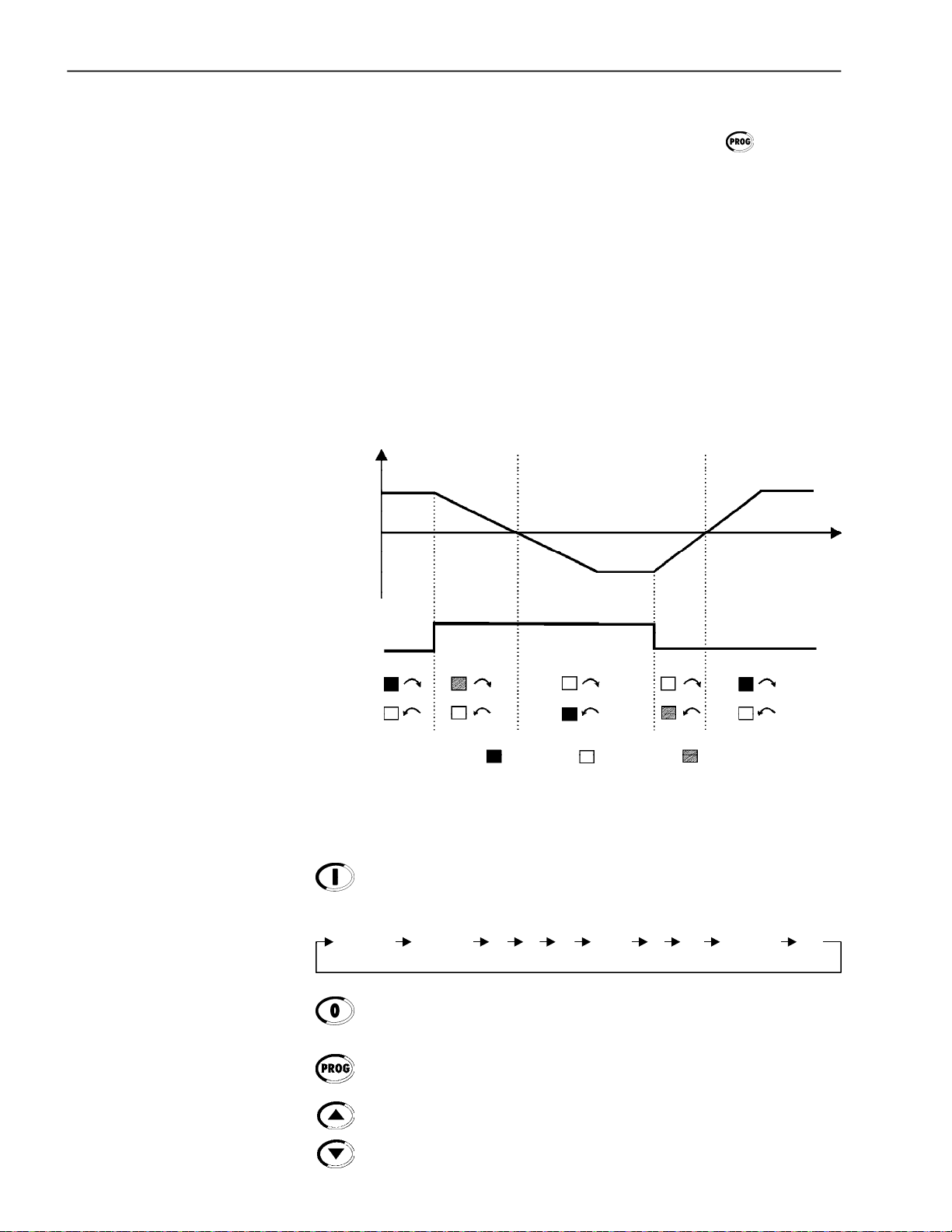
CHAPTER4- KEYPAD OPERATION
Functionsof the LCD Display:
The LCD Display shows the parameter number and its value
simultaneously, without the need of pressing the key. It also
providesa brief description of each parameter and also the units
(A,Hz,V,s,%,etc.)whennecessary.It also providesabriefdescription
of the fault code and inverter status.
Local and Remote Led Functions:
Soft-Starter in Local Mode:
GreenLedOn and Red LedOff.
Soft-Starter in Remote Mode:
GreenLedOff andRed Led On.
DirectionofRotation (FWD/REV)LED Functions:
Notimplemented in this Software Version
Speed
Forward
0
FWD / REVCommand(key)
ON
Figure 4.2 - Direction of Rotation (FWD / REV) LED´s
Reverse
OFF
FLASHING
Forward
Operation of the keypad:
Starts (Enable) the motor (start).
After starting, at each touch it commutates the fast access indication
(refer to item 4.2.2) on the display, as indicated below:
66
Current%
SSW
Current%
Motor
A
V
Input
Hz Status
SSW
Output
P.F.V
Torque%
Motor
Stops (Disables) the motor (stop).
Also resets the Soft-Starter after a fault has occurred.
Toggles the LED displaybetween the parameter numberand its value
(position/content).
Increasesthe number of the parameter or the valueof the parameter.
Decreasesthenumberoftheparameter or the valueof theparameter.
kW

CHAPTER4- KEYPAD OPERATION
Reversesthe directionofmotorrotationbetween Forward/Reverse.
TogglesbetweenLOCALor REMOTEmodes ofoperation.
Performs the JOG function when pressed. Any DIx programmed for
GeneralEnablemustbe closed (and theSSW-06 must be stopped)to
enableJOG function.
4.2 USE OF THE KEYPAD
4.2.1 Keypaduse for Soft-StarterSSW-06 Operation
The keypad is used for programming and operating the Soft-Starter
allowingthe followingfunctions:
Indication of the Soft-Starter SSW-06 status and main operation
variables;
Fault indications;
Viewingand programming ofthe setable parameters;
Soft-Starter SSW-06 operation (via keys , and ).
Al the functions related to the SSW-06 Soft-Starter operation (Start,
Stop, Increment, Decrement, FWD/REV,JOG, Local/Remotesituation
commutation) can be performed through the keypad. All keypad are
enabled when the Local Mode has been selected. All these functions
canbeexecutedindividuallythroughdigitalinputs.Forthis,allparameters
related to these functions and to the corresponding inputs must be
programmed.
Operation of the keypad:
When programmed (P220 = 2 or 3), it selects the command source,
changingbetween "Local” and “Remote”.
When programmed (P229 = 0 (key , “ Local” condition)
and/or P230 = 0 ( key , “Remote” condition)).
Starts themotor viaAcceleration Ramp. (motor acceleratesaccording
to acceleration ramp and load characteristics).
Stops themotor via DecelerationRamp.(motor deceleratesaccording
todeceleration rampand stops).
It resets the Soft-Starterafter a fault trip (always active).
Reversesthemotor directionofrotation.
Enabled when P220 = 2 (Keypad LOC), P229 = 0 (HMI Key), Local
Mode, P231 = 1 (By Contactor) or P231 = 2 (JOG Only).
Enabledwhen P220 = 3 (Keypad REM), P230 = 0 (HMI Key), Remote
Mode, P231 = 1 (By Contactor) or P231 = 2 (JOG Only).
When P231 = 1 (ByContactor), changesthemotordirectionofrotation
viacontactor, if thecontactorsareconnectedat the input power supply
and P277 = 4 (FWD/REV-K1)and P278 = 4 (FWD/REV-K2).
When P231 = 2 (JOG Only), changes the motor direction of rotation
onlyby the Jog function. Contactors are not required.
Enabledwhen P510 = 1 (Active).
When the Jog key is pressed, it accelerates the motor to the Jog
frequencyconforming tothe motordirection of rotation. When the Jog
key is released, the motor decelerates and stops.
Themotor mustbedisabledandtheSoft-Starter SSW-06must havea
GeneralEnable.
67

CHAPTER4- KEYPAD OPERATION
4.2.2 Keypad Display - Signalling Indications
Press
SSW Current
P001= 50.0%
Press
Output Power
P010= 22.9kW
Press
Press
Motor Current
P002= 100.0%
ParametersP001toP099areReadOnlyParameters.Thefirstparameter
tobedisplayedwhentheSoft-Starterispowered-up,canbeprogrammed
at P205.
The user is ableto visualizesome Read Only Parameters by pressing
the key.
Press Press
Press
Motor Current
P003= 42.5A
Press
Line Voltage
P004= 380V
Press
Line Frequency
P005= 60.0Hz
Press
Motor Torque
P00 9= 100.0%
Power Factor
P008= 0.89
Soft-Starter Status:
Output Voltage
P007= 379V
P205 Parameter to be displayed first
0 P001 (Soft-Starter current %In of the Soft-Starter)
1 P002 (Motor current %In of the Motor)
2 P003 (Motor current)
3 P004 (Line voltage)
4 P005 (Line Frequency)
5 P006 (Soft-Starter Status)
6 P007 (Output Voltage)
7 P008 (Power Factor)
8 P009 (Motor Torque % Tn of the Motor)
9 P010 (Output Power)
Table 4.1 - Parameter initially shown on the displays
Soft-Starter is "ready" to be enabled
SoftStarter
Ready
SSW Status
P006= Bypass
68
Soft-Starter with fault
Fault description
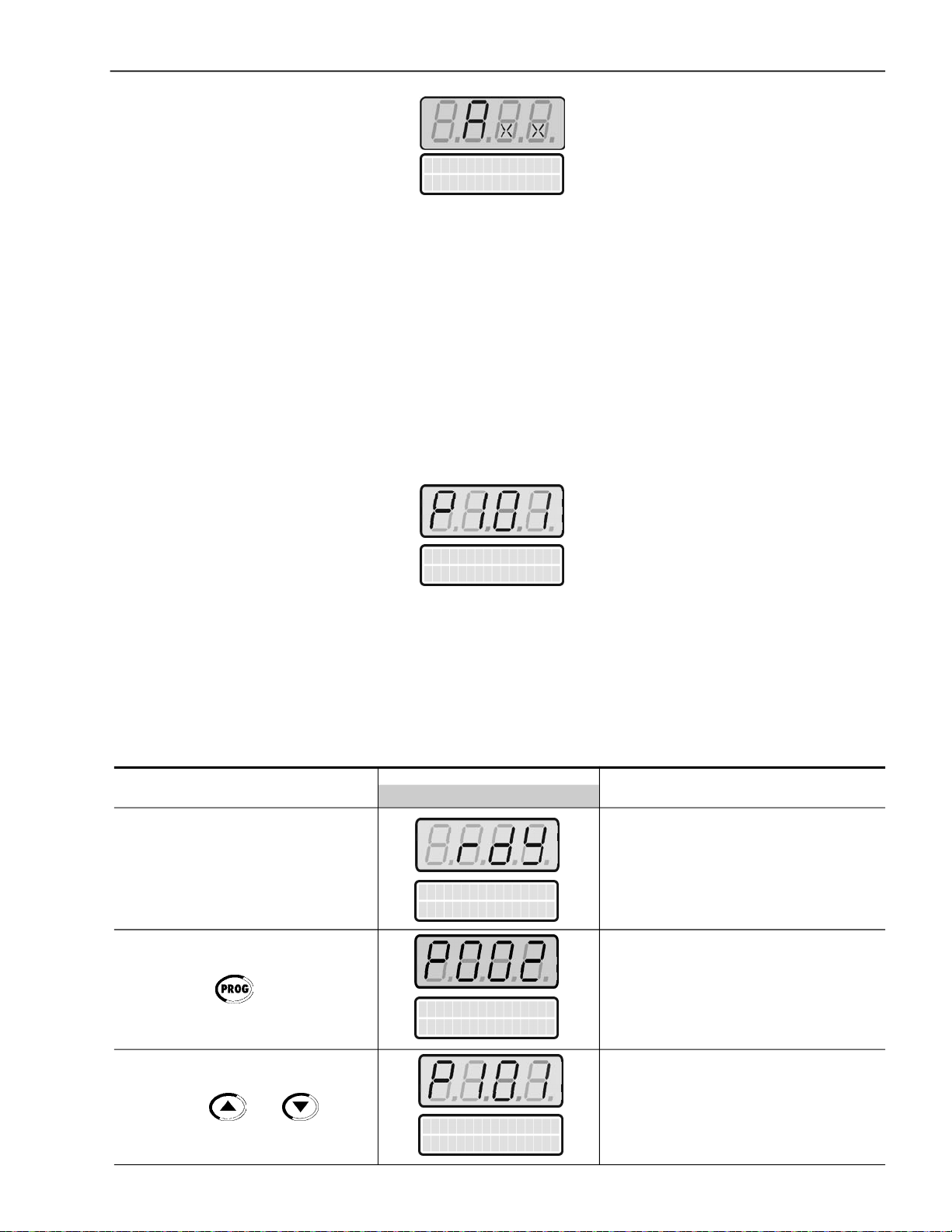
CHAPTER4- KEYPAD OPERATION
Soft-Starter withAlarm
Alarm description
Note:Thesestatesareshowed automaticallyonthedisplay;
theothersareintheparameterP006.Refertothechapter6.
7 Segment Display is flashing
The display flashes in the followingconditions:
Trying to change a parameter value whenit is not allowed;
Soft-Starterin Fault condition (see table 8.1).
4.2.3 Parameter viewingand programming
ACTION
All Soft-Starter settings are made through the parameters. The
parameters are shown on the display with the letter P followed by a
number:
Example(P101):
101=ParameterNumber
Init. Volt Start
P101=30%
Each parameter is associated with a numerical value (parameter
content), that corresponds to an option selected among the options
available for this parameter.
The values of the parameters define the Soft-Starterprogramming or
thevalue of a variable(e.g.current, frequency,voltage).ForSoft-Starter
programmingyoushouldchangetheparameter(s)content(s).
LEDDISPLAY
LCDDISPLAY
DESCRIPTION
Press the key
Use the keys and
SoftStarter
Ready
Motor Current
P002=0.0%
Selectthe desired parameter
Init. Volt Start
P101=30%
69
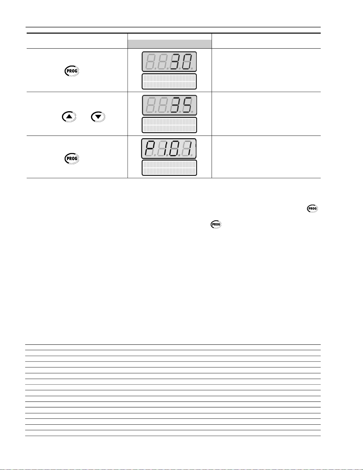
CHAPTER4- KEYPAD OPERATION
ACTION
Press the key
Use the keys and
Press the key
LEDDISPLAY
LCDDISPLAY
DESCRIPTION
Numeric value associated withthe
Init. Volt Start
P101=30%
Init. Volt Start
P101=35%
Init. Volt Start
P101=35%
parameter
Sets the new desired value.
(1) (2) (3)
(4)
(1) (4)
(1) For parameters that can be changed with the motor running, the
Soft-Starterwillusethenewvalueimmediatelyafterithas been set.
Forthe parameters thatcanbechanged onlywiththemotorstopped,
the Soft-Starterwill use this new set value only after the key
is pressed.
(2) By pressing the key after the reprogramming, the new
programmedvaluewillbesavedautomaticallyandwill remainstored
untilanew value is programmed.
(3) If the last value programmed in the parameter is not functionally
compatible with other parameter values already programmed, an
E24-ProgrammingError-will bedisplayed.Exampleofprogramming
error:
Programming twodigitalinputs(DIx)withthesame function.Refer
to Table4.2 for the list of programming errors that will generate an
E24 ProgrammingError.
(4) To allowthe reprogramming of anyparameter value it is necessary
tochangeparameterP000 tothepasswordvalue.Thefactorydefault
password value is 5. Otherwise you can only read the parameter
valuesandnotreprogramthem.
For more details see P000 description in Chapter 6.
E24 - Programming Error
Twoor more parameters between P266, P267, P268 equal to 1 (FWD/REV)
Twoor more parameters between P266, P267, P268 equal to 2 (LOC/REM)
(P202 = 2 and P520 = 1) if there is pump control with kick start
(P202 = 3 and P520 = 1) if there is torque control with kick start
(P150 = 1 and P500 = 3) if there is DC-Braking with Inside Delta
(P643 > P642) The reset value for the motor thermal protection alarm is higher then the alarm setting
(P950=1 and P089=0) The SoftPLC is enabled without a CCS6 that supports it
(P263=1 and P264=1 or P265=5) if there is Start/Stopfor DI1 and Stop 3 Wires for DI2 or DI3
(P263=1 and P264=4 or P265=4) if there is Start/Stop for DI1 and Start 3 Wires for DI2 or DI3
(P263=1 and P264=3 or P265=3) if there are more than one DI programmable to Start/Stop
(P263=2 and P264=4 or P265=4) if there are more than one DI programmable to Start 3 Wires
(P263=3 and P264=1 or P265=5) if there are more than one DI programmable to Stop 3 Wires
(P3090 and P951=1) if there is Fieldbus Communication Board with IOs Expansion Board
(P265=6 and P2310) if there is Emergency Start with FWD/REV
(P265=6 and P5000) if there is Emergency Start with any braking method
(P265=6 and P510=1) if there is Emergency Start with JOG function
Table 4.2 - Incompatibility between Parameters - E24
70

CHAPTER 5
START-UP
ThisChapterprovidesthefollowing information:
Howtocheckandpreparethe Soft-StarterSSW-06beforepower-up;
Howto power-upand check for proper operation;
Howtooperate the Soft-StarterSSW-06(SeeElectricalInstallation).
5.1 POWER-UP PREPARATION
The Soft-Starter SSW-06 shall be installed according to Chapter 3 InstallationandConnection.Ifthedriveprojectisdifferentfrom thetypical
recommended drives, the steps below may also be followed.
DANGER!
Disconnect theAC inputpower before making any connections.
1) Check all connections:
Check if the power, grounding and control connections are correct
andwelltightened.
2) Clean the inside of the Soft-Starter SSW-06:
Removeall shipping materialfrom the insideof theSoft-Starter
SSW-06 or cabinet.
3) Check the correct voltage selection:
Inmodels 255A to 820A,thefan supplyvoltageselectioniscorrect.
In models 950A to 1400A the single-phase supply voltage must be
checked to make sure it is adequate for the voltage of the fans.
4) Check the motor:
Check all motor connections and verify if their voltages, currents
andfrequencies match the Soft-Starter SSW-06 specifications.
5) Check the Soft-Starter SSW-06 motor connection type:
Checkif thestandardthree-wireconnectionshouldbeusedorifthe
Soft-Starter SSW-06 should be connected via inside delta of the
motor.For moredetails, referto Chapter 3.
6) Uncouple the load from the motor:
If the motor cannot be uncoupled, make sure that the direction of
rotation(FWD/REV) cannotcause damage to the machine.
7) Close the Soft-Starter SSW-06 and/or cabinet cover.
71
CHAPTER5- START-UP
5.2 INITIALPOWER-UP (requiredparametersettings)
After the Soft-Starter SSW-06 has been checked, AC power can be
applied:
1) Check the supply voltage:
Measurethelinevoltageandcheck if it is withinthespecifiedrange
(Nominal Voltage-15% to +10%).
2) Power-up the Electronics Supply.
NOTE!
Always energize the electronics supply before energizing the power
and execute all adjustments/settings described in this item.
3) Check if the power-up has been successful
When the Soft-Starter SSW-06 is powered up for the first time or
whenthefactorydefaultparameter valuesare loaded (P204=5),a
start-up routineis run.
This routine requests the user to program some basic parameters
toensureproperSoft-StarterSSW-06 operationandmotoroperation.
This routine sequence changes according to the selected type of
control.Formore details about the controltypetobeselected,refer
to Parameter P202 in Chapter 6.
The parameterization sequence for each control type is show in
figure5.1.
ATTENTION!
Forcorrectprogrammingoftheprotectionparameters,please consider
the catalog data and the motor nameplate data of the used motor.
To protect the motor against overloads during the start process and
during operation, program the thermal class of the motor. For more
details about programming of the Thermal Class, see description of
ParameterP640 in Chapter6.
Inthisparametersettingsequenceonlythemainparametersforlearning
about the Soft-Starter SSW-06 operation are shown. Please program
all necessaryparameters for correct operation of the Soft-Starterand
motor protection, before operating it atnominal operationconditions.
4) Close the input circuit-breaker.
72

P201
P150
P202
CHAPTER5- START-UP
Voltage
Ramp
P101
P102
P400
P401
P406
P640
Current
Limit
P102
P110
P400
P401
P406
P640
Pump
Control
P130
P101
P102
P103
P104
P105
P400
P401
P610
P611
P620
Constant
Constant
P126
Torque
Control
P102
P120
Linear
P121P121
P122
P104
P125
Linear
P126
Quadratic
P121
P122
P123
P124
Quadratic
P126
Current
Ramp
P102
P110
P111
P112
P400
P401
P406
P640
P406
P640
Figure 5.1 - Parameter sequence during initial power-up
P127
P400
P401
P402
P404
P405
P406
P640
P127
P128
73
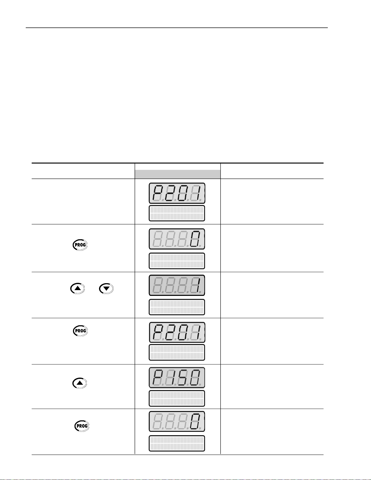
CHAPTER5- START-UP
Shownbelowis a parameterprogrammingexample requested by this
routine.
Example:
Soft-StarterSSW-06
SSW060130T2257PSZ
Motor
High EfficiencyPlus Three-Phase Electric Motor- 4 Poles - 60Hz
Power:75 HP
Frame size: 225S/M
Speed:1770rpm
Nominal current at 380V: 101A
ServiceFactor:1.15
Start mode
Start-up byvoltageramp.
ACTION
After Power-up, the Display shows
thefollowingmessage
Press the key to enter the
programmingmode
Use the keys and to
selectthe language
Press the key to save the
selected option and exit the
programmingmode
LEDDISPLAY
LCDDISPLAY
Language
P201 = Portugues
Language
P20 1 = Portugues
Language
P20 1 = English
Language
P20 1 = English
DESCRIPTION
LanguageSelection:
0=Português
1=English
2=Español
3=Deutsch
Entertheprogrammingmode.
Selectedlanguage:English
Exitthe programmingmode.
Press the key to go to the
nextparameter
Press the key to enter the
programmingmode
74
Delta Inside
P150=Inactive
Delta Inside
P150=Inactive
Soft-Starter Connection Typetothe
motor:
0=Inactive=standard 3 wires
1=Active = Delta inside 6 wires
Entertheprogrammingmode

CHAPTER5- START-UP
ACTION
Use the keys and for
programmingSoft-Starterconnection
type to motor
Press the key to save the
selected option and exit the
programmingmode
Press the key to go to the next
parameter
Press the Key to enter the
programmingmode
LEDDISPLAY
LCDDISPLAY
Delta Inside
P150=Inactive
Delta Inside
P150=Inactive
Type of Control
P202= Volt.Ramp.
Type of Control
P202= Volt.Ramp.
DESCRIPTION
Soft-Starter connection type to motor:
standard3 wires
(Maintain the existingvalue)
Exitthe programming mode
Selection of the start control type:
0=Voltageramp
1=CurrentLimit
2=PumpControl
3=TorqueControl
4=CurrentRamp
Entertheprogrammingmode.
Use the keys and to
select the start control type
Press the key to save the
selected option and exit the
programmingmode
Press the key to go to the next
parameter
Press the key to enter
programmingmode
Selected start control type:
Voltageramp
(Maintain the existingvalue)
Type of Control
P202= Volt.Ramp.
Exitthe programming mode
Type of Control
P202= Volt.Ramp.
Initialstartvoltage by voltage ramp:
(25to90)%Un
Init. Volt Start
P101=30%
Entertheprogrammingmode.
Init. Volt Start
P101=30%
75

CHAPTER5- START-UP
ACTION
Use the keys and to
select the initial start voltage
Press the key to save the
selected option and exit the
programmingmode
Press the key to go to the next
parameter
Press the key to enter the
programmingmode
LEDDISPLAY
LCDDISPLAY
Init. Volt Start
P101=35%
Init. Volt Start
P101=35%
Start Time Ramp
P102=20s
Start Time Ramp
P102=20s
DESCRIPTION
Initialselectedvoltage:
35%Un
(accordingto loadrequirements)
Exitthe programming mode
VoltageRamp Time:
(1 to 999)s
Entertheprogrammingmode.
Use the keys and to select
the ramp time for the startvoltage
Press the key to save the
selected option and exit the
programmingmode
Press the key to go to the next
parameter
Press the key to enter the
programmingmode
Use the keys and to
select the nominalmotor voltage
Start Time Ramp
P102=15s
Start Time Ramp
P102=15s
Nominal Motor Volt
P400=380V
Nominal Motor Volt
P400=380V
Nominal Motor Volt
P400=380V
Selected ramp time for the start
voltage: 15s
(accordingto loadrequirements)
Exitthe programming mode
Nominalmotorvoltage(Un):
(0 to 999)V
Entertheprogrammingmode.
Selectednominalmotorvoltage:
380V
(accordingto the motor data)
76

CHAPTER5- START-UP
ACTION
Press the key to save the
selected option and exit the
programmingmode
Press the key to go to the next
parameter
Press the Key to enter the
programmingmode
Use the keys and to
select the nominal motor current
LEDDISPLAY
LCDDISPLAY
Nominal Motor Volt
P400=380V
Nominal Motor Cur.
P401=20.0A
Nominal Motor Cur.
P401=20.0A
Nominal Motor Cur.
P401=101.0A
DESCRIPTION
Exitthe programming mode
Nominal motor current(In):
(0to 1500)A
Entertheprogrammingmode.
Selectednominalmotor current:
101A
(accordingto the motor data)
Press the key to save the
selected option and exit the
programmingmode
Press the key to go to the next
parameter
Press the Key to enter the
programmingmode
Use the keys and to
select the motor Service Factor
Nominal Motor Cur.
P401=101.0A
Service Factor
P406=1.00
Service Factor
P406=1.00
Service Factor
P406=1.15
Exitprogrammingmode
Motor Service Factor (S.F.):
0.00 to 1.50
Entertheprogrammingmode.
SelectedmotorServicefactor:
1.15
(accordingto the motor data)
Press the key to save the
selected option and exit the
programmingmode
Exitprogrammingmode
Service Factor
P406=1.15
77

CHAPTER5- START-UP
ACTION
Press the key to go to the next
parameter
Press the key to enter the
programmingmode
Use the keys and to
select the thermal motor protection
class
LEDDISPLAY
LCDDISPLAY
Ther.Prot.Class
P640=Class 30
Ther.Prot.Class
P640=Class 30
Ther.Prot.Class
P640=Class 30
DESCRIPTION
Thermalmotor ProtectionClass:
0=Inactive
1= Class 5
2= Class 10
3= Class 15
4= Class 20
5= Class 25
6= Class 30
7= Class 35
8= Class 40
9= Class 45
Entertheprogrammingmode.
Thermalmotor protectionclass:
6= Class 30
(According to the motor data)
Press the key to save the
selected option and exit the
programmingmode
Press the key to go to the next
parameter
Exitthe programming mode
Ther.Prot.Class
P640=Class 30
Soft-Starter is reset
Soft-Starter is readyfor operation
Soft Starter
ready
Open the inputcircuit-breaker to disconnect the Soft-StarterSSW-06.
NOTE!
Repeatthefirstpower-up process:
Ifyouwant torepeatthefirstpower-uproutine, set parameter P204 = 5
(it loads the factory standard default parameters), then follow the first
power-uproutine;
Thefirstpower-up routine,asdescribed above,automaticallysets some
parameters.For more details, refer to Chapter6.
78

CHAPTER5- START-UP
5.3 START-UP
This Section describes the start-up procedure when operating via the
Keypad.Five types of control will be considered:
Start-up by Voltage Ramp:
Thestart byvoltage rampisthemostusedmethod anditsprogramming
and parameter setting is very easy to do. The Soft-Starter SSW-06
appliesthe voltage to the motorwithout any feedback of the voltage or
current applied to the motor.
Start-up by Current Limit:
Themaximum programmed current level is maintainedduringstart-up
anditissetaccordingtotheapplicationrequirements.Thisprogramming
is very easy.
Start-up by Current Ramp:
Themaximum currentlevelis alsolimitedduringthestart-up, however
higher or lower start-up current limits can be set.
Start-up by Pump Control:
Optimized control method, providing the required torque to start/stop
hydrauliccentrifugal pumps smoothly.
Start-up by Torque Control:
TheSoft-StarterSSW-06isfittedwithatorquecontrolalgorithmof high
performanceand is totallyflexibletomeet any applicationrequirement
during the motor start or stop and its coupled load.
Themethodallows atorquecontrolwith1settingpoint,a torquecontrol
with 2 setting points and a torque control with 3 setting points.
NOTE!
Every time the content of the Parameter P202 is changed, the SoftStarterwillexecuteasetting sequenceroutineaccordingtotheselected
control type.
For more details, refer to Parameter P202 in Chapter 6 and 7.
Thefollowing sequence isvalidforDrive 1 (seeitem3.3.1).TheSSW-06
Soft-Starter must already be installed and the electronics, fans and
power must already be energized, according to chapter 3, with the
setting sequence of the initial Start-up complete, as described in the
Item 5.2.
5.3.1 Start-up: Operation viaKeypadType of control: Voltage Ramp
ACTION
Power-up theSoft-Starter
Press the key . Press the key
to find P000. Also the key
may be used to findParameter P000
LEDDISPLAY
LCDDISPLAY
Soft Starter
ready
Parameter Access
P000=0
Soft-Starter is readyto be operated
It enables the access for changing
parameters. Withsetting according to
Factory Default [P200 = 1 (Password is
active)], you must set P000 = 5 for
changingtheparametercontent.
DESCRIPTION
79

CHAPTER5- START-UP
ACTION
Press the key to enter the
programmingmode
Use the Keys and to
programthePassword value
Press the key to save the
selected option and exit the
programmingmode
Press the key to find P202.
Also the key may be used to
findParameterP202
LEDDISPLAY
LCDDISPLAY
Parameter Access
P000=0
Parameter Access
P000=5
Parameter Access
P000=5
Type of Control
P202=Volt. Ramp.
DESCRIPTION
EntertheProgrammingMode
Passwordvalue
(FactoryDefault)
Exitthe programming mode
ThisParameterdefinestheTypeof
Control
0=VoltageRamp
1=CurrentLimit
2=PumpControl
3=TorqueControl
4=CurrentRamp
Press the Key to enter the
programmingmode
Use the keys and to
select the correct valueof the Control
Type
Press the key to save the
selected option and exit the
programmingmode
Press the key and maintain it
depressedto find P003
EntertheProgrammingMode
Type of Control
P202=Volt. Ramp.
Type of Control selectedfor the
Start-up: VoltageRamp
(maintain theexistingvalue)
Type of Control
P202=Volt. Ramp.
Exitthe programming mode
Type of Control
P202=Volt. Ramp.
MotorCurrent(A)
Motor Current
P003=0A
80
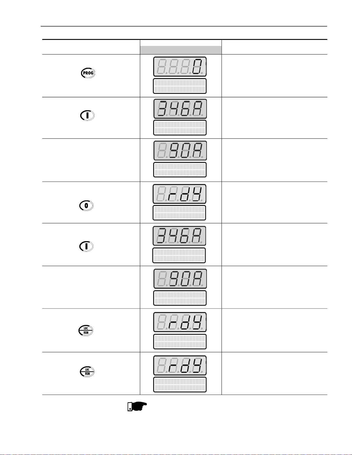
CHAPTER5- START-UP
Press the key
Press the key
Press the key
ACTION
LEDDISPLAY
LCDDISPLAY
Motor Current
P003=0A
Motor Current
P003=346 A
Motor Current
P003=90A
SoftStarter
ready
DESCRIPTION
This is only a Read Parameter
Motoraccelerates and ahigh valueof
currentis reached.
Then the current decreases down to a
valuerequiredbytheload.
Motor decelerates until stopping by
coast to rest. Time to stop depends on
loadinertia and friction.
Press the key
Press the key
Press the key again
Motor Current
P003=346 A
Motoraccelerates and ahigh valueof
currentis reached.
Then the current decreases up to a
Motor Current
P003=90A
valuerequiredbytheload.
Soft-Starter is nowcontrolledvia
terminals(REMOTE).Motor
decelerates till stopping by the load
SoftStarter
ready
inertia.
Soft-Starter is controlledagainvia
keypad(LOCAL).Motorremains
SoftStarter
ready
stopped.
NOTES!
Setting hints and suggestions for all types of controls and their uses
can be found in Chapter 7.
Forstart-up through voltage ramp refer to Item 7.1.1.
81

CHAPTER 6
DETAILED PARAMETER DESCRIPTION
This Chapter describes in detail all Soft-StarterSSW-06 parameters. In order
tosimplifytheexplanation,theparametershavebeengroupedbycharacteristics
andfunctions:
Read Only Parameters Variables that can only be viewed on the display but
not changed by the user.
RegulationParameters Programmable values used by the Soft-Starter
SSW-06 functions.
Configuration Parameters These Parameters define the Soft-Starter
SSW-06 characteristics, the functions to be executed,
aswellas theinput/output functionsof the control board.
MotorParameters Motor data that are indicated on the motor nameplate.
SpecialFunction Parameters Here are the parameters related to special functions.
Protection Parameters Here are the parameters related to actuation levels
and actuation time of the motor protection.
Symbols and definitions used in the text below:
(1) Indicates that the parameter can only be changed when the Soft-Starter
SSW-06isdisabled(motorstopped).
(2) Parameters not changedwhenprogrammed to FactoryDefault(P204=5).
6.1 ACCESS AND READ ONLYPARAMETERS - P000 to P099
Range
[FactorySetting]
Parameter Unit Description/ Notes
P000 0 to 999
ParameterAccess [0]
PasswordValue -
Setting
This parameter opens the access to change the parameter values.
Whenvalues aresetaccordingtoFactoryDefault[P200=1(Password
is active)] set P000 = 5 to change parameter values, and the
Password value is equal to 5.
By programming P000 with the password that releases access to
change parameter contents, plus 1 (Password + 1), you will obtain
accessonlytotheparameters withcontentsdifferentfromthefactory
setting.
Tochangethepasswordtoanyothervalue(password 1),proceedas
follows:
(1) SetP000=5 (current password)and P200= 0 (password inactive).
(2) Press the key .
(3) ChangeP200to 1 (passwordactive).
82
(4) Press the key again: display shows P000.
(5) Press the key again: display shows 5 (last password).
(6) Use the keys and to change to the desired password
value(password1).
(7) Press the key : display shows P000. From this moment on,
the new password becomes active. Thus, to change parameter
content P000 must be set to the new password. (Password 1).
CHAPTER6 - DETAILED PARAMETER DESCRIPTION
Range
[FactorySetting]
Parameter Unit Description/ Notes
P001 0 to 999.9
Soft-StarterSSW-06 [ - ]
Current 0.1%
P002 0 to 999.9
MotorCurrent [ - ]
0.1%
P003 0 to 9999.9
MotorCurrent [ - ]
0.1A
Indicates Soft-Starter SSW-06 output current as percentage of the
nominal current of theSoft-Starter(%In of the SSW-06) .
Precision of ± 2% for the full scale. (The full scale is 5 x ln of the
SSW-06).
NOTE!
Whenthemotorconnectionisinsidedelta(P150=1),theindication
of the current value will already be multipliedby 1.73.
Indicates Soft-Starter SSW-06Output Current as percentageof the
nominalmotor current(%In of the motor).
Precision of ± 2% for the full scale. (The full scale is 5 x ln of the
SSW-06).
NOTE!
Whenthemotorconnectionisinsidedelta(P150=1),theindication
of the current value will already be multipliedby 1.73.
Indicates the Soft-StarterSSW-06 output current in Amperes (A).
Precision of ± 2% for the full scale. (The full scale is 5 x ln of the
SSW-06).
P004 0 to 999
LineVoltage [ - ]
1V
P005 0 to 99.9
LineFrequency [ - ]
0.1Hz
NOTE!
Whenthemotorconnectionisinsidedelta(P150=1),theindication
of the current value will already be multipliedby 1.73.
Indicates the average True rms voltage of the three input phases in
Volts (V).
Accuracy: ± 2V.
NOTE!
Thevoltage willonly beindicated when it reachesa value greater
than15V.Belowthis value,only0 (zero)will be indicated.
Indicates the line frequency in Hertz (Hz).
Precision of ± 5% of the nominal frequency of the supply network.
NOTE!
Onlyindicatesnetwork frequencywhenthereisavoltagegreater
than 20V rms in the power supply (R/ 1L1, S/ 3L2 and T/5L3).
83
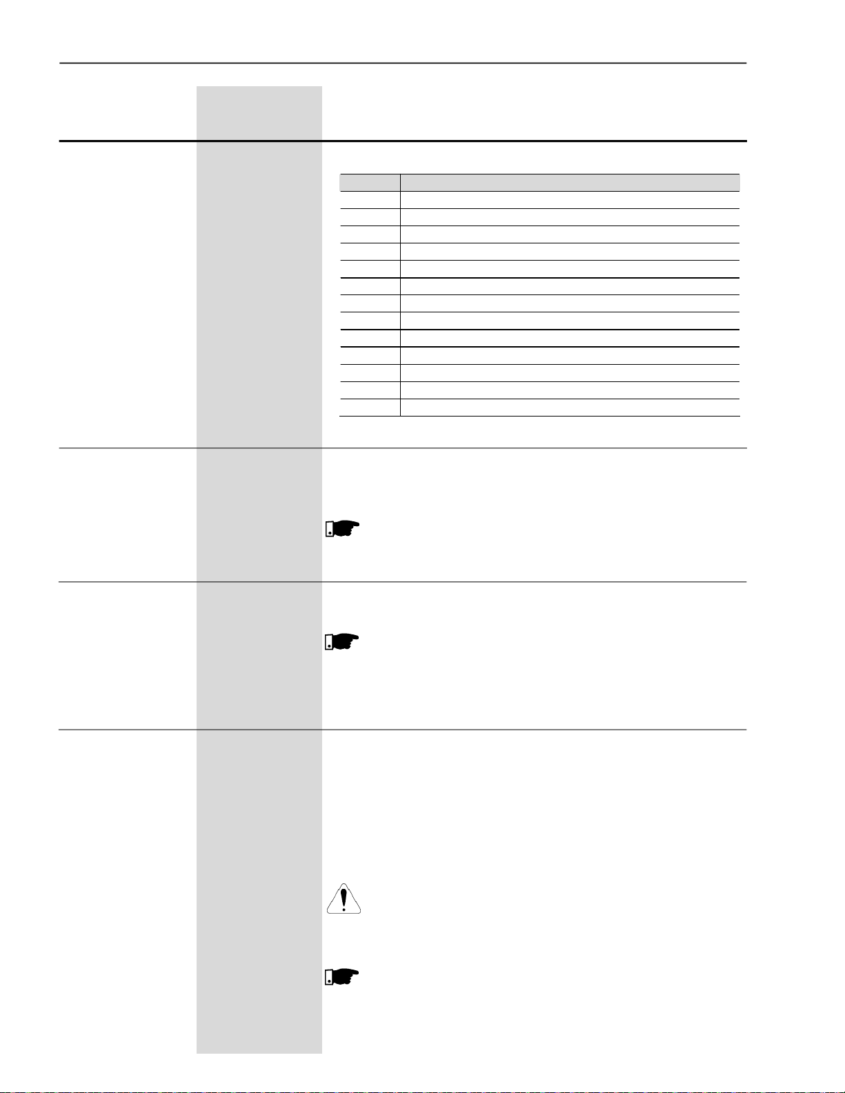
CHAPTER6 - DETAILED PARAMETER DESCRIPTION
Range
[FactorySetting]
Parameter Unit Description/Notes
P006 0 to 12
Indicates the actual Soft-Starter SSW-06 status:
Soft-StarterSSW-06 [ - ]
Status 1
P006 Description of the Soft-Starter status
0 Ready to start the motor
1 Performing the initial test of the line and of the motor
2 With a fault
3 During acceleration ramp
4 At full voltage
5 With the By-pass contactor activated
6 Reserved
7 During deceleration ramp
8 Performing braking
9 Performing reversion of the speed direction
10 During Jog
11 During the P630 time delay
12 With the General Enable deactivated
Table 6.1 - Soft-Starter status
P007 0 to 999
Soft-StarterSSW-06 [ - ]
OutputVoltage 1V
P008 0 to 1.00
PowerFactor [ - ]
-
P009 0 to 999.9
Motor Torque [ - ]
0,1%
Indicates the averageTruerms voltageof the threeoutputphases of
the Soft-StarterSSW-06 in Volts (V).
Accuracy: ± 2V.
NOTE!
Thevoltage willonly be indicatedwhenit reachesavaluegreater
than 15V. Below this value, only 0 (zero) will be indicated.
Indicatesmotorpowerfactor.
Accuracy: ± 5%.
NOTE!
Themotor power factorwillonlybeindicatedwhen the currentis
greater than 20% of the nominal current of the SSW-06.
0 (Zero) will be indicated if the current is below 20% of the
SSW-06 nominal current.
Indicates the motor torque in percent of the nominal motor torque
(% Tn of the Motor).
The Soft-Starter SSW-06 is fitted witha software for estimating the
motor torque by using the same principles contained in WEG
FrequencyInverters.
This high technology software enables indicating the motor torque
verycloseto the effective present torque.
Accuracy of ± 10% Tn of the Motor.
84
ATTENTION!
Information related to the nominal torque of the motor and
maximum starting torque of the motor can be found in the
manufacturer’scatalogue.
NOTE!
Forthecorrect torquetobeindicated, inP009,alltheparameters
related to the motor, P400 to P406, must be correctly
programmed according to the data informed on the motor
nameplate.
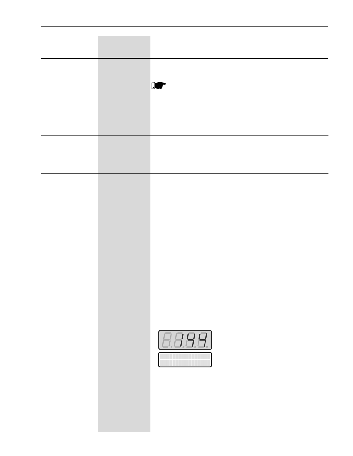
CHAPTER6 - DETAILED PARAMETER DESCRIPTION
Range
[FactorySetting]
Parameter Unit Description/ Notes
P010 0 to 6553.5
OutputPower [ - ]
0.1kW
P011 0 to 6553.5
ApparentOutput [ - ]
Power 0.1kVA
P012 LCD=1,0
DI1 to DI6 Status LED=0to 255
[ - ]
-
Indicates the active power as average of the three output phases of
the Soft-StarterSSW-06 in kilo Watts (kW).
NOTE!
Theoutputpowerwillonlybeindicatedwhenthecurrent is greater
than20% of theSSW-06 nominalcurrent.
0 (Zero) will be indicated if the current is lower than 20% of the
SSW-06 nominal current.
Indicates the apparent power as average of the three output phases
of the Soft-StarterSSW-06 in kilo VoltAmperes (kVA).
Indicateson the keypadLCD displaythe status of the6 digitalinputs
ofthecontrolboard(DI1...DI6).Number1standsforActiveandNumber
0for Inactive,in the followingorder: DI1, DI2,..., DI5, DI6.
TheLED Display shows a decimal value correspondingtothe status
of the 6 digital inputs, where the status of each input is considered
one bit in the specified sequence:
Inactive=0
Active=1
DI1 status is the most significant bit.
The 2 least significant bits are always ‘’0'’.
Example:
Dl1 = Active (+24V); Dl4 =Active (+24V);
Dl2= Inactive (0V); Dl5= Inactive (0V);
Dl3= Inactive (0V); Dl6= Inactive (0V).
It is equivalent to the bit sequence:
10010000
Which corresponds tothe decimal number 144.
The least significant bits are not displayed.
The keypad displays will be as follows:
DI1...DI6 Status
P012=100100
85
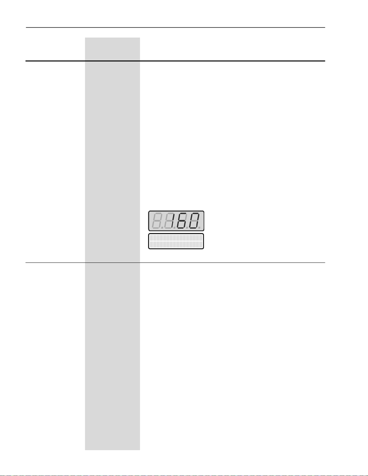
CHAPTER6 - DETAILED PARAMETER DESCRIPTION
Range
[FactorySetting]
Parameter Unit Description / Notes
P013 LCD=1,0
RL1 to RL3 Status LED=0to 255
[ - ]
-
Indicatesonthe keypadLCD displaythe status of the 3 relayoutputs
ofthecontrolboard.Number1standsforActiveand 0 for Inactive,in
thefollowing order:
RL1,RL2,RL3.
The keypad LED display shows the decimal value that corresponds
to the status of the 3 digital outputs, where the status of each output
is considered one bit in the specified sequence:
Inactive=0
Active=1
RL1 status is the most significant bit.
The 5 least significant bits are always "0".
Example:
RL1=Active;RL2=Inactive;RL3=Active
This is equivalent to the binarysequence:
10100000
Which corresponds tothe decimal number 160.
The least significant bits are not displayed.
The Keypad displays will be:
P014 0 to 99
Last Fault [ - ]
-
P015 0 to 99
SecondPrevious [ - ]
Fault -
P016 0 to 99
ThirdPrevious [ - ]
Fault -
P017 0 to 99
Fourth Previous [ - ]
Fault -
P018 0 to 99
FifthPrevious [ - ]
Fault -
P019 0 to 99
SixthPrevious [ - ]
Fault -
RL1...RL3 Status
P013=101
Indicate the code of the last previous Faults.
FaultSequence:
Exy P014 P015 P016 P017 P018 P019
86

CHAPTER6 - DETAILED PARAMETER DESCRIPTION
Range
[FactorySetting]
Parameter Unit Description / Notes
P020 0 to 99
CurrentFault [ - ]
-
It indicates if any fault is active.
NOTE!
Erros related to communication (E28, E29 and E30) are not
indicated in P020.
P021 0 to 99
CurrentAlarm [ - ]
-
P023 X.XX
Software Version [ - ]
-
P027 0 to 10.000
Analog OutputAO1 [ - ]
Value 0.001V
P028 0 to 20.000
Analog OutputAO2 or
Value 4.000to 20.000
[ - ]
0.001mA
P030 0 to 9999.9
Currentof Phase R [ - ]
0.1A
P031 0 to 9999.9
Currentof PhaseS [ - ]
0.1A
It indicates if any alarm is active.
Indicatesthesoftwareversioncontainedinthemicrocontrollermemory
of the controlboard.
It indicates the analog outputAO1 value directly in “mV”.
It indicates the analog outputAO2 value directly in “mA”.
Accuracy: ± 2% for full scale (full scale is 5 x In of the SSW-06).
NOTE!
When the insidedeltaconnection ofthemotor is used(P150=1),
the indication of the current value will already be multiplied by
1.73.
P032 0 to 9999.9
CurrentofPhaseT [ - ]
0.1A
P033 0 to 999
LineVoltage- R-S [ - ]
1V
P034 0 to 999
LineVoltage - S-T [ - ]
1V
P035 0 to 999
LineVoltage - T-R [ - ]
1V
Accuracy: ± 2V.
NOTE!
Thevoltagewillonlybeindicated whenitreachesavaluegreater
than 15V. Below this value, only 0 (zero) will be indicated.
87

CHAPTER6 - DETAILED PARAMETER DESCRIPTION
Range
[FactorySetting]
Parameter Unit Description / Notes
P042 0to 65535
TimePowered [ - ]
1h
Indicates the totalnumber ofhoursthatthe Soft-Starterwaspowered.
This value remains stored even when the Soft-Starter is switched
OFF.
NOTE!
The indication on the LED display was modified and is different
from the previoussoftwareversions,followingnowthe standard
described in the item 4.1.
P043 0 to 6553.5
TimeEnabled [ - ]
0.1h
P044 0 to 999.9
kWh Counter [ - ]
1kWh
P045 0 to 9999
MWhCounter [ - ]
1MWh
P047 0 to 9999.9
Maximum Starting [ - ]
Current 0.1A
Indicates the total number of hours that the Soft-Starterhas run.
Thisvalue remainsstored even when theSoft-Starter is turned OFF.
Indicates up to 6553,5hours, rolls over to 0000.
If P204 is set to 3, P043 is reset to zero.
Indicates the energy consumed by the motor,in kWh.
Indicates up to 999.9kWh, then it returns to zero.
If P204 is set to 3, P044 is reset to zero.
Thisvalue remains storedeven when the Soft-Starteris turned OFF.
Indicates the energy consumed by the motor, in MWh.
Indicates up to 9999MWh, then it returns to zero.
If P204 is set to 3, P045 is reset to zero.
ThisvalueremainsstoredevenwhentheSoft-StarteristurnedOFF.
It stores the value of the maximum current during the start.
The value of P047 is reset at the beginning of each start.
If P204 is set to 3, P047 is reset to zero.
This value is not kept when the Soft-Starter is turned OFF.
Itdoes not record currents of the JOG function.
P048 0 to 9999.9
AverageStarting [ - ]
Current 0.1A
P049 0 to 999
RealStarting Time [ - ]
1s
88
Itstores thevalue of the averagecurrent during the start.
The value of P048 is reset at the beginning of each start.
P204 is set to 3, P048 is reset to zero.
This value is not kept when the Soft-Starter is turned OFF.
Itdoes not record currents of the JOG function.
It stores the real starting time.
The real starting time is the time required for the motor to reach its
nominalspeed.
The real starting time depends on the starting parameters settings
and on the load conditions. The time set in P102, even for voltage
ramp, is not the real starting time.Amotorwithoutload, for instance,

CHAPTER6 - DETAILED PARAMETER DESCRIPTION
Range
[FactorySetting]
Parameter Unit Description / Notes
canreachitsnominalspeedwithlowvoltages.Andthetime adjusted
in P102 is the time in which the Soft-Starterapplies 100% of the line
voltagetothe motor.
The valueof P049 is reset at the beginningof each start.
If P204 is set to 3, P049 is reset to zero.
This value is not kept when the Soft-Starter is turned OFF.
P050 0 to 250
Motor Thermal [ - ]
Protection Status 1%
P053
MaximumCurrent at
FullVoltage
P054
Maximum Line Voltage
with the Motor
Running
0 to 9999.9
[ - ]
0.1A
0 to 999
[ - ]
1V
Indicationof thestate of motorthermalprotectiononascale of 0%to
250%. 250 being the thermal protection functioning point of the motor,indicatinganerror.
The value indicated in this parameter depends on the motor working
condition and how long it has been in this condition, for example:
stopped, starting or in full operation. The value also depends on the
selectedthermal class,thenominal powerandtheservicefactorof the
motor.
Avalue of approximately 160 canbe readif themotor is operating in
full load for over 2 hours with a current equal to the nominal current
times the service factor (In x S.F. @ 2h).
If P204 is set to 3, P050 is reset to zero.
Thisvalue remains storedeven when the Soft-Starter is turned OFF.
It stores the value of the maximum current during the period the
motor is working at full voltage or with the By-pass activated.
If P204 is set to 4, P053 is reset to zero.
ThisvalueremainsstoredevenwhentheSoft-Starteris turnedOFF.
It stores the highest line voltage value with the motor in operation.
If P204 is set to 4, P054 is reset to zero.
ThisvalueremainsstoredevenwhentheSoft-Starteris turnedOFF.
P055
MinimumLine Voltage
with the Motor
Running
P056
MaximumLine
Frequencywith the
MotorRunning
0 to 999
[ - ]
1V
0 to 99
[ - ]
1Hz
It stores the lowest linevoltage valuewith the motor in operation.
If P204 is set to 4, P055 is reset to zero.
Thisvalue remains storedeven when the Soft-Starter is turned OFF.
Itstores thehighestline frequency value with the motor inoperation.
If P204 is set to 4, P056 is reset to zero.
Thisvalue remains storedeven when the Soft-Starter is turned OFF.
89

CHAPTER6 - DETAILED PARAMETER DESCRIPTION
Range
[FactorySetting]
Parameter Unit Description / Notes
P057
MinimumLine
Frequencywith the
0 to 99
[ - ]
1Hz
It stores the lowest line frequency value with the motor in operation.
If P204 is set to 4, P057 is reset to zero.
Thisvalue remains storedevenwhen the Soft-Starter is turnedOFF.
MotorRunning
P058
MaximumNumberof
Starts perHour
P059
TotalNumber ofStarts
P060, P063, P066,
P069, P072 and P075
Current at the Fault
Trip
P061, P064, P067,
P070, P073 and P076
Voltage at the Fault
Trip
P062, P065, P068,
P071, P074 and P077
SSW Status at the
FaultTrip
0 to 32
[ - ]
1
0 to 65535
[ - ]
1
0 to 9999.9
[ - ]
0.1A
0 to 999
[ - ]
0.1A
0 to 12
[ - ]
1
It stores the maximum number of starts per hour.
It has the capacity of storing one start every 112.5 s, totalizing a
maximum of 32 starts in one hour. If two or more starts occur during
this time period of 112.5 s, onlyone is recorded.
If P204 is set to 4, P058 is reset to zero.
Thisvalue remains storedevenwhen the Soft-Starter is turnedOFF.
It stores the total number of starts executed by the Soft-Starter.
In order to be considered a start, the motor must initiate the starting
after the initial test, i.e., the line and motor connections must be
correct.
Thisvalue remains storedevenwhen the Soft-Starter is turnedOFF.
P060, P063, P066, P069, P072 and P075 stores the motor current
value at the moment of the fault trip, according to the table 6.2.
P061, P064, P067, P070, P073 and P076 stores the motor voltage
value at the moment of the fault trip, according to the table 6.2.
P062, P065, P068, P071, P074 and P077 stores the Soft-Starter
statusat the moment of the fault trip, accordingtothe table 6.2.The
Soft-Starter status are described in the parameter P006.
ThisvalueremainsstoredevenwhentheSoft-StarteristurnedOFF.
Sequence
of Faults
P014
(Last)
P015
(2nd)
P016
(3rd)
P017
(4th)
P018
(5th)
P019
(6th)
Related
Parameters
P060 Motor current at the last fault trip
P061 Line voltage at the last fault trip
P062 Soft-Starter status at the last fault trip
P063 Motor current at the second fault trip
P064 Line voltage at the second fault trip
P065 Soft-Starter status at the second fault trip
P066 Motor current at the third fault trip
P067 Line voltage at the third fault trip
P068 Soft-Starter status at the third fault trip
P069 Motor current at the fourth fault trip
P070 Line voltage at the fourth fault trip
P071 Soft-Starter status at the fourth fault trip
P072 Motor current at the fifth fault trip
P073 Line voltage at the fifth fault trip
P074 Soft-Starter status at the fifth fault trip
P075 Motor current at the sixth fault trip
P076 Line voltage at the sixth fault trip
P077 Soft-Starter status at the sixth fault trip
Parameter Descriptions
90
Table 6.2 - Sequence of faults and their respective diagnostics

CHAPTER6 - DETAILED PARAMETER DESCRIPTION
Range
[FactorySetting]
Parameter Unit Description/ Notes
P085 0 to 3
Fieldbus [ - ]
Communication BoardStatus
P088 0 to 4
SoftPLCStatus [ - ]
1
P085 Description
0 Off
1 Board inactive
2 Board active and Offline
3 Board active and Online
Table 6.3 - Fieldbus communication board status
Indicates the status of the Fieldbus communication board.
Standard is disabled when board is not inserted.
For more details, refer to the Fieldbus Manual for the Soft-Starter
SSW-06.
It indicates the existence of any user PLC software stored. If there
is any, it indicates its actual state.
P088 Description
0 Without applicative software
1 Loading the applicative software
2 Fault in the applicative software
3 Stopped applicative software
4 Running the applicative software
Table 6.4 - Status of the applicative software
P089 0 to 1
AllowsSoftPLC [ - ]
1
TheSSW-06Soft-Starterallowstheimplementationofprogrammable
logic controller software in ladder language, the SoftPLC, with an
applicativeprogram capacity of 1 Kbyte.
With the SoftPLC, interlocking logics between digital inputs and
outputs, analog outputs, motor starting logics, among others, can
becreated.
ThisSoftPLCisprogrammable throughtheWLPsoftware,according
to the WLP manual.
P089 Description
0 It does not allow applicative software
1 It allows applicative software
Table 6.5 - Indication of the SoftPLC use capacity
Itindicatesifthe Soft-Startercontrol board hasthememorycapacity
for using the SoftPLC. The older Soft-Starter control boards do not
have this capacity.
TheSoft-Starter softwareversionsarecompatiblewithboth boards,
onlythe SoftPLC cannot be used with the older boards.
91

CHAPTER6 - DETAILED PARAMETER DESCRIPTION
6.2 REGULATION PARAMETERS- P100to P199
Range
[FactorySetting]
Parameter Unit Description / Notes
P101
Initial Voltage
25 to 90
[ 30 ]
1% Un of the Motor
UsedinthecontrolbyVoltageRampandPump Controls,P202=0 or2.
Setstheinitialvalueofthenominalvoltage(%Un)thatwillbeapplied
to the motor according to figure 6.1.
Formoredetailsaboutthe programming and use, see VoltageRamp
andPump Control inP202.
The initial voltage is 0.5s after the Soft-Starter SSW-06 receives the
command to start the motor.This is the waiting time for the network
isolation contactor to start the power supply.
P102 1 to 999
Acceleration [ 20 ]
RampTime 1s
U(V)
P101
0
Figure 6.1 - Initial time for motor start
Start
P102
0.5s
Enable
NOTE!
When another controltype is selected, not the Voltage Ramp or
Pump Control, the initial voltage will be attenuated due to the
limit imposed by the control.
When the Soft-Starter SSW-06 has been programmed to Voltage
Ramp Control or Pump Control, this will be the ramp time of the
voltageincrement as shownin figure6.2.
92
U(V)
P101
0
Figure 6.2 - Acceleration ramp by Voltage Ramp
Start
100%Un
P102
t(s)
DisableEnable VoltageRamp

CHAPTER6 - DETAILED PARAMETER DESCRIPTION
Range
[FactorySetting]
Parameter Unit Description/Notes
Whenthe Soft-StarterSSW-06hasbeenprogrammedtoCurrentLimit
control,TorqueControlor CurrentRamp, this time actsas maximum
starting time, as a protection against locked rotor.
I(A)
Start
P103 99 to 60
Voltage Step [ 100=Inactive]
DuringDeceleration 1% Un of the Motor
P110
0
ILimit
NominalCurrent
Maximumtime
P102
Figure 6.3 - Acceleration ramp by Current Limit
t(s)
DisableEnable CurrentLimit
NOTE!
The time set at P102 is not the exact motor acceleration time,
butthe voltageramp time or themaximum start time. The motor
acceleration time will depend on the motor and the load
characteristics.
Used in applications with hydraulic pumps.
Set the nominal voltage (%Un), which will be applied to the motor
instantaneously when the Soft-Starter SSW-06 receives the ramp
decelerationcommand.
Formore detailsaboutprogrammingand use, referto PumpControl
at P202.
P104 0 to 299
Deceleration [ 0=Inactive ]
RampTime 1s
NOTE!
To enable this function, you must set a deceleration ramp time.
Used in hydraulicpump applications.
Enablesand sets the time of the voltage decrementramp.
Formore details about programmingand use, referto Pump Control
at P202.
Itcanbeused as VoltageRamp control, Pump Control, Current Limit
andCurrent Ramp.
NOTE!
Thisfunctionis used to lengthenthenormal decelerationtime of
a load and not to force a shorter time than that imposed by the
load.
93

CHAPTER6 - DETAILED PARAMETER DESCRIPTION
Range
[FactorySetting]
Parameter Unit Description / Notes
P105 30 to 55
EndDeceleration [ 30 ]
Voltage 1% Un of the Motor
(1)
P106
0 to 1
Automatic Detection [ 0=By Time ]
of theAcceleration 1
End with Voltage
Ramp
Used in hydraulic pump applications.
Setsthenominalvoltage(%Un),whichwillbe appliedto the motorat
theend of the decelerationramp.
Formoredetailsabouttheprogramming anduse,refertoPumpControl
at P202.
U(V)
P103
Figure 6.4 - Deceleration ramp by voltage decrement
Table 6.6 - Selection of the Automatic Detection of the Acceleration End with
100%Un
0
P106 Description
0 By Time
1 Automatic
Voltage Ramp
Stop
P104
Disable
P105
t(s)
Voltage Ramp
P110 150to 500
CurrentLimit [ 300 ]
1% In of the Motor
It allows applying full voltage to the motor as soon as it reaches its
nominal speed,before the end of the time programmed in P102, for
voltageramp starting.
The end of the acceleration ramp is detected when P007 reaches
95% of the line voltage at P004.
Thisfunctionis used to avoidthatthemotor maintainoperatedat the
nominalspeedwithvoltagebelowthenominal,thusavoidingpossible
SCR burning due to the synchronism loose in that condition.
Defines the current limit during the motor start as a percentage of
the nominal motor current set at P401.
When the current limit is reached during the motor start, the
Soft-Starter SSW-06 will maintain the current at this limit until the
motor reaches the end of the start.
Whenthecurrent limitisnotreached,themotor will startimmediately.
For more information about selection of the Current Limit control,
referto P202.
94

CHAPTER6 - DETAILED PARAMETER DESCRIPTION
Range
[FactorySetting]
Parameter Unit Description / Notes
I(A)
Start
P111 150 to 500
InitialCurrentforthe [ 150 ]
CurrentRamp 1% In of the Motor
P112 1 to 99
TimefortheCurrent [ 20 ]
Ramp 1%of P102
P110
0
ILimit
NominalCurrent
MaximumTime
P102
Figure 6.5 - Fixed starting Current Limit
t(s)
DisableEnable CurrentLimit
Used for the control by Current Ramp,P202=4.
Allowsa current limit ramp to be programmed to help inthe starting
of loads that have alower or higher startingtorque.
The initial value of the current limit is shown by P111,the final value
isshownbyP110 and the time is shown by P112,accordingtofigure
6.6.
Used for the control by Current Ramp,P202=4.
It enables programming the time, in percent of P102, for the end
CurrentRamp.
Afterthetime, programmed atP112,has elapsed,itstartsoperation
byCurrent Limit, given byP110.
a)
I(A)
Start
P110
P111
0
Figure 6.6 a) - Current Limit by Current Ramp during Starting
ILimit
NominalCurrent
P112
P102
MaximumTime
CurrentRamp
t(s)
DisableEnable
95

CHAPTER6 - DETAILED PARAMETER DESCRIPTION
Range
[FactorySetting]
Parameter Unit Description/ Notes
b)
I(A)
Start
(1)
P120
1 to 3
StartingTorque [ 1=Constant ]
Characteristics -
P111
P110
ILimit
NominalCurrent
0
P112
t(s)
P102
MaximumTime
CurrentRamp
DisableEnable
Figure 6.6 b) - Current Limit by Current Ramp during Starting
P120 Starting Torque Profile
1 Constant (1 setting point)
2 Linear (2 setting points)
3 Quadratic (3 setting points)
Table 6.7 - Starting torque profile
Itenables choosing whichtorque limitprofile the Soft-Starter SSW-06
will supplyto the motorduringthestart.
ThreedifferenttypesofTorqueLimitProfileareavailable allowingthe
start of any type of load: constant or 1 point, linear or 2 points and
quadratic or 3 points.
96
a)
Tn(%)
P121
b)
Tn(%)
Start
TnNominal
P120=1
0
c)
Tn(%)
P121
P123
P102
Start
0
P124
P102
t(s)
P120=3
P121
0
Start
P102
P122
TnNominal
Figure 6.7 a) to c) - Available Torque Profile during the start
P122
TnNominal
P120=2
t(s)
t(s)
CHAPTER6 - DETAILED PARAMETER DESCRIPTION
Range
[FactorySetting]
Parameter Unit Description/ Notes
NOTE!
Choose the type of torque control, easier to program and set,
accordingtotheknowledge aboutthecharacteristics oftheload.
P121 10 to 400
InitialStarting [ 30 ]
Torque 1%Tn of the Motor
P122 10 to 400
EndStarting [ 110 ]
Torque 1%Tn of the Motor
Enables programming an initial torque limit or a constant during the
start, according to the torque type selected at P120.
P120 Action
1 (Constant) P121 limits the maximumtorque during the start
2 (Linear) P121 limits the initial torque during the start
3 (Quadratic) P121 limits the initial torque during the start
Table 6.8 - Function of P121 according to P120
Formoredetailsaboutprogrammingandapplication, refer to Torque
Controlat P202.
It enables programming an end torque limit for the start, when a
linear or quadratic torque has been selected at P120.
P120 Action
1 (Constant) P122 not used
2 (Linear) P122 limits the end torque during the start
3 (Quadratic) P122 limits the end torque during the start
Table 6.9 - Function of P122 according to P120
Formoredetailsaboutprogrammingandapplication, refer to Torque
Controlat P202.
P123 10 to 400
MinimumStarting [ 27 ]
Torque 1%Tn of the Motor
P124 1 to 99
Timefor the Minimum [ 20 ]
Start Torque 1% of P102
Itenablesprogrammingan intermediatetorquelimitduringthestart,
when a quadratic torque has been selected at P120.
P120 Action
1 (Constant) P123 not used
2 (Linear) P123 not used
3 (Quadratic) P123 limits the intermediate torque during the start
Table 6.10 - Function of P123 according to P120
Formoredetailsaboutprogrammingandapplication, refer to Torque
Controlat P202.
It enables programming the time for the intermediate torque limit
duringthe start, as a percentage of themaximum time programmed
at P102, when a quadratic torque has been set at P120.
P120 Action
1 (Constant) P124 not used
2 (Linear) P124 not used
3 (Quadratic) P124 time for the intermediate torque limit during the start
Table 6.11 - Function of P124 according to P120
Formore detailsaboutprogrammingandapplication,refertoTorque
Controlat P202.
97
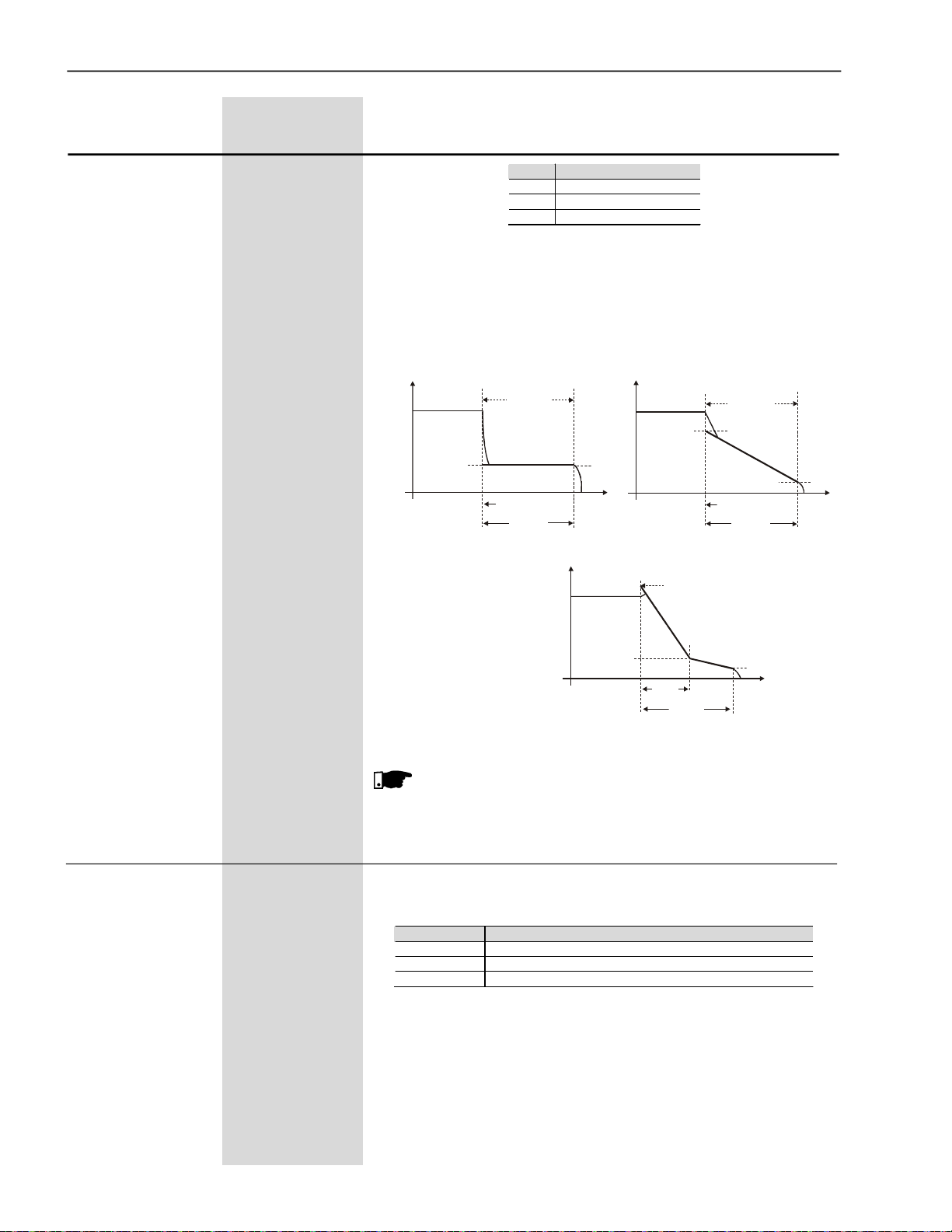
CHAPTER6 - DETAILED PARAMETER DESCRIPTION
Range
[FactorySetting]
Parameter Unit Description/Notes
(1)
P125
1 to 3
StoppingTorque [ 1=Constant]
Characteristics -
Here you can choose the torque limit profile that the Soft-Starter
SSW-06 shall supply to the motor during the stop.
Three different types of torque profiles are available that permit
improvingthespeedperformanceduringthe stop process.
P125 Stop Torque Profile
1 Constant (1 set point)
2 Linear (2 set points)
3 Quadratic (3 set points)
Table 6.12 - Stop torque characteristics
Tn(%)
TnNominal
0
Stop
P125=1
P126
P128
P104
Tn(%)
0
Tn(%)
P126
t(s)
TnNominal
P127
0
TnNominal
Stop
P127
P128
P104
100%Tn
P125=3
P128
P104
Figure 6.8 - Available torque profiles for the stop process
NOTE!
Choose the type of torque control, easier to program and set,
accordingtotheknowledgeaboutthe characteristicsoftheload.
P125=2
P126
t(s)
P126
t(s)
P126 10 to 100
EndStop Torque [ 20 ]
1% Tn of the Motor
98
Here youcan program the end torque limit or constant for the stop,
according to the torque type selected at P125.
P125 Action
1 (Constant) P126 limits the maximum torque during the stop process
2 (Linear) P126 limits the end torque during the stop process
3 (Quadratic) P126 limits the end torque during the stop process
Table 6.13 - Function of P126 according to P125
Formoredetailsaboutprogramming and application,refertoTorque
Controlat P202.
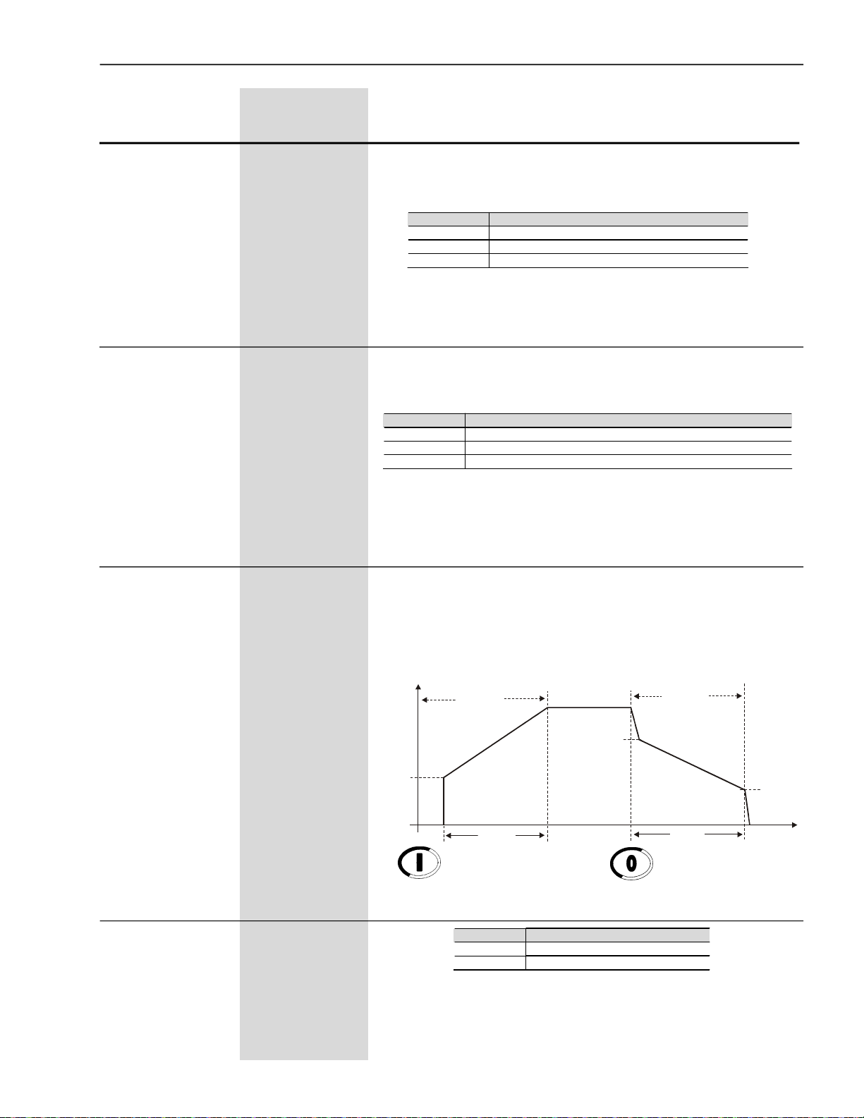
CHAPTER6 - DETAILED PARAMETER DESCRIPTION
Range
[FactorySetting]
Parameter Unit Description / Notes
P127 10 to 100
MinimumStop [ 50 ]
Torque 1%Tn of the Motor
Hereyou canprogramtheinitial torquelimitoranintermediatetorque
limitforthe stop, whenalineartorqueor a quadratic torque has been
selected at P125.
P125 Action
1 (Constant) P127 not used
2 (Linear) P127 limits the torque when the motor is stopped
3 (Quadratic) P127 limits the intermediate torque for the stop
Table 6.14 - Function of P127 according to P125
Formore detailsaboutprogramming and application,refertoTorque
Controlat P202.
P128 1 to 99
Timefor the Minimum [ 50 ]
StopTorque 1% of P104
(1)
P130
0
PumpControl [ 0=Pump I ]
-
Here you can program the time for the intermediate stop torque, as
percent of the maximum time programmed at P104, when the
quadratic torque has been selectedat P125.
P125 Action
1 (Constant) P128 not used
2 (Linear) P128 not used (time equal to 0)
3 (Quadratic) P128time for the intermediate torque limit for the stop process
Table 6.15 - Function of P128 according to P125
Formoredetailsaboutprogrammingandapplication,refertoTorque
Controlat P202.
Thisparameter is reserved forfuturesoftware versionswithhydraulic
pump control type. The current version has been developed for the
control of centrifugal hydraulic pump, considering quadratic motor
loads.
For more details about the Pump Control, see P202.
U(V)
Start 100%Un
P103
Stop
(1)
P140
0 to 1
External By-pass [0=Inactive ]
Contactor -
P101
0
P102
Enable
0 (Inactive) Without external By-pass contactor
1 (Active) With external By-pass contactor
PumpControl
Figure 6.9 - Start and Stop by Pump Control
P140 Action
Table 6.16 - External By-pass contactor
P104
Disable
P105
t(s)
This function is enabled when the installation of an external By-pass
contactorisrequiredthatmustbeconnectedinparalleltotheSoft-Starter
SSW-06.
99
CHAPTER6 - DETAILED PARAMETER DESCRIPTION
Range
[FactorySetting]
Parameter Unit Description / Notes
The modelsfrom 85Ato 820Ahave an internal By-pass contactor.
The models from 950A to 1400A do not have an internal By-pass
contactor.
When P140=1 in the models with an internal By-pass, the internal
By-pass will not enable.
The external By-pass contactor is used:
(1)Models without internal By-pass - To allow the connection of an
external By-pass contactor;
(2)Models with internal By-pass - For instance when a direct start is
required in case of an emergency.Theinternal By-passcontactors
donot permit a directstart.These contactors can beenabledonly
after the motor start has been realized by the thyristors;
(3)ModelswithinternalBy-pass- If themotor stallsfrequentlyduring
By-pass condition.
NOTE!
See the recommended setup at items 3.3 and 3.3.12 for more
information.
(1)(2)
P150
0 to 1
InsideDelta [0=Inactive]
MotorConnection -
P150
0 (Inactive)
1 (Active)
Soft-Starter SSW-06 with standard motor connection
Soft-Starter SSW-06 with inside delta motor connection
Table 6.17 - Motor connection type
Action
SSW-06 offers two operationmodes:Standard Connection or Inside
DeltaMotorConnection.
When a Standard Connection is used, the motor is connected in
series to the Soft-StarterSSW-06 through three cables.
When an Inside Delta Connection is used, the Soft-StarterSSW-06
isconnectedseparatelyin each windingthroughsixcables(seeitem
3.2.5.2).In this typeof connection, thecurrent that flows through the
Soft-Starter SSW-06 is only the current of the inside delta motor
connection, in other words, 58% of the nominal motor current. This
characteristic changestherelation betweentheSoft-StarterSSW-06
nominalcurrentsandthose of themotor.Inthis connection,the SoftStarter can be used with its nominal current dimensioned in the
followingway:
- 1.5 times the nominal motor current during start;
-1.73 times the nominal motor currentduring fullvoltage.
During the start, the relation is lower due to the characteristics that
arecommon tothistypeof connection(insidedelta)the Thyristorsof
the Soft-Starter need to conduct the same current for a lower time
period, increasing with this the losses in the Thyristor during the
start.
Thestandard connectionrequireslessoutputwiring. The InsideDelta
MotorConnectionrequiresdoublewiring, but for shortdistances,this
will be a cheaper option for the Soft-Starter+ motor + wiring set.
100
ATTENTION!
Donot operatethe motorwhen P150 has not been programmed
correctly. Soft-Starter SSW-06 can be seriously damaged when
thisparameter hasnot been programmed correctly.

CHAPTER6 - DETAILED PARAMETER DESCRIPTION
6.3 CONFIGURATIONPARAMETERS - P200to P299
Range
[FactorySetting]
Parameter Unit Description / Notes
P200 0 to 1
Password [ 1 ]
-
(2)
P201
0 to 3
Language Selection [Tobedefined
by the user]
-
P200
0 (Inactive)
1 (Active)
This Parameter allows parameter content changing,
independent of P000
Change of Parameter content is only possible, when P000 is
equal to the password value
With the Factory Setting, the password will be P000=5.
To change the Password, see P000.
Action
Table 6.18 - Password
P201
0
1
2
3
Description
Português
English
Español
Deutsch
(1)
P202
0 to 4
Typeof Control [ 0=Voltage
Ramp ]
-
Table 6.19 - Language selection
P202
0
1
2
3
4
Table 6.20 - Types of control
Type of Control
Voltage Ramp
CurrentLimit
PumpControl
Torque Control
CurrentRamp
Soft-Starter SSW-06 has five starting control types to better match
allapplicationrequirements.
Start by Voltage Ramp
(1)
:
The start by Voltage Ramp is the most used starting method. The
Soft-Starter SSW-06 applies the voltage to the motor without voltage
or current feedback. This method is used for loads with lower initial
torque or quadratic torque.
This type of control can be used as initial operating test.
Start by Current Limit
(2)
:
The maximum current level is maintained during the start and is set
accordingto the applicationrequirements.
Thismethodisusedforloadswithhigherinitial torqueor constanttorque.
This type of control is used for matching the start process to the limits
of the power supply capacity.
Start by Current Ramp
(3)
:
Themaximum current level is limited during the startprocess, however
higherorlowercurrentlimitscanbe set during the beginningof the start
sequence.
101
 Loading...