


SERIAL
COMMUNICATION
MANUAL
SSW-03 and 04
SERIAL INTERFACE
Series SSW-03 and 04
CODE 0899.4457 E/2


0899.4657 E/2
email: astec@weg.com.br
MANUAL OF THE
SERIAL
COMMUNICATION
SSW-03 and 04
Series: SSW-03 and 04
Software: Version 4.XX
ATTENTION!
It is very important to
check if the Soft-Starter
Software version is the
same as indicated above.
WEG AUTOMAÇÃO
Av. Pref. Valdemar Grubba, 3000
89256-900 Jaraguá do Sul, SC – Brasil
Tel.(047)372-4000 – Fax(047)372-4020


_______ CONTENTS______
1 1 2
3
7 7 7 8 8
8 8 9 9
10 10 10 13 13 13 14 15 16 16 17
18
SAFETY NOTICES
1
1.1 Safety Notices in the Manual.......................................
1.2 Safety Notice on the Product.......................................
1.3 Preliminary Recommendations....................................
INTRODUCTION
2
COMMUNICATION
INTERFACES
3
DEFINITIONS
4
TELEGRAM EXAMPLES
5
2.1 About this Manual........................................................
2.2 About WEG Protocol....................................................
3.1 Interface RS-485 .........................................................
3.2 Interface RS-232 .........................................................
3.2.1 Electrical characteristics of the RS-232...............
3.2.2 Cares with the RS-232........................................
3.2.3 RS-232 connections............................................
3.2.4 Description of the Serial communication of the
Soft-Starter
3.2.5 Definition of the Cable for the RS-232 ................
3.2.6 Description of the Master Connector (RJ)...........
3.2.7 Definition of the Cable for the RS-232 PC..........
3.2.8 Description of the PC Connector (DB9)...............
4.1 Used Terms.................................................................
4.2 Block Diagram .............................................................
4.3 Magnitude Standardization..........................................
4.4 Character Format.........................................................
4.5 Protocol........................................................................
4.5.1 Reading Telegram...............................................
4.5.2 Writing Telegram.................................................
4.6 Execution and Telegram Test......................................
4.7 Telegram Sequence.....................................................
4.8 Variable Code..............................................................
4.9 Times...........................................................................
5.1 Example 1....................................................................
5.2 Example 2....................................................................
3
5
18

19 19 20
21 21
VARIABLES OF THE
SERIAL
COMMUNICATION
6
ERRORS AND
PARAMETERS
RELATED TO THE
SERIAL
COMMUNICATION
7
FAULTS AND
CORRECTIVE ACTIONS
8
6.1.1 V00 Indication of the Equipment Type......................
6.1.2 V01 Status Indication of the Soft-Starter...................
6.1.3 V02 Indication of the Soft-starter Errors....................
6.1.4 V03 Selection of the Logic Command.......................
7.1 Parameters Related to the Serial Communication.......
7.2 Errors Related to the Serial Communication................
Faults and Corrective Actions............................................ 22
19
1
SAFETY NOTICES 1
This Manual contains all necessary information for the correct use of the Serial
Communication of the Soft-Starters SSW-03 and SSW-04
This Manual has been written for qualified personnel with suitable training or technical
qualification to operate serial interfaces and theirs respective communications protocols.
1.1 SAFETY NOTICES IN
THE MANUAL
1.2 SAFETY NOTICES ON
THE PRODUCT
The following Safety Notices will be used in this Manual:
DANGER!
If the recommended Safety Instructions are not strictly
observed, this can lead to serious or fatal injuries of
equipment damage.
ATTENTION!
Failure to observe the recommended Safety Procedures
can lead to material damage.
NOTE!
The purpose of this Manual is to supply important
information about the understanding of operation and
good performance of the equipment.
The Following symbols may be attached on the product,
giving information about the safety:
High voltage
Components are sensitive to electrostatic discharge.
Do not touch them
Mandatory connection to ground protection (PE)
Shielded connection to the ground

1 SAFETY NOTICES
2
1.3 PRELIMINARY
RECOMMENDATIONS DANGER!
Only qualified personnel should plan or implement the
installation, start-up, operation and maintenance of serial
interfaces.
Personnel must review the entire Manual of this SoftStarter before, following carefully all safety notices there
indicated.
These personnel must follow all safety instructions
included in the Soft-Starter Manual and/or defines by local
regulations.
If there is any possibility of personnel injury and equipment
damage, that are related to motors driven by motor
starters, please install electromechanical safety devices.
In case of use of remote control (via serial
communication), consider eventual injuries and damages
that can be caused to persons and machines.
Failure to comply with these instruction may result in
personnel injury and/or equipment damage.
DANGER!
Never open energized equipment.
Always connect the frame of the equipment to the ground
(PE) at the suitable connection point.
ATTENTION
The electronic boards have components that are sensitive
to electrostatic discharges. You should never touch any of
the electrical components or connectors. If you find it
necessary to do so, touch before the metallic frame or use
a suitable grounded metallic bracelet.
NOTE!
Communications networks are generally sensitive to
interferences generated by other equipment. In order to
reduce this interference, adopt all recommended
measures.
3
ult identification related to the serial interface of WEG
INTRODUCTION 2
2.1 ABOUT THIS
MANUAL
This Manual describes the installation, start-up, operation
and fa
Soft-Starters.
For more details, training and servicing, please contact:
Servicing:
WEG AUTOMAÇÃO
Tel. (0800) 475767
Fax: (047) 372-4020
NOTE!
For request of information or servicing, please provide
always de following information:
þ Type of WEG equipment;
þ Serial number and manufacturing date indicated on WEG
equipment nameplate;
Software version that is installed in WEG equipment.
2.2 ABOUT WEG
PROTOCOL
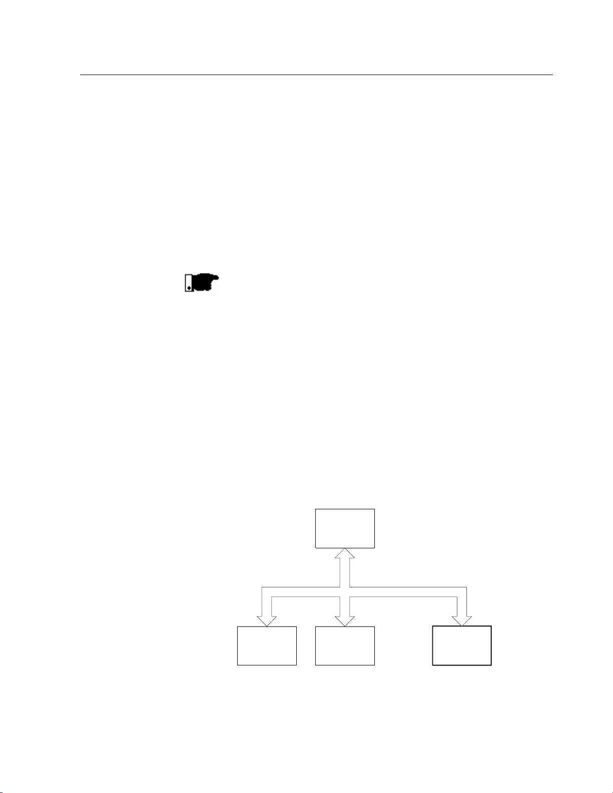
The main purpose of the serial network communication is
the physical connection of several equipment to one or more
masters that so will control though one or two wire pairs all
equipment that are connected do this network:
Master
MESTRE
PC, CLP, etc.
Slave 1
ESCRAVO 1
(converter)
(conversor)
Slave 2
ESCRAVO 2
(converter)
(conversor)
. . .
Slave n
ESCRAVO n
(converter)
(conversor)
n <= 30
WEG Soft-Starters have a Software to control data
transmission and reception though the serial interface, thus
enabling the reception of data sent by the master and the
transmission of data requested by it.

2 INTRODUCTION
4
The baud rate is 9.600Bps and it used an exchange protocol
of enquiry/answer type that meet standard ISO 1745 for
code data transmission.
The mater can perform the following operations related to
each WEG equipment that is connected to the network:
þ Identifications:
• Network number;
• Soft-Starter type;
• Software version.
þ Controls:
• General enabling/disabling;
• Error Reset.
þ Status Recognition:
• Enabling / Disabling;
• Acceleration;
• Current limitation;
• Full voltage;
• Energy saving;
• Deceleration;
• Error.
þ Parameter reading or changing.
Typical examples of WEG network use
• Monitoring at the same time several variables of WEG
Soft-Starters;
• PLC controlling the operation of several WEG SoftStarters in an industrial process.
NOTE!
WEG protocol is the same for all W EG equipment, but the
words for the logic command, basic variables, as well as
parameters can differ from one equipment to other.

5
COMMUNICATION INTERFACES 3
3.1 RS-485 INTERFACE
The physical connection between WEG Soft-Starter WEG is
performed according to one of the standards below:
þ RS-232 (point-to-point, up to 10m);
þ RS-485 (multipoint, with the use of the MIW-02 serial
interface module, with galvanic isolation, up to 1000m.
For the serial communication of the Soft-Starter at WEG
network.
þ This interface allows the connections up to 30 WEG Soft-
Starters to a Master, attributing to each WEG equipment
and address (1 to 30) that must be set at each one.
þ In addition to these 30 addresses, there as two other
addresses to perform special tasks:
• Address 0: any WEG Soft-Starter connected to the
network is required, independently of its address. Only
one Soft-Starter can be connected to network (point-topoint) in order to prevent shot-circuits in the line interface.
• Address 31: a control can be transmitted to all WEG Softstarters in the network simultaneously, without
acceptance recognition.

3 COMMUNICATION INTERFACES
6
standard
þ List of addresses and corresponding ASCII characters:
þ The connection between the network participants is
Address ASCII Address ASCII
0 @ 16 P
1 A 17 Q
2 B 18 R
3 C 19 S
4 D 20 T
5 E 21 U
6 F 22 V
7 G 23 W
8 H 24 X
9 I 25 Y
10 J 26 Z
11 K 27 [
12 L 28 \
13 M 29 ]
14 N 30 ^
15 O 31 _
performed through a pair of wires.
þ The signal levels are accordin g to EIA STANDARD RS-
485 with differential receivers and transmitters.
NOTE!
WEG Soft-Starters SSW-03 and SSW-04 have only serial
interface RS-232. Thus you must use the module of the
serial interface MIW-02 when a serial interface RS-485 is
required.
Module WEG Item No.
MIW-02 417100543
NOTE!
When the Master is fitted with only serial interface RS-232, you must use serial interface module MIW-02, RS232/RS-485, if it has the RTS signal, Request To Send. If the
RTS signal is not available on the Master, you must use a
module that can generate the RTS signal.
For more details, please contact WEG.

7
COMMUNICATION INTERFACES 3
3.2 RS-232 INTERFACE
For communication with WEG Soft-Starters (point-to-point).
þ In this case we have the connection of a Master to a
WEG Soft-Starter.
þ The logical levels meet EIA STANDARD RS-232C that
requires the use of balanced signals.
þ For RS-232 is used one communication cable.
3.2.1 Electrical
Characteristics of
RS-232
þ RS-232:
• Standard: EIA Standard RS-232C.
• Transmission speed: 9.600Bps.
• Max. cable length: 10 metros.
þ Receiver:
Max. input voltage: ± 30V;
Input resistance: > 3KΩ
Level 1 (MARK): < -3V;
Level 0 (SPACE): > +3V.
þ Transmitter:
Current limitation: ~ 10mA;
Output voltage – level 1: < -7V (RL = 3K);
Output voltage – level 0: > +7V (RL = 3K).
3.2.2 Cares with the
RS-232
þ Note please that this interface is not isolated against the
internal electronics from the equipment to which is
connected.
þ Take care with the wiring location, by separating them at
least a distance of 10 cm from the power and control
wiring.
þ It is also a good practice to install the Master as near as
possible to the Serial interface RS-232 of WEG SoftStarter.

3 COMMUNICATION INTERFACES
8
TERMINAL
SYMBOL
DESCRIPTION
1 +5V
+5V
±5%
4 Rx Data reception
5 GND
0V
6 Tx Data Transmission
Length
WEG Item
-
No.
Serial cable RS
-
232 with 0.17m
0307.4790
Serial cable RS
-
232 with 1m
0307.4820
Serial cable RS
-
232 with 3m
0307.4846
T
ERMINAL
SYMBOL
DESCRIPTION
1 Rx Data reception
4 GND
0V
5 nc Free
6 nc Free
3.2.3 RS-232
Connection
3.2.4 Description of the
Serial
communicat ion of
the Soft-Starter
3.2.5 Definition of the
cable for the
RS-232
þ This interface must be connected point-to-point directly.
þ There are two standard WEG cables as described below.
þ Connector of the SSW-03 (XC2) and SSW-04 (X3) for
the RS-232.
2 RTS Request To Send
3 GND 0V
þ The cable that must be used is the standard cable for
WEG serial communication, equipment x serial HMI of
WEG inverters (Human Machine Interface).
3.2.6 Description of the
Master Connector
(RJ)
Serial cable RS-232 with 0.23m 0307.4803
Serial cable RS-232 with 0.32m 0307.4811
Serial cable RS-232 with 2m 0307.4838
þ Master connector with RJ.
2 GND 0V
3 Tx Data transmission

9
Length
WEG Item
-
No.
Serial Cable RS
-
232 PC with 3m
0307.5460
TERMINAL
SYMBOL
DESCRIPTION
1
Free
4
Free
5 0V
6
Free
7 Free
8
Free
9
Free
3.2.7 Definition of the
Cable for RS-232
PC
COMMUNICATION INTERFACES 3
þ The cable that must be used is the standard cable for
WEG serial communication, equipment x PC.
þ It must be connected directly to the PC serial interface.
3.2.8 Description of the
PC connector
(DB9)
þ Serial connector of the PC (DB9).
2 Data reception
3 Data transmission
NOTE!
Avoid to connect equipment to different grounds, since there
can be voltage differences between them and when
connected by their interfaces, this voltage difference can
damage the equipment.
ATTENTION!
Do not use the neutral conductor for grounding purpose.
Use always serial interfaces in RS-485 for long distances.

4 DEFINITIONS
10
4.1 USED
TERMS
4.2 BLOCK DIAGRAM
4.3 MAGNITUDE
STANDARDIZATION
The protocol used for the serial communication between
WEG equipment.
þ Parameters: are those existing in WEG equipment whose
visualization or alteration is possible through the HMI
interface;
þ Variables: are values that have specific functions in W EG
equipment and that can be read, and in some cases,
modified by the master;
þ Basic Variables: are those that can be accessed only
through the serial interface.
SOFT STARTER
VARIÁVEIS
BÁSICAS
PARÂMETROS
The variable change is subject to the following
standardization.
LIGAÇÃO SERIAL MESTRE
VARIÁVEIS
Table of values and function of the parameter content of the Software version V4.XX for
implementation of: changes, monitoring and control through the serial communication.
Parameter
Parameter Function
P00
P01 Initial starting voltage 25 ... 90 (% Un)
P02 Ramp time for voltage increment 1 ... 240 (s)
P03 Voltage step during deceleration 100 ... 40 (% Un)
P04 Ramp time during voltage decrement 1 , 2 ... 240 (s) 1 = oFF
P11 Current limitation during starting 149 , 150 ... 500 (% Un)
P12 Protection against immediate overcurrent 32 ... 200 (% In)
P13
P14 Protection against immediate undercurrent 20 ... 190 (% In)
P15
P21 Motor current setting at % of the In of the switch 49 , 50 ... 200 (% In) 49 = oFF
P22 Rated current of the SSW-04 switch 0 ... 4
It allows to change the parameters via parallel
HMI
Actuation time of the protection against immediate
overcurrent
Actuation time of the protection against immediate
undercurrent
Internal value
range
0 , 1
0 , 1 ... 20 (s) 0 = oFF
0 , 1 ... 200 (s) 0 = oFF
HMI
Indication
0 = oFF
1= on
149 = oFF
0 = 16 A
1 = 30 A
2 = 45 A
3 = 60 A
4 = 85 A

11
DEFINITIONS 4
Rated current of the SSW-03 switch 0 ... 8
P23 Rated voltage of the power supply network 0 ... 9
P24 Analog input gain of the switch current 1 ... 999 X /100 = X,XX
P25 Thermal class of the motor protection 0 ... 5
P26 Motor service factor 80 ... 150 X /100 = X,XX
P27 Self-reset of the thermal memory 0 , 1 ... 600 0 = oFF
P28
P31 Phase sequence 0 , 1
P33 Jog voltage level 25 ... 50 (% Un)
P34 DC braking time 0 , 1 ...10 (s) 0 = oFF
P35 Voltage level of the DC braking 30 ... 50 (% Un)
P41 Pulse time of the starting voltage 1 , 2 ... 20
P42 Pulse level of the starting voltage 70 ... 90 (% Un)
P43 By-pass relay enabling 0 , 1
P44 Energy saver enabling 0 , 1
P45 Pump Control 0 , 1
P46 Parameters for Factory Setting 0 , 1
P47 Auto reset 9 , 10 ... 600 9 = oFF
P50 Fault relay output RL3 1 , 2
Operation mode
(available only in the SSW-03)
0 , 1
0 = 120 A
1 = 170 A
2 = 205 A
3 = 255 A
4 = 290 A
5 = 340 A
6 = 410 A
7 = 475 A
8 = 580 A
9 = 670 A
10 = 800 A
11= 950 A
12= 1100 A
13= 1400 A
0 = 220 V
1 = 230 V
2 = 240 V
3 = 380 V
4 = 400 V
5 = 415 V
6 = 440 V
7 = 460 V
8 = 480 V
9 = 575 V
0 = 5
1 = 10
2 = 15
3 =20
4 = 25
5 = 30
0 = oFF
1 = on
0 = oFF
1 = on
1 = oFF
2 /10 = 0,2 s
0 = oFF
1 = on
0 = oFF
1 = on
0 = oFF
1 = on
0 = oFF
1 = on
1 = disables with
error
2 = enables with
error

4 DEFINITIONS
12
1 = in operation
P51 Programmable relay output RL1 1 ... 3
P52 Programmable relay output RL2 1 ... 3
P53 Programmable digital input 2 0 , 1 ... 3
P54 Programmable digital input 3 0 , 1 ... 4
P55 Programmable digital input 4 0 , 1 ... 4
P56
P57
P61 Start / Stop enabling via HMI or serial com. 0 , 1
P62 Switch address in the communication network 1 ... 30
P63 Verification time of the serial communication 0 , 1 ... 5 (s)
P64 Verification action of the serial communication 1 ... 3
P71 Indication of the Software version XXX XXX /100 = X.XX
P72 Motor current indication (%) of the In of the switch 0 ... 9999 (% In)
P73 Motor current indication (A) 0 ... 9999 (A)
P74 Indication the active power supplied to the load (kW) 0 ... 65535 X /10 = X, X kW
P75 Indication of the Apparent power supplied to the load (kVA) 0 ... 65535 X /10 = X, X kVA
P76
P77 Indication of the voltage applied by the switch (% Un) 0 ... 100 (% Un)
P81
P82 Status indication of the thermal protection of the motor 0 ... 250 250 = error
P96 Back-up of the last activated Hardware error 1 ... 8
P97 Back-up of the penultimate activated Hardware error 1 ... 8
P98 Back-up of the last but two activated Hardware 1 ... 8
P99 Back-up of the first of the four last activated errors 1 ... 8
Programmable analog output
(available only in SSW-03)
Analog output gain
((available only in SSW-03)
Indication of the cos ϕ of the load
Temperature of the heat sinker
(available only in the SSW-04)
0 , 1 ... 4
1 ... 999 X /100 = X,XX
0 .. 99 X /10 = X,X
0 ... 130 (°C)
2 = full voltage
3 = direct.of rot.
1 = in operation
2 = full voltage
3 = DC braking
0 = oFF
1 = error reset
2 = external error
3 =gen. enabling
4 = three wire
communication
0 = oFF
1 = error reset
2 = external error
3 =gen. enabling
4 = direct.of rot.
0 = oFF
1 = error reset
2 = external error
3 =gen. enabling
4 = Jog function
0 = oFF
1 = current (%)
2 = voltage (%)
3 = cos u
4 = therm. status
0 = oFF
1 = on
1 = only E29
2 = ramp disabl.
3 = gen disabling

13
arity
(even parity). Two types of messages are used (by the
4.4 CHARACTER
FORMAT
4.5 PROTOCOL
DEFINITIONS 4
þ 1 start bit;
þ 8 information bits [codify the text character and the
transmission character, taken from the 7 bit code,
according to ISO 646 and supplemented to even p
(eighth bit)];
þ 1 stop bit;
After the start bit follows the less significant bit:
start
bit
The transfer protocol meets ISO 1745 requirements for the
code data transfer.
Are used only text character sequences without header.
The error monitoring is realized by means of the
transmission related the parity of the individual 7 bit
characters, according to ISO 646.
The parity monitoring is realized according to DIN 66219
B2 B3 B4 B5 B6 B7 B8B1START
8 bits of information
STOP
stop
bit
4.5.1 Reading Telegram
Master):
þ READING TELEGRAM: to enquiry the variable content of
the starting switch
þ WRITING TELEGRAM: to change the variable content or
to sent commands to the starting switch.
Note.: Transmission between two inverters is not possible.
The master has the access control to the bus bar.
This telegram allows that the master receives from the SoftStarter the content corresponding to the enquiry code.
In the answer telegram, the Soft-Starter transmits the data
requested by the master and the it completes the
transmission with EOT.

4 DEFINITIONS
14
1) Mestre:
EOT ADR ENQ
CÓDIGO
2) Soft Starter:
ADR STX = ETX BCC
CÓDIGO VAL
TEXTO
þ Reading telegram format:
• EOT: control character End Of Transmission;
• ADR: inverter address (ASCII@, A, B, C, ...) (ADRess);
• CÓDIGO: address of the 5 digit variable codified in
ASCII;
• ENQ: ENQuiry control character;
þ Format of the answer telegram of the Soft-Starter:
• ADR: 1 character – Soft-Starter address;
• STX: control character - Start of TeXt;
• TEXTO: consists in:
• CÓDIGO: variable address;
• " = ": separation character;
• VAL: 4 digit value HEXADECIMAL;
• ETX: control character - End of TeXt;
• BCC: Byte of CheCksum - EXCLUSIVE OR of all bytes
between STX (excluded) and ETX (included.
Note: In some cases the switch answer can be given with:
ADR
NAK
4.5.2 Writing Telegram
This telegram sends data to the variables of the starting
switch.
The switch will answer by indicating if the data were receipt
or not.

15
DEFINITIONS 4
1) Mestre:
1) Mestre:
EOT ADR STX = ETX BCC
2) Soft Starter:
ADR ACK ADR NAK
CÓDIGO VAL
OU
þ Writing telegram format:
• EOT: control character End Of Transmission;
• ADR: address of the Soft-Starter;
• STX: control character Start of TeXt;
TEXTO: consists in:
• CÓDIGO: address of the variable;
• " = ": separation character;
• VAL: value if formed by 4 digits HEXADECIMAL;
• ETX: control character End of TeXt;
• BCC: Byte of CheCksum - EXCLUSIVE OR of all bytes
between STX (excluded) and ETX (included).
þ Format of the answer telegram of the Soft-Starter:
TEXTO
4.6 EXECUTION AND
TEST TELEGRAM
Accepting:
• ADR: Soft-Starter address;
• ACK: control character ACKnowledge;
Non accepting:
• ADR: Soft-Starter address;
• NAK: control character Not AcKnowledge.
This means that the data were not accepted and that the
addressed variable retains its old value.
The Soft-Starters and the master test the telegram syntax.
Below are defined the answers for the respective verified
condition:
þ Reading Telegram:
• Without answer: with wrong telegram structure, control
characters were wrongly received, or the Soft-Starter was
wrong;

4 DEFINITIONS
16
Starters at determined
use longer than the time
address and the basic variables formed by 5 digits (ASCII
4.7 TELEGRAM
SEQUENCE
4.8 VARIABLE CODE
• NAK: CODE corresponding to an inexisting variable or
read-only variable;
• TEXTO: with valid telegrams.
þ Writing Telegram:
• Without answer: with wrong telegram structure, received
control characters are wrong or Soft-Starter address is
wrong;
• NAK: with code corresponding to an inexisting variable,
wrong BCC (Byte of CheckSum), read-only variable, VAL
outside the permitted range for the variable at issue,
operation parameter outside the changing mode.
• ACK: with valid telegrams;
The telegram is processed in the Softtime intervals. Thus, between two telegrams for the same
Soft-Starter it must be assured a pa
sum of the involved telegrams. (see Item 4.9).
The filed designated by CODE contains the parameter
Characters), as follows:

17
Starter, a wait time
4.9 TIMES
Baud rate of data reception / transmission: 9600bps 1bit / 104,2us
Each data word has 10bits 1,04ms
One enquiry telegram has 8 words 8,33ms
One answer telegram to an enquiry has 14 words 14,58ms
One changing telegram has 15 words 15,63ms
One answer telegram to a changing has 2 words 2,08ms
One updating of a requested variable (with immediate answer) 22,91ms
One changing of a written variable (with immediate answer) 17,71ms
NOTE!
DEFINITIONS 4
þ The baud rate of the serial communication of WEG Soft-
Starters WEG is 9600bps.
þ Times of WEG protocol:
The master should maintain between two variable
transmissions to the same Softcompatible with the telegram types to be processed and their
respective answers.

5 TELEGRAM EXAMPLES
18
5.1 EXAMPLE 1 þ Starting time change(P02) to 20s in the Soft-Starter 7 (“;”
= SSW-03).
1) Mestre:
EOT G STX 0 1 ; 0 2 = 0 0 1 4 ETX BCC
end. 7
2) Soft Starter:
2) Soft Starter:
G ACK
5.2 EXAMPLE 2 þ Reading of the inverter output current 10, presuming it
was 100A at the enquiry moment. (“;” = SSW-03).
1) Mestre:
EOT J 0 1 ; 7 3 ENQ
end. 10
2) Soft Starter:
2) Soft Starter:
J STX 0 1 ; 7 3 = 0 0 6 4 ETX BCC
end. 10
NOTE!
The examples above presume that the used Soft-Starter is a
SSW-03. When a SSW -04 is used, the value “;” of the code
should be changed to “<”.

VARIABLES OF THE SERIAL COMMUNICATION 6
19
0 =
0 =
0 =
0 =
0 =
0 =
0 =
0 =
0 =
0 =
0 =
0 =
0 =
6.1 BASIC VARIABLES
6.1.1 V00
6.1.2 V01
6.1.3 V02
(code 00x00)
þ Indication of the equipment type.
þ Reading variable;
(code 00x01)
þ Indication of the Soft-Starter status.
Reading variable, which bits have the following meaning:
LSB
0 0 = disabled 1 = enabled
1
2
3
4
5
6
7
8
9
10
11
12
13
14
15
MSB
general disabling 1 = general enabling
free 1 = in jog
free 1 = In acceleration
free 1 = in current limiting
free 1 = at full voltage
free 1 = in energy saver
free 1 = in deceleration
reserved
free 1 = in DC braking
free 1 = In changing the direction of
clockwise 1 = Counter-clockwise
reserved
free 1 = with hardware error
without power supply 1 = with power supply
without error 1 = with error
(code 00;02)
rotation
þ Indication of the Soft-Starter error.
þ Reading variable which bits have the following meaning:
Serial Error (byte-high)
Hardware Error (byte-low)
Errors:
Serial Error Hardware Error
15 14 13 12 11 10 9 8 7 6 5 4 3 2 1 0
MSB LSB

6 VARIABLES OF THE SERIAL COMMUNICATION
20
0 =
0 =
0 =
0 =
0 =
1 =
1 =
1 =
1 =
Error code: error number in hexadecimal
6.1.4 V03
Ex.: E00 Ü 00H
E01 Ü 01H
E10 Ü 0AH
(code 00;03)
þ Selection of the logic control.
þ Writing variables, which bits have the following meaning::
MSB
0
1
2
3
4
5
6
7
8 1 = Enabling/disabling
9
10
11
12
13
14
15
MSB
Disables 1 = enables
General enabling 1 = General disabling
Without jog 1 = com jog
Clockwise 1 = Counter-clockwise
Reserved
Reserved
Reserved
free 1 = resetting
General enabling/disabling
jog
clockwise
reserved
reserved
reserved
Switch " reset " when error occurs
þ BYTE HIGH (8-15): desired action mask. The
corresponding bit should be set to 1 to enable this
action.
þ BYTE LOW (0-7): logic level of the desired action.
NOTE!
The reset acts only when the Soft-Starter has hardware
error.
NOTE!
To use the Jog control and the reversal of the direction of
rotation via serial communication, you must set the following
parameters: P54=4, P55=4 and P61=on.

21
7.1 PARAMETERS
RELATED TO THE
SERIAL
COMMUNICATION
ERRORS AND SERIAL PARAMETERS 7
þ P61 – Controls via HMI and Serial or via Digital Inputs.
þ P62 – Switch address on the communication network.
þ P63 – Verification time of the Serial Communication.
þ P64 – Verification Action of the Serial Communication.
7.2 ERRORS RELATED
TO THE SERIAL
COMMUNICATION
þ They do not cause WEG Soft-Starter lockout;
þ They do not deactivated the fault relay;
þ The inform only on the display and in the logic status
word.
Types of errors:
• E22: longitudinal parity error (BCC);
• E24: parameter changing attempt can be realized only
with stopped motor;
• E25: inexisting variable;
• E26: desired value outside the permitted limits;
• E27: writing attempt on read -only variable or logic control
is disabled;
• E29: cyclic serial communication error interrupted.
Note:
These errors can be observed through the reading if the
status variable of WEG equipment.
NOTE!
Error E29 may lockout the Soft-Starters.
This protection is used in installations where the Soft-Starter
has to take a decision when a communication fault occurs
between the master and the Soft-Starter.
NOTE!
Please take car with the parameter compatibility. For more
details about parameter incompatibilities, see please Manual
of WEG Soft-Starters.

8 FAULTS AND CORRECTIVE ACTIONS
22
No communication with
Master reads but does not
change the Soft-Starter
Problems:
Soft-Starter:
parameters:
Corrective Actions:
þ Check if telegram format is correct.
• Equipment Code;
• Byte of BCC is correct;
• Parity;
• Word length.
þ Check all ca ble connections of the serial communication
e and check if power supply of all connected equipment
is correct.
þ Check if the baud rate of the master is 9600bps.
þ Check if the Soft-Starter address (P62) is the same to
which the master is sending the telegrams.
þ When a RS-485 is used and the master is using RS-
232/RS-485 inverter, check if there is present a RTS
signal.
þ Check if the format of the changing telegrams is correct.
þ Check if there is no writing attempt on a read-only
variable.
þ Check if this variable can be changed with enabled
motor.
Random indications of serial
errors in the serial
communication:
þ When installed in communication network with RS-485:
• Check all serial communication cables in the network
and their shields;
• Check if all grounding points are grounded correctly;
• Check if only the network terminal points are fitted with
termination resistors;
þ Check the cables of all RS-232-connections. They
should be as short as possible and be laid separately
from the serial communication cables.
 Loading...