

Page 1
Information
- -
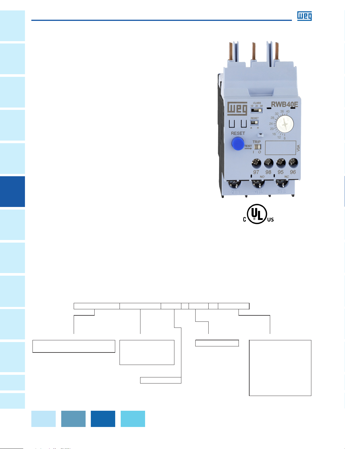
RWM - Solid State OL for CWM 40: 40A Contactor A4U002: 0.4 - 2.0A
RWB - Solid State OL for CWB 112: 112A Contactor A4U008: 1.6 - 8.0A
420: 420A Contactor A4U025: 5 - 25A
840: 840A Contactor A4U040: 8 - 40A
A4U056: 14 - 56A
A4U112: 28 - 112A
E: Electronic OL A4U250: 50 - 250A
A4U420: 85 - 420A
A4U840: 170 - 840A
OL Relay Type
Power Poles
3: 3-Phase Relay
Overload Current Settings
A4U040
E
Solid-State Overload Relay Catalog Number Sequence
Contactor Series
Contactor Frame
RWB
40
3
General
Overloads
Solid-State Overload Relays
Protection
Circuit
Disconnect
Switches
Protectors
Motor
Contactors Power
• 3-pole solid state overload relays with adjustable
Overloads Relays Pushbuttons
• Self-powered
• Wide adjustment range (5:1)
• Thermal memory
• Phase loss protection (less than 5 seconds)
• Phase unbalance protection (>40% between
Enclosed
Starters
• Temperature compensated (-20 °C up to +60 °C)
• Manual or automatic reset modes
•
• Separate mounting is possible with accessories
RW-E
The new RW_E Solid State Overload relays are developed with
cutting edge technology according to the most demanding
standards worldwide� With its wide current/AMP setting; the
RW_E OL Relay can be used for protection of electric motors of
different power ratings� The benefit is versatility and flexibility
for manufacturers due to the possibility of standardization of
control panels� This Solid State Overload Relay can be directly
mounted on WEG Contactors (CWM and CWB lines) providing
very reliable and flexible motor starter units� The RW_E counts
on two independent and highly reliable built in auxiliary contacts
that assure the motor is switched off when a failure occurs�
Standard Features:
trip class: 10, 20 and 30
phases)
UL File No� E189202
Direct mounting on CWB9���38 and CWM9���105
contactors
1NO + 1NC built in auxiliary contacts
and Pilot
Lights
Terminal
Blocks
Correction
Factor
Appendix
A
Appendix
B
Chart intended as reference only and not to create part numbers.
Data is subject to change without notice.
Page 2
Overloads
Solid-State Overload Relays
Suitable for Great Variety of Applications
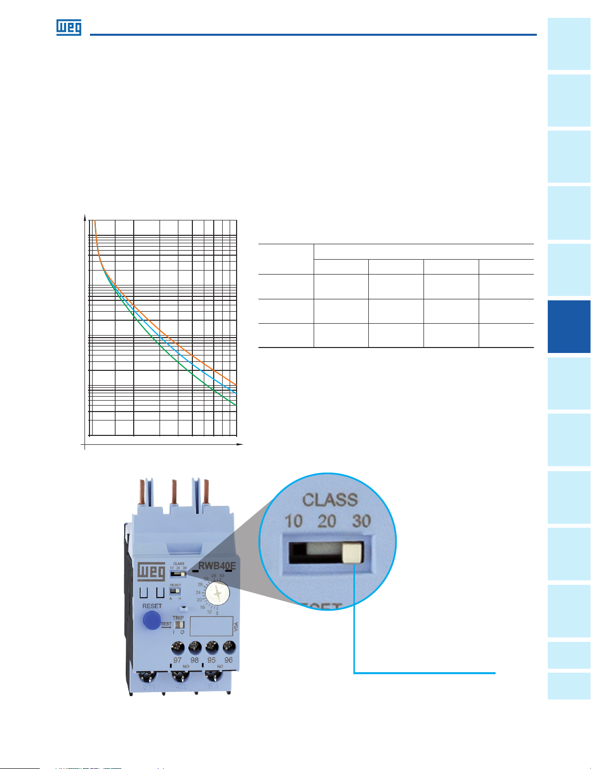
The solid-state overload relays RW_E are suitable to protect motors in a wide range of industrial applications including
those where long starting time is required� This way, motors on low, medium or heavy duty applications can be properly
protected just by selecting the proper trip class (10, 20 or 30 according to IEC 60947-4-1) in the DIP-switches�
Additionally, the microprocessed electronic circuits of RW_E are temperature compensated according to IEC 60947-4-1,
which means that throughout the temperature range of -20 °C up to +60 °C, the tripping point is not affected and it
performs consistently without undesirable tripping�
The RW_E also features thermal memory which assures that the heating and cooling effects of motors are modeled and
proper protection is guaranteed even after downtime periods�
t(s)
10,8 00
10,000
5,000
2,000
1,000
500
200
100
Tripping time
50
20
10
5
2
1
1.0 5 1.5 2 3 4 5 6 7 8 9 10
Ie x Current setti ng
IEC 60947-4-1
Trip class 30
Trip class 20
Trip class 10
(A)
Trip class
1.05 x Ir 1.2 x Ir 1.5 x Ir 7.2 x Ir
10 - Tp <2h Tp <4min 4 <Tp ≤10s
20 - Tp <2h Tp <8min 6 <Tp ≤20s
30 - Tp <2h Tp <12min 9 <Tp ≤30s
Multiples of current setting
General
Information
Circuit
Protection
Switches
Disconnect
Protectors
Starters
Enclosed
Relays Overloads Contactors Motor
Data is subject to change without notice.
Trip class dip-switch
WEG Automation - Products and Solutions | 221
Lights
and Pilot
Pushbuttons
Blocks
Terminal
Power
Factor
Correction
A
Appendix
B
Appendix
Page 3
Information
General
Overloads
Solid-State Overload Relays
Protection
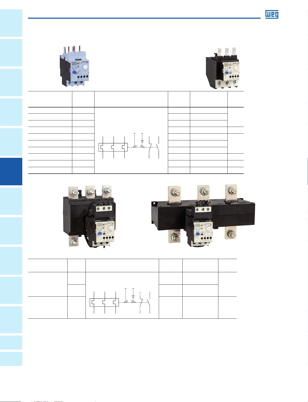
RW_E Solid-State Overload Relays from 0.4 up to 840 A
Circuit
Disconnect
Switches
Protectors
Motor
Contactors Power
Overloads Relays Pushbuttons
Note: Not to be used in si ngle -pha se application s.
For direct mounting
on contactors
CWB9...38 0.4...2
Current
range
A
Diagram
Max fuse
(gL/gG)
Catalog Number
A
16 RWB40E-3-A4U002 0.250
CWB9...38 1.6...8 32 RWB40E-3-A4U008
CWB9...38 5...25 63 RWB40E-3-A4U025
5L3
6T3
Tes t
Reset
95
97
96
98
CWB9...38 8...40 125 RWB40E-3-A4U040 0.250
CWM9...40 0.4...2 16 RWM40E-3-A4U002
CWM9...40 5..25 63 RWM40E-3-A4U025
CWM9...40 8...40 125 RWM40E-3-A4U040 0.918
2T1
1L1
3L2
4T2
CWM50...105 14...56 160 RWM112E-3-A4U056 0.918
CWM50...105 28...112 250 RWM112E-3-A4U112 0.918
Weight
kg
0.250CWM9...40 1.6...8 32 RWM40E-3-A4U008
Starters
and Pilot
Lights
Blocks
Correction
Factor
A
Enclosed
For separate mounting
or by connector links
Terminal
CWM112...500
CWM150...800 170....840 1,250 RWM840E-3-A4U840 4,150
Note: Not to be used in si ngle -pha se application s.
Note: 1) RWM8 40E mo del allows t wo dif fer ent t ypes of conne ctio n to cont actor:
a) By connecti ng the c ontactor ca bles to relay busba rs;
Appendix
b) By removing th e rela y busb ars and usi ng the Ø3 2 mm win dow for t he pas sage o f the contact or cab les.
Current
range
1)
A
Diagram
50...250
Tes t
85...420 710 RWM420E-3-A4U420
2T1
1L1
3L2
4T2
5L3
6T3
Reset
95
97
96
98
Max fuse
(gL/gG)
A
Catalog Number
500 RWM420E-3-A4U250
Weight
kg
2,520
Appendix
B
Data is subject to change without notice.
Page 4
Overloads
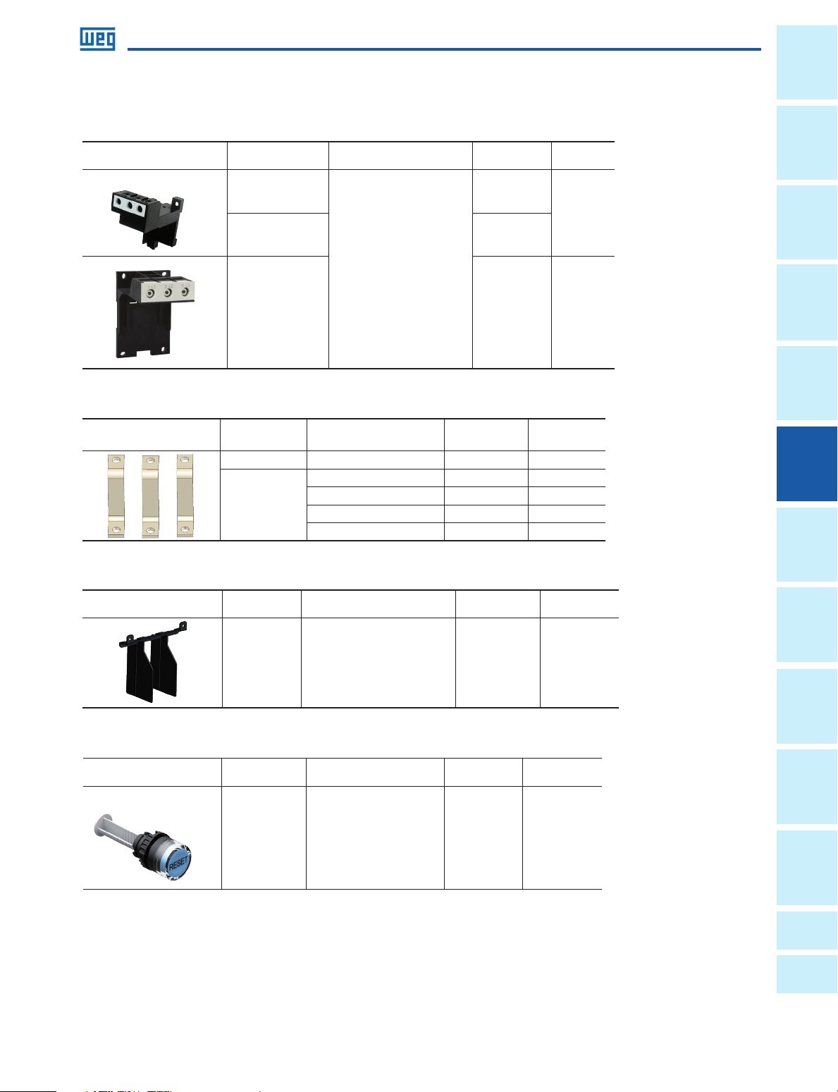
Accessories
Mounting Kit
Image For use with relays Description Catalog Number
RWM40E
RWB40E BF27D-2D
Enables the overload relay to be
mounted directly to a panel via
screws or 35 mm DIN rail
RWM112E BF112 0.230
Connector Links for Direct Mounting of Overload Relay on Contactor
Image
For use with
relays
RWM112E CWM112/150 GA117D 0.135
RWM420E
For use with contactors Catalog Number
CWM150 GA317-1D 0.250
CWM180 GA317-2D 0.270
CWM250/300 GA317-3D 0.630
CWM400 GA317-10D 0.500
BF27D
Solid-State Overload Relays
Weight
kg
0.050
Weight
kg
General
Information
Circuit
Protection
Switches
Disconnect
Protectors
Phase Barriers
Image
For use with
relays
RWM420E
Reset Pushbutton with Shaft
Image
For use with
relays
RW_E
Description Catalog Number
Contains 1 set of plastic insulators
(top / bottom) and fixing screws to
be used where the overload relay
power terminals external
dimension exceed the busbar
external dimension
Description Catalog Number
Blue Flush pushbutton Engraved Reset - with shaft.
Length: max. 250 mm and
min. 22.5 mm
IBRW317 0.044
Weight
kg
CSW-BHF437 0.032
Weight
kg
Starters
Enclosed
Relays Overloads Contactors Motor
Lights
and Pilot
Pushbuttons
Blocks
Terminal
Power
Factor
Correction
A
Appendix
Data is subject to change without notice.
B
Appendix
WEG Automation - Products and Solutions | 223
Page 5

Information
General
Overloads
Solid-State Overload Relays
Protection
Technical Data
Circuit
General Data
Disconnect
Switches
Protectors
Motor
Contactors Power
Overloads Relays Pushbuttons
Enclosed
Starters
Notes: 1) Dire ct mounting o n contactor o r dire ctly o n the panel via scre ws or 35 mm D IN rai l when u sing t he mou nting k it acc esso ry (BF27D and BF112)
Product model RWM40E / RWB40E RWM112E RWM420E RWM840E
Standards IEC 60947-4-1, IEC 60947-5-1, IEC 60947-1, UL 60947-1, UL 60947-4-1A and UL 508
Rated insulation voltage U
(pollution degree 3)
i
Rated impulse withstand voltage U
IEC 60947-4-1 (V) 690 100
UL, CSA (V) 600
(IEC 60947-1) (kV) 6 8
imp
Rated operational frequency (sinusoidal networks) (Hz) 50/60
Three phase loads Yes
Suitable for use
Single phase / two phase loads No
DC current loads No
Trip class (IEC 60947-4-1) 10, 20 or 30 - selectable
Additional featured protections
Reset
Phase loss Yes / less than <5s
Phase unbalance Yes / >40%
Manual / minimum downtime for
reset
Automatic / minimum downtime
for reset
Yes / instantaneous
Yes / ≥90s
Maximum operation per hour (ops./h) 30
Protection degree (IEC 60529)
Main contacts IP10 IP00
Auxiliary contacts IP20
Mounting 1) 2)
Mechanical shock resistance - 1/2 sinusoid 15 g / 11ms
Vibration resistance (IEC 60068-2-6) 6 g / 30...300 Hz
Transport and storage -50 ºC...+80 ºC
Ambient temperature
Operating -20 ºC...+60 ºC
Temperature compensation -20 ºC...+60 ºC
Altitude 2,000 m
2) Dire ct mounting o n conta ctor w hen us ing the Conne ctor L ink GA117 / GA317 accessor y or directly on the pa nel via screws.
and Pilot
Lights
Blocks
Correction
Factor
A
B
Main Contacts
Product model RWM40E / RWB40E RWM112E RWM420E RWM840E
Rated operational voltage Ue
Current setting / max fuse (gL/gG) (A)
Terminal
Setting current / average power dissipation per pole (W)
Notes: 1) Dire ct mounting o n contactor o r dire ctly o n the panel via scre ws or 35 mm D IN rai l when u sing t he mou nting k it acc esso ry (BF27D and BF112);
2) Dire ct mounting o n conta ctor w hen us ing the Conne ctor L ink GA117 / GA317 accessor y or directly on the pa nel via screws.
Appendix
Appendix
IEC 60947-4-1 (V) 690 100
UL, CSA (V) 600
0.4...2 / 16
1.6...8 / 32
5...25 / 63
14...56 / 160
28....112 / 250
50...250 / 500
85...420 / 710 170...840 / 1,250
8...40 / 125
0.4...2 / 0.07
1.6...8 / 0.06
5...25 / 0.38
14...56 / 2
28....112 / 2.6
50...250 / 12
85...420 / 12
8...40 / 1.5
170...840 / 14.5
Data is subject to change without notice.
Page 6

Overloads
Solid-State Overload Relays
Technical Data
Auxiliary Contacts
Product model RWM40...840E / RWB40E
Rated insulation voltage Ui
(pollution degree 3)
IEC 60947-4-1
UL, CSA (V) 600
Rated impulse withstand voltage Uimp (IEC
60947-1)
Rated operational voltage Ue
IEC 60947-4-1
UL, CSA (V) 600
Rated thermal current Ith ≤ 60 ºC) (A) 5
Rated operational current Ie
24 V (A) 3
AC-14/AC-15 (IEC 60947-5-1)
120 V (A) 3
250 V (A) 1.5
24 V (A) 2
60 V (A) 0.4
DC-13 (IEC 60947-5-1)
110 V (A) 0.22
125 V (A) 0.22
250 V (A) 0.1
NEMA control circuit ratings UL, CSA
Short-circuit protection with fuse (A) 6
Minimum voltage / admissible current (IEC 60947-5-4)
(V) 250
(kV) 4
(V) 250
C300 / R300
12 V / 10 mA
General
Information
Circuit
Protection
Switches
Disconnect
Protectors
Terminal Capacity and Tightening Torque - Main Contacts
Product model BF27D RWM40E / RWB40E RW112E BF112
Type of screw
M4 M3.5 M10 M10
Flat / Phillips #2 Flat / Phillips #2 Allen #4 Allen #4
Cable size
Flexible cable (mm²)
1.5...10 - - -
Cable with terminal / rigid cable (mm²) 1.5...6 - - -
AWG wire 16...10 - - -
Tightening torque (Nm) 2.3 - - -
Flexible cable (mm²)
- 1...10 2.5...35 2.5...35
Cable with terminal / rigid cable (mm²) - 1...10 2.5...35 2.5...35
AWG wire - 16...8 14...2 14...2
Tightening torque (Nm) - 1.7 6 6
Product model RWM420E RWM840E
Type of screw
Cable with terminal (mm²) 2 x (25...150) 2 x (60 x 10)
Busbar (A x B x C) (mm) 25 x 18.5 x 12.5 31.7 x 28.3 x 15
A
C
B
M10
Hexagon Head
M12
Hexagon Head
Tightening torque (Nm) 26 26
Terminal Capacity and Tightening Torque - Auxiliary Contacts
Product model RWM40...840E / RWB40E
Type of screw
Cable size
Cable with or without terminal (mm²)
AWG wire 16...12
Tightening torque (Nm) 0.8
Flat / Phillips
#1
1 x 1...2.5
Starters
Enclosed
Relays Overloads Contactors Motor
Lights
and Pilot
Pushbuttons
Blocks
Terminal
Power
Factor
Correction
A
Appendix
B
Appendix
Data is subject to change without notice.
WEG Automation - Products and Solutions | 225
Page 7

Information
L1
L1
L1 L2 L3
General
Overloads
Solid-State Overload Relays
Protection
Technical Data
Circuit
Motor Protection - Alternating Current
Disconnect
Switches
Protectors
Motor
Contactors Power
Overloads Relays Pushbuttons
Typical Connection - Contactor + Overload Relay
3-pole
L2 L3
L1
1 3 5
K1
1
2
1
FT1
FT1
214 6
2
U1 V1
U1 V1 W1
42 6
3 5
M
M
1~
3~
5
3
6
4
5
3
6
4
W1
Starters
and Pilot
Lights
Blocks
Correction
Factor
A
Direct On Line Starter (1 Direction of Rotation) Direct On Line Starter (2 Directions of Rotation)
Enclosed
L1
1
1
0
0
2
2
1
1
F
F
2
2 22
3
13
3
13 13
K1
R
K1
R
4
14
14
4
21
21
K2 K1
K2
22
22
A2
A2
K1
K1
A1
A1
95
95
95
FT1
FT1
9696
96
N
K2
1
1
R
R
2
3
13
3
K2
F
K2
F
4
14
14
4
21
21
K1
22
22
A2
A2
K2
A1
A1
Terminal
Appendix
N
L1
FT1
FT1
3
3
I
I
4
4
95
95
95
9696
96
A2
A2
K1
K1
A1
A1
1
1
0
0
2
2
13
13
K1
K1
14
14
Appendix
B
Data is subject to change without notice.
Page 8

Overloads
94,1
5
5
45
73,2
97,61
85,6
96
84,1
84,4
96
84,1
Dimensions (mm)
RWM40E RWB40E
97,61
97. 61
73,2
73.2
45
RWM40E + BF27
85,6
85.6
94.1
BF27D
BF27D
45
45
Solid-State Overload Relays
84,4
84.4
84.1
General
Information
Circuit
Protection
Switches
Disconnect
96
Protectors
106,5
106.5
4,5
4,5
DIN
35 mm
45
45
DIN 35 mm
RWM40E
RWM40E
6,8
6,8
6.8
4,5
4,5
4.5
35
35
35
60
60
60
Starters
Enclosed
Relays Overloads Contactors Motor
Lights
and Pilot
Pushbuttons
Blocks
Terminal
4.5
Power
Factor
5
Correction
A
Appendix
B
Appendix
Data is subject to change without notice.
WEG Automation - Products and Solutions | 227
Page 9

Information
66
85,7
111,45
112,1
111,45
75
106
121,9
117,2
General
Overloads
Solid-State Overload Relays
Protection
Dimensions (mm)
Circuit
RW M 112E
Disconnect
Switches
Protectors
Motor
Contactors Power
Overloads Relays Pushbuttons
RW M 112E + BF112
Enclosed
Starters
112,1
66
75 121.9
112.1
85,7
85.7
111.4 5
Lights
Correction
and Pilot
Terminal
Blocks
Factor
Appendix
A
Appendix
B
Tri l h o
DIN
TRILHO DIN
116,4
116 . 4
58
58
106
7.4
7,4
7.4
7,4
119,3
119 . 3
117. 2
Data is subject to change without notice.
Page 10

Overloads
184,1
50
120
155
169,6
Dimensions (mm)
RWM420E
120
45 45
155
93
130
93
130
40
40
Solid-State Overload Relays
General
Information
Circuit
Protection
169.6
4545
25
25
50
50
Switches
Disconnect
Protectors
5
5
109,9
109. 9
Starters
Enclosed
RWM840E
18 4 .1
Ø13
31,7
31.7
80 80
80 80
265
265
250
Ø5
Ø5
250
Ø13
120
60
60
150
150
120
50,25
50.25
9.5
90
90
Relays Overloads Contactors Motor
Lights
and Pilot
Pushbuttons
Blocks
Terminal
Power
Factor
Correction
A
Appendix
50
Data is subject to change without notice.
WEG Automation - Products and Solutions | 229
B
Appendix
Page 11

Information
360° 360°
General
Overloads
Solid-State Overload Relays
Protection
Dimensions (mm)
Circuit
RWM420E + IBRW317
Disconnect
Switches
Protectors
Motor
Contactors Power
Overloads Relays Pushbuttons
Enclosed
Starters
97
50
255
RWM40...840E / RWB40E
and Pilot
Lights
Terminal
Blocks
Correction
Factor
Appendix
A
Appendix
B
Mounting Position
Data is subject to change without notice.
Page 12

Overloads
C
A
121,8
130
106
64,5
Dimensions (mm)
CWM9...105 + RWM40...112E and CWB9...38 + RWB40E
DIN rail
TRILHO DIN
35 mm
35mm
B
B
C A
Contactor
CWM9...18
CWM25
CWM32/40
CWM50...80
CWM95/105
CWB9...18
CWB25...38
Solid-State Overload Relays
Type of
contactor coil
CA
CC
CA
CC
CA 98.6
CC 118.6
CA
CC
CA
CC
CA
CC
CA
CC
A B C
94.3
125.1
94.9
124.8
158 45
159.3 45
166.5 55
122.6 202.7 66
126 201.1 75.4
89.5
98.7
93
102.2
163.1
166.5
General
Information
Circuit
Protection
Switches
Disconnect
Protectors
45
CWM112 + RWM112E + BF112
100
100
130
64.5
106
121.8
B
B
A
A
DIN 35 mm
DIN 35mm
146
146
GA117 D
GA117D
BF112
BF112
RWM112E
RWM112E
Starters
Enclosed
Relays Overloads Contactors Motor
Lights
and Pilot
Pushbuttons
Blocks
Terminal
Power
Factor
Correction
CWM112 A B
AC conventional coil - 318.5
Electronic coil 326.5 318.5
Data is subject to change without notice.
A
Appendix
58
58
B
Appendix
WEG Automation - Products and Solutions | 231
Page 13

Information
145
225
62
110
C
A
FE
D
General
Overloads
Solid-State Overload Relays
Protection
Dimensions (mm)
Circuit
CWM112...300 + RWM112/420E
Disconnect
Switches
Protectors
Motor
Contactors Power
Overloads Relays Pushbuttons
Enclosed
Starters
G
G
C
A
FED
Connector Link
B
B
GARRA DE FIXAÇÃO
Contactor Connector links Overload relay A B C D E F G
CWM112/150 GA117D RWM112E 147 325
CWM112/150 GA317-1D RW420E 166 343
121.5
CWM180 GA317-2D RW420E 172 358 139 52.5 160 110
106 64
60.5
110
130 100
CWM250/300 GA317-3D RW420E 181 380 148.4 55 180 120
and Pilot
Lights
Blocks
Correction
Factor
A
B
CWM400 + RWM420E
Ø9
9
5
5
215
215
225
Terminal
62
Appendix
110
Appendix
145
60
50
163
60
50
163 204
429
429
204
CWM400
CWM400
GA317-10 D
GA317-10D
RWM420E
RWM420E
Data is subject to change without notice.
 Loading...