

Page 1
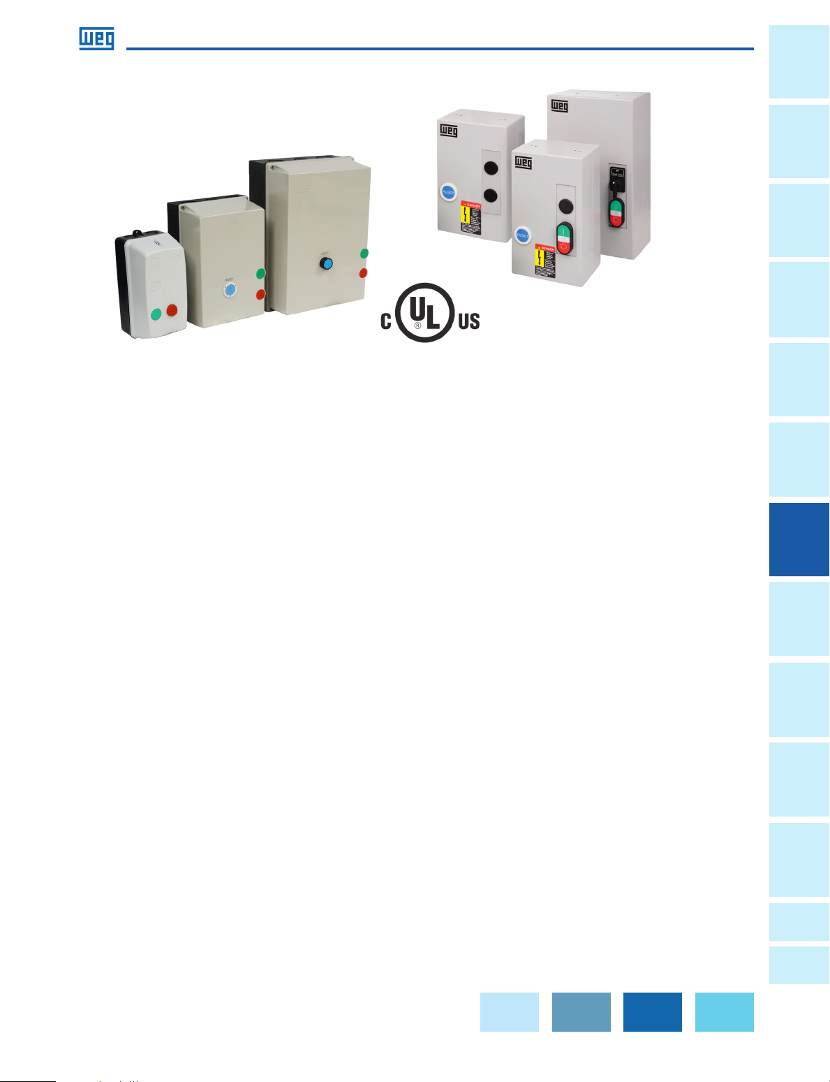
Enclosed Starters
ESW/PESW
UL File No� E202315
WEG offers non-reversing and non-combination magnetic starters up to 75HP
at 460Vac (105A)� Featuring components that meet IEC design standards and
UL horsepower ratings, incorporating WEG contactors and overload relays, the
magnetic starters are ideal to protect and operate motors, ensuring smooth
operation year-after year�
Non-Combination Starters
General
Information
Circuit
Protection
Switches
Disconnect
Protectors
Three series are available:
• Metallic Type 1 – ESW Series
• Non-Metallic Type 4X – PESW Series
• Metallic Type NEMA 7/9 - ESWX Series
WEG ESW and PESW starters are pre-wired from the factory
and recommended for all single and three phase
applications where magnetic starters can be applied�
Standard Features
• High horsepower ratings in four compact sizes
• Fast acceleration and high initial torque
• Bimetallic Overload Relays – class 10
• Adjustable trip current
• Ambient temperature compensated
• Phase-loss sensitivity protection
• Selectable Manual or Automatic RESET
• Electrically isolated NO-NC auxiliary contacts
• Easy to install and setup
Starters
Enclosed
Relays Overloads Contactors Motor
Lights
and Pilot
Pushbuttons
Blocks
Terminal
Power
Factor
Correction
Data is subject to change without notice.
A
Appendix
B
Appendix
Page 2
Enclosed Starters
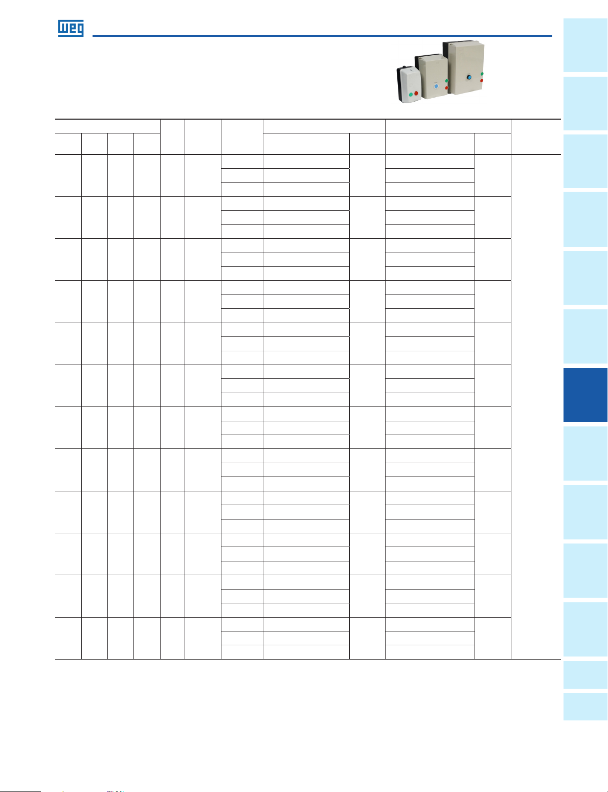
PESW Series - Non-combination Across the line starter
Three-Phase Enclosure Type - 4X
Max. UL Horsepower
200V 230V 460V 575V Catalog Number
- - 1/2 1/2 05 0.8 - 1.2
- - 3/4 1 05 1.2 - 1.8
1/2 1/2 1 2 05 1.8 - 2.8
3/4 3/4 2 3 05 2.8 - 4.0
1 1-1/2 3 5 05 4.0 - 6.3
2 2 5 5 05 5.6 - 8.0
2 3 5 7-1/2 05 7.0 - 10
3 3 7-1/2 10 05
3 5 10 15 05 11 - 17
5 7-1/2 15 15 05 15 - 23
10 10 20 25 06 22 - 32
10 10 25 25 06 25-40
conti nued on n ext page
Box
Setting
Range
8.0 -
12.5
Coil
Voltage
120 PESW-B9D15EX-R57
208-240 PESW-B9V24EX-R57 PESW-B9V24AX-R57
480 PESW-B9D39EX-R57 PESW-B9D39AX-R57
120 PESW-B9D15EX-R58
208-240 PESW-B9V24EX-R58 PESW-B9V24AX-R58
480 PESW-B9D39EX-R58 PESW-B9D39AX-R58
120 PESW-B9D15EX-R59
208-240 PESW-B9V24EX-R59 PESW-B9V24AX-R59
480 PESW-B9D39EX-R59 PESW-B9D39AX-R59
120 PESW-B9D15EX-R60
208-240 PESW-B9V24EX-R60 PESW-B9V24AX-R60
480 PESW-B9D39EX-R60 PESW-B9D39AX-R60
120 PESW-B9D15EX-R61
208-240 PESW-B9V24EX-R61 PESW-B9V24AX-R61
480 PESW-B9D39EX-R61 PESW-B9D39AX-R61
120 PESW-B9D15EX-R62
208-240 PESW-B9V24EX-R62 PESW-B9V24AX-R62
480 PESW-B9D39EX-R62 PESW-B9D39AX-R62
120 PESW-B9D15EX-R63
208-240 PESW-B9V24EX-R63 PESW-B9V24AX-R63
480 PESW-B9D39EX-R63 PESW-B9D39AX-R63
120 PESW-B12D15EX-R64
208-240 PESW-B12V24EX-R64 PESW-B12V24EX-R64
480 PESW-B12D39EX-R64 PESW-B12D39AX-R64
120 PESW-B18D15EX-R66
208-240 PESW-B18V24EX-R66 PESW-B18V24AX-R66
480 PESW-B18D39EX-R66 PESW-B18D39AX-R66
120 PESW-B25D15EX-R67
208-240 PESW-B25V24EX-R67 PESW-B25V24AX-R67
480 PESW-B25D39EX-R67 PESW-B25D39AX-R67
120 PESW-B32D15EX-R68
208-240 PESW-B32V24EX-R68 PESW-B32V24AX-R68
480 PESW-B32D39EX-R68 PESW-B32D39AX-R68
120 PESW-B38D15EX-R69
208-240 PESW-B38V24EX-R69 PESW-B38V24AX-R69
480 PESW-B38D39EXR69 PESW-B38D39AX-R69
RESET only START/STOP + RESET
Catalog Number
PESW-B9D15AX-R57
PESW-B9D15AX-R58
PESW-B9D15AX-R59
PESW-B9D15AX-R60
PESW-B9D15AX-R61
PESW-B9D15AX-R62
PESW-B9D15AX-R63
PESW-B12D15AX-R64
PESW-B18D15AX-R66
PESW-B25D15AX-R67
PESW-B32D15AX-R68
PESW-B38D15AX-R69
PESW
Multiplier
Z3
General
Information
Protection
Switches
Disconnect
Protectors
Overloads Contactors Motor
Starters
Enclosed
Relays Circuit
Lights
and Pilot
Pushbuttons
Blocks
Terminal
Power
Factor
Correction
A
Appendix
Data is subject to change without notice.
B
Appendix
Page 3

Information
A1
3/1
3/1
4
4
A1
A1
A1
3/1
4
General
Enclosed Starters
PESW
Protection
Circuit
Disconnect
Switches
Protectors
Motor
Contactors Power
Overloads Relays Pushbuttons
Enclosed
Starters
WIRING DIAGRAM
Single-phase Starter
“D”
96
95
Three-phase Starter
“D”
96
95
Separate Control
FOR SEPARATE CONTROL, REMOVE WIRES "C" AND "D" IF SUPPLIED AND
CONNECT SEPARATE CONTROL LINES TO TERMINAL Nº 96 ON THE OVERLOAD
RELAY AND TO TERMINAL Nº _3 ON THE AUX. CONTACT BLOCK (FOR 3 WIRE
CONTROL) OR TO THE CONTACTOR COIL Nº A1 (FOR 2 WIRE CONTROL).
Pilot Devices
Conversion to single-phase,
add jumper wire from L3 to
T2 (follow dotted line
connection above)
DIMENSIONS
SIZE 05 mm(in) SIZE 06 mm (in) SIZE 08 mm (in) SIZE 10 mm (in)
øA = 5.5 (0.2165) øA = 6.5 (0.3) øA = 6.0 (0.2) øA = 7.0 (0.3)
B = 219.0 (8.622) B = 205 (8.1) B = 275 (10.8) B = 355 (14.0)
C = 112 (4.4331) C = 126 (5.0) C = 143 (5.6) C = 167 (6.6)
D = 114.0 (4.4882) D = 120 (4.7) D = 180 (7.1) D = 250 (9.9)
E = 229.5 ( 9.0354) E = 210 (8.3) E = 280 (11.0) E = 360 (14.2)
2 Wire Control
A1
3 Wire Control
3/1
4
A1
and Pilot
Lights
Blocks
Correction
Factor
A
B
Terminal
Appendix
Appendix
Provision for
cable gland fitting
Size 05 2 x 1/2" - 3/4" PG13.5 2 x 1/2’’ - 3/4’’ PG13.5 4 X 1/2" PG13.5
Size 06 2 x 1/2’’ and 3/4’’ ø22mm (0.9in)
Size 08 2 x 3/4’’ and 1’’ 2 x 3/4’’ and 1’’ -
Size 10
Top Bottom Back
2 x 3/4’’ and 1’’ 2 x 3/4’’ and 1’’ -
1 x 1’’ and 1 1/4’’ 1 x 1’’ and 1 1/4’’ -
Standard
For wall mounting on starters size 08 and 10, four screws with the following
characteristics should be used:
• Pan, dome or rounded shaped head;
• Starter size 08:
• Screws size 1/4 (or M6 – ISO Standard);
• Dimensions: diameter thread shall be maximum 1/4 in
and diameter head shall be maximum 15/64 in.
• Starter size 10:
• Screws size 12 (or M5 – ISO Standard);
• Dimensions: diameter thread shall be maximum 0.236 in and diameter
head shall be maximum 0.394 in.
Data is subject to change without notice.
 Loading...