

Page 1
260.03/122002
INSTALLATION AND
MAINTENANCE MANUAL
FOR NEMA LOW VOLTAGE
ELECTRIC MOTORS
TT
The electric motor is the item of equipment most
TT
widely used by man in his pursuit of progress, as
virtually all machines and many renowned inventions
depend upon it.
By virtue of the prominent role the electric motor
plays in the comfort and welfare of mankind, it must
be regarded and treated as a prime power unit
embodying features that merit special attention,
including its installation and maintenance.
This means that the electric motor should receive
proper attention.
Its installation and routine maintenance require
specific care to ensure perfect operation and longer
life of the unit.
THE WEG ELECTRIC MOTOR INST ALLA TION AND
MAINTENANCE MANUAL provides the necessary
information to properly install, maintain and preserve
the most important component of all equipment:
THE ELECTRIC MOTOR!
WEG
Page 2
Contents
INSTALLATION AND MAINTENANCE MANUAL
FOR NEMA LOW VOLTAGE ELECTRIC MOTORS
1 - Introduction .................................................................. 04
2 - Basic Instructions ........................................................ 05
2.1 Safety Instructions....................................................... 05
2.2 Delivery .................................................................. 05
2.3 Storage .................................................................. 05
2.3.1 Drying the Windings.................................... 06
3 - Installation .................................................................. 07
3.1 Mechanical Aspects.................................................. 07
3.1.1 Foundation ................................................. 07
3.1.2 Types of bases ........................................... 07
3.1.3 Alignment.................................................... 08
3.1.4 Coupling..................................................... 08
3.2 Electrical Aspects...................................................... 16
3.2.1 Feed System .............................................. 16
3.2.2 Starting of Electric Motors ............................ 16
3.2.3 Motor Protection.......................................... 18
3.3 Start-up .................................................................. 18
3.3.1 Preliminary Inspection................................. 18
3.3.2 The First Start-up........................................ 18
3.3.3 Operation ................................................... 18
3.3.4 Stopping ..................................................... 18
4 - Maintenance .................................................................. 23
4.1 Cleanliness.............................................................. 23
4.2 Lubrication............................................................... 23
4.2.1 Periodical Lubrication.................................. 23
4.2.2 Quality and Quantity of Grease.................... 23
4.2.3 Lubricating Instructions................................ 23
4.2.4 Replacement of Bearings ............................ 24
4.3 Air Gap Checking .................................................... 24
4.4 Explosion Proof Motor Repair Steps......................... 24
4.4.1 Objective .................................................... 24
4.4.2 Repair Procedure and Precautions............. 24
4.4.3 Miscellaneous Recommendations................ 25
5 - Malfunctioning .............................................................. 26
5.1 Standard Three-phase Motor Failures ..................... 26
5.1.1 Short Circuits Between Turns...................... 26
5.1.2 Winding Failures ......................................... 26
5.1.3 Rotor Failures............................................. 27
5.1.4 Bearing Failures ......................................... 27
5.1.5 Shaft Fractures ........................................... 27
5.1.6 Unbalanced V-Belt Drives........................... 27
5.1.7 Damage Arising from Poorly Fitted
Transmission Parts or
Improper Motor Alignment ........................... 27
5.2 Troubleshooting Chart ............................................. 28
6 - Spare Parts and Component Terminology ................. 29
3
Page 3
INSTALLA TION AND MAINTENANCE MANUAL
FOR NEMA LOW VOL T AGE ELECTRIC MOTORS
1. Introduction
INSTALLATION AND MAINTENANCE MANUAL
FOR NEMA LOW VOLTAGE ELECTRIC MOTORS
TT
This manual covers all the three-phase and
TT
single-phase asynchronous squirrel-cage
induction motors, from 140T to 580T frame
sizes.
The motors described in this manual are subject
to continuous improvement and all information
is subject to change without notice.
For further details, please consult WEG .
4
Page 4

INSTALLATION AND MAINTENANCE MANUAL
FOR NEMA LOW VOLTAGE ELECTRIC MOTORS
2. Basic Instructions
2.1 Safety Instructions
All personnel involved with electrical installations, either handling,
lifting, operation and maintenance, should be well-informed and upto-date concerning the safety standards and principles that govern
the work and carefully follow them.
Before work commences, it is the responsibility of the person in
charge to ascertain that these have been duly complied with and to
alert his personnel of the inherent hazards of the job in hand.
It is recommended that these tasks be undertaken only by qualified
personnel and they should be instructed to:
· avoid contact with energized circuits or rotating parts,
· avoid by-passing or rendering inoperative any safeguards or
protective devices,
· avoid extended exposure in close proximity to machinery with
high noise levels,
· use proper care and procedures in handling, lifting, installing,
operating and maintaining the equipment, and
· follow consistently any instructions and product documentation
supplied when they do such work.
Before initiating maintenance procedures, be sure that all power
sources are disconnected from the motor and accessories to avoid
electric shock.
Fire fighting equipment and notices concerning first aid should not
be lacking at the job site; these should be visible and accessible at
all times.
2.2 Delivery
Prior to shipment, motors are factory-tested and balanced. They
are packed in boxes or bolted to a wooden base.
Upon receipt, we recommend careful handling and a physical
examination for damage which may have occurred during
transportation.
In the event of damage and in order to guaranty insurance
coverage, both the nearest WEG sales office and the carrier should
be notified without delay.
bearing surfaces thereby removing the protective film that
impedes metal-to-metal contact.
As a preventive measure against the formation of corrosion
by contact, motors should not be stored near machines
which cause vibrations, and every 3 month their shafts
should be rotated manually.
Insulation resistance fluctuates widely with temperature and
humidity variations and the cleanliness of components. When a
motor is not immediately put into service it should be protected
against moist, high temperatures and impurities, thus avoiding
damage to insulation resistance.
If the motor has been in storage more than six month or has been
subjected to adverse moisture conditions, it is best to check the
insulation resistance of the stator winding with a megohmeter.
If the resistance is lower than ten megohms the windings should be
dried in one of the two following ways:
1) Bake in oven at temperatures not exceeding 194 degrees F
until insulation resistance becomes constant.
2) With rotor locked, apply low voltage and gradually increase
current through windings until temperature measured with
thermometer reaches 194 degrees F . Do not exceed this
temperature.
If the motor is stored for an extensive period, the rotor must be
periodically rotated.
Should the ambient conditions be very humid, a periodical
inspection is recommended during storage. It is difficult to prescribe
rules for the true insulation resistance value of a machine as
resistance varies according to the type, size and rated voltage and
the state of the insulation material used, method of construction and
the machine’s insulation antecedents. A lot of experience is
necessary in order to decide when a machine is ready or not to be
put into service. Periodical records are useful in making this
decision.
The following guidelines show the approximate values that can be
expected of a clean and dry motor, at 40°C test voltage in applied
during one minute.
2.3 Storage
Motors should be raised by their eyebolts and never by their
shafts. It is important that high rating three-phase motors be raised
by their eyebolts. Raising and lowering must be steady and joltless,
otherwise bearings may be harmed.
When motors are not immediately installed, they should be stored in
their normal upright position in a dry even temperature place, free
of dust, gases and corrosive atmosphere.
Other objects should not be placed on or against them.
Motors stored over long periods are subject to loss of insulation
resistance and oxidation of bearings.
Bearings and lubricant deserve special attention during
prolonged periods of storage. Depending on the length
and conditions of storage it may be necessary to regrease
or change rusted bearings. The weight of the rotor in an
inactive motor tends to expel grease from between the
Insulation resistance Rm is obtained by the formula:
Rm = Vn + 1
Where: Rm - minimum recommended insulation resistance in
MΩ with winding at 40°C
Vn - rated machine voltage in kV
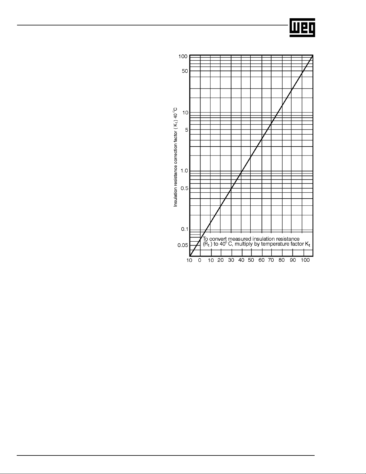
In case the test is carried out at a temperature other than 40°C, the
value must be corrected to 40°C using an approximated curve of
insulation resistance v.s temperature of the winding with the aid of
Figure 2.1; it’s possible verify that resistance practically doubles
every 10°C that insulating temperature is lowered.
5
Page 5
INSTALLA TION AND MAINTENANCE MANUAL
FOR NEMA LOW VOL T AGE ELECTRIC MOTORS
Example:
Ambient temperature = 50°C
Motor winding resistence at 50°C = 1.02 MΩ
Correction to 40°C
R
= R
40°C
R
= 1.02 x 1.3
40º C
R
40º C
x K
50°C
= 1.326 MΩ
50°C
The minimum resistence Rm will be:
Rm = Vn + 1
Rm = 0.440 + 1
Rm = 1.440 MΩ
On new motors, lower values are often attained due to solvents present
in the insulating varnishes that later evaporate during normal operation.
This does not necessarily mean that the motor is not operational,
since insulating resistance will increase after a period of service.
On motors which have been in service for a period of time much
larger values are often attained. A comparison of the values recorded
in previous tests on the same motor under similar load, temperature
and humidity conditions, serves as a better indication of insulation
condition than that of the value derived from a single test. Any substantial
or sudden reduction is suspect and the cause determined and
corrective action taken.
Insulation resistance is usually measured with a MEGGER.
In the event that insulation resistance is inferior to the values derived
from the above formula, motors should be subjected to a drying process.
2.3.1 Drying the windings
This operation should be carried out with maximum care, and only by
qualified personnel. The rate of temperature rise should not exceed
5°C per hour and the temperature of the winding should not exceed
105°C. An overly high final temperature as well as a fast temperature
increase rate can each generate vapour harmful to the insulation.
T emperature should be accurately controlled during the drying process
and the insulation resistance measured at regular intervals.
During the early stages of the drying process, insulation resistance
will decrease as a result of the temperature increase, but the resistance
will increase again when the insulation becomes dryer.
The drying process should be extended until sucessive measurements
of insulation resistance indicate that a constant value above the minimum
acceptable value has been attained. It is extremely important that the
interior of the motor be well ventilated during the drying operation to
ensure that the dampness is really removed.
Heat for drying can be obtained from outside sources (an oven),
energization of the space heater (optional), or introducing a current
through the actual winding of the motor being dried.
Figure 2.1
Winding T emperature (ºC)
R
= Rt x K
40 ºC
t 40 ºC
6
Page 6
3. Installation
INSTALLATION AND MAINTENANCE MANUAL
FOR NEMA LOW VOLTAGE ELECTRIC MOTORS
Electric machines should be installed in order to allow an easy access
for inspection and maintenance. Should the surrounding atmosphere
be humid, corrosive or contain flammable substances or particles, it is
essential to ensure an adequate degree of protection.
The installation of motors in environments where there are vapours,
gases or dusts, flammable or combustible materials, subject to fire or
explosion, should be undertaken according to appropriate and
governing codes, such as NEC Art. 500 (National Electrical Code)
and UL-674 (Underwriters Laboratories, Inc.) Standards.
Under no circumstances can motors be enclosed in boxes or covered
with materials which may impede or reduce the free circulation of
ventilating air. Machines fitted with external ventilation should be at
least 50cm from the wall to permit the passage of air.
The opening for the entry and exit of air flow should never be
obstructed or reduced by conductors, pipes or other objects.
The place of installation should allow for air renewal at a rate of 700
cubic feet per minute for each 75 HP motor capacity .
3.1 Mechanical Aspect s
3.1.1 Foundation
The motor base must be levelled and as far as possible free of
vibrations. A concrete foundation is recommended for motors over
100 HP . The choice of base will depend upon the nature of the soil at
the place of erection or of the floor capacity in the case of buildings.
When dimensioning the motor base, keep in mind that the motor may
occasionally be run at a torque above that of the rated full load torque.
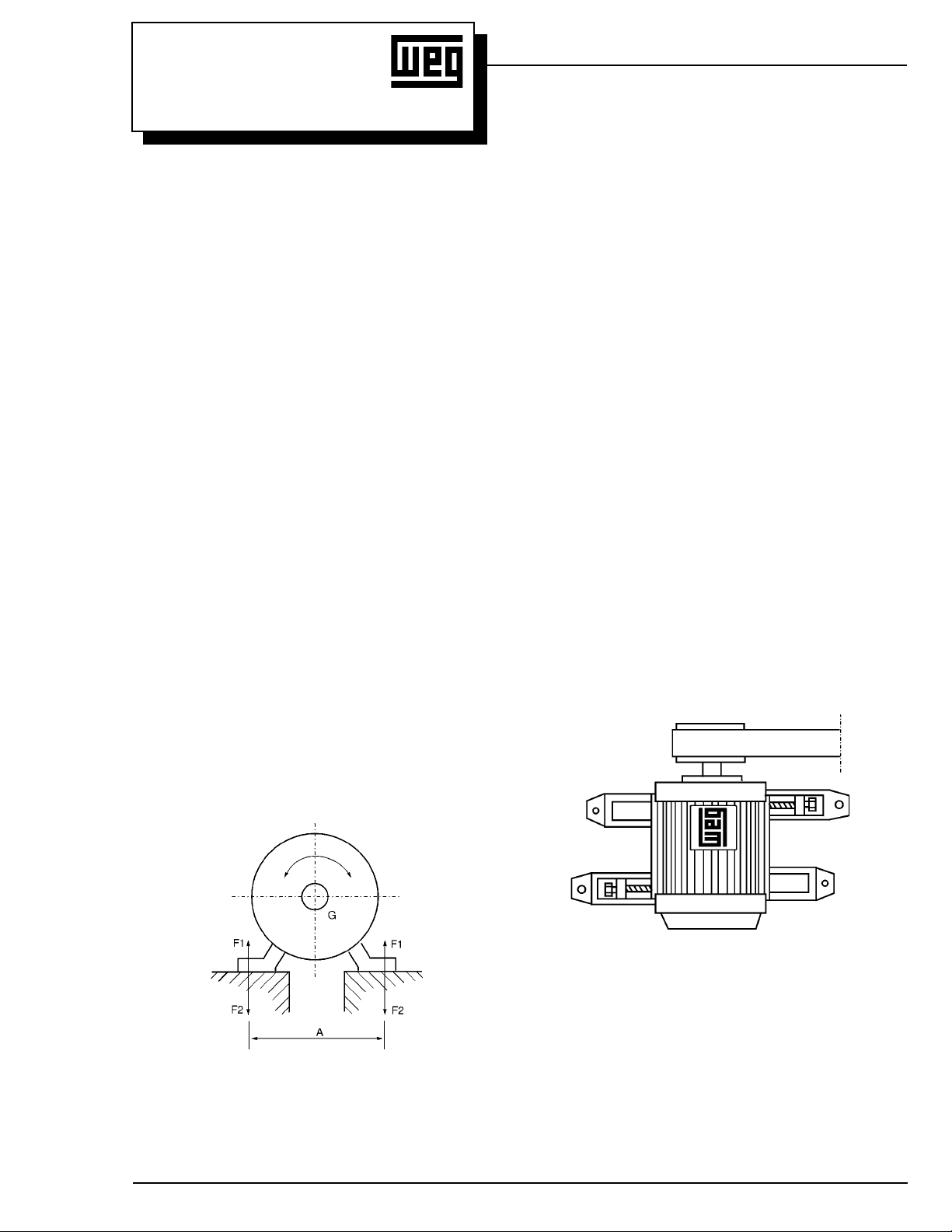
Based upon Figure 3.1, foundation stresses can be calculated by
using the following formula:
Where:
F1 and F2 - Lateral stress (Lb)
g - Force of gravity (32.18 ft/s2)
G - Weight of motor (Lb)
Tmax - Maximum torque (Lb . Ft)
A - Obtained from the dimensional drawing of the motor (in)
Sunken bolts or metallic base plates should be used to secure the
motor to the base.
3.1.2 Types of Bases
a) Slide Rails
When motor drive is by pulleys the motor should be mounted on
slide rails and the lower part of the belt should be pulling.
The rail nearest the drive pulley is positioned in such a manner that
the adjusting bolt be between the motor and the driven machine.
The other rail should be positioned with the bolt in the opposite
position, as shown in Figure 3.2.
The motor is bolted to the rails and set on the base. The drive
pulley is aligned such that its center is on a plane with the center of
the driven pulley and the motor shaft and that of the machine be
parallel.
The belt should not be overly stretched, see Figure 3.11.
After the alignment, the rails are fixed.
F1 = 0.2247 (0.009 x g x G - 213 Tmáx/A)
F2 = 0.2247 (0.009 x g x G + 213 Tmax/A )
Figure 3.1 - Base stresses
Figure 3.2 - Positioning of slide rails for motor alignment
7
Page 7
INSTALLA TION AND MAINTENANCE MANUAL
FOR NEMA LOW VOL T AGE ELECTRIC MOTORS
b) Foundation Studs
Very often, particularly when drive is by flexible coupling the motor is
anchored directly to the base with foundation studs.
It is recommended that shim plates of approximately 0.8 inches be
used between the foundation studs and the feet of the motor for
replacement purposes. These shim plates are useful when exchanging
one motor for another of larger shaft height due to variations allowed
by standard tolerances.
Foundation studs should neither be painted nor rusted as both interfere
with to the adherence of the concrete, and bring about loosening.
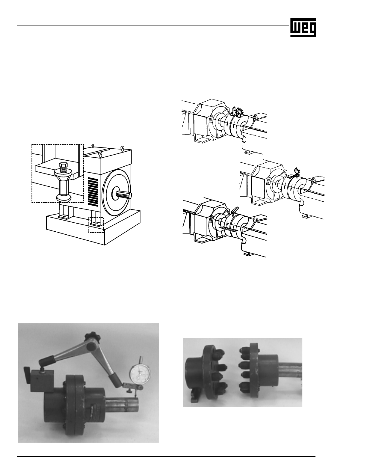
After accurate alignment and levelling of the motor, the foundation
studs are cemented and their screws tightened to secure the motor.
Thus, simultaneous readings are possible and allow for checking for
any parallel (Figure 3.6a) and concentricity deviations (Figure 3.6b)
by rotating the shafts one turn.
Gauge readings should not exceed 0.02 inches. If the installer is
sufficiently skilled, he can obtain alignment with feeler gauges and a
steel ruler, providing that the couplings are perfect and centered Figure 3.6c.
Figure 3.6a - Deviation
from parallel
Figure 3.6b - Deviation from
concentricity
Figure 3.3 - Motor mounted on a concrete base with foundation
studs
3.1.3 Alignment
The electric motor should be accurately aligned with the driven
machine, particularly in cases of direct coupling. An incorrect alignment
can cause bearing failure vibrations and even shaft rupture.
The best way to ensure correct alignment is to use dial gauges placed
on each coupling half, one reading radially and the other exially Figure 3.5.
Figure 3.6c - Alignment
with a steel ruler
3.1.4 Coupling
a) Direct Coupling
Direct coupling is always preferable due to its lower cost, space
economy, no belt slippage and lower accident risk.
In the case of speed ratio drives, it is also common to use a direct
coupling with a reducer (gear box).
CAUTION: Carefully align the shaft ends using, whenever feasible, a
flexible coupling.
Figure 3.5 - Alignment with dial gauges
8
Figure 3.7 - A type of direct coupling
b) Gear Coupling
Poorly aligned gear couplings are the cause of jerking motions which
bring about the vibration of the actual drive and vibrations within the
motor.
Page 8

INSTALLATION AND MAINTENANCE MANUAL
FOR NEMA LOW VOLTAGE ELECTRIC MOTORS
Therefore, due care must be given to perfect shaft alignment: exactly
parallel in the case of straight gears, and at the correct angle for bevel
or helical gears.
Perfect gear engagement can be checked by the insertion of a strip of
paper on which the teeth marks will be traced after a single rotation.
c) Belt and Pulley Coupling
Belt coupling is most commonly used when a speed ratio is required.
Assembly of Pulleys: T o assemble pulleys on shaft ends with a keyway
and threaded end holes the pulley should be inserted halfway up the
keyway merely by manual pressure.
On shafts without threaded end holes the heating of the pulley to about
80°C is recommended, or alternatively, the devices illustrated in Figure
3.8 may be employed.
Figure 3.8 - Pulley mounting device
RUNNING: To avoid needless radial stresses on the bearings it is
imperative that shafts are parallel and the pulleys perfectly aligned.
(Figure 3.10).
Figure 3.10 - Correct pulley alignment
Laterally misaligned pulleys, when running, transmit alternating knocks
to the rotor and can damage the bearing housing. Belt slippage can
be avoided by applying a resin (rosin for example).
Belt tension should be sufficient to avoid slippage during operation
(Figure 3.11).
Pulleys that are too small should be avoided; these cause shaft flexion
because belt traction increases in proportion to a decrease in the
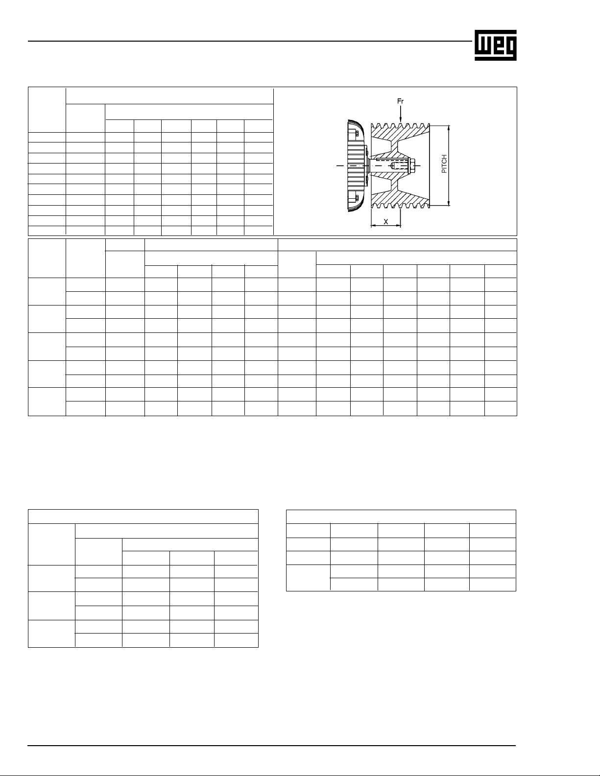
pulley size. T able 1 determines minimum pulley diameters, and T ables
2 and 3 refer to the maximum stresses acceptable on motor bearings
up to frame 580. Beyond frame size 600, an analysis should be
requested from the WEG engineering.
Figure 3.8a - Pulley extractor
Hammers should be avoided during the fitting of pulleys and
bearings. The fitting of bearings with the aid of hammers leaves
blemishes on the bearing races. These initially small flaws increase
with usage and can develop to a stage that completely impairs the
bearing.
The correct positioning of a pulley is shown in Figure 3.9.
Figure 3.9 - Correct positioning of pulley on the shaft
Figure 3.1 1 - Belt tensions
9
Page 9
INSTALLA TION AND MAINTENANCE MANUAL
FOR NEMA LOW VOL T AGE ELECTRIC MOTORS
T able 1 - Minimum pitch diameter of pulleys
Ball bearings
Frame Size X Inches
140 6205-Z 1.7 1.85 2
W 180 6206-Z 3.03 3.23 3.46
180 6307-Z 1.69 1.81 1.93
W 210 6308-Z 2.86 3.00 3.16
210 6308-Z 2.90 3.06 3.22
W 250 6309 C3 4.37 4.54 4.72 4.92
25 0 6309 C3 4.41 4.59 4.77 4.97
280 6311 C3 5.08 5.19 5.47 5.65
32 0 6312 C3 7.44 7.76 7.94 8.18
36 0 6314 C3 8.73 9.00 9.28 9.57
Frame Poles Size X Inches Size X Inches
400
440
500
5008
580
Bearing
II 6314 C3 7.3 7.62 7.94 8.24 - - - - - -
IV-VI-VII 6314 C3 NU 316 4.13 4.31 4.49 4.67 4.85 -
II 6314 C3 1 1.75 12.16 12.61 13.08 - - - - - -
IV-VI-VIII 6319 C3 NU 319 4.02 4.17 4.32 4.47 4.62 4.82
II 6314 C3 23.54 24.34 25.12 25.87 - - - - - -
IV-VI-VIII 6319 C3 NU 319 6.52 6.73 6.95 7.17 7.39 7.67
II 6314 C3 44.66 45.79 46.98 48.23 - - - - - -
IV-VI-VIII 6322 C3 NU 322 8.73 8.95 9.96 11.34 12.87 14.82
II 6314 C3 5 7 5 8 5 9 6 0 - - - - - -
IV-VI-VIII 6322 C3 NU 322 10.72 10.91 11.1 1 11.31 11.50 1 1.76
0.79 1.57 2.36 3.15 3.94 4.72
Ball Bearing Roller Bearing
Bearing Bearing
1.97 3.15 4.33 5.51 1.97 3.15 4.33 5.51 6.69 8.27
Important: 1) Peripheral speeds for solid grey cast iron pulleys FC 200 is V = 1 15 ft/s.
2) Use steel pulleys when peripheral speed is higher than 115 ft/s.
3) V-belt speed should not exceed 1 15 ft/s.
T able 2 - Maximum acceptable radial load (Lbf)
Nema 56 Motors Saw Arbor Motors
Radial Force (Lbf) 80 LMS II - 35 5 -
Frame Distance X 80 MMS II - 3 59 -
56A 90 LMS
56B
56D
Poles
II 88 - 59 II 427 -
IV 88 - 59 IV - 555 -
II 88 - 59
IV 86 - 59
II 127 - 70
IV 141 - 70
1 1,18 2 80 S MS I I - 357 -
10
Page 10
INSTALLATION AND MAINTENANCE MANUAL
FOR NEMA LOW VOLTAGE ELECTRIC MOTORS
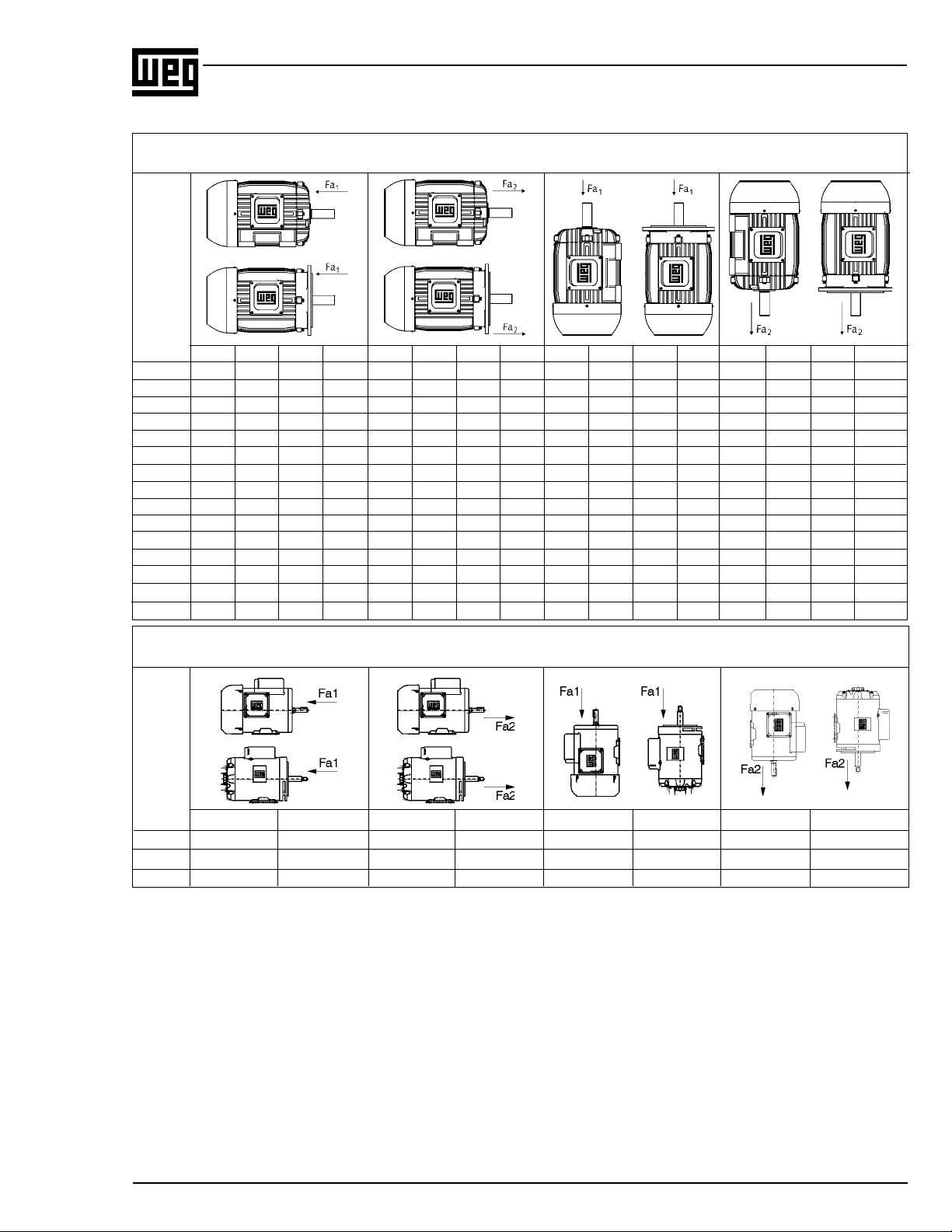
T able 3 - Maximum acceptable axial load (Lbf)
IP55 T otally Enclosed Motors - 60Hz
Position / Construction Form
F
R
A
M
E
II IV VI VIII II IV VI VIII II IV VI VIII II IV VI VIII
140 103 141 167 187 112 152 185 207 99 132 158 178 105 143 174 198
W 180 108 145 180 202 154 209 255 286 94 130 165 183 141 194 240 269
180 149 207 249 286 269 370 443 500 136 189 229 266 253 352 421 480
W 210 196 264 326 368 329 447 544 610 176 238 297 339 310 421 518 582
210 189 257 315 357 324 443 533 599 160 220 275 310 295 405 493 553
W 250 282 372 443 485 471 620 734 811 240 317 394 414 430 564 685 743
250 273 368 436 485 463 615 727 813 220 310 379 421 410 557 672 749
280 355 480 551 624 621 826 959 1,082 275 388 427 502 540 736 838 961
320 374 498 588 668 703 930 1,091 1,232 266 366 432 511 597 793 937 1,078
360 890 1,181 1,144 1,323 890 1,181 1,375 1,552 745 985 1,144 1,323 745 985 1,144 1,323
400 877 1,148 1,347 1,521 877 1,148 1,347 1,521 705 890 1,060 1,241 705 890 1,060 1,241
440 842 1,303 1,563 1,821 842 1,303 1,563 1,821 568 884 1,109 1,488 568 884 1,109 1,488
500 769 1,250 1,481 1,728 769 1,250 1,481 1,728 355 721 844 1,190 355 721 844 1,109
5008 791 1624 1909 2137 791 1624 1909 2137 728 1548 1808 2029 728 1548 1808 2029
580 679 1,406 1,649 1,865 679 1,406 1,649 1,865 033 474 549 597 033 474 549 597
Open Motors - NEMA 56 Frames - 60Hz
Position / Construction Form
F
R
A
M
E
II IV II IV II IV II IV
56 A 68 90 83 112 63 85 79 108
56 B 66 90 81 110 63 83 77 105
56 D 63 88 105 145 59 81 101 138
11
Page 11

INSTALLA TION AND MAINTENANCE MANUAL
FOR NEMA LOW VOL T AGE ELECTRIC MOTORS
The maximum radial load for each frame are determined, by graphs.
INSTRUCTIONS ON HOW TO USE THE GRAPHS
1 - Maximum radial load on shaft.
2 - Maximum radial load on bearings.
Where: X - Half of pulley width (inches)
Fr- Maximum radial load in relation to the diameter and
pulley width.
Example:
Verify whether a 2HP motor , II Pole, 60Hz withstands a radial load of
110Lb, considering a pulley width of 4 inches.
Frame: 145T
Fr: 110Lb
X: 2 inches
1 - Mark the distance X
2 - Find out line N = 3600 for bearing
Based on the above, this bearing withstands a radial load of 130Lb.
12
Page 12

INSTALLATION AND MAINTENANCE MANUAL
FOR NEMA LOW VOLTAGE ELECTRIC MOTORS
13
Page 13

INSTALLA TION AND MAINTENANCE MANUAL
FOR NEMA LOW VOL T AGE ELECTRIC MOTORS
14
Page 14

INSTALLATION AND MAINTENANCE MANUAL
FOR NEMA LOW VOLTAGE ELECTRIC MOTORS
Note: For frames 600 and above, consult your engineering
representative.
15
Page 15

INSTALLA TION AND MAINTENANCE MANUAL
FOR NEMA LOW VOL T AGE ELECTRIC MOTORS
3.2 Electrical Aspects
3.2.1 Feed System
Proper electric power supply is very important. The choice of motor
feed conductors, whether branch or distribution circuits, should be
based on the rated current of the motors as per NFPA-70 Standard
article 430.
T ables 4, 5 and 6 show minimum conductor gauges sized
according to maximum current capacity and maximum voltage drop
in relation to the distance from the distribution center to the motor,
and to the type of installation (Overhead or in ducts).
To determine the conductor gauge proceed as follows:
a) Determine the current by multiplying the current indicated on the
motor nameplate by 1.25 and then locate the resulting value on the
corresponding table.
If the conductor feeds more than one motor, the value to be sought
on the table should be equal 1.25 times the rated current of the
largest motor plus the rated current of the other motors.
In the case of variable speed motors, the highest value among the
rated currents should be considered.
When motor operation is intermittent, the conductors should have a
current carrying capacity equal or greater, to the product of the
motor rated current times the running cycle factor shown on T able
7.
T able 7 - Running cycle factor
Motor Short
Motor short
Duty
Classification
Short (operating valves,
activating contacts etc)
Intermittent (passenger or
freight elevators, tools,
pumps, rolling bridges etc)
Cyclic (rolling mills,mining
machines etc)
Variable
time rating
5min 15min
1.10
0.85
0.85
1.10
30 at
60min
1.50
1.20
0.85
0.90
0.90 0.95
1.20 1.50
Continuos
-
1.40
1.40
2.00
3.2.2 Starting of Electric Motor
Induction motors can be started by the following methods:
Direct Starting
Whenever possible a three-phase motor with a squirrel cage rotor
should be started directly at full supply voltage by means of a
contactor (Connection diagram a). This method is called Direct-onLine (DOL) starting.
There are DOL starter assemblies available combining a three-pole
contactor, a bimetal relay (overload protection device), and a fuse
(short circuit protection on branch circuit).
DOL starting is the simplest method, only feasible however , when the
locked rotor current (LRC) does not influence the main electric supply
lines.
Initial locked rotor current (LRC) in induction motors reach values six
to eight times the value of the full load current. During starting by the
DOL method, starting current can reach these high levels. The main
electrical supply should be rated sufficiently, such that during the starting
cycle no supply disturbance to others on the power network is caused
by the voltage drop in the main supply.
This can be achieved under one of the following situations:
a) The rated main supply current is high enough for the locked rotor
current not to be proportionally high.
b) Motor locked rotor current is low with no effect on the networks.
c) The motor is started under no-load conditions with a short starting
cycle and, consequently, a low locked rotor current with a transient
voltage drop tolerable to other consumers.
Starting with a compensating switch
(auto-transformer starting)
Should direct on line starting not be possible, either due to restrictions
imposed by the power supply authority or due to the installation itself,
reduced voltage indirect starting methods can be employed to lower
the locked rotor current. The single line connection diagram (C) shows
the basic components of a compensating switch featuring a transformer
(usually an auto-transformer) with a series of taps corresponding to
the different values of the reduced voltage. Only three terminals of the
motor are connected to the switch, the other being interconnected as
per diagram, for the indicated voltage.
Star-Delta starting
It is fundamental to star-delta starting that the three-phase motor has
the necessary numbers of leads for both connections:
b) Locate the rated voltage of the motor and the feed network
distance in the upper part of the corresponding table. The point of
intersection of the distance column and the line referring to current
will indicate the minimum required gauge of the conductor.
Example:
Size the conductors for a 15 HP , three-phase, 230V , 42A, motor
located 200 feet from the main supply with cables laid in conduits.
a) Current to be located: 1.25 x 42A = 52.5A
b) Closest value on table 6:55A
c) Minimum gauge: 6 A WG
16
6 leads for Y/∆
or 12 leads for YY/∆∆
All the connections for the various voltages are made through terminals
in the terminal box in accordance with the wiring diagram that
accompanies the motor. This diagram may be shown on the nameplate
or in the terminal box.
The star-delta connection is usually used only in low-voltage motors
due to normally available control and protection devices. In this
method of starting the locked rotor current is approximately 30% of
the original LRC. The locked rotor torque is reduced proportionally
as well. For this reason, it is very important before deciding to use
Page 16

INSTALLATION AND MAINTENANCE MANUAL
FOR NEMA LOW VOLTAGE ELECTRIC MOTORS
T able 4 - Wire and cable gauges for single-phase motor installation (voltage drop < 5%) (in conduits)
Supply Voltage Distance of motor from distribution centre (feet)
115 34 51 69 85 102 137 171 205 240 273 308 342 428 514
230 69 102 138 170 204 274 342 410 480 546 616 684 856 1028
460 138 204 276 340 408 548 684 820 960 1092 1232 1368 1712 2056
575 170 250 338 420 501 670 840 1010 1181 1342 1515 1680 2105 2530
Current ( A) Cable gauge (conductor)
5 14141414141414121212121010 8
10 14 14 14 14 12 12 10 10 10 8 8 8 6 6
15 12 12 12 12 12 10 8 8 6 6 6 6 4 2
20 121212101088666444 2
30 10101088666442221/0
40 8888664422221/02/0
55 6666644221/01/01/01/02/0
70 444442221/01/02/02/02/02/0
95 2222221/01/01/02/03/03/04/0250M
T able 5 - Wire and cable gauges for three-phase motor installation - aerial conductors with 25cm spacing (voltage drop < 5%)
Supply Voltage Distance of motor from distribution centre (feet)
115 51 69 85 102 137 171 205 240 273 308 342 428 514 685
230 102 138 170 204 274 342 410 480 546 616 684 856 1028 1370
460 204 276 340 408 547 684 820 960 1092 1232 1368 1712 2056 2740
575 250 338 420 501 670 840 1010 1181 1342 1515 1680 2105 2530 3350
Current ( A) Cable gauge (conductor)
15 14 14 14 12 12 10 10 10 8 8 8 6 6 4
20 14 14 12 12 10 10 8 8 8 6 6 4 4 2
30 14121088866444221/0
40 1210108864442221/02/0
55 1010886442221/02/03/0--
70 886642221/01/02/03/0---100 6644221/02/03/04/04/0-----130 44421/01/02/04/0---------- -175 2 2 2 1/0 2/0 3/0 -- -- -- -- -- -- -- -225 1/0 1/0 1/0 2/0 3/0 -- -- -- -- -- -- -- -- -275 2/0 2/0 2/0 4/0 -- -- -- -- -- -- -- -- -- -320 3/0 3/0 3/0 4/0 -- -- -- -- -- -- -- -- -- --
T able 6 - Wire and cable gauges for three-phase motor installation (voltage drop < 5%) (in conduits)
Supply Voltage Distance of motor from distribution centre (feet)
115 85 102 120 137 171 205 240 273 308 342 428 514
230 170 204 240 274 342 410 480 546 616 684 856 1028
460 340 408 480 548 684 820 960 1092 1232 1368 1712 2056
575 420 501 590 670 840 1010 1181 1342 1515 1680 2105 2530
Current ( A) Cable gauge (conductor)
15 12121210108 886664
20 1210101088 666644
30 1088866 644422
40 886664 442221/0
55 6 6 6 4 4 4 2 2 2 1/0 1/0 1/0
70 4 4 4 4 2 2 2 1/0 1/0 1/0 2/0 2/0
95 2 2 2 2 2 1/0 1/0 1/0 1/0 2/0 3/0 4/0
125 1/0 1/0 1/0 1/0 1/0 1/0 2/0 2/0 3/0 3/0 4/0 250M
145 2/0 2/0 2/0 2/0 2/0 2/0 2/0 3/0 3/0 4/0 250M 300M
165 3/0 3/0 3/0 3/0 3/0 3/0 3/0 3/0 4/0 4/0 250M 350M
195 4/0 4/0 4/0 4/0 4/0 4/0 4/0 4/0 250M 250M 300M 350M
215 250M 250M 250M 250M 250M 250M 250M 250M 250M 300M 350M 400M
240 300M 300M 300M 300M 300M 300M 300M 300M 300M 300M 400M 500M
265 350M 350M 350M 350M 350M 350M 350M 350M 350M 350M 500M 500M
280 400M 400M 400M 400M 400M 400M 400M 400M 400M 400M 400M -320 500M 500M 500M 500M 500M 500M 500M 500M 500M 500M 500M --
Note: The above indicated values are orientative. For guaranteed values, contact the Local Power Company.
17
Page 17

INSTALLA TION AND MAINTENANCE MANUAL
FOR NEMA LOW VOL T AGE ELECTRIC MOTORS
star-delta starting to verify if the reduced locked rotor torque in “STAR”
connection is enough to accelerate the load.
3.2.3 Motor Protection
Motor circuits have, in principle, two types of protection: motor overload,
locked rotor and protection of branch circuit from short circuits. Motors
in continuous use should be protected from overloading by means of
a device incorporated into the motor, or by an independent device,
usually a fixed or adjustable thermal relay equal or less than to the
value derived from multiplying the rated feed current at full load by:
- 1.25 for motors with a service factor equal or superior to 1.15 or;
- 1.15 for motors with service factor equal to 1.0.
Some motors are optionally fitted with overheating protective detectors
(in the event of overload, locked rotor, low voltage, inadequate motor
ventilation) such as a thermostat (thermal probe), thermistor (PTC),
RTD type resistance which dispense with independent devices.
THERMOSTA T (THERMAL PROBE): Bimetallic thermal detectors
with normally closed silver contacts. These open at pre-determined
temperatures. Thermostats are series connected directly to the
contactor coil circuit by two conductors.
THERMISTORS: Semi-conductor heat detectors positive temperature
coeficient (PTC) that sharply change their resistance upon reaching
a set temperature. Thermistors, depending upon the type, are series
or parallel-connected to a control unit that cuts out the motor feed, or
actuates an alarm system, in response to the thermistors reaction.
RESISTANCE TEMPERATURE DETECT ORS (RTD) - PT 100:The
resistance type heat detector (RTD) is a resistance element usually
manufactured of copper or platinum.
The RTD operates on the principle that the electrical resistance of a
metallic conductor varies linearly with the temperature. The detector
terminals are connected to a control panel, usually fitted with a
temperature gauge, a test resistance and a terminal changeover
switch.
Subject to the desired degree of safety and the client’s specification,
three (one per phase) or six (two per phase) protective devices can
be fitted to a motor for the alarm stems, circuit breaker or combined
alarm and circuit breaker, with two leads from the terminal box to the
alarm or circuit breaker system and four for the combined system
(alarm and circuit breaker).
T able 9 compares the two methods of protection.
3.3 Start-up
3.3.1 Preliminary Inspection
Before starting a motor for the first time, it will be necessary to:
c) Ascertain that voltage and frequency correspond to those indicated
on the nameplate. Motor performance will be satisfactory with main
supply voltage fluctuation within ten per cent of the value indicated
on the nameplate or a frequency fluctuation within five per cent or,
yet, with a combined voltage and frequency variance within ten
per cent;
d) Check that connections are in accordance with the connection
diagram shown on the nameplate and be sure that all terminal
screws and nuts are tight;
e) Check the motor for proper grounding. Providing that there are no
specifications calling for ground-insulated installation, the motor
must be grounded in accordance with prevalent standard for
grounding electrical machines. The screw identified by the symbol
should be used for this purpose.
This screw is generally to be found in the terminal box or on one
foot of the frame;
f) Check that motor leads connecting with the mains, as well as the
control wires and the overload protection device, are in accordance
with Nema Standards;
g) If the motor has been stored in a damp place, or has been stopped
for some time, measure the insulating resistance as recommended
under the item covering storage instructions;
h) Start the motor uncoupled to ascertain that it is turning in the desired
direction. To reverse the rotation of a three-phase motor , invert
two terminal leads of the mains supply.
High voltage motors bearing an arrow on the frame indicating
rotation direction can only turn in the direction shown.
3.3.2 The First Start-up
Three-Phase Motor with Cage Rotor:
After careful examination of the motor, follow the normal sequence of
starting operations listed in the control instructions for the initial startup.
3.3.3 Operation
Drive the motor coupled to the load for a period of at least one hour
while watching for abnormal noises or signs of overheating.
Compare the line current with the value shown on the nameplate.
Under continuous running conditions without load fluctuations this
should not exceed the rated current times the service factor, also
shown on the nameplate.
All measuring and control instruments and apparatus should be
continuously checked for anomalies, and any irregularities corrected.
a) Remove all locking devices and blocks used in transit and check
that the motor rotates freely;
b) Check that the motor is firmly secured and that coupling elements
are correctly mounted and aligned.;
18
3.3.4 Stopping
Warning:
To touch any moving part of a running motor, even though
Page 18

INSTALLATION AND MAINTENANCE MANUAL
FOR NEMA LOW VOLTAGE ELECTRIC MOTORS
disconnected, is a danger to life and limb.
Three-phase motor with cage rotor:
Open the stator circuit switch. With the motor at a complete stop, reset
the auto-transformer, if any, to the “start” position.
Table 9 - Comparison between motor protection system
Current-based Protection
protection with
Causes of probe
overheating Fuse and thermistor
Fuse only thermal in motor
protector
1. Overload with 1.2
times rated current
2. Duty cycles
S1 to S8
IEC 34, EB 120
Caption: unprotected
partially protected
totally protected
3. Brakings, reversals
and frequent starts
4. Operating with more
than 15 starts p/hour
5. Locked rotor
6. Fault on one phase
7. Execessive voltage
fluctuation
8. Frequency fluctuation
on main supply
9. Excessive ambient
temperature
10. External heating
caused by bearings,
belts, pulleys etc.
11. Obstructed ventilation
19
Page 19

INSTALLA TION AND MAINTENANCE MANUAL
FOR NEMA LOW VOL T AGE ELECTRIC MOTORS
CONNECTION DIAGRAMS
a) Direct starting
POWER NETWORK
b) Star-Delta starting
POWER NETWOR
c) Auto-transformer starting
POWER NETWORK
20
Page 20

T able 1 1 - Bearing specifications by type of motor
INSTALLATION AND MAINTENANCE MANUAL
FOR NEMA LOW VOLTAGE ELECTRIC MOTORS
NEMA Bearings
Frames Front (D.E.) Rear (O.D.E.)
B48 and C48 6203 Z 6202 Z
56 and A56 6203 Z 6202 Z
B56 and C56 6203 Z 6202 Z
D56 and 6204 Z 6202 Z /
F56H/G56H 6203 Z
143 T 6205 ZZ 6204 ZZ
145 T 6205 ZZ 6204 ZZ
182 T 6307 ZZ 6206 ZZ
184 T 6307 ZZ 6206 ZZ
W 182 T 6206 ZZ 6205 ZZ
W 184 T 6206 ZZ 6205 ZZ
213 T 6308 ZZ 6207 ZZ
215 T 6308 ZZ 6207 ZZ
W 213 T 6308 ZZ 6207 ZZ
W 215 T 6308 ZZ 6207 ZZ
254 T 6309-C3 6209 Z-C3
256 T 6309-C3 6209 Z-C3
W 254 T 6309-C3 6209 Z-C3
W 256 T 6309-C3 6209 Z-C3
284 T and TS 631 1-C3 621 1 Z-C3
286 T and TS 631 1-C3 621 1 Z-C3
324 T and TS 6312-C3 6212 Z-C3
326 T and TS 6312-C3 6212 Z-C3
364 T and TS 6314-C3 6314-C3
365 T and TS 6314-C3 6314-C3
404 T NU 316-C3 6314-C3
404 TS 6314-C3 6314-C3
405 T NU 316-C3 6314-C3
405 TS 6314-C3 6414-C3
444 T NU 319-C3 6316-C3
444 TS 6314-C3 6314-C3
445 T NU 319-C3 6316-C3
445 TS 6314-C3 6314-C3
447 T NU 319-C3 6316-C3
447 TS 6314-C3 6314-C3
449 T NU 322-C3 6319-C3
449 TS 6314-C3 6314-C3
504 T NU 319-C3 6316-C3
504 TS 6314-C3 6314-C3
505 T NU 319-C3 6316-C3
505 TS 6314-C3 6314-C3
5008 T NU 322-C3 6319-C3
5008TS 6314-C3 6314-C3
586 T NU 322-C3 6319-C3
586 TS 6314-C3 6314-C3
587 T NU 322-C3 6319-C3
587 TS 6314-C3 6314-C3
Saw Arbor Bearings
motor Mounting
frame Front (D.E.) Rear (O.D.E.)
80 S M S 6307 ZZ 6207 ZZ
80 M M S 6307 ZZ 6207 ZZ
80 L MS 6307 ZZ 6207 ZZ
90 L MS 6308 ZZ 6208 ZZ
Mounting
Open drip proof motors
ALL FORMS
T otally enclosed fan cooled motors
ALL FORMS
B3
ODP Motors Bearings
Nema-T Mounting
frames Front (D.E.) Rear (O.D.E.)
E143/5T 6205 ZZ 6204 ZZ
F143/5T 6205 ZZ 6204 ZZ
182 T 6206 ZZ 6205 ZZ
184 T 6202 ZZ 6205 ZZ
213/5T 6208 ZZ 6206 ZZ
254 T 6309 Z-C3 6209 Z-C3
256 T 6309 Z-C3 6209 Z-C3
284 T 6311 Z-C3 6211 Z-C3
284 TS 6311 Z-C3 6211 Z-C3
286 T 6311 Z-C3 6211 Z-C3
286 TS 6311 Z-C3 6211 Z-C3
324 T 6312 Z-C3 6212 Z-C3
324 TS 6312 Z-C3 6212 Z-C3
326 T 6312 Z-C3 6212 Z-C3
326 TS 6312 Z-C3 6212 Z-C3
364 T 6314 C3 6314 C3
364 TS 6314 C3 6314 C3
365 T 6314 C3 6314 C3
365 TS 6314 C3 6314 C3
404 T NU 316 C3 6314 C3
404 TS 6314 C3 6314 C3
405 T NU 316 C3 6314 C3
405 TS 6314 C3 6314 C3
444 T NU 319 C3 6316 C3
444 TS 6314 C3 6314 C3
445 T NU 319 C3 6316 C3
445 TS 6314 C3 6314 C3
IEC Bearings
frame Front (D.E.) Rear (O.D.E.)
63 6201 ZZ 6201 ZZ
71 6203 ZZ 6202 ZZ
80 6204 ZZ 6203 ZZ
90 S - L 6205 ZZ 6204 ZZ
100 L 6206 ZZ 6205 ZZ
112 M 6307 ZZ 6206 ZZ
132 S - M 6308 ZZ 6207 ZZ
160 M - L 6309-C3 6209 Z-C3
180 M - L B3 6311-C3 6211 Z-C3
200 M - L 6312-C3 6212 Z-C3
225 S/M 6314-C3 6314-C3
250 S/M 6314-C3 6314-C3
280 S/M 6314-C3 6314-C3
315 S/M 6314-C3 6314-C3
355 M/L 6314-C3 6314-C3
HORIZONTAL MOUNTING ONLY
Mounting
T otally enclosed fan cooled motors
6316-C3 6316-C3
6319-C3 6316-C3
NU 322-C3 6319-C3
21
Page 21

INSTALLA TION AND MAINTENANCE MANUAL
FOR NEMA LOW VOL T AGE ELECTRIC MOTORS
T able 12 – Bearing lubrication intervals and amount of grease
BALL BEARINGS - Series 62/63
Relubrication intervals (running hours – horizontal position)
II pole IV pole VI pole VIII pole X pole XII pole
Serie 62
Bearing 60Hz 50Hz 60Hz 50Hz 60Hz 50Hz 60Hz 50Hz 60Hz 50Hz 60Hz 50Hz (g)
6209 18400 20000 20000 20000 20000 20000 20000 20000 20000 20000 20000 20000 9
6211 14200 16500 20000 20000 20000 20000 20000 20000 20000 20000 20000 20000 11
6212 12100 14400 20000 20000 20000 20000 20000 20000 20000 20000 20000 20000 13
Serie 63
Bearing 60Hz 50Hz 60Hz 50Hz 60Hz 50Hz 60Hz 50Hz 60Hz 50Hz 60Hz 50Hz (g)
6309 15700 18100 20000 20000 20000 20000 20000 20000 20000 20000 20000 20000 13
6311 11500 13700 20000 20000 20000 20000 20000 20000 20000 20000 20000 20000 18
6312 9800 11900 20000 20000 20000 20000 20000 20000 20000 20000 20000 20000 21
6314 3600 4500 9700 11600 14200 16400 17300 19700 19700 20000 20000 20000 27
6316 - - 8500 10400 12800 14900 15900 18700 18700 20000 20000 20000 34
6319 - - 7000 9000 11000 13000 14000 17400 17400 18600 18600 20000 45
6322 - - 5100 7200 9200 10800 11800 15100 15100 15500 15500 19300 60
Amount of
grease
Table 13 – Bearing lubrication intervals and amount of grease
BALL BEARINGS - Series NU3
Relubrication intervals (running hours – horizontal position)
II pole IV pole VI pole VIII pole X pole XII pole
Bearing 60Hz 50Hz 60Hz 50Hz 60Hz 50Hz 60Hz 50Hz 60Hz 50Hz 60Hz 50Hz (g)
NU 309 9800 13300 20000 20000 20000 20000 20000 20000 20000 20000 20000 20000 13
NU 311 6400 9200 19100 20000 20000 20000 20000 20000 20000 20000 20000 20000 18
NU 312 5100 7600 17200 20000 20000 20000 20000 20000 20000 20000 20000 20000 21
NU 314 1600 2500 7100 8900 11000 13100 15100 16900 16900 19300 19300 20000 27
NU 316 - - 6000 7600 9500 11600 13800 15500 15500 17800 17800 20000 34
NU 319 - - 4700 6000 7600 9800 12200 13700 13700 15700 15700 20000 45
NU 322 - - 3300 4400 5900 7800 10700 11500 11500 13400 13400 17300 60
NU 324 - - 2400 3500 5000 6600 10000 10200 10200 12100 12100 15000 72
Notes:
• The ZZ bearings from 6201 to 6307 do not require relubrication
as its life time is about 20,000 hours.
• Tables 1 and 2 are intended for the lubrication period under bearing
temperature of 70oC (for bearings up to 6312 and NU 312) and
temperature of 85oC (for bearings 6314 and NU 314 and larger).
• For each 15oC of temperature rise, the relubrication period is
reduced by half.
• The relubrication periods given above are for those cases applying
Polyrex® EM grease.
• When motors are used on the vertical position, their relubrication
interval is reduced by half if compared to horizontal position motors.
Compatibility of Polyrex® EM grease with other types of grease:
Containing polyurea thickener and mineral oil, the Polyrex® EM grease
is compatible with other types of grease that contain:
• Lithium base or complex of lithium or polyurea and highly refined
mineral oil.
• Inhibitor additive against corrosion, rust and anti-oxidant additive.
Notes:
• Although Polyrex® EM is compatible with types of grease given
above, we do no recommended to mix it with any other greases.
• If you intend to use a type of grease different than those recommended
above , first contact WEG.
• On applications (with high or low temperatures, speed variation,
etc), the type of grease and relubrification interval are given on an
additional nameplate attached to the motor.
Amount of
grease
22
Page 22

4. Maintenance
INSTALLATION AND MAINTENANCE MANUAL
FOR NEMA LOW VOLTAGE ELECTRIC MOTORS
A well-designed maintenance program for electric motors can be
summed up as: periodical inspection of insulation levels, temperature
rise, wear, bearing lubrication and the occasional checking of fan air
flow.
Inspection cycles depend upon the type of motor and the conditions
under which it operates.
4.1 Cleanliness
Motors should be kept clean, free of dust, debris and oil. Soft brushes
or clean cotton rags should be used for cleaning. A jet of compressed
air should be used to remove non-abrasive dust from the fan cover
and any accumulated grime from the fan and cooling fins.
Oil or damp impregnated impurities can be removed with rags soaked
in a suitable solvent.
T erminal boxes fitted to motors with IP55 protection should be cleaned;
their terminals should be free of oxidation, in perfect mechanical
condition, and all unused space dust-free.
Motors with IPW 55 protection are recommended for use under
unfavourable ambient conditions.
4.2 Lubrication
Proper lubrication extends bearing life.
Lubrication Maintenance Includes:
a) Attention to the overall state of the bearings;
b) Cleaning and lubrication;
c) Critical inspection of the bearings.
Motor noise should be measured at regular intervals of one to four
months. A well-tuned ear is perfectly capable of distinguishing unusual
noises, even with rudimentary tools such as a screw driver, etc.,
without recourse to sophisticated listening aids or stethescopes that
are available on the market.
A uniform hum is a sign that a bearing is running perfectly . Bearing
temperature control is also part of routine maintenance.
Constant temperature control is possible with the aid of external
thermometers or by embedded thermal elements. WEG motors are
normally equipped with grease lubricated ball or roller bearings.
Bearings should be lubricated to avoid metallic contact of the moving
parts, and also for protection against corrosion and wear. Lubricant
properties deteriorate in the course of time and mechanical operation:
furthermore, all lubricants are subject to contamination under working
conditions.
For this reason lubricants must be renewed and any lubricant
consumed needs replacing from time to time.
4.2.1 Periodical Lubrication
WEG motors are supplied with sufficient grease for a long running
period. Lubrication intervals, the amount of grease and the type of
bearing used in frames 140T to 580T are to be found in Tables 11, 12
and 13.
Lubrication intervals depend upon the size of the motor, speed, working
conditions and the type of grease used.
4.2.2 Quality and Quantity of Grease
Correct lubrication is important!
Grease must be applied correctly and in sufficient quantity as both
insufficient or excessive greasing are harmful.
Excessive greasing causes overheating brought about by the
greater resistance encountered by the rotating parts and, in
particular, by the compacting of the lubricant and its eventual loss of
lubricating qualities.
This can cause seepage with the grease penetrating the motor and
dripping on the coils.
GREASES FOR MOTOR BEARINGS
For operating temperatures from -30 to 170oC
Type
Polyrex® EM
Supplier
Esso
4.2.3 Lubricating Instructions
a) Frame 140T to 210T motors
Frame 140T to 210T size motors are not fitted with grease nipples.
Lubrication is carried out during periodical overhauls when the
motor is taken apart.
Cleaning and Lubrication of Bearings
With the motor dismantled and without extracting the bearings from
the shaft, all existing grease should be removed and the bearings
cleaned with Diesel oil, kerosene or other solvent, until thoroughly
clean.
Refill the spaces between the balls or rollers and the bearing cages
with grease immediately after washing. Never rotate bearings in their
dry state after washing.
For inspection purposes apply a few drops of machine oil. During
these operations maximum care and cleanliness is recommended to
avoid the penetration of any impurities or dust that could harm the
bearings. Clean all external parts prior to reassembly .
b) Frame 360T to 580T Motors
Motors above 360T frame size are fitted with regreasable bearing
system.
The lubrication system from this frame size upwards was designed to
allow the removal of all grease from the bearing races through a
bleeder outlet which at the same time impedes the entry of dust or
other contaminants harmful to the bearing.
This outlet also prevents injury to the bearings from the well-known
problem of over-greasing.
23
Page 23

INSTALLA TION AND MAINTENANCE MANUAL
FOR NEMA LOW VOL T AGE ELECTRIC MOTORS
It is advisable to lubricate while the motor is running, to allow the
renewal of grease in the bearing case.
Should this procedure not be possible because of rotating parts in the
proximity of the nipple (pulleys, coupling sleeves, etc.) that are
hazardous to the operator the following procedure should be followed:
- Inject about half the estimated amount of grease and run the motor at
full speed for approximately a minute; switch off the motor and inject
the remaining grease.
The injection of all the grease with the motor at rest could cause
penetration of a portion of the lubricant through the internal seal of the
bearing case and hence into the motor.
Providing suitable tooling is employed, disassembly of a bearing is
not difficult.
The extractor grips should be applied to the sidewall of the inner ring
to be stripped, or to an adjacent part.
To ensure perfect functioning and to prevent injury to the bearing
parts, it is essential that the assembly be undertaken under conditions
of complete cleanliness and by competent personnel.
New bearings should not be removed from their packages until the
moment of assembly.
Prior to fitting a new bearing, ascertain that the shaft has no rough
edges or signs of hammering.
Figure 4.1 - Bearings and lubrication system
Nipples must be clean prior to introduction of grease to avoid entry of
any alien bodies into the bearing.
For lubricating use only a manual grease gun.
Bearing Lubrication Steps
1.Cleanse the area around the grease nipples with clean cotton
fabric.
2.With the motor running, add grease with a manual grease gun until
the lubricant commences to be expelled from the bleeder outlet, or
until the quantity of grease recommended in T ables 12 or 13 has
been applied.
3.Allow the motor to run long enough to eject all excess grease.
4.2.4 Replacement of Bearings
The opening of a motor to replace a bearing should only be carried
out by qualified personnel.
Damage to the core after the removal of the bearing cover can be
avoided by filling the gap between the rotor and the stator with stiff
paper of a proper thickness.
Figure 4.2 - A bearing extractor
During assembly bearings cannot be subjected to direct blows.
The aid used to press or strike the bearing should be applied to the
inner ring.
4.3 Air Gap Checking (Large Rating Open
Motors)
Upon the completion of any work on the bearings check the gap
measurement between the stator and the rotor using the appropriate
gazes.
The gap variation at any two vertically opposite points must be less
than 10% of the average gap measurement.
4.4 Explosion Proof Motor Repair Steps
4.4.1 Objective
In view of the heavy liability associated with burning of motors of this
type, this product has been designed and manufactured to high
technical standards, under rigid controls. In addition, in many areas it
is required that explosion proof motors ONLY be repaired by licensed
personnel or in licensed facilities authorized to do this type of work.
The following general procedures, safeguards, and guidelines must
be followed in order to ensure repaired explosion proof motors operate
as intended.
4.4.2 Repair Procedure and Precautions
Dismantle the damaged motor with appropriate tools without hammering
and/or pitting machined surfaces such as enclosure joints, fastening
24
Page 24

INSTALLATION AND MAINTENANCE MANUAL
FOR NEMA LOW VOLTAGE ELECTRIC MOTORS
holes, and all joints in general.
The position of the fan cover should be suitably marked prior to
removal so as to facilitate reassembly later on.
Examine the motor’s general condition and, if necessary, disassemble
all parts and clean them with kerosene. Under no circumstances
should scrapers, emery papers or tools be used that could affect the
dimensions of any part during cleaning.
Protect all machined parts against oxidation by applying a coating of
vaseline or oil immediately after cleaning.
STRIPPING OF WINDINGS
This step requires great care to avoid knocking and/or denting of
enclosure joints and, when removing the sealing compound from the
terminal box, damage or cracking of the frame.
IMPREGNATION
Protect all frame threads by inserting corresponding bolts, and the
joint between terminal box and frame, by coating it with a non-adhesive
varnish (ISO 287 - ISOLASIL).
Protective varnish on machined parts should be removed soon after
treating with impregnating varnish. This operation should be carried
out manually without using tools.
ASSEMBLY
Inspect all parts for defects, such as cracks, joint incrustations, damaged
threads and other potential problems.
Assemble using a rubber headed mallet and a bronze bushing after
ascertaining that all parts are perfectly fitted.
Bolts should be positioned with corresponding spring washers and
evenly tightened.
• Upon reassembling explosion proof motors IPW55 the substitution
of all seals is mandatory.
• Should any doubts arise, consult WEG.
TESTING
Rotate the shaft by hand while examining for any drag problems on
covers or fastening rings.
Carry out running tests as for standard motors.
MOUNTING THE TERMINAL BOX
Prior to fitting the terminal box all cable outlets on the frame should be
sealed with a sealing compound (Ist layer) and an Epoxy resin (ISO
340) mixed with ground quartz (2nd layer) in the following proportions:
340A resin 50 parts
340B resin 50 parts
Ground quartz 100 parts
Drying time for this mixture is two hours during which the frame should
not be handled and cable outlets should be upwards.
When dry, see that the outlets and areas around the cables are
perfectly sealed.
Mount the terminal box and paint the motor.
4.4.3 Miscellaneous Recommendations
• Any damaged parts (cracks, pittings in machined surfaces,
defective threads) must be replaced and under no circumstances
should attempts be made to recover them.
25
Page 25

INSTALLA TION AND MAINTENANCE MANUAL
FOR NEMA LOW VOL T AGE ELECTRIC MOTORS
5. Malfunctioning
Most malfunctions affecting the normal running of electric motors can
be prevented by maintenance and the appropriate precautions.
While ventilation, cleanliness and careful maintenance are the main
factors ensuring long motor life, a further essential factor is the prompt
attention to any malfunctioning as signalled by vibrations, shaft knock,
declining insulation resistance, smoke or fire, sparking or unusual slip
ring or brush wear, sudden changes of bearing temperatures.
When failures of an electric or mechanical nature arise, the first step to
be taken is to stop the motor and subsequent examination of all
mechanical and electrical parts of the installation.
In the event of fire, the installation should be isolated from the mains
supply, which is normally done by turning of f the respective switches.
In the event of fire within the motor itself, steps should be taken to
restrain and suffocate it by covering the ventilation vents.
To extinguish a fire, dry chemical or C0
used - never water.
extinguishers should be
2
5.1 Standard Three-Phase Motor Failures
Owing to the widespread usage of asynchronous three-phase motors
in industry which are more often repaired in the plant workshops,
there follows a summary of possible failures and their probable causes,
detection and repairs.
Motors are generally designed to Class B or F insulation and for
ambient temperatures up to 40°C.
Most winding defects arise when temperature limits, due to current
overload, are surpassed throughout the winding or even in only
portions thereof. These defects are identified by the darkening or
carbonizing of wire insulation.
5.1.1 Short Circuits Between Turns
A short circuit between turns can be a consequent of two coinciding
insulation defects, or the result of defects arising simultaneously on
two adjacent wires. As wires are randomly tested, even the best
quality wires can have weak spots. Weak spots can, on occasion,
tolerate a voltage surge of 30% at the time of testing for shorting
between turns, and later fail due to humidity, dust or vibration.
Depending on the intensity of the short, a magnetic hum becomes
audible.
In some cases, the three-phase current imbalance can be so
insignificant that the motor protective device fails to react. A short circuit
between turns, and phases to ground due to insulation failure is rare,
and even so, it nearly always occurs during the early stages of
operation.
5.1.2 Winding Failures
a) One burnt winding phase
This failure arises when a motor runs wired in delta and current fails
in one main conductor.
Current rises from 2 to 2.5 times in the remaining winding with a
simultaneous marked fall in speed. If the motor stops, the current will
increase from 3.5 to 4 times its rated value.
In most instances, this defect is due to the absence of a protective
switch, or else the switch has been set too high.
b) Two burnt winding phases
This failure arises when current fails in one main conductor and the
motor winding is star-connected. 0ne of the winding phases remains
currentless while the others absorb the full voltage and carry an
excessive current.
The slip almost doubles.
c) Three burnt winding phases
Probable cause 1
Motor only protected by fuses; an overload on the motor will be the
cause of the trouble.
Consequently, progressive carbonizing of the wires and insulation
culminate in a short circuit between turns, or a short against the frame
occurs.
A protective switch placed before the motor would easily solve this
problem.
Probable cause 2
Motor incorrectly connected. For example: A motor with windings
designed for 230/400V is connected through a star-delta switch to
400V connection.
The absorted current will be so high that the winding will burn out in a
few seconds if the fuses or a wrongly set protective switch fail to react
promptly.
Probable cause 3
The star-delta switch is not commutated and the motor continues to
run for a time connected to the star under overload conditions.
As it only develops 1/3 of its torque, the motor cannot reach rated
speed. The increased slip results in higher ohmic losses arising from
the Joule effect. As the stator current, consistent with the load, may not
exceed the rated value for the delta connection, the protective switch
will not react.
Consequent to increased winding and rotor losses the motor will
overheat and the winding burn out.
Probable cause 4
Failures from this cause arise from thermal overload, due to too many
starts under intermittent operation or to an overly long starting cycle.
The perfect functioning of motor operating under these conditions is
only assured when the following values are heeded:
a) number of starts per hour;
b) starting with or without load;
c) mechanical brake or current inversion;
d) acceleration of rotating masses connected to motor shaft;
e) load torque vs. speed during acceleration and braking.
The continuous effort exerted by the rotor during intermittent starting
brings about heavier losses which provoke overheating.
Under certain circumstances with the motor idle there is a possibility
that the stator winding is subjected to damage as a result of the
26
Page 26

INSTALLATION AND MAINTENANCE MANUAL
FOR NEMA LOW VOLTAGE ELECTRIC MOTORS
heating of the motor. In such a case, a slip ring motor is recommended
as a large portion of the heat (due to rotor losses) is dissipated in the
rheostat.
5.1.3 Rotor Failures
If a motor running under load conditions produces a noise of varying
intensity and decreasing frequency while the load is increased, the
reason, in most cases, will be an unsymmetrical rotor winding.
In squirrel-cage motors the cause will nearly always be a break in
one or more of the rotor bars; simultaneously, periodical stator current
fluctuations may be recorded. As a rule, this defect appears only in
molded or die cast aluminum cages.
Failures due to spot heating in one or another of the bars in the rotor
stack are identified by the blue coloration at the affected points.
Should there be failures in various contiguous bars, vibrations and
shuddering can occur as if due to an unbalance, and are often
interpreted as such. When the rotor stack acquires a blue or violet
coloration, it is a sign of overloading.
This can be caused by overly high slip, by too many starts or overlong
starting cycles. This failure can also arise from insufficient main voltage.
5.1.4 Bearing Failures
Bearing damage is a result of overloading brought about by an
overly taut belt or axial impacts and stresses.
Underestimating the distance between the drive pulley and the driven
pulley is a common occurrence.
The arc of contact of the belt on the drive pulley thus becomes
inadmissibly small and thereby belt tension is insufficient for torque
transmission.
In spite of this it is quite usual to increase belt tension in order to attain
sufficient drive.
Admittably, this is feasible with the latest belt types reinforced by synthetic
materials.
However, this practice fails to consider the load on the bearing and
the result is bearing failure within a short time.
Additionally there is the possibility of the shaft being subjected to
unacceptably high loads when the motor is fitted with a pulley that is
too wide.
Any used, and consequently stretched belts retained on the drive,
especially those closest to the motor, while new and unstretched belts
are placed on the same drive turning farther from the bearing, can
augment shaft stress.
5.1.7 Damage Arising from Poorly Fitted
Transmission Parts or Improper Motor
Alignment
Damage to bearing and fracture in shafts often ensue from inadequate
fitting of pulleys, couplings or pinions. There parts “knock” when
rotating. The defect is recognized by the scratches that appear on the
shaft or the eventual scalelike flaking of the shaft end.
Keyways with edges pitted by loosely fitted keys can also bring about
shaft failures.
Poorly aligned couplings cause knocks and radial and axial shaking
to shaft and bearings.
Within a short while these malpractices cause the deterioration of the
bearings and the enlargement of the bearing cover bracket located
on the drive end side.
Shaft fracture can occur in more serious cases.
5.1.5 Shaft Fractures
Although bearings traditionally constitute the weaker part, and the
shafts are designed with wide safety margins, it is not beyond the
realm of possibility that a shaft may fracture by fatigue from bending
stress brought about by excessive belt tension.
In most cases, fractures occur right behind the drive end bearing.
As a consequence of alternating bending stress induced by a rotating
shaft, fractures travel inwards from the outside of the shaft until the
point of rupture is reached when resistance of the remaining shaft
cross-section no longer suffices.
Avoid additional drilling the shaft (fastening screw holes) as such
operations tend to cause stress concentration.
5.1.6 Unbalanced V-Belt Drives
The substitution of only one of a number of other parallel belts on a
drive is frequently the cause of shaft fractures, as well as being
malpractice.
27
Page 27

INSTALLA TION AND MAINTENANCE MANUAL
FOR NEMA LOW VOL T AGE ELECTRIC MOTORS
5.2 Troubleshooting chart
FAILURE PROBABLE CAUSE CORRECTIVE MEASURES
Motor fails to start • No voltage supply • Check feed connections to control system and from this to motor .
• Low voltage supply • Check voltage supply and ascertain that voltage remains
within 10% of the rated voltage shown on the motor nameplate.
• Wrong control connections • Compare connections with the wiring diagram on the
motor nameplate.
• Loose connection at some • Tighten all connections.
terminal lug
• Overload • Try to start motor under no-load conditions. If it starts,
there may be an overload condition or a blocking of
the starting mechanism. Reduce load to rated load level
and increase torque.
High noise level • Unbalance • Vibrations can be eliminated by balancing rotor. If load is
coupled directly to motor shaft, the load can be unbalanced.
• Distorted shaft • Shaft key bent; check rotor balance and eccentricity .
• Incorrect alignment • Check motor aligment with machine running.
• Uneven air gap • Check shaft for warping or bearing wear.
• Dirt in the air gap • Dismantle motor and remove dirt or dust with jet of dry air.
• Extraneous matter stuck between • Dismantle motor and clean. Remove trash or debris from
fan and motor casing motor vicinity.
• Loose motor foundation • Tighten all foundation studs. If necessary, realign motor .
• Worn bearings • Check lubrication. Replace bearing if noise is excessive
and continuous.
Overheating of bearings • Excessive grease • Remove grease bleeder plug and run motor until excess
grease is expelled.
• Excessive axial or radial strain on belt • Reduce belt tension.
• Deformed shaft • Have shaft straightened and check rotor balance.
• Rough bearing surface • Replace bearings before they damage shaft.
• Loose or poorly fitted motor end • Check end shields for close fit and tightness around circumference.
shields
• Lack of grease • Add grease to bearing.
• Hardened grease cause locking of • Replace bearings.
balls
• Foreign material in grease • Flush out housings and relubricate.
Intense bearing vibration • Unbalanced rotor • Balance rotor statically and dynamically.
• Dirty or worn bearing • If bearing rings are in perfect condition, clean and
relubricate the bearing, otherwise, replace bearing.
• Bearing rings too tight on shaft • Before altering shaft or housing dimensions, it is advisable
and/or bearing housing to ascertain that bearing dimensions correspond to
manufacturer’s specifications.
• Extraneous solid particles in • Take bearing apart and clean. Reassemble only if rotating
bearing and support surfaces are unharmed.
Overheating of motor • Obstructed cooling system • Clean and dry motor; inspect air vents and windings periodically.
• Overload • Check application, measuring voltage and current under
normal running conditions.
• Incorrect voltages and frequecies • Compare values on motor nameplate with those of mains
supply. Also check voltage at motor terminals under full load.
• Frequent inversions • Exchange motor for another that meets needs.
• Rotor dragging on stator • Check bearing wear and shaft curvature.
• Unbalanced electrical load • Check for unbalanced voltages or operation under
(burnt fuse, incorrect control) single-phase condition.
28
Page 28

6. Spare Parts and
Component Terminology
THREE-PHASE MOTORS IP55 NEMA
Frames 140T - W180T - 180T - 210T and W210T
INSTALLATION AND MAINTENANCE MANUAL
FOR NEMA LOW VOLTAGE ELECTRIC MOTORS
Part Nr. Description
1 Terminal box cover
2 Terminal box cover fixing bolt
3 Terminal box cover gasket
4 Terminal box fixing bolt
5 Terminal box fixing washer
6 Terminal box grounding lug
7 Terminal box
8 Frame grounding lug
9 Terminal box o’ring gasket
10 Fan cover
11 Fan cover fixing bolt
12 Fan
Part Nr. Description
13 V’Ring
14 Non-drive end endshield fixing bolt
15 Non-drive end endshield washer
16 Non-drive endshield
17 Spring washer
18 Non-drive bearing
19 Fan fixing pin
20 Wound stator
21 Rotor / shaft assembly
22 Nameplate fixing rivet
23 Nameplate
24 Frame
THREE-PHASE MOTORS IP55 NEMA
Frames 250T - W250T - 280T and 320T
Part Nr. Description
25 Shaft key
26 Drive end bearing
27 Drive endshield
28 Drive endshield washer
29 Drive end endshield fixing bolt
33 V’Ring
31 Drain plug
Part Nr. Description
1 Terminal box cover
2 Terminal box cover fixing bolt
3 Terminal box cover gasket
4 Terminal box fixing bolt
5 Terminal box fixing washer
6 Terminal box grounding lug
7 Terminal box
8 Frame grounding lug
9 Terminal box o’ring gasket
10 Fan cover
11 Fan cover washer
12 Fan cover fixing bolt
13 Fan
14 Non-drive end bearing cap bolt
15 V’Ring
Part Nr. Description
16 Non-drive end endshield fixing
bolt
17 Non-drive end bearing cap washer
18 Non-drive end grease nipple
19 Non-drive end grease nipple cover
20 Non-drive end endshield washer
21 Non-drive endshield
22 Spring washer
23 Non-drive end bearing
24 Non-drive end bearing cap
25 Fan fixing pin
26 Wound stator
27 Rotor and shaft
28 Eyebolt
29 Nameplate fixing rivet
Part Nr. Description
30 Nameplate
31 Frame
32 Shaft key
33 Drive end bearing cap
34 Drive end bearing
35 Drive andshield
36 Drive end grease nipple cover
37 Drive endshield washer
38 Drive end endshield fixing bolt
39 Drive end bearing cap washer
40 V’Ring
41 Drive end bearing cap fixing bolt
42 Drain plug
43 Non-drive and grease relief
44 Drive end grease relief
29
Page 29

INSTALLA TION AND MAINTENANCE MANUAL
FOR NEMA LOW VOL T AGE ELECTRIC MOTORS
THREE-PHASE MOTORS IP55 NEMA T
Frames 360T - 400T - 440T - 500T and 580T
Part Nr. Description
1 Terminal box cover
2 Terminal box cover fixing bolt
3 Terminal box cover washer
4 Terminal box cover gasket
5 Terminal box fixing bolt
6 Terminal box fixing washer
7 Terminal box grounding lug
8 Terminal box
9 Frame grounding lug
10 Terminal box o’ring gasket
11 Nameplate fixing rivet
12 Nameplate
13 Eyebolt
14 Fan cover
15 Fan cover washer
16 Fan cover fixing bolt
17 Fan fixing ring
30
Part Nr. Description
18 Fan
19 Non-drive end bearing cap bolt
20 V’Ring
21 Non-drive end bearing cap washer
22 Non-drive end endshield fixing
bolt
23 Non-drive end endshield washer
24 Non-drive end grease nipple
25 Non-drive end grease nipple cover
26 Non-drive enshield
27 Bearing cap
28 Non-drive bearing
29 Internal non-drive end bearing cap
30 Fan fixing key
31 Wound stator
32 Rotor / shaft assembly
33 Frame
Part Nr. Description
34 Shaft key
35 Internal drive end bearing cap
36 Drive end bearing
37 Drive endshield
38 Drive end grease nipple cover
39 Drive endshield washer
40 Pre-load spring
41 Drive end endshield fixing bolt
42 External drive end bearing cap
43 Drive end bearing cap washer
44 V’Ring
45 Drive end bearing cap fixing bolt
46 Drain plug
47 External non-drive end bearing
cap
48 Non drive end grease relief
49 Non-drive end grease relief
Page 30

INSTALLATION AND MAINTENANCE MANUAL
FOR NEMA LOW VOLTAGE ELECTRIC MOTORS
THREE-PHASE MOTORS NEMA 56
Frames A56 - B56 - D56 - F56H and G56H
Part Nr. Description
1 Sticker
2 Terminal box cover fixing bolt
3 Terminal box cover
4 Grounding lug
5 Through bolt fastening nut
6 Non-drive endshield
7 Spring washer
Frames B48 - C48 - C56 - A56 - B56 - D56 - F56H - G56H
Part Nr. Description
8 Non-drive end bearing
9 Wound stator
10 Rotor / shaft assembly
11 Frame
12 Through bolt
13 Shaft key
SINGLE-PHASE MOTORS NEMA 56
Part Nr. Description
14 Fan
15 Drive end bearing fastening
washer
16 Drive end bearing
17 Drive endshield
Part Nr. Description
1 Sticker
2 Capacitor cover fixing bolt
3 Terminal box cover fixing bolt
4 Terminal box cover
5 Grounding lug
6 Through bolt fastening nut
7 Non-drive endshield
8 Spring washer
9 Non-drive and bearing
10 Non-drive and bearing fastening
washer
11 Stationary switch
Note: For F56H and G56H frame motors: 1) Part nr. 2 = 3 pieces; 2) Part nr. 15 and 16 = 2 pieces
Part Nr. Description
12 Stationary switch fastening bolt
13 Centrifugal switch
14 Rubber ring for lead passing hole
to capacitor
15 Capacitor cover
16 Capacitor
17 Wound stator
18 Rotor / shaft assembly
19 Frame
20 Through bolt
21 Shaft key
22 Fan
Part Nr. Description
23 Drive end bearing fastening
washer
24 Drive end bearing
25 Drive endshield
26 Overload thermal protector fixing
ring
27 Overload thermal protector
31
Page 31

INSTALLA TION AND MAINTENANCE MANUAL
FOR NEMA LOW VOL T AGE ELECTRIC MOTORS
NOTES:
32
Page 32

WEG EXPORTADORA S.A.
Av . Prefeito Waldemar Grubba, 3000
89256-900 - Jaraguá do Sul - SC - Brazil
Phone: +55 (47) 372-4002 - Fax: +55(47) 372-4060
www .weg.com.br
 Loading...