

Page 1
Information
General
Contactors
CWM Series - IEC Standard Contactors
Protection
Circuit
Disconnect
Switches
Protectors
Motor
Contactors Power
Overloads Relays Pushbuttons
Enclosed
Starters
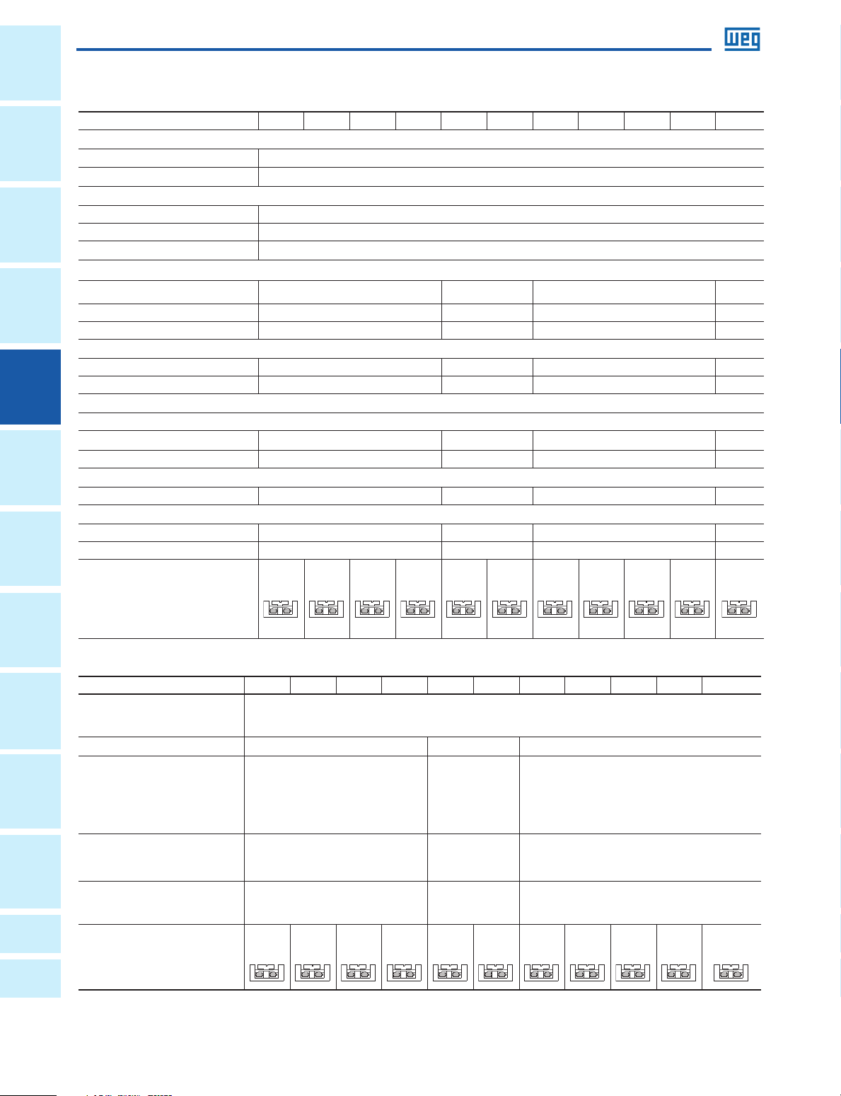
Control circuit ratings - AC Coil
TYPE CWM9 CWM12 CWM18 CWM25 CWM32 CWM40 CWM50 CWM65 CWM80 CWM95 CWM105
Rated Insulation Voltage Ui
Acc. IEC; VDE 0660 [V] 1000
Acc. UL; CSA [V] 600
Rated Operating Voltage Ue
Acc. IEC; VDE 0660 [V] 690
Acc. UL; CSA [V] 600
Standard Voltages 60Hz
Coil Operating limits
Monofrequency coils xUc [V] 0.85...1.1 -
Pick-up xUc [V] 0.4...0.76 0.5...0.76 0.5...0.76 -
Drop-out xUc [V] 0.25...0.65 0.3...0.65 0.25...0.6 -
Operating Time
Coil energization - N.O. [ms] 8...20 10...19 15...30 -
Coil de-energization - N.O. [ms] 6...13 5...25 9...15 -
Coil Consumption
Single coils
Sealed [VA] 4...7.2 6.6...12.5 13.1....19.1 -
Inrush [VA] 70 98 255 -
Thermal Power Dissipation
60Hz [W] 2.6 4.3 8.0 -
Power Factor
Closed Cos phi 0.28 0.34 0.32 -
Opened Cos phi 0.85 0.69 0.54 -
Stranded / Solid
[AWG]
(UL / CSA)
[V] 24...600
2x12-10 2x12-10 2x12-10 2x12-10 2x12-10 2x12-10 2x12-10 2x12-10 2x12-10 2x12-10 2x12-10
and Pilot
Lights
Blocks
Correction
Factor
A
B
Control circuit ratings - DC Coil
TYPE CWM9 CWM12 CWM18 CWM25 CWM32 CWM40 CWM50 CWM65 CWM80 CWM95 CWM105
Rated Insulation Voltage Ui
Acc. IEC; VDE 0660
Acc. UL; CSA
Standard Voltages
Terminal
Coil Operating limits
Pick-up xUc
Drop-out xUc
Operating Time
Coil energization - N.O. [ms]
Coil de-energization - N.O. [ms]
Coil Consumption
Sealed [W]
Appendix
Inrush [W]
Appendix
Stranded / Solid
(UL / CSA)
166
[V]
[V]
[V] 12...440 24...240 24...240
[AWG]
[V]
[V]
2x12-10 2x12-10 2x12-10 2x12-10 2x12-10 2x12-10 2x12-10 2x12-10 2x12-10 2x12-10 2x12-10
0.4...0.7
0.15...0.4
35...45
7...12
3.8...9.0
3.8...9.0
0.85...1.1
1000
600
0.45...0.75
0.15...0.45
40...55
30...65
6
240
0.7...0.8
0.4...0.6
50...60
55...60
6.5
340
Data is subject to change without notice.
Page 2
Contactors
CWM Series - IEC Standard Contactors
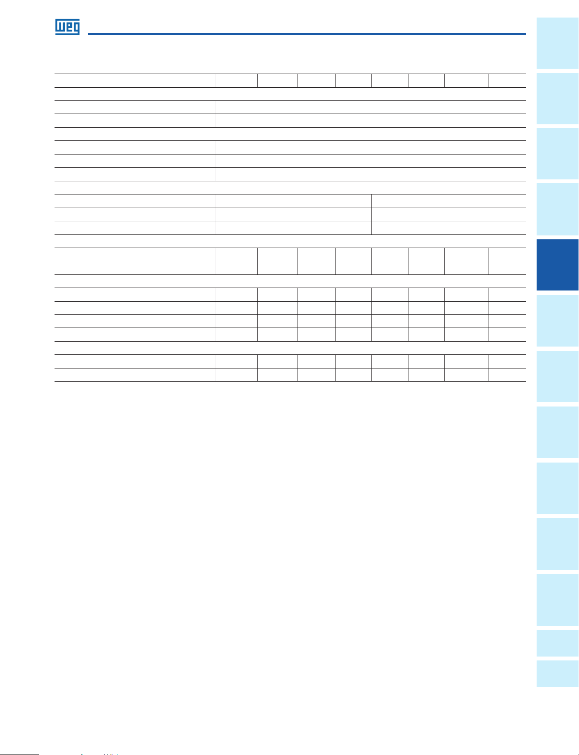
IEC Contactors - CWM Series
TYPE CWM112 CWM150 CWM180 CWM250 CWM300 CWM400 CWM630 CWM800
Rated Insulation Voltage Ui
Acc. IEC; VDE 0660 [V] 1000
Acc. UL; CSA [V] 600
Rated Operating Voltage Ue
Acc. IEC; VDE 0660 [V] 690
Acc. UL; CSA [V] 600
Standard Voltages 50Hz; 60Hz; DC [V] 24…600
Coil Operating limits
xUc [V] 0.65…1.1 0.85...1.1
Pick-up xUc [V] 0.70...0.85 0.77...0.83
Drop-out xUc [V] 0.40...0.60 0.48...0.53
Operating Time
Coil energization - N.O. [ms] 60…70 60…70 60…70 60…70 60…70 64…68 66…70 66…70
Coil de-energization - N.O. [ms] 13…17 13…17 13…17 13…17 13…17 43…47 45…49 45…49
Coil Consumption
Sealed AC [VA] 14.8 14.8 14.1 14.1 14.1 14 17 29
Inrush AC [VA] 213 213 214 229 229 571 1000 1000
Sealed DC [VA] 2.4 2.4 2.4 2.5 2.5 14 17 29
Inrush DC [VA] 166 166 154 171 171 571 1000 1000
Thermal Power Dissipation
AC [W] 3.9 3.9 3.8 3.7 3.7 4.7 4.9 5.3
DC [W] 2.4 2.4 2.4 2.5 2.5 5.0 6.3 7.8
General
Information
Protection
Switches
Disconnect
Protectors
Overloads Contactors Motor
Starters
Enclosed
Relays Circuit
Lights
and Pilot
Pushbuttons
Blocks
Terminal
Power
Factor
Correction
A
Appendix
B
Appendix
Data is subject to change without notice.
WEG Automation - Products and Solutions | 167
Page 3
Information
General
Contactors
CWM Series - IEC Standard Contactors
Protection
Circuit
Disconnect
Switches
Protectors
Motor
Contactors Power
Overloads Relays Pushbuttons
Enclosed
Starters
and Pilot
Lights
Terminal
Blocks
Correction
Factor
Appendix
A
Appendix
B
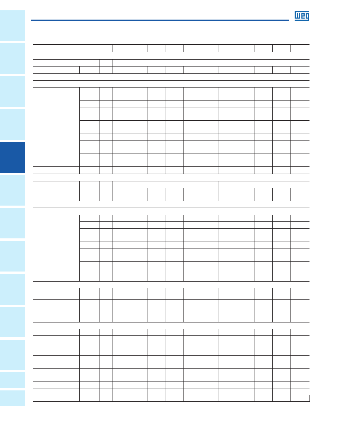
Power Contacts
TYPE CWM9 CWM12 CWM18 CWM25 CWM32 CWM40 CWM50 CWM65 CWM80 CWM95 CWM105
Standard UL/CSA Ratings
Rated Operating Voltage
AC-1 (General Purpose)
Switching Motor Loads
Full Voltage - 50/60Hz
1-phase
3-phase
Short Circuit Rating
115V [A] 9.8 13.8 16 24 34 34 56 56 80 80 100
230V [A] 10 12 17 28 28 28 40 50 68 68 88
115V [HP] 1/2 3/4 1 2 3 3 5 5 7-1/2 7-1/2 10
230V [HP] 1-1/2 2 3 5 5 7 1/2 10 10 15 15 20
200V [A] 11 11 17.5 25 32.2 32.2 48.3 62.1 62.1 78.2 92
230V [A] 9.6 9.6 15.2 22 28 42 42 54 68 80 104
460V [A] 7.6 11 14 21 27 40 52 65 65 77 96
575V [A] 9 11 17 17 27 27 41 52
200V [HP] 3 3 5 7-1/2 10 10 15 20 20 25 30
230V [HP] 3 3 5 7-1/2 10 15 15 20 25 30 40
460V [HP] 5 7-1/2 10 15 20 30 40 50 50 60 75
575V [HP] 7-1/2 10 15 15 25 25 40 50 60 75 75
600V [kA] 5 5 5 5 5 5 10 10 10 10 10
[V] 600
[A] 25 25 32 32 60 60 90 110 110 140 140
62 77 77
Standard IEC Ratings (IEC EN 60947)
Rated Operating Voltage
Rated Thermal Current
Ith
Switching Motor Loads
AC-3 - 50/60Hz
220-240V [A] 9 12 18 25 32 40 50 65 80 95 105
380-400V [A] 9 12 18 25 32 40 50 65 80 95 105
415-440V [A] 9 12 18 25 32 40 50 65 80 95 105
500V [A] 7.5 10.5
3-phase
Maximum Switching Rate
AC-4
200,000 operations; <= 690V [A]
50/60Hz 220-230V [kW] 1.1 1.5 1.5 3 4 4.5 5.5 7.5 9.2 11 12.5
660-690V [A] 7 9 13 15 22 25 34 44 48 60 80
220-240V [kW] 2.2 3 4 7.5 9 11 15 18.5 22 25 30
380-400V [kW] 4 5.5 7.5 11 15 18.5 22 30 37 45 55
415-440V [kW] 4 5.5 7.5 11 15 22 25 37 45 50 55
500V [kW] 5.5 7.5 10 15 18.5 25 30 40 45 55 65
660-690V [kW] 5.5 7.5 10 15 18.5 30 35 45 45 55 65
AC-1
AC-3
no load
380-400V [kW] 2.2 3 3.7 5.5 7.5 9.2 11 15 18.5 22 22
415-440V [kW] 2.2 3.7 4.5 5.5 9.2 11 11 15 22 22 30
500V [kW] 3 4 5.5 7.5 10 11 15 18.5 22 25 30
660-690V [kW] 3 4.5 5.5 7.5 11 12.5 15 20 25 30 33
[V] 690 1000
[A] 25 25 32 45 60 60 90 110 110 140 140
14 19 24 32 38 55 63 79 85
[ops/
1,200 1,200 1,200 1,200 1,200 1,200 1,200 1,200 1,200 1,200 1,200
hr]
[ops/
1,200 1,200 1,200 1,200 1,200 1,200 1,200 1,200 1,200 600 600
hr]
[ops/
9,000 9,000 9,000 9,000 9,000 9,000 5,000 5,000 5,000 5,000 5,000
hr]
5 7 8 12 16 18.5 23 30 37 44 50
[HP] 1.5 2 2 4 5.4 6 7.5 10 12.5 15 17
[HP] 3 4 5 7.5 10 12.5 15 20 25 30 30
[HP] 3 5 6 7.5 12.5 15 15 20 30 30 40
[HP] 4 5.4 7.5 10 13 15 20 25 30 33 40
[HP] 4 6 7.5 10 15 17 20 27
33 40 45
Power Contacts continued
168
Data is subject to change without notice.
Page 4

Contactors
CWM Series - IEC Standard Contactors
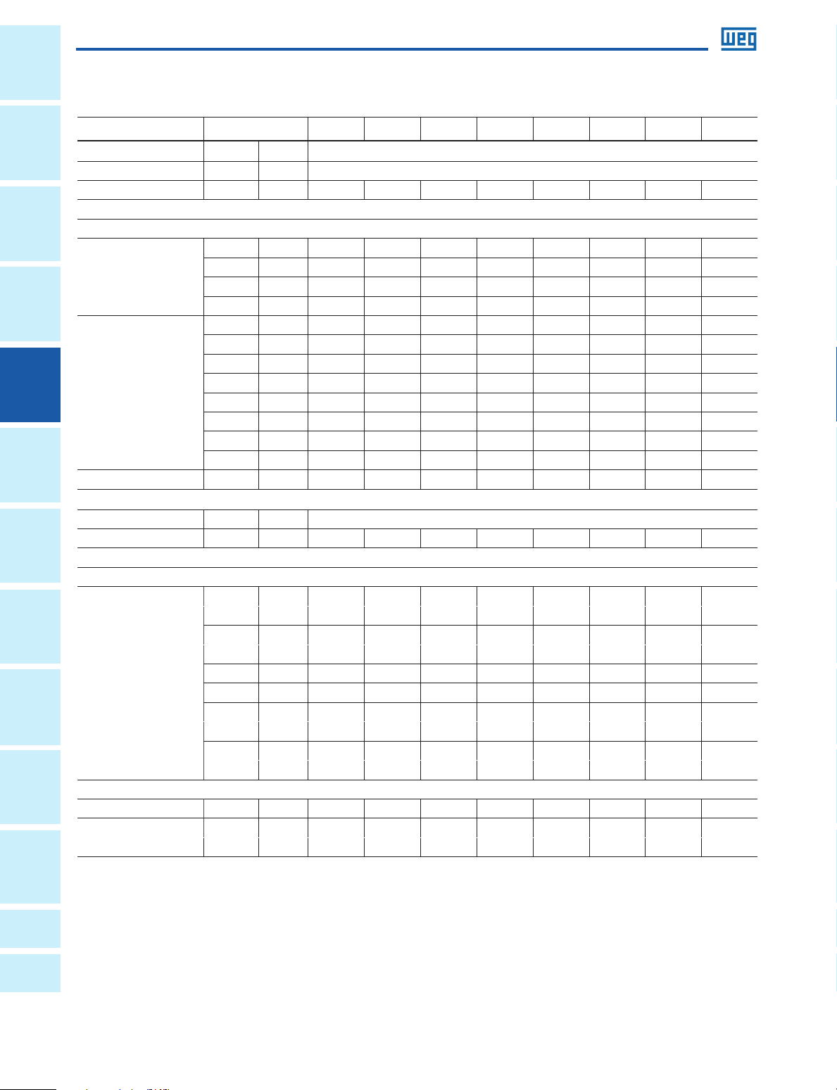
Power Contacts cont.
Type CWM9 CWM12 CWM18 CWM25 CWM32 CWM40 CWM50 CWM65 CWM80 CWM95 CWM105
Breaking Capacity Ue=400V [A] 250 250 250 450 450 920 920 920 920 1050 1050
Ue=500V [A] 250 250 250 320 450 920 920 920 920 1050 1050
Ue=690V [A] 130 130 130 170 205 780 780 780 780 950 950
Impedance per Pole [mW] 2.41 2.41 2.35 1.65 1.28 0.95 0.85 0.86 0.86 0.76 0.76
Power Dissipation per Pole
AC-1 [W] 1.47 1.47 2.46 3.34 4.6 3.42 6.86 10.40 10.40 14.89 14.89
AC-3 [W] 0.19 0.34 0.78 1.03 1.31 1.52 2.12 3.63 5.5 6.86 8.37
Short Time Current Icw
1 sec. [A] 455 455 570 630 1010 1265 1580 2530 2530 3300 3300
5 sec. [A] 205 205 254 280 450 450 710 1130 1130 1485 1485
10 sec. [A] 144 144 180 200 320 400 500 800 800 1050 1050
30 sec. [A]
1 min. [A] 60 60 74 80 130 165 205 325 325 430 430
3 min. [A] 35 35 46 50 90 100 120 185 185 250 250
Rec. time [min.] 10 10 10 10 10 10 10 10 10 10 10
Short Circuit Coordination
Acc. to IEC
Coordination Type “1” gL/gG [A] 50 50 63 63 100 125 200 200 200 250 250
Coordination Type “2” gL/gG [A] 25 35 35 50 63 80 100 125 125 160 200
Acc. to UL/CSA J Type [A] 25 35 40 45 60 70 100 125 125 150 200
85 85 104 115 185 230 290 460 460 600 600
General
Information
Protection
Switches
Disconnect
Protectors
Built-in Auxiliary Contacts
TYPE CWM9 CWM12 CWM18
Rated Insulation Voltage Ui
Acc. IEC; VDE 0660 [V] 1000
Acc. UL; CSA [V] 600
Rated Operating Voltage Ue
Acc. IEC; VDE 0660 [V] 690
Acc. UL; CSA [V] 600
Rated Thermal Current Ith <=55
Rated Operating Current Ie
Acc. IEC 60947-5-1 / AC-15
Acc. UL; CSA A600
Rated Operating Current Ie
Acc. IEC 60947-5-1 / DC-13
Acc. UL; CSA P600
Making Capacity Im
AC-15 / AC-11 Ue <= 690V 50/60Hz [A] 250
DC-13 / DC-11 Ue <= 440Vdc [A] 250
Breaking Capacity Ic
AC-15 / AC-11 Ue <= 400V 50/60Hz [A] 250
DC-13 / DC-11 Ue <=220Vdc [A] 2
Short Circuit Protection with Fuses
Acc. IEC 60947-5-1 - gL/gG [A] 10
Minimum Switching Capacity [V/mA] 17/5
Electrical Endurance Million ops. 1
Mechanical Endurance Million ops. 10
Guaranteed Non-Overlap Time [ms] 1.5
Insulation Resistance [MOhm] >10
o
C [A] 20
110-127V [A] 10
220-240V [A] 10
380-400V [A] 6
415-450V [A] 5
500V [A] 4
660-690V [A] 2
24V [A] 6
48V [A] 4
110V [A] 2
220V [A] 0.7
440V [A] 0.7
Overloads Contactors Motor
Starters
Enclosed
Relays Circuit
Lights
and Pilot
Pushbuttons
Blocks
Terminal
Power
Factor
Correction
A
Appendix
B
Appendix
Data is subject to change without notice.
WEG Automation - Products and Solutions | 169
Page 5
Information
General
Contactors
CWM Series - IEC Standard Contactors
Protection
Circuit
Disconnect
Switches
Protectors
Motor
Contactors Power
Overloads Relays Pushbuttons
Enclosed
Starters
and Pilot
Lights
Terminal
Blocks
Correction
Factor
Power Contacts cont.
TYPE Units CWM112 CWM150 CWM180 CWM250 CWM300 CWM400 CWM630 CWM800
NEMA Ratings
Rated Operating Voltage [V] 600
AC-1 (General Purpose) [A] 170 170 200 300 400 450 660 900
Switching Motor Loads
Full Voltage - 50/60Hz
115V [A] - - - - - - - -
1-phase
3-phase
Short Circuit Rating 600V [kA] 10 10 10 18 18 18 30 30
230V [A] - - - - - - - -
115V [HP] - - - - - - - -
230V [HP] - - - - - - - -
200V [A] 120 150 177 221 285 359 414 552
230V [A] 130 154 192 248 312 360 480 772
460V [A] 124 156 180 240 302 361 477 -
575V [A] 99 144 192 242 336 289 382 -
200V [HP] 40 50 60 75 100 125 150 200
230V [HP] 50 60 75 100 125 150 200 300
460V [HP] 100 125 150 200
575V [HP] 100 150 200 250 350 300 400 600
250 300 400 600
Standard IEC Ratings (IEC/EN 60947)
Rated Operating Voltage [V] 1000
Rated Thermal Current Ith [A] 180 225 225 350 350 450 660 900
Switching Motor Loads
AC-3 - 50/60Hz
220-240V [A] 112 150 180 250 300 400 630 800
380-400V [A] 112 150 180 250 300 400 630 800
415-440V [A] 112 150 180 250 300 400 630 800
500V [A] 95 130 155 220 265 350 500 720
3-phase
Maximum Switching Rate
660-690V [A] 82 110 135 185 220 300 420 630
220-240V [kW] 30 45 55 75 90 110 185 220
380-400V [kW] 55 75 90 132 160 220 330 450
415-440V [kW] 55 90 110 150 185 220 370 500
500V [kW] 55 90 110 160 200 220 330 500
660-690V [kW]
AC-1 [ops/hr] 600 600 600 600 600 500 500 500
AC-3 [ops/hr] 600 600 600 600 600 500 500 500
no load [ops/hr] 1,000 1,000 1,000 1,000 1,000 1,000 1,000 1,000
75 110 110 160 200 260 400 560
Appendix
A
Appendix
B
170
Data is subject to change without notice.
Page 6

Contactors
CWM Series - IEC Standard Contactors
Power Contact cont.
TYPE CWM112 CWM150 CWM180 CWM250 CWM300 CWM400 CWM500 CWM630 CWM800
AC-4 Voltage Units
200,000 operations; <= 690V [A] 50 55 58 100 130 - - - -
220-230V [kW] 18.5 20 22 37 45 90 - 110 185
[HP] 25 27 30 50 60 125 - 150 250
380-400V [kW] 30 33 37 55 75 150 - 220 330
[HP] 40 44 50 75 100 200 - 300 450
50/60Hz
Maximum Switching
Rate
Making Capacity [A] 1430 1820 2100 2600 3000 - - - -
Breaking Capacity
Impedance per pole [mW] 0.5 0.5 0.45 0.3 0.3 - - - -
Power Dissipation per Pole
Short Time Current Icw
0°≤ 104°F
Short Circuit Coordination
Acc. to IEC
Coordination type “1” gL/gG [A] 315 355 355 500 630 630 - 800 1000
Coordination type “2” gL/gG [A] 224 250 250 400 500 - - - -
Acc. to UL/CSA
415-440V [kW] 37 40 45 63 80 185 - 220 370
[HP] 50 54 60 84 107 250 - 300 500
500V [kW] 40 45 50 75 90 - - - -
[HP] 54 60 67 100 121 - - - -
660-690V [kW] 45 50 55 90 100 - - - -
[HP] 600 67 75 121 133 - - - -
[ops/hr] 150 150 150 150 150 - - - -
Ue<=400V [A] 1290 1350 1400 2000 - 4000 - 6300 8000
Ue=500V [A] 1290 1350 1400 2000 - 4000 6300 8000
AC-1 [W] 16 25 21.6 35 45.7 - - - -
AC-3 [W] 6.2 11.1 13.8 17.9 25.7 - - - -
1 sec. [A] 3165 3763 4649 4427 - - - - -
5 sec. [A] 1820 2164 2673 2546 - - - - -
10 sec. [A] 1430 1700 2100 2000 - - - - -
30 sec. [A] 826 980 1212 1155 - - - - -
1 min. [A] 584 694 857 816 - - - - -
3 min. [A] 337 401 495 471 - - - - -
Recovery
time
J Type [A] 250 350 400 500 700 700 - 900 1100
[min.] 10 10 10 10 10 - - - -
General
Information
Protection
Switches
Disconnect
Protectors
Overloads Contactors Motor
Starters
Enclosed
Relays Circuit
Lights
and Pilot
Pushbuttons
Blocks
Terminal
Data is subject to change without notice.
WEG Automation - Products and Solutions | 171
Power
Factor
A
Appendix
B
Appendix
Correction
Page 7

Information
General
Contactors
CWM Series - IEC Standard Contactors
General Ratings
Protection
Circuit
Standards Units
Rated Insulation Voltage Ui
Acc. IEC; VDE 0660 [V] 1000
Acc. UL; CSA [V] 600
Disconnect
Switches
Protectors
Starters
Rated Impulse Voltage Uimp
Rated Operating Frequency [Hz] 25…400
Degree of Protection
Main terminals IP10
Coil terminals
Auxiliary terminals
Motor
Ambient Temperature
Storage -55 to +80oC (-67 to +176oF)
Operating -25 to +55oC (-13 to +131oF)
Altitude
Up to 1,500m Nominal values
Contactors Power
Pollution Degree 3
Climatic Withstand According to IEC 60680-2
Mounting 35mm rail Acc. DIN EN 50 022
Vibration Resistance (5 to 200 Hz)
Contactor open [g] 3 3 3 7.5 8 8 4.5 4.5 4.5 5 5
Overloads Relays Pushbuttons
Contactor closed at Uc [g] 6 6 6 8 12 12 9 9 9 7 7
Mechanical Endurance
AC Coil
Electrical Endurance AC-3
Shock Resistance (1/2 sin wave = 11ms)
Enclosed
Contactor open [g] 8 8 8 8 7 7 6 6 6 6 6
Contactor closed at Uc [g] 12 12 12 12 12 12 10 10 10 10 10
Weight [kg] 0.30 0.30 0.30 0.30 0.52 0.54
AC Coil [lb] 0.65 0.65 0.65 0.65 1.15 1.19 2.44 2.47 2.49 3.20 3.24
Terminal Capacity Cross/Slotted Combination Allen Head
TYPE CWM9 CWM12 CWM18 CWM25 CWM32 CWM40 CWM50 CWM65 CWM80 CWM95 CWM105
Devices according to International Standards IEC 60947-1 / 60947-4-1, European Standards EN 60947-1 / 60947-4-1, Underwriters Laboratories - UL 508;
CSA C.22.2/14; VDE 0660/102
6 8 Acc. IEC60947-1 [kV]
Protection against direct contact Acc. VDE 0160 - Part. 100
IP20
See graphic on page 174
Million
ops.
Million
ops.
1.8 1.6 1.2 1.2 1.2 1.2 1.1 1.1 1.1 1.1 1.1
10
1.11 1.12 1.13 1.45 1.47
and Pilot
Lights
Blocks
Correction
Factor
A
B
Fine - Stranded with sleeve
Coarse - Stranded / Solid
Stranded / Solid (UL / CSA)
Terminal
Drive Size Screwdriver - Philips #2 5/32” (4mm.)
Tightening Torque
Appendix
Appendix
Top
[mm2]
2x0.5-2.5 2x0.5-2.5 2x0.5-2.5 2x1-2.5 0.75-16 0.75-16 1-35 1-35 1-35 1.5-50 1.5-50
Bottom
or 2x2.5-6 or 2x2.5-6 or 2x2.5-6 or 2x2.5-10 1.0-16 1.0-16 2.5-35 2.5-35 2.5-35 4-35 4-35
[mm2]
Top
[mm2]
Bottom
[mm2]
Top
[AWG]
Bottom
[AWG]
lb-in
(Nm)
2x1-2.5 2x1-2.5 2x1-2.5 2x1-2.5 1-16 1-16 1.5-35 1.5-35 1.5-35 2.5-50 2.5-50
or 2x2.5-6 or 2x2.5-6 or 2x2.5-6 or 2x2.5-10 1.5-16 1.5-16 6-35 6-35 6-35 6-35 6-35
2x20-12 2x20-12 2x20-12 2x18-12 18-6 18-6 16-2 16-2 16-2 16-1 16-1
or 2x12-10 or 2x12-10 or 2x12-10 or 2x12-8 16-6 16-6 14-2 14-2 14-2 10-2 10-2
8.9...15
(1...1.7)
8.9...15
(1...1.7)
8.9...15
(1...1.7)
14.2...26.6
(1.6...3)
22.1...35..4
(2.5...4)
22.1...35..4
(2.5...4)
35.4...53.1
(4...6)
35.4...53.1
(4...6)
35.4...53.1
(4...6)
44.3...57.5
(5...6.5)
44.3...57.5
(5...6.5)
172
Data is subject to change without notice.
Page 8

Contactors
CWM Series - IEC Standard Contactors
General Ratings
TYPE CWM112 CWM150 CWM180 CWM250 CWM300 CWM400 CWM630 CWM800
Standards
Units
Rated Insulation Voltage Ui
Acc. IEC; VDE 0660 [V] 1000
Acc. UL; CSA [V] 600
Rated Impulse Voltage Uimp
Acc. IEC60947-1 [kV] 8
Rated Operating Frequency [Hz] 25…400
Degree of protection Protection against direct contact acc. VDE 0160 - Part. 100
Main terminals IP00
Coil terminals IP20
Auxiliary terminals IP20
Ambient Temperature
Storage -55 to +80
Operating -25 to +55
Altitude
Up to 1,500m Nominal values
Other altitudes
Pollution Degree 3
Climatic withstand According to IEC 68-2
Mounting Screw to panel
Vibration Resistance (5 to 200 Hz)
Contactor open [g] 4
Contactor closed at Uc [g] 4
Mechanical Endurance
AC Coil
Electrical Endurance AC-3
Million
Million
Shock Resistance (1/2 sin wave = 11ms)
Contactor open [g] 3
Contactor closed at Uc [g] 3
Weight
AC/DC Coil
Terminal Capacity
Fine - Stranded with
sleeve
[mm2] 2 x (25-70) 2 x (50-120) 2 x (50-150) 1 x 150 1 x 240 1 x 240
AWG wires with end sleeve 1 x 300 or 2 x 10⁷ 1 x 500 or 2 x 300 Nº2 30×5 Nº2 50×5 Nº2 60×5
Busbars [mm] 2 x (15 x 3) 2 x (20 x 3) 2 x (30 x 5) - -
Tightening Torque
Devices according to International Standards IEC 60947-1 / 60947-4-1, European Standards EN 60947-1 / 60947-4-1,
Underwriters Laboratories - UL 508; CSA C.22.2/14; VDE 0660/102
o
C (-67 to +176oF)
o
C (-13 to +131oF)
See graphic on page 174 up to 2000m
ops.
ops.
1.1 1.1 1.0 1.0 1.0 0.5
10 5
[kg] 2.54 2.54 4.04 6.14 6.14 9.2 22.4 22.4
[lb] 5.60 5.60 8.91 13.54 13.54 20 49 49
lb-in
(Nm)
47.8-53.1(5.4-6) 123.9-141.6 (14-16) 203.6-230.1 (23-26) 203.6 (23)
504.5
(57)
504.5 (57)
-
General
Information
Protection
Switches
Disconnect
Protectors
Overloads Contactors Motor
Starters
Enclosed
Relays Circuit
Lights
and Pilot
Pushbuttons
Blocks
Terminal
Data is subject to change without notice.
WEG Automation - Products and Solutions | 173
Power
Factor
A
Appendix
B
Appendix
Correction
Page 9

Information
General
Protection
Circuit
Disconnect
Switches
Protectors
Motor
Contactors Power
Overloads Relays Pushbuttons
Enclosed
Starters
and Pilot
Lights
Contactors
CWM Series - IEC Standard Contactors
Auxiliary contact block ratings
TYPE BCXMF BCXML BCXMRL BLIM.02
Rated Insulation Voltage Ui
Acc. IEC; VDE 0660 [V] 1000
Acc. UL; CSA [V] 600
Rated Operating Voltage Ue
Acc. IEC; VDE 0660 [V] 690
Acc. UL; CSA [V] 600
Rated Thermal Current Ith <=55
Rated Operating Current Ie
Acc. IEC 60947-5-1 / AC-15
Acc. UL; CSA A600
Rated Operating Current Ie
Acc. IEC 60947-5-1 / DC-13
Acc. UL; CSA Q600
Making Capacity Im
AC-15 / AC-11 Ue <= 400V 50/60Hz [A] 90
DC-13 / DC-11 Ue <= 220Vdc [A] 90
Breaking Capacity Ic
AC-15 / AC-11 Ue <= 400V 50/60Hz [A] 60
DC-13 / DC-11 Ue <= 220Vdc [A] 0.95
Short Circuit Protection with Fuses
Acc. IEC 60947-5-1 - gL/gG [A] 10
Minimum Switching Capacity [V/mA] 17/5
Electrical Endurance Million ops. 1
Mechanical Endurance Million ops. 10
Guaranteed Non-Overlap Time [ms] 1.5
Insulation Resistance [MOhm] >10
o
C [A] 10
110-127V [A] 6
220-240V [A] 6
380-400V [A] 4
415-450V [A] 3.5
500V [A] 2.5
660-690V [A] 1.5
24V [A] 4
48V [A] 2
110V [A] 0.7
220V [A] 0.3
440V [A] 0.15
Blocks
Correction
Factor
A
B
Graphic Altitude
Terminal
Appendix
Appendix
Meters
174
Derating Factor
NOTE:
Altitude compensation in CWM Series contactors, considers a factor according to which the rated power must be reduced.
The derating of the permissible operating power for installation altitudes
above 1,500 m (5,000 ft) is calculated according to:
Total derating = Derating
current
x Derating
voltage
Example: Altitude: 3,000 m (10,000 ft):
Derating current K1 = 0.85
Derating voltage K2 = 0.88
Total derating = 0.85 x 0.88 = 0.75 x HP
Data is subject to change without notice.
 Loading...