

Page 1

Motors | Automation | Energy | Transmission & Distribution | Coatings
Frequency Inverter
CFW701 V2.0X
Programming Manual
Page 2

Page 3

Programming Manual
Series: CFW701
Language: English
Document Number: 10001461481 / 01
Software Version: 2.0X
Publication Date: 04/2014
Page 4

Page 5

Summary
QUICK PARAMETER REFERENCE, FAULTS AND ALARMS .................0 -1
1 SAFETY NOTICES ................................................................................. 1-1
1.1 SAFETY NOTICES IN THIS MANUAL ............................................................................................1-1
1.2 SAFETY NOTICES ON THE PRODUCT ......................................................................................... 1-1
1.3 PRELIMINARY RECOMMENDATIONS ..........................................................................................1-2
2 GENERAL INFORMATION ......................................................................2-1
2.1 ABOUT THIS MANUAL ...................................................................................................................2-1
2.2 TERMINOLOGY AND DEFINITIONS..............................................................................................2-1
2.2.1 Terms and Definitions Used in the Manual ......................................................................2-1
2.2.2 Numerical Representation ................................................................................................ 2-3
2.2.3 Symbols for the Parameter Properties Description ...................................................... 2-3
3 ABOUT THE CFW701 .............................................................................3 -1
4 KEYPAD (HMI) .........................................................................................4 -1
5 PROGRAMMING BASIC INSTRUCTIONS .............................................5 -1
5.1 PARAMETERS STRUCTURE ......................................................................................................... 5-1
5.2 GROUPS ACCESSED IN THE OPTION MENU IN THE MONITORING MODE .......................... 5 -1
5.3 PASSWORD SETTING IN P0000 ................................................................................................... 5-1
5.4 HMI .................................................................................................................................................. 5-2
5.5 INDIRECT ENGINEERING UNITS ................................................................................................. 5-6
5.6 DISPLAY INDICATIONS IN THE MONITORING MODE SETTINGS ..........................................5 -14
5.7 INCOMPATIBILITY BETWEEN PARAMETERS ..........................................................................5 -14
6 INVERTER MODEL AND ACCESSORIES IDENTIFICATION ...............6-1
6.1 INVERTER DATA ........................................................................................................................... 6 -1
7 STARTING-UP AND SETTINGS ............................................................. 7-1
7.1 BACKUP PARAMETERS ................................................................................................................. 7-1
8 AVAILABLE CONTROL TYPES ..............................................................8 -1
9 SCALAR CONTROL (V/f) ........................................................................ 9-1
9.1 V/f CONTROL .................................................................................................................................. 9-2
9.2 ADJUSTABLE V/f CURVE .............................................................................................................. 9-5
9.3 V/f CURRENT LIMITATION ........................................................................................................... 9-6
9.4 V/f DC VOLTAGE LIMITATION ....................................................................................................... 9-8
9.5 START-UP IN THE V/f CONTROL MODE ....................................................................................9 -11
10 V VW CONTROL .................................................................................10-1
10 .1 V VW CONTROL ........................................................................................................................ 10-3
10.2 MOTOR DATA ............................................................................................................................ 10-3
10. 3 V VW CONTROL MODE START-UP ........................................................................................ 10-4
11 VECTOR CONTROL ............................................................................ 11-1
11.1 SENSORLESS CONTROL .......................................................................................................... 11-1
11.2 I/f MODE (SENSORLESS) ..........................................................................................................11- 3
11.3 SELF-TUNING .............................................................................................................................11- 3
Page 6

Summary
11.4 OPTIMAL FLUX FOR SENSORLESS VECTOR CONTROL ....................................................11- 4
11.5 TORQUE CONTROL ....................................................................................................................11- 4
11.6 OPTIMAL BRAKING ...................................................................................................................11- 6
11.7 MOTOR DATA ..............................................................................................................................11-7
11.7.1 Adjustment of the Parameters P0409 to P0412 Based on the Motor Data Sheet .. 11-11
11.8 VECTOR CONTROL ................................................................................................................. 11-12
11.8.1 Speed Regulator ...........................................................................................................11-12
11.8.2 Current Regulator ......................................................................................................... 11-14
11.8.3 Flux Regulator ............................................................................................................... 11-14
11.8.4 I/f Control ...................................................................................................................... 11-16
11.8.5 Self-Tuning ...................................................................................................................... 11-17
11.8.6 Torque Current Limitation ............................................................................................11-2 0
11.8.7 Supervision of Motor Real Speed ................................................................................ 11-2 1
11.8.8 DC Link Regulator .........................................................................................................11-22
11.9 START-UP IN THE VECTOR MODES SENSORLESS .............................................................11- 2 4
12 FUNCTIONS COMMON TO ALL THE CONTROL MODES ............... 12-1
12 .1 R A MPS ......................................................................................................................................... 12-1
12.2 SPEED REFERENCES .............................................................................................................. 12-3
12.3 SPEED LIMITS ........................................................................................................................... 12-5
12.4 ZERO SPEED LOGIC ................................................................................................................. 12-6
12.5 FLYING START / RIDE-THROUGH ............................................................................................ 12- 8
12.5.1 V/f or VV W Flying Start .................................................................................................. 12-8
12.5.2 Vector Flying Start.......................................................................................................... 12-9
12.5.2.1 P0202 = 4 ........................................................................................................... 12-9
12 . 5 .3 V V W or V/f Ride-Through ........................................................................................... 12-11
12.5.4 Vector Ride-Through ..................................................................................................... 12-13
12.6 DC BRAKING ............................................................................................................................. 12-15
12.7 SKIP SPEED .............................................................................................................................12-18
13 DIGITAL AND ANALOG INPUTS AND OUTPUTS .............................13 -1
13.1 I/O CONFIGURATION .................................................................................................................13 -1
13.1.1 Analog Inputs ...................................................................................................................13 -1
13.1.2 Analog Outputs ............................................................................................................... 13- 6
13.1.3 Digital Inputs ................................................................................................................... 13-9
13.1.4 Digital Outputs / Relays ................................................................................................13 -14
13.1.5 Frequency Input ............................................................................................................ 13 -23
13.2 LOCAL AND REMOTE COMMAND ........................................................................................ 13-24
14 DYNAMIC BRAKING ........................................................................... 14-1
15 FAULTS AND ALARMS ....................................................................... 15 -1
15.1 MOTOR OVERLOAD PROTECTION ...........................................................................................15 -1
15.2 MOTOR OVERTEMPERATURE PROTECTION ........................................................................ 15-2
15.3 PROTECTIONS ........................................................................................................................... 15-4
16 READ ONLY PARAMETERS ............................................................... 16 -1
16.1 FAULT HISTORY ......................................................................................................................... 16 -7
17 COMMUNICATION ............................................................................. 17-1
17.1 RS-485 SERIAL INTERFACE ...................................................................................................... 17-1
17.2 COMMUNICATION BACNET ...................................................................................................... 17-1
17.3 COMMUNICATION METASYS N2 .............................................................................................. 17-1
17.4 COMMUNICATION STATES AND COMMANDS .......................................................................17-2
Page 7

Summary
18 SOFTPLC [50] ...................................................................................... 18 -1
19 HVAC FUNCTIONS ..............................................................................19-1
19.1 FIRE MODE ..................................................................................................................................19 -1
19.2 BYPASS MODE .......................................................................................................................... 19-4
19.3 ENERGY SAVING MODE ............................................................................................................19 -7
19.4 SHORT CYCLE PROTECTION ................................................................................................... 19-9
19.5 DRY PUMP .................................................................................................................................. 19-9
19.6 BROKEN BELT ..........................................................................................................................19 -11
19.7 FILTER MAINTENANCE ALARM ..............................................................................................19 -12
19.8 MAIN PID CONTROLLER .........................................................................................................19 -13
19.8.1 Sleep Mode .................................................................................................................... 19-21
19.9 EXTERNAL PID CONTROLLER 1 ........................................................................................... 19 -24
19.10 EXTERNAL PID CONTROLLER 2 .......................................................................................... 19 -31
19.11 HVAC FUNCTIONS LOGICAL STATUS ................................................................................. 19-38
19.12 VERSION OF THE HVAC APPLICATION ............................................................................... 19-39
Page 8

Summary
Page 9
Quick Parameter Reference, Faults and Alarms
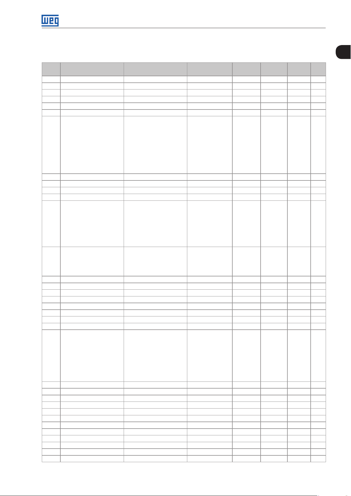
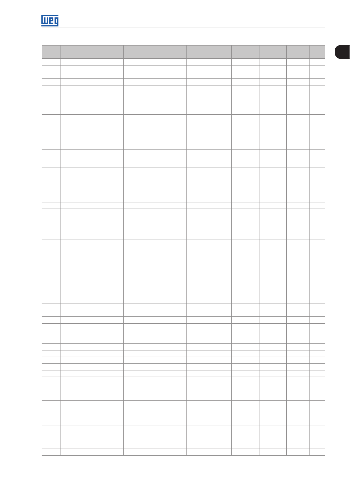
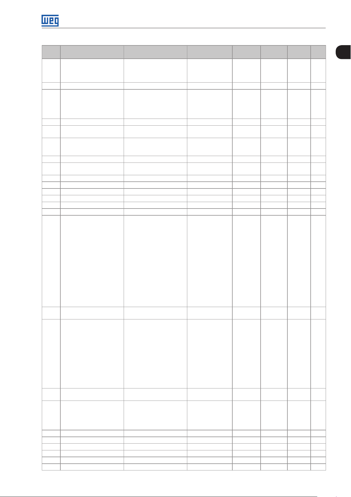
QUICK PARAMETER REFERENCE, FAULTS AND ALARMS
Param. Function
P0000 Access to Parameters 0 to 9999 0 5-1
P0001 Speed Reference 0 to 18000 rpm ro READ 16 -1
P0002 Motor Speed 0 to 18000 rpm ro READ 16 -1
P0003 Motor Current 0.0 to 4500.0 A ro READ 16-1
P0004 DC Link Voltage (Ud) 0 to 2000 V ro READ 16-2
P0005 Motor Frequency 0.0 to 1020.0 Hz ro READ 16-2
P0006 VFD Status 0 = Ready
P0007 Motor Voltage 0 to 2000 V ro READ 16-3
P0009 Motor Torque -1000.0 to 1000.0 % ro READ 16-3
P0 010 Output Power 0.0 to 6553.5 kW ro READ 16-4
P0 0 11 Output Cos φ 0.00 to 1.00 ro READ, I/O 16-4
P0 012 DI8 to DI1 Status Bit 0 = DI1
P0 013 DO5 to DO1 Status Bit 0 = DO1
P0 014 AO1 Value 0.00 to 100.00 % ro READ, I/O 13-6
P0 015 AO2 Value 0.00 to 100.00 % ro READ, I/O 13-6
P0 018 AI1 Value -100.00 to 100.00 % ro READ, I/O 13-1
P0 019 AI2 Value -100.00 to 100.00 % ro READ, I/O 13-1
P0020 AI3 Value -100.00 to 100.00 % ro READ, I/O 13-1
P0022 Frequency Input 3.0 to 6500.0 Hz ro READ, I/O 13-23
P0023 Software Version 0.00 to 655.35 ro READ 6-1
P0028 Accessories Config. 0000h to FFFFh ro READ 6-2
P0029 Power Hardware Config Bit 0 to 5 = Rated Current
P0030 IGBTs Temperature -20.0 to 150.0 °C ro READ 15-4
P0034 Internal Air Temp. -20.0 to 150.0 °C ro READ 15- 4
P0036 Fan Heatsink Speed 0 to 15000 rpm ro READ 16-5
P0037 Motor Overload Status 0 to 100 % ro READ 16-5
P0042 Powered Time 0 to 65535 h ro READ 16-6
P0043 Enabled Time 0.0 to 6553.5 h ro READ 16-6
P0044 kWh Output Energy 0 to 65535 kWh ro READ 16-6
P0045 Enabled Fan Time 0 to 65535 h ro READ 16-7
P0048 Present Alarm 0 to 999 ro READ 16 -7
P0049 Present Fault 0 to 999 ro READ 16-7
P0050 Last Fault 0 to 999 ro READ 16-8
P0054 Second Fault 0 to 999 ro READ 16-8
Adjustable
Range
1 = Run
2 = Undervoltage
3 = Fault
4 = Self-Tuning
5 = Configuration
6 = DC-Braking
7 = STO
8 = Fire Mode
9 = Bypass
Bit 1 = DI2
Bit 2 = DI3
Bit 3 = DI4
Bit 4 = DI5
Bit 5 = DI6
Bit 6 = DI7
Bit 7 = DI8
Bit 1 = DO2
Bit 2 = DO3
Bit 3 = DO4
Bit 4 = DO5
Bit 6 and 7 = Rated Voltage
Bit 8 = RFI Filter
Bit 9 = Safety Relay
Bit 10 = (0)24 V/(1)DC Link
Bit 11 = Always 0
Bit 12 = Dyn. Brak. IGBT
Bit 13 = Special
Bit 14 and 15 = Reserved
Factory
Setting
User
Setting
Propr. Groups Pág.
ro READ 16-2
ro READ, I/O 13-9
ro READ, I/O 13-14
ro READ 6-2
0
CFW701 | 0-1
Page 10
Quick Parameter Reference, Faults and Alarms
0
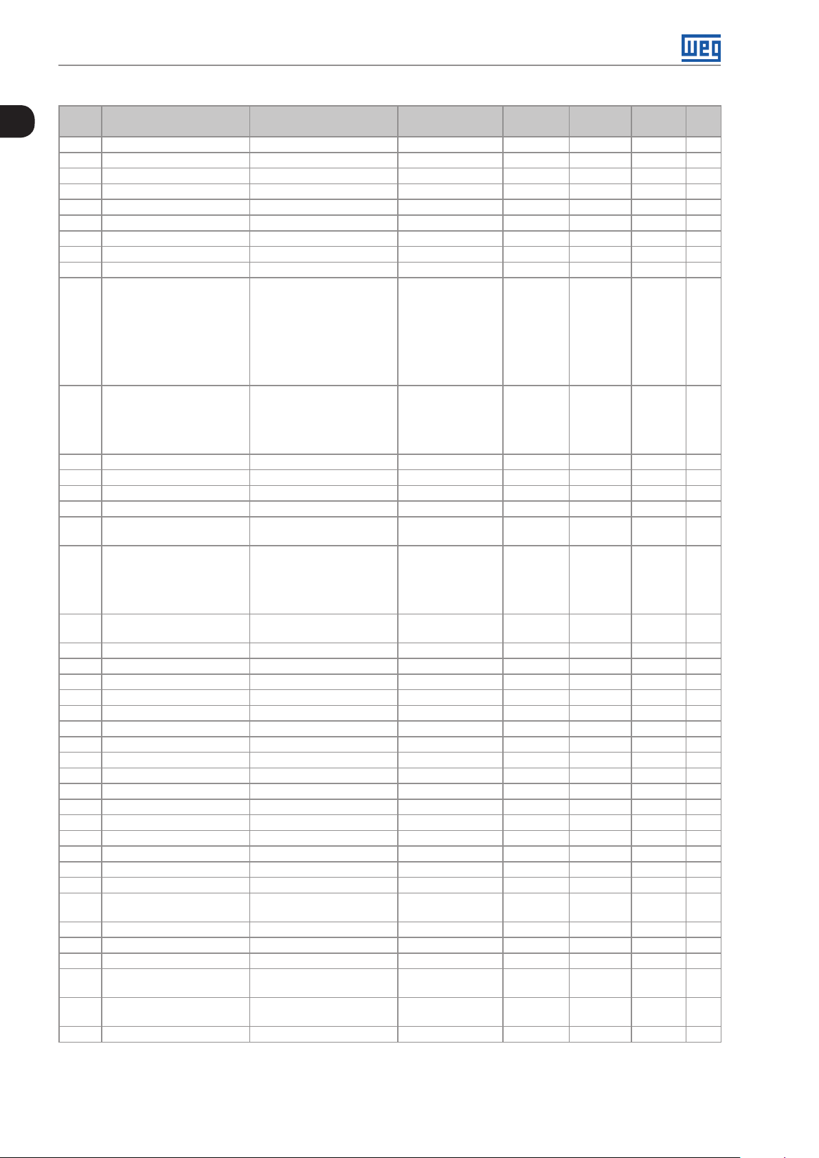
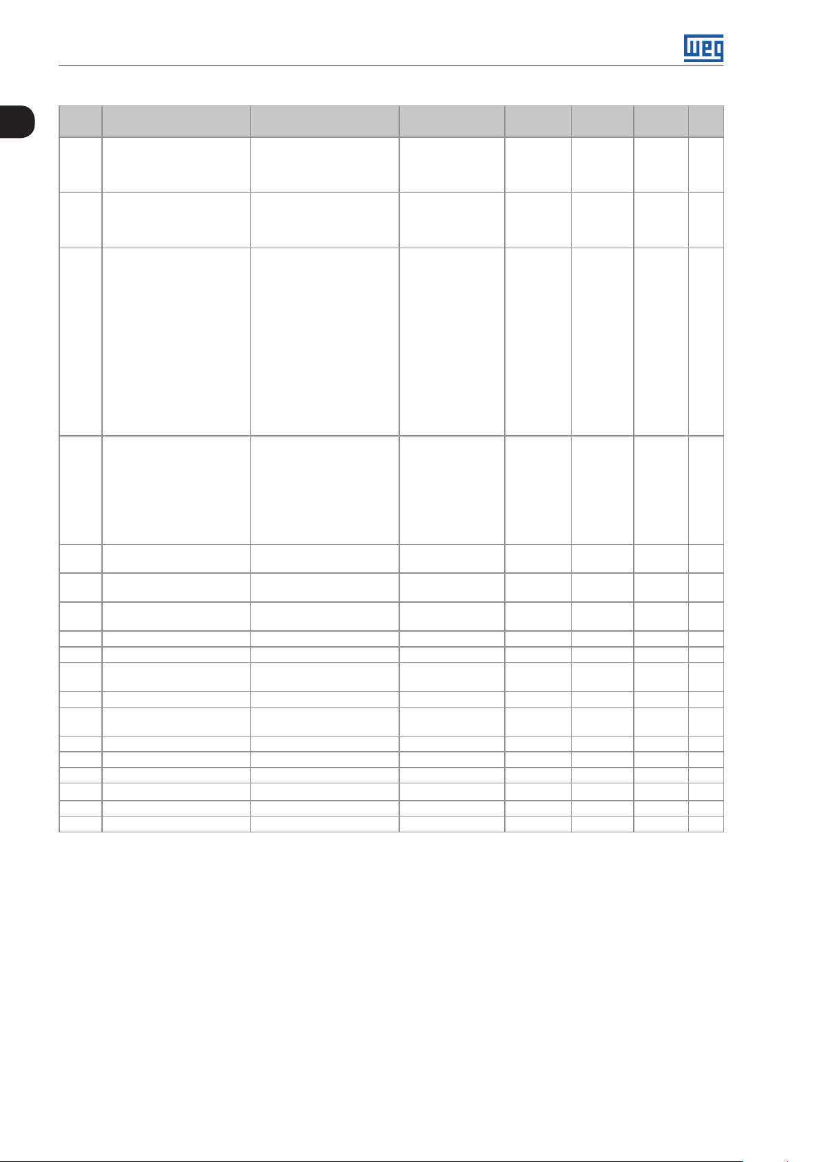
Param. Function
Adjustable
Range
Factory
Setting
User
Setting
Propr. Groups Pág.
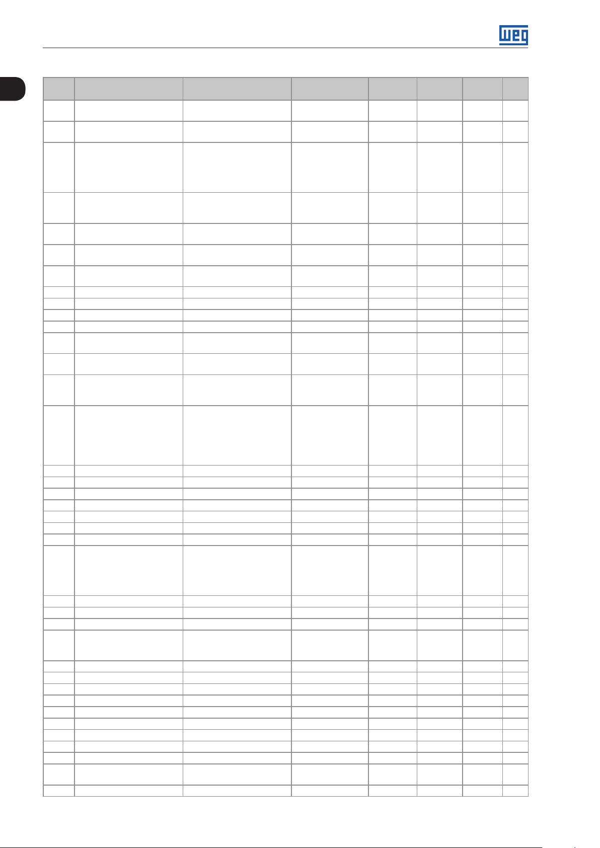
P0058 Third Fault 0 to 999 ro READ 16- 8
P0062 Fourth Fault 0 to 999 ro READ 16-8
P0066 Fifth Fault 0 to 999 ro READ 16- 8
P0090 Current At Last Fault 0.0 to 4500.0 A ro READ 16 -8
P0091 DC Link At Last Fault 0 to 2000 V ro READ 16-8
P0092 Speed At Last Fault 0 to 18000 rpm ro READ 16-9
P0093 Reference Last Fault 0 to 18000 rpm ro READ 16 -9
P0094 Frequency Last Fault 0.0 to 1020.0 Hz ro READ 16-9
P0095 Motor Volt. Last Fault 0 to 2000 V ro READ 16-9
P0096 DIx Status Last Fault Bit 0 = DI1
ro READ 16 -10
Bit 1 = DI2
Bit 2 = DI3
Bit 3 = DI4
Bit 4 = DI5
Bit 5 = DI6
Bit 6 = DI7
Bit 7 = DI8
P0097 DOx Status Last Fault Bit 0 = DO1
ro READ 16 -10
Bit 1 = DO2
Bit 2 = DO3
Bit 3 = DO4
Bit 4 = DO5
P010 0 Acceleration Time 0.0 to 999.0 s 20.0 s BASIC 12-1
P0101 Deceleration Time 0.0 to 999.0 s 20.0 s BASIC 12-1
P010 2 Acceleration Time 2 0.0 to 999.0 s 20.0 s 12-1
P010 3 Deceleration Time 2 0.0 to 999.0 s 20.0 s 12-1
P010 4 Ramp Type 0 = Linear
0 12-2
1 = S Ramp
P010 5 1st/2nd Ramp Select. 0 = 1st Ramp
2 cfg 12- 3
1 = 2nd Ramp
2 = DIx
3 = Serial
4 = SoftPLC
P0120 Speed Ref. Backup 0 = Inactive
1 12-3
1 = Active
P0121 Keypad Reference 0 to 18000 rpm 90 rpm 12-4
P0122 JOG/JOG + Reference 0 to 18000 rpm 150 (125) rpm 12-4
P0123 JOG - Reference 0 to 18000 rpm 150 (125) rpm Vector 12-5
P0132 Max. Overspeed Level 0 to 100 % 10 % cfg 12- 5
P0133 Minimum Speed 0 to 18000 rpm 90 (75) rpm BASIC 12-6
P0134 Maximum Speed 0 to 18000 rpm 1800 (1500) rpm BASIC 12-6
P0135 Max. Output Current 0.2 to 2xI
nom-HD
1.5xI
nom-HD
V/f, V VW BASIC 9-6
P0136 Manual Torque Boost 0 to 9 1 V/f BASIC 9-2
P0137 Autom. Torque Boost 0.00 to 1.00 0.00 V/f 9-2
P0138 Slip Compensation -10.0 to 10.0 % 0.0 % V/f 9-3
P0139 Output Current Filter 0.0 to 16.0 s 0.2 s V/f, V VW 9-4
P0142 Max. Output Voltage 0.0 to 100.0 % 10 0.0 % cfg, Adj 9-5
P0143 Interm. Output Voltage 0.0 to 100.0 % 50.0 % cfg, Adj 9-5
P0144 3 Hz Output Voltage 0.0 to 100.0 % 8.0 % cfg, Adj 9-5
P0145 Field Weakening Speed 0 to 18000 rpm 1800 r pm cfg, Adj 9-5
P0146 Intermediate Speed 0 to 18000 rpm 900 rpm cfg, Adj 9-5
P0150 V/f DC Regulation Type 0 = Ramp Hold
1 = Ramp Accel.
0 cfg, V/f,
VVW
9-10
P0151 V/f DC Regulation Level 339 to 1000 V 800 V V/f, V VW 9-10
P0152 DC Link Regul. P Gain 0.00 to 9.99 1.50 V/f, V VW 9 -11
P0153 Dyn. Braking Level 339 to 1000 V 748 V 14-1
P0156 100 % Speed Overload
Current
P0157 50 % Speed Overload
Current
P0158 5 % Speed Overload Current 0.1 to 1.5xI
0.1 to 1.5xI
0.1 to 1.5xI
nom-ND
nom-ND
nom-ND
1.0 5xI
0.9xI
0.65xI
nom-ND
nom-ND
nom-ND
15- 4
15- 4
15- 4
0-2 | CFW701
Page 11
Quick Parameter Reference, Faults and Alarms
Param. Function
P0159 Motor Thermal Class 0 = Class 5
P0160 Speed Regul. Config. 0 = Normal
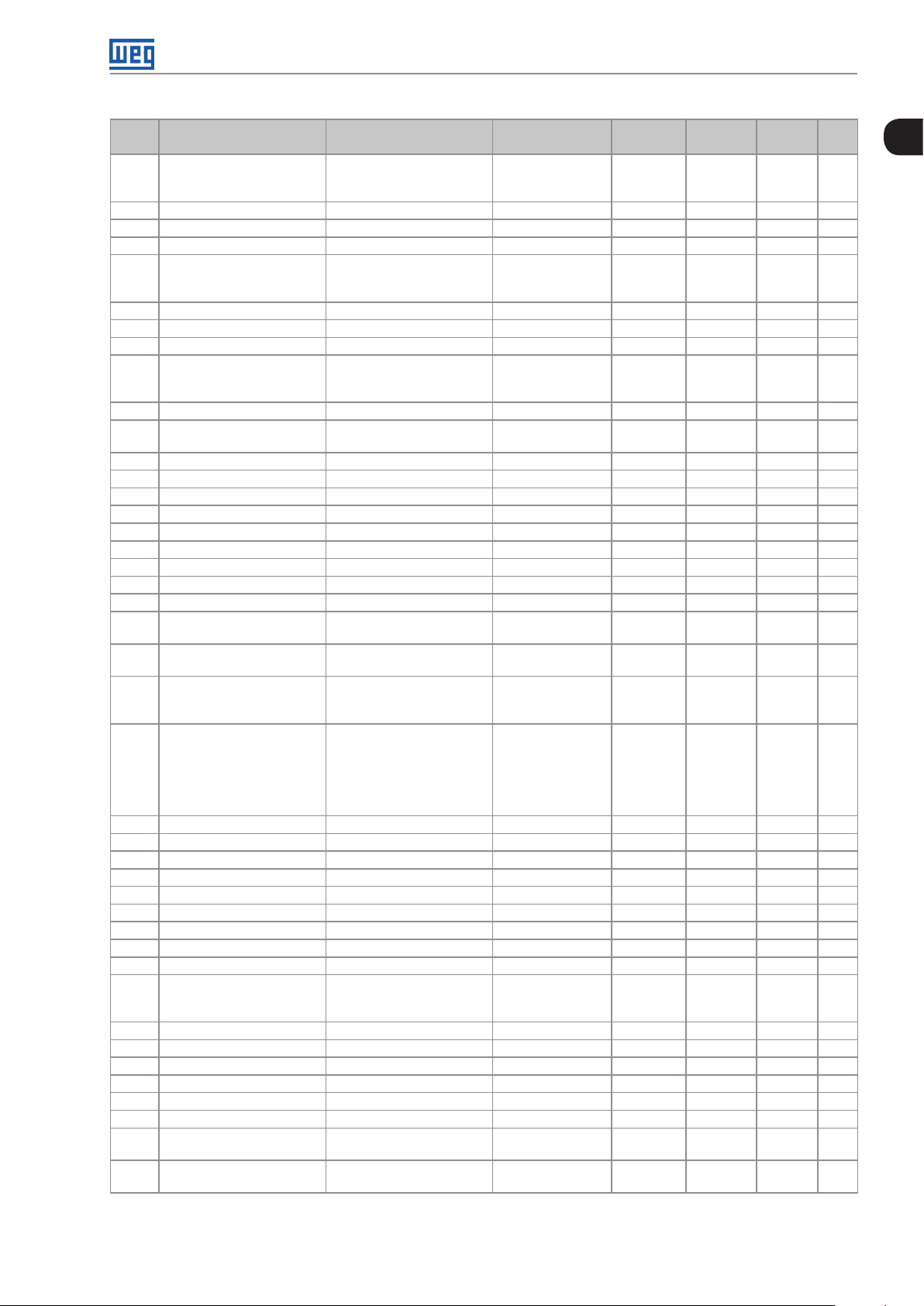
P0161 Speed Prop. Gain 0.0 to 63.9 7.4 Vector 11-12
P0162 Speed Integral Gain 0.000 to 9.999 0.023 Vector 11-12
P0163 LOC Reference Offset -999 to 999 0 Vector 11-13
P0164 REM Reference Offset -999 to 999 0 Vector 11-13
P0165 Speed Filter 0.012 to 1.000 s 0.012 s Vector 11-13
P0166 Speed Diff. Gain 0.00 to 7.99 0.00 Vector 11-14
P0167 Current Prop. Gain 0.00 to 1.99 0.50 Vector 11-14
P0168 Current Integral Gain 0.000 to 1.999 0.010 Vector 11-14
P0169 Max. + Torque Curr. 0.0 to 350.0 % 125.0 % Vector 11-20
P0170 Max. - Torque Curr. 0.0 to 350.0 % 125. 0 % Vector 11- 2 0
P0175 Flux Proport. Gain 0.0 to 31.9 2.0 Vector 11-14
P0176 Flux Integral Gain 0.000 to 9.999 0.020 Vector 11-15
P0178 Rated Flux 0 to 120 % 100 % Vector 11-15
P0180 Iq* After I/f 0 to 350 % 10 % Sless 11-16
P0182 Speed for I/f Activ. 0 to 90 rpm 18 rpm Sless 11-16
P0183 Current in I/f Mode 0 to 9 1 Sless 11-16
P0184 DC Link Regul. Mode 0 = With losses
P0185 DC Link Regul. Level 339 to 1000 V 800 V Vector 11- 2 3
P0186 DC Link Prop. Gain 0.0 to 63.9 26.0 Vector 11- 2 3
P0187 DC Link Integral Gain 0.000 to 9.999 0.010 Vector 11- 2 3
P0190 Max. Output Voltage 0 to 600 V 440 V Vector 11-15
P0200 Password 0 = Inactive
P0202 Control Type 0 = V/f 60 Hz
P0204 Load/Save Parameters 0 = Not Used
P0205 Main Display Parameter Sel. 0 to 1199 2 HMI 5-3
P0206 Secondary Display
Parameter Sel.
P0208 Main Display Scale Factor 0.1 to 1000.0 % 100.0 % HMI 5-3
Adjustable
Range
1 = Class 10
2 = Class 15
3 = Class 20
4 = Class 25
5 = Class 30
6 = Class 35
7 = Class 40
8 = Class 45
1 = Saturated
1 = Without losses
2 = Enab/Disab DIx
1 = Active
2 = Change Pass.
1 = V/f 50 Hz
2 = V/f Adjustable
3 = V V W
4 = Sensorless
1 = Not Used
2 = Reset P0045
3 = Reset P0043
4 = Reset P0044
5 = Load 60 Hz
6 = Load 50 Hz
7 = Load User 1
8 = Load User 2
9 = Save User 1
10 = Save User 2
0 to 1199 3 HMI 5-3
Factory
Setting
1 cfg 15-5
0 cfg, Vector 11-12
1 cfg, Vector 11- 2 2
1 HMI 5-2
0 cfg 9-5
0 cfg 7-1
User
Setting
Propr. Groups Pág.
0
CFW701 | 0-3
Page 12
Quick Parameter Reference, Faults and Alarms
0
Param. Function
P0209 Main Display Eng. Unit 0 = None
P0210 Main Display Decimal Point 0 = wxyz
P0 211 Secondary Display Scale
Factor
P0 212 Secondary Display Decimal
Point
P0216 HMI Backlighting 0 to 15 15 HMI 5-6
Adjustable
Range
1 = V
2 = A
3 = rpm
4 = s
5 = ms
6 = None
7 = m
8 = None
9 = None
10 = %
11 = °C
12 = None
13 = Hz
14 = None
15 = h
16 = W
17 = kW
18 = None
19 = None
20 = min
21 = °F
22 = bar
23 = mbar
24 = psi
25 = Pa
26 = kPa
27 = MPa
28 = mwc
29 = mca
30 = gal
31 = l
32 = in
33 = ft
34 = m³
35 = ft³
36 = gal/s
37 = gal/min
38 = gal/h
39 = l/s
40 = l/min
41 = l/h
42 = m/s
43 = m/min
44 = m/h
45 = ft/s
46 = ft/min
47 = ft/h
48 = m³/s
49 = m³/min
50 = m³/h
51 = ft³/s
52 = ft³/min
53 = ft³/h
54 = As per P0510
55 = As per P0512
56 = As per P0514
57 = As per P0516
1 = wxy.z
2 = wx.yz
3 = w.xyz
4 = As per P0511
5 = As per P0513
6 = As per P0515
7 = As per P0517
0.1 to 1000.0 % 100.0 % HMI 5-3
See options in P0210 1 HMI 5-4
Factory
Setting
3 HMI 5-5
0 HMI 5-4
User
Setting
Propr. Groups Pág.
0-4 | CFW701
Page 13
Quick Parameter Reference, Faults and Alarms
Param. Function
P0217 Zero Speed Disable 0 = Inactive
P0218 Zero Speed Dis. Out 0 = Ref. or Speed
P0219 Zero Speed Time 0 to 999 s 0 s 12-8
P0220 LOC/REM Selection Src 0 = Always LOC
P0221 LOC Reference Sel. 0 = HMI
P0222 REM Reference Sel. See options in P0221 1 cfg I/O 13-24
P0223 LOC FWD/REV Selection 0 = Forward
P0224 LOC Run/Stop Sel. 0 = I,O Keys
P0225 LOC JOG Selection 0 = Disable
P0226 REM FWD/REV Sel. See options in P0223 4 cfg I/O 13-25
P0227 REM Run/Stop Sel. See options in P0224 1 cfg I/O 13-25
P0228 REM JOG Selection See options in P0225 2 cfg I/O 13-26
P0229 Stop Mode Selection 0 = Ramp to Stop
P0230 Dead Zone (AIs) 0 = Inactive
P0231 AI1 Signal Function 0 = Speed Ref.
P0232 AI1 Gain 0.000 to 9.999 1.000 I/O 13-3
P0233 AI1 Signal Type 0 = 0 to 10 V / 20 mA
P0234 AI1 Off set -100.00 to 100.00 % 0.00 % I/O 13-3
P0235 AI1 Filter 0.00 to 16.00 s 0 .15 s I/O 13-4
P0236 AI2 Signal Function See options in P0231 8 cfg I/O 13-2
Adjustable
Range
1 = Active (N* and N)
2 = Active (N*)
1 = Reference
1 = Always REM
2 = LR Key LOC
3 = LR Key REM
4 = DIx
5 = Serial LOC
6 = Serial REM
7 = SoftPLC LOC
8 = SoftPLC REM
1 = AI1
2 = AI2
3 = AI3
4 = Sum AIs > 0
5 = Sum AIs
6 = Serial
7 = SoftPLC
1 = Reverse
2 = FR Key FWD
3 = FR Key REV
4 = DIx
5 = Serial FWD
6 = Serial REV
7 = SoftPLC FWD
8 = SoftPLC REV
9 = AI2 Polarity
1 = DIx
2 = Serial
3 = SoftPLC
1 = JOG Key
2 = DIx
3 = Serial
4 = SoftPLC
1 = Coast to Stop
2 = Fast Stop
1 = Active
1 = No Ramp Ref.
2 = Max. Torque Cur
3 = SoftPLC
4 = PTC
5 = Main PID Feedback 1
6 = Main PID Feedback 2
7 = Main PID Feedback 3
8 = External PID 1 Feedback
9 = External PID 2 Feedback
1 = 4 to 20 mA
2 = 10 V / 20 mA to 0
3 = 20 to 4 mA
4 = -10 to +10 V
Factory
Setting
0 cfg 12-7
0 12-7
2 cfg I/O 13-24
0 cfg I/O 13-24
2 cfg I/O 13-25
0 cfg I/O 13-25
1 cfg I/O 13-2 6
0 cfg 13-26
0 I/O 13-1
5 cfg I/O 13-2
0 cfg I/O 13-5
User
Setting
Propr. Groups Pág.
0
CFW701 | 0-5
Page 14
Quick Parameter Reference, Faults and Alarms
0
Param. Function
P0237 AI2 Gain 0.000 to 9.999 1.000 I/O 13-3
P0238 AI2 Signal Type See options in P0233 0 cfg I/O 13- 5
P0239 AI2 Offset -100.00 to 100.00 % 0.00 % I/O 13-3
P0240 AI2 Filter 0.00 to 16.00 s 0.15 s I/O 13-4
P0 241 AI3 Signal Function See options in P0231 9 cfg I/O 13-2
P0242 AI3 Gain 0.000 to 9.999 1.000 I/O 13- 3
P0243 AI3 Signal Type 0 = 0 to 20mA
P0244 AI3 Offset -100.00 to 100.00 % 0.00 % I/O 13- 3
P0245 AI3 Filter 0.00 to 16.00 s 0.15 s I/O 13-4
P0246 Frequency Input
Configuration
P0 251 AO1 Function 0 = Speed Ref.
P0252 AO1 Gain 0.000 to 9.999 1.000 I/O 13-7
P0253 AO1 Signal Type 0 = 0 to 10 V / 20 mA
P0254 AO2 Function See options in P0251 17 I/O 13-6
P0255 AO2 Gain 0.000 to 9.999 1.000 I/O 13-7
P0256 AO2 Signal Type See options in P0253 0 cfg I/O 13-8
P0263 DI1 Function 0 = Not Used
P0264 DI2 Function See options in P0263 4 cfg I/O 13 -10
P0265 DI3 Function See options in P0263 0 cfg I/O 13 -10
P0266 DI4 Function See options in P0263 20 cfg I/O 13 -10
P0267 DI5 Function See options in P0263 21 cfg I/O 13 -10
P0268 DI6 Function See options in P0263 22 cfg I/O 13 -10
Adjustable
Range
1 = 4 to 20 mA
2 = 20 to 0 mA
3 = 20 to 4 mA
0 = Off
1 = DI3
2 = DI4
1 = Total Ref.
2 = Real Speed
3 = Torque Cur. Ref
4 = Torque Current
5 = Output Current
6 = Active Current
7 = Output Power
8 = Torque Cur. > 0
9 = Motor Torque
10 = SoftPLC
11 = PTC
12 = Motor Ixt
13 = P0696 Value
14 = P0697 Value
15 = Id* Current
16 = External PID 1 Output
17 = External PID 2 Output
1 = 4 to 20 mA
2 = 10 V / 20 mA to 0
3 = 20 to 4 mA
1 = Run/Stop
2 = General Enable
3 = Fast Stop
4 = FWD/REV
5 = LOC/REM
6 = JOG
7 = SoftPLC
8 = Ramp 2
9 = Speed/Torque
10 = JOG+
11 = JOG12 = No Ext. Alarm
13 = No Ext. Fault
14 = Reset
15 = Disab.FlyStart
16 = DC Link Regul.
17 = Progr. Off
18 = Load User 1
19 = Load User 2
20 = Main PID Aut/Man
21 = External PID 1 Aut/Man
22 = External PID 2 Aut/Man
23 = Bypass Mode
24 = Fire Mode
Factory
Setting
0 cfg I/O 13-5
0 cfg 13-23
16 I/O 13-6
0 cfg I/O 13-8
1 cfg I/O 13 -10
User
Setting
Propr. Groups Pág.
0-6 | CFW701
Page 15
Quick Parameter Reference, Faults and Alarms
Param. Function
P0269 DI7 Function See options in P0263 0 cfg I/O 13 -10
P0270 DI8 Function See options in P0263 0 cfg I/O 13-10
P0275 DO1 Function (RL1) 0 = Not Used
P0276 DO2 Function (RL2) See options in P0275 24 cfg I/O 13 -16
P0277 DO3 Function See options in P0275 0 cfg I/O 13 -16
P0278 DO4 Function See options in P0275 0 cfg I/O 13 -16
P0279 DO5 Function See options in P0275 0 cfg I/O 13 -16
P0281 Fx Frequency 0.0 to 300.0 Hz 4.0 Hz 13-21
P0282 Fx Hysteresis 0.0 to 15.0 Hz 2.0 Hz 13-21
P0287 Nx/Ny Hysteresis 0 to 900 rpm 18 (15) rpm 13-21
P0288 Nx Speed 0 to 18000 rpm 120 (100) rpm 13-21
P0289 Ny Speed 0 to 18000 rpm 1800 (1500) rpm 13-21
P0290 Ix Current 0 to 2xI
P0291 Zero Speed 0 to 18000 rpm 18 (15) rpm 13-22
P0292 N = N* Band 0 to 18000 rpm 18 (15) rpm 13-22
P0293 Tx To r q u e 0 to 200 % 100 % 13-22
P0294 Hx Time 0 to 6553 h 4320 h 13-23
Adjustable
Range
1 = N* > Nx
2 = N > Nx
3 = N < Ny
4 = N = N*
5 = Zero Speed
6 = Is > Ix
7 = Is < Ix
8 = Torque > Tx
9 = Torque < Tx
10 = Remote
11 = Run
12 = Ready
13 = No Fault
14 = No F0070
15 = No F0071
16 = No F0006/21/22
17 = No F0051
18 = No F0072
19 = 4-20 mA OK
20 = P0695 Value
21 = Forward
22 = Ride-Through
23 = Pre-Charge OK
24 = Fault
25 = Enabled Time > Hx
26 = SoftPLC
27 = N>Nx/Nt>Nx
28 = F > Fx (1)
29 = F > Fx (2)
30 = STO
31 = No F0160
32 = No Alarm
33 = No Fault/Alarm
34 = Dry Pump Alarm/Fault
35 = Broken Belt Alarm/Fault
36 = Filter Mainten. Alarm/
Fault
37 = Sleep Mode
38 = Not Used
39 = Drive Bypass Contactor
40 = Mains Bypass
Contactor
41 = Fire Mode
42 = Self-Tuning
nom-ND
Factory
Setting
11 cfg I/O 13 -16
1.0 x I
nom-ND
User
Setting
Propr. Groups Pág.
13-22
0
CFW701 | 0-7
Page 16
Quick Parameter Reference, Faults and Alarms
0
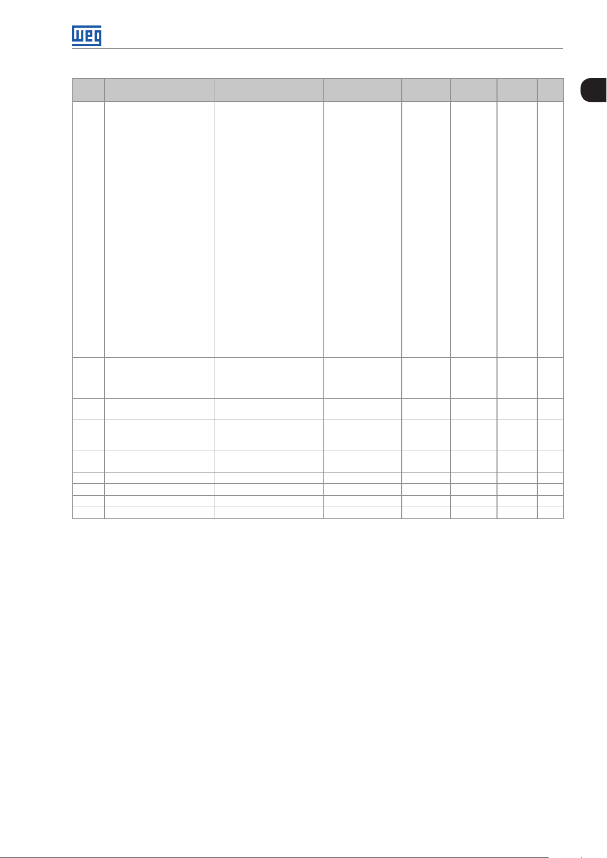
Param. Function
P0295 ND/HD VFD Rated Curr. 0 = 2 A / 2 A
P0296 Line Rated Voltage 0 = 200 / 240 V
P0297 Switching Frequency 0 = 1.25 kHz
P0298 Application 0 = Normal Duty
P0299 DC-Braking Start Time 0.0 to 15.0 s 0.0 s V/f, V V W,
P0300 DC-Braking Stop Time 0.0 to 15.0 s 0.0 s V/f, V V W,
P0301 DC-Braking Speed 0 to 450 rpm 30 rpm V/f, VV W,
P0302 DC-Braking Voltage 0.0 to 10.0 % 2.0 % V/f, V VW 12-18
P0303 Skip Speed 1 0 to 18000 rpm 600 rpm 12-19
Adjustable
Range
1 = 3.6 A / 3.6 A
2 = 5 A / 5 A
3 = 6 A / 5 A
4 = 7 A / 5.5 A
5 = 7 A / 7 A
6 = 10 A / 8 A
7 = 10 A / 10 A
8 = 13 A / 11 A
9 = 13.5 A / 11 A
10 = 16 A / 13 A
11 = 17 A / 13.5 A
12 = 24 A / 19 A
13 = 24 A / 20 A
14 = 28 A / 24 A
15 = 31 A / 25 A
16 = 33.5 A / 28 A
17 = 38 A / 33 A
18 = 45 A / 36 A
19 = 45 A / 38 A
20 = 54 A / 45 A
21 = 58.5 A / 47 A
22 = 70 A / 56 A
23 = 70.5 A / 61 A
24 = 86 A / 70 A
25 = 88 A / 73 A
26 = 105 A / 86 A
27 = 105 A / 88 A
28 = 142 A / 115 A
29 = 180 A / 142 A
30 = 211 A / 180 A
31 = 2.9 A / 2.7 A
32 = 4.2 A / 3.8 A
33 = 7 A / 6.5 A
34 = 10 A / 9 A
35 = 12 A / 10 A
36 = 17 A / 17 A
37 = 22 A / 19 A
38 = 27 A / 22 A
39 = 32 A / 27 A
40 = 44 A / 36 A
41 = 53 A / 44 A
42 = 63 A / 53 A
43 = 80 A / 66 A
44 = 107 A / 90 A
45 = 125 A / 107 A
46 = 150 A / 122 A
1 = 380 V
2 = 400 / 415 V
3 = 440 / 460 V
4 = 480 V
5 = 500 / 525 V
6 = 550 / 575 V
7 = 600 V
1 = 2.5 kHz
2 = 5.0 kHz
3 = 10.0 kHz
4 = 2.0 kHz
1 = Heavy Duty
Factory
Setting
According to
inverter model
According to
inverter model
0 cfg 6-8
User
Setting
Propr. Groups Pág.
ro READ 6-6
cfg 6-7
cfg 6-7
Sless
Sless
Sless
12-16
12-16
12-18
0-8 | CFW701
Page 17
Quick Parameter Reference, Faults and Alarms
Param. Function
P0304 Skip Speed 2 0 to 18000 rpm 900 rpm 12-19
P0305 Skip Speed 3 0 to 18000 rpm 120 0 r pm 12-19
P0306 Skip Band 0 to 750 rpm 0 rpm 12-19
P0308 Serial Address 1 to 247 1 NET 17-1
P0310 Serial Baud Rate 0 = 9600 bits/s
P0 311 Serial Bytes Config. 0 = 8 bits, no, 1
P0 312 Serial Protocol 2 = Modbus RTU
P0 313 Comm. Error Action 0 = Off
P0 314 Serial Watchdog 0.0 to 999.0 s 0.0 s NET 17-1
P0316 Serial Interf. Status 0 = Off
P0317 Oriented Start-up 0 = No
P0 318 Copy Function MMF 0 = Off
P0320 FlyStart/Ride-Through 0 = Off
P0321 DC Link Power Loss 178 to 770 V 505 V Vector 12-14
P0322 DC Link Ride-Through 178 to 770 V 490 V Vector 12-14
P0323 DC Link Power Back 178 to 770 V 535 V Vector 12-14
P0325 Ride-Through P Gain 0.0 to 63.9 22.8 Vector 12-15
P0326 Ride-Through I Gain 0.000 to 9.999 0.12 8 Vector 12-15
P0327 F.S. I/f Current Ramp 0.000 to 1.000 s 0.070 s Sless 12-10
P0328 Flying Start Filter 0.000 to 1.000 s 0.085 s Sless 12-10
P0329 Frequency Ramp F. S. 2.0 to 50.0 20.0 Sless 12-10
P0331 Voltage Ramp 0.2 to 60.0 s 2.0 s V/f, V VW 12-12
P0332 Dead Time 0.1 to 10.0 s 1.0 s V/f, V VW 12-12
P0340 Auto-reset Time 0 to 255 s 0 s 15- 8
P0 3 41 AIPTC Configuration 0 = Off
P0343 Ground Fault Config. 0 = Off
P0344 Current Lim. Conf. 0 = Hold
P0348 Motor Overload Conf. 0 = Off
P0349 Ixt Alarm Level 70 to 100 % 85 % cfg 15-10
Adjustable
Range
1 = 19200 bits/s
2 = 38400 bits/s
3 = 57600 bits/s
4 = Reserved
1 = 8 bits, even, 1
2 = 8 bits, odd, 1
3 = 8 bits, no, 2
4 = 8 bits, even, 2
5 = 8 bits, odd, 2
3 = BACnet
4 = N2
1 = Ramp Stop
2 = General Disab.
3 = Go to LOC
4 = LOC Keep Enab.
5 = Cause Fault
1 = On
2 = Watchdog Error
1 = Yes
1 = VFD → MMF
2 = MMF → VFD
3 = Sync VFD → MMF
4 = Format MMF
5 = Copy SoftPLC Program.
6 = SoftPLC Program Save
1 = Flying Start
2 = FS/RT
3 = Ride-Through
1 = Fault/Alarm
2 = Fault
3 = Alarm
1 = On
1 = Decel.
1 = Fault/Alarm
2 = Fault
3 = Alarm
Factory
Setting
1 NET 17-1
1 NET 17-1
2 NET 17-1
1 NET 17-2
0 cfg STARTUP 7-2
0 cfg 7- 2
0 cfg 12- 8
0 cfg I/O 15-8
1 cfg 15-9
1 cfg, V/f,
1 cfg 15-9
User
Setting
Propr. Groups Pág.
ro NET 17-1
VVW
9-6
0
CFW701 | 0-9
Page 18
Quick Parameter Reference, Faults and Alarms
0
Param. Function
P0350 IGBTs Overload Conf. 0 = F, w/ SF rd.
P0 3 51 Motor Overtemp. Conf. 0 = Off
P0352 Fan Control Config. 0 = HS-OFF, Int-OFF
P0353 IGBTs/Air Overtemp. Cfg 0 = HS-F/A, Air-F/A
P0354 Fan Speed Config. 0 = Inactive
P0355 F0185 Fault Config. 0 = Off
P0356 Dead Time Compens. 0 = Off
P0357 Line Phase Loss Time 0 to 60 s 3 s 15-14
P0360 Speed Hysteresis 0.0 to 100.0 % 10.0 % Vector 11-21
P0361 Time with Speed Different
from Reference
P0372 DC-Braking Curr. Sless 0.0 to 90.0 % 40.0 % Sless 12 -18
P0397 Slip Compens. Regen. 0 = Off
P0398 Motor Service Factor 1.00 to 1.50 1.00 cfg MOTOR 11-7
P0399 Motor Rated Eff. 50.0 to 99.9 % 67. 0 % cfg, V VW MOTOR 10-3
P0400 Motor Rated Voltage 0 to 600 V 440 V cfg MOTOR 11- 8
P0401 Motor Rated Current 0 to 1.3xI
P0402 Motor Rated Speed 0 to 18000 rpm 1750 (1458) rpm cfg MOTOR 11- 8
P0403 Motor Rated Frequency 0 to 300 Hz 60 (50) Hz cfg MOTOR 11- 9
Adjustable
Range
1 = F/A, w/ SF rd.
2 = F, no SF rd.
3 = F/A, no SF rd.
1 = Fault/Alarm
2 = Fault
3 = Alarm
1 = HS-ON, Int-ON
2 = HS-CT, Int-CT
3 = HS-CT, Int-OFF
4 = HS-CT, Int-ON
5 = HS-ON, Int-OFF
6 = HS-ON, Int-CT
7 = HS-OFF, Int-ON
8 = HS-OFF, Int-CT
9 = HS-CT, Int -CT *
10 = HS-CT, Int -OFF *
11 = HS-CT, Int -ON *
12 = HS-ON, Int -CT *
13 = HS-OFF, Int -CT *
1 = HS-F/A, Air-F
2 = HS-F, Air-F/A
3 = HS-F, Air-F
4 = HS-F/A, Air-F/A *
5 = HS-F/A, Air-F *
6 = HS-F, Air-F/A *
7 = HS-F, Air-F *
1 = Fault
1 = On
1 = On
0.0 to 999.0 s 0.0 s Vector 11-22
1 = On
nom-ND
Factory
Setting
1 cfg 15-10
1 cfg 15-11
2 cfg 15-11
0 cfg 15-12
1 cfg 15-13
1 cfg 15-13
1 cfg 15-14
1 cfg, V VW 10-3
1.0 x I
nom-ND
User
Setting
Propr. Groups Pág.
cfg MOTOR 11 - 8
0-10 | CFW701
Page 19
Quick Parameter Reference, Faults and Alarms
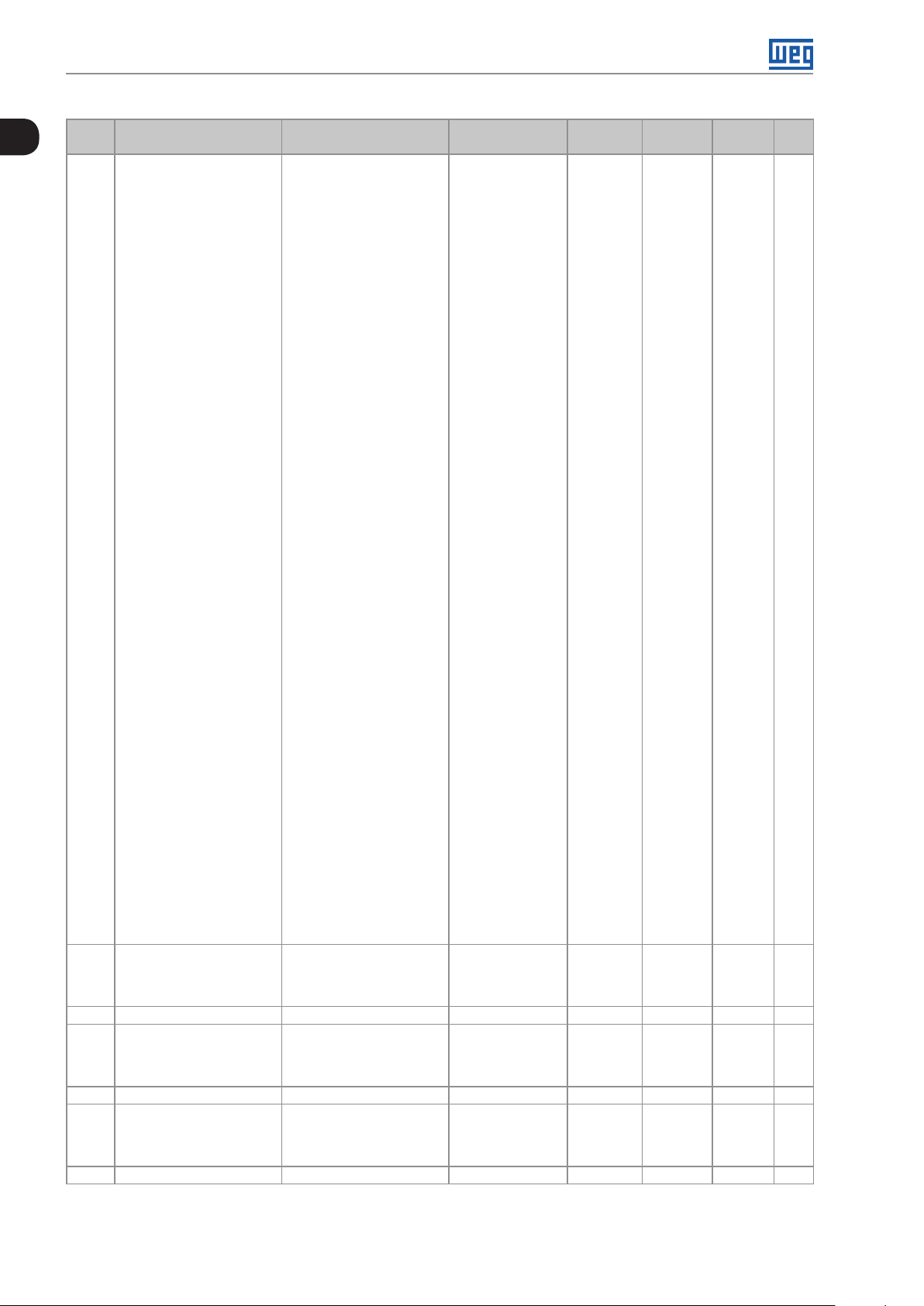
Param. Function
Adjustable
Range
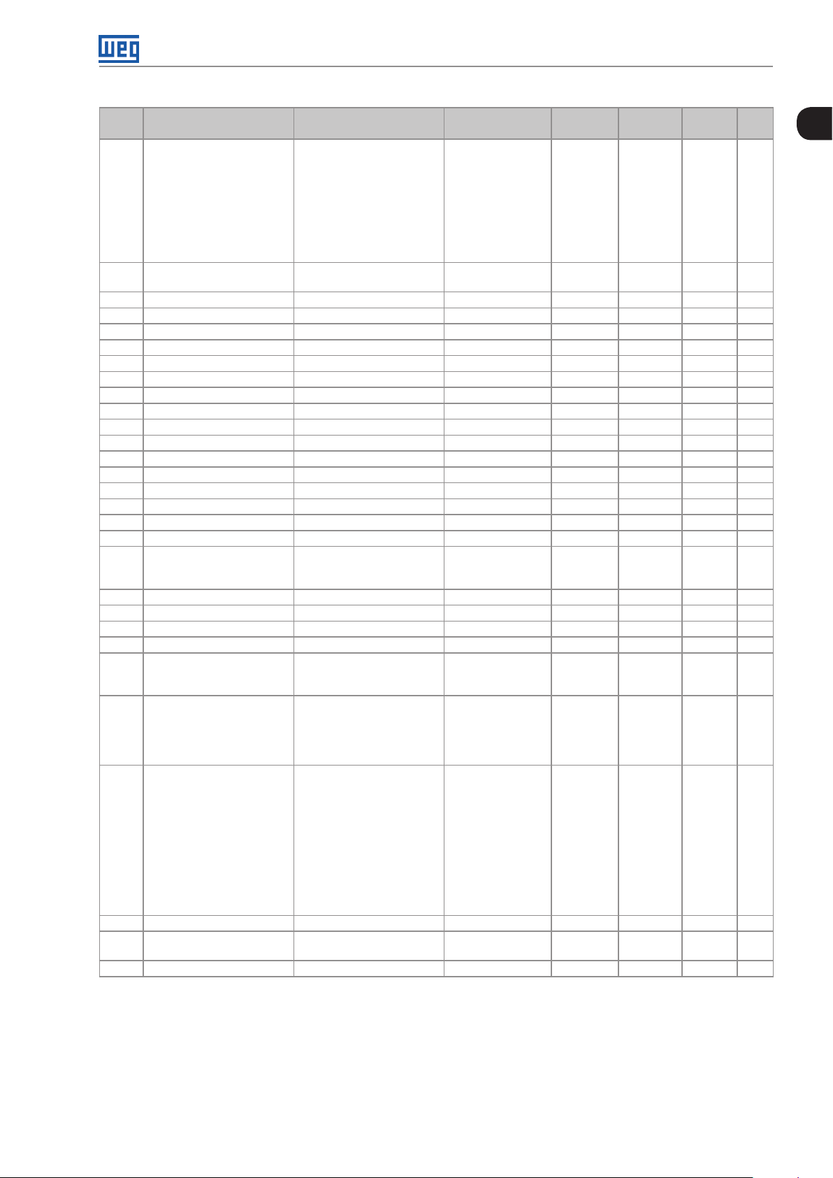
P0404 Motor Rated Power 0 = 0.33 hp / 0.25 kW
1 = 0.5 hp / 0.37 kW
Factory
Setting
Motor
max-ND
User
Setting
Propr. Groups Pág.
cfg MOTOR 11 - 9
2 = 0.75 hp / 0.55 kW
3 = 1 hp / 0.75 kW
4 = 1.5 hp / 1.1 kW
5 = 2 hp / 1.5 kW
6 = 3 hp / 2.2 kW
7 = 4 hp / 3 kW
8 = 5 hp / 3.7 kW
9 = 5.5 hp / 4 kW
10 = 6 hp / 4.5 kW
11 = 7.5 hp / 5.5 kW
12 = 10 hp / 7.5 kW
13 = 12.5 hp / 9 kW
14 = 15 hp / 11 kW
15 = 20 hp / 15 kW
16 = 25 hp / 18.5 kW
17 = 30 hp / 22 kW
18 = 40 hp / 30 kW
19 = 50 hp / 37 kW
20 = 60 hp / 45 kW
21 = 75 hp / 55 kW
22 = 100 hp / 75 kW
23 = 125 hp / 90 kW
24 = 150 hp / 110 kW
25 = 175 hp / 130 kW
P0406 Motor Ventilation 0 = Self-Vent.
0 cfg MOTOR 11-10
1 = Separate Vent.
2 = Optimal Flux
3 = Extended Protection
P0407 Motor Rated Power Fac 0.50 to 0.99 0.68 cfg, V/f,
VVW
P0408 Run Self-Tuning 0 = No
1 = No Rotation
2 = Run for I
m
0 cfg, VV W,
Vector
P0409 Stator Resistance 0.000 to 9.999 Ω 0.000 Ω cfg, V VW,
MOTOR 10-4
19-7
MOTOR 11-17
MOTOR 11-18
Vector
P0 410 Magnetization Current 0 to 1.25xI
nom-ND
I
nom-ND
MOTOR 11-18
P0 411 Leakage Inductance 0.00 to 99.99 mH 0.00 mH cfg, Vector MOTOR 11-19
P0 412 Tr Time Constant 0.000 to 9.999 s 0.000 s Vector MOTOR 11-19
P0 413 Tm Time Constant 0.00 to 99.99 s 0.00 s Vector MOTOR 11- 2 0
0
CFW701 | 0-11
Page 20
Quick Parameter Reference, Faults and Alarms
0
Param. Function
P0 510 Ind. Eng. Unit 1 0 = None
P0 511 Ind. Decimal Point 1 0 = wxyz
P0 512 Ind. Eng. Unit 2 See options in P0510 11 HMI 5-9
P0 513 Ind. Decimal Point 2 0 = wxyz
P0 514 Ind. Eng. Unit 3 See options in P0510 10 HMI 5 -11
P0 515 Ind. Decimal Point 3 0 = wxyz
P0 516 Ind. Eng. Unit 4 See options in P0510 13 HMI 5-13
Adjustable
Range
1 = V
2 = A
3 = rpm
4 = s
5 = ms
6 = None
7 = m
8 = None
9 = None
10 = %
11 = °C
12 = None
13 = Hz
14 = None
15 = h
16 = W
17 = kW
18 = None
19 = None
20 = min
21 = °F
22 = bar
23 = mbar
24 = psi
25 = Pa
26 = kPa
27 = MPa
28 = mwc
29 = mca
30 = gal
31 = l
32 = in
33 = ft
34 = m³
35 = ft³
36 = gal/s
37 = gal/min
38 = gal/h
39 = l/s
40 = l/min
41 = l/h
42 = m/s
43 = m/min
44 = m/h
45 = ft/s
46 = ft/min
47 = ft/h
48 = m³/s
49 = m³/min
50 = m³/h
51 = ft³/s
52 = ft³/min
53 = ft³/h
1 = wxy.z
2 = wx.yz
3 = w.xyz
1 = wxy.z
2 = wx.yz
3 = w.xyz
1 = wxy.z
2 = wx.yz
3 = w.xyz
Factory
Setting
22 HMI 5-7
1 HMI 5-8
1 HMI 5 -10
1 HMI 5 -12
User
Setting
Propr. Groups Pág.
0-12 | CFW701
Page 21
Quick Parameter Reference, Faults and Alarms
Param. Function
P0517 Ind. Decimal Point 4 0 = wxyz
P0579 Reference to Fire Mode 0 to 18000 rpm 1800 (1500) rpm HVAC 19-2
P0580 Fire Mode Configuration 0 = Disabled
P0581 Fire Mode PID Setpoint -32768 to 32767 0 HVAC 19-3
P0582 Auto-reset Configuration 0 = Limited
P0583 Bypass Mode Configuration 0 = Off
P0584 Bypass Contactor Time 0.00 to 300.00 s 0.30 s HVAC 19-7
P0585 Short Cycle Protection
Config.
P0586 Minimum RUN Time 0.00 to 650.00 s 5.00 s HVAC 19-9
P0587 Minimum STOP Time 0.00 to 650.00 s 5.00 s HVAC 19-9
P0588 Maximum Torque Level 0 to 85 % 0 % cfg, V/f HVAC 19- 8
P0589 Energy Saving Min. Mag. 40 to 80 % 40 % cfg, V/f HVAC 19-8
P0590 Energy Saving Min. Speed 0 to 18000 rpm 600 (525) rpm cfg, V/f HVAC 19-8
P0591 Energy Saving Histeresis 0 to 30 % 10 % cfg, V/f HVAC 19-8
P0680 Logical Status Bit 0 = Not Used
P0681 Speed in 13 bits -32768 to 32767 ro READ,
P0682 Serial Control Word Bit 0 = Ramp Enable
P0683 Serial Speed Ref. -32768 to 32767 ro READ,
P0695 DOx Value Bit 0 = DO1
P0696 AOx Value 1 -32768 to 32767 0 NET 17-2
P0697 AOx Value 2 -32768 to 32767 0 NET 17- 2
P0760 BACnet Dev Inst High 0 to 419 0 NET 17-1
P0761 BACnet Dev Inst Low 0 to 9999 0 NET 17-1
P0762 Max. Number of Master 0 to 127 127 NET 17-1
P0763 MS/TP Max. Info Frame 1 to 65535 1 NET 17-1
Adjustable
Range
1 = wxy.z
2 = wx.yz
3 = w.xyz
1 = Enabled
2 = Enabled/P0579
3 = Enabled/P0581
4 = Enabled/Gen. Disable
1 = Unlimited
1 = On/DIx
2 = On/DIx+Fault
0 = Off
1 = On
Bit 1 = Run Command
Bit 2 = Fire Mode
Bit 3 = Bypass
Bit 4 = Quick Stop ON
Bit 5 = 2nd Ramp
Bit 6 = Config. Mode
Bit 7 = Alarm
Bit 8 = Running
Bit 9 = Enabled
Bit 10 = Forward
Bit 11 = JOG
Bit 12 = Remote
Bit 13 = Subvoltage
Bit 14 = Not Used
Bit 15 = Fault
Bit 1 = General Enable
Bit 2 = Run Forward
Bit 3 = JOG Enable
Bit 4 = Remote
Bit 5 = 2nd Ramp
Bit 6 = Quick Stop
Bit 7 = Fault Reset
Bit 8 to 12 = Reserved
Bit 13 = Internal PID
Bit 14 = External PID 1
Bit 15 = External PID 2
Bit 1 = DO2
Bit 2 = DO3
Bit 3 = DO4
Bit 4 = DO5
Factory
Setting
1 HMI 5 -14
0 cfg HVAC 19-3
0 cfg HVAC 19-3
0 cfg HVAC 19-6
0 cfg HVAC 19-9
Bit 4 NET 17-2
User
Setting
Propr. Groups Pág.
ro RE AD,
NET
NET
ro RE AD,
NET
NET
17-2
17-2
17-1
17-2
17-1
17-2
0
CFW701 | 0-13
Page 22
Quick Parameter Reference, Faults and Alarms
0
Param. Function
P0764 I-AM Msg Transmition 0 = Power Up
P0765 Token RX Qtde 0 to 65535 ro READ,
P1000 SoftPLC Status 0 = No Application
P1001 SoftPLC Command 0 = Stop Application
P1002 Scan Cycle Time 0.0 to 999.9 ms ro RE AD,
P1003 SoftPLC Appl. Sel. 0 = User
P1010 Version of the HVAC
Application
P10 11 Main PID Aut. Setpoint -32768 to 32767 0 HVAC 19 -14
P1012 SoftPLC Parameter 3 -32768 to 32767 0 HVAC 18-2
P1013 SoftPLC Parameter 4 -32768 to 32767 0 HVAC 18-2
P1014 Main PID Man. Setpoint 0.0 to 100.0 % 0.0 % HVAC 19-14
P1015 Main PID Process Variable -32768 to 32767 ro RE AD,
P1016 MainPID Output 0.0 to 100.0 % ro RE AD,
P1017 MainPID Act. Control 0 = Disable PID
P1018 Main PID Operation Mode 0 = AlwaysAutomatic
P1019 Main PID Sampling Time 0.10 to 60.00 s 0 .1 0 s HVAC 19 -16
P1020 Main PIDP. Gain 0.000 to 32.767 1.000 HVAC 19 -17
P1021 Main PIDI. Gain 0.000 to 32.767 0.430 HVAC 19 -17
P102 2 Main PIDD. Gain 0.000 to 32.767 0.000 HVAC 19 -17
P1023 Main PID Output Min. Value 0.0 to 100.0 % 0.0 % HVAC 19 -17
P1024 Main PID Output Max. Value 0.0 to 100.0 % 100.0 % HVAC 19 -18
P1025 SoftPLC Parameter 16 -32768 to 32767 0 HVAC 18-2
P1026 Main PID Feedback Conf. 0 = Sum Feed. 1, 2 and 3
P1027 Main PID Min. Feedback -32768 to 32767 0 HVAC 19-18
P1028 Main PID Max. Feedback -32768 to 32767 1000 H VAC 19-19
P102 9 SoftPLC Parameter 20 -32768 to 32767 0 HVAC 18-2
P1030 Main PID Fdbck Alarms
Conf.
P1031 M. PID Fdbck Alarm Low V. -32768 to 32767 50 HVAC 19 -20
P1032 M. PID Fdbck Alarm Low T. 0.00 to 650.00 s 5.00 s HVAC 19-20
P1033 M. PID Fdbck Alarm High V. -32768 to 32767 900 H VAC 19 -20
P1034 M. PID Fdbck Alarm Hig T. 0.00 to 650.00 s 5.00 s HVAC 19-21
P1035 SoftPLC Parameter 26 -32768 to 32767 0 HVAC 18-2
P1036 Sleep Mode Speed 0 to 18000 350 HVAC 19 -21
P1037 Sleep Mode Time 0.00 to 650.00 s 5.00 s HVAC 19-22
P1038 Wake Up Main Deviation 0.0 to 100.0 % 5.0 % HVAC 19-22
P1039 Wake Up Main Time 0.00 to 650.00 s 10.0 0 s HVAC 19 -22
P1040 HVAC Fun. Log. Status 0000h to FFFFh ro RE AD,
P10 41 SoftPLC Parameter 32 -32768 to 32767 0 HVAC 18-2
Adjustable
Range
1 = Continuos
1 = Install. App.
2 = Incompat. App.
3 = App. Stopped
4 = App. Running
1 = Run Application
2 = Delete Application
1 = HVAC
0.00 to 10.00 ro HVAC 19- 39
1 = Direct Mode
2 = Reverse Mode
1 = Always Manual
2 = A/M DI w/o bumpless
3 = A/M Net w/o bumpless
4 = A/M DI w/ bumpless
5 = A/M Net w/ bumpless
1 = Difference Feed. 1 and 2
2 = Average Feed. 1, 2 and 3
3 = Minimum Feed. 1, 2 and 3
4 = Maximum Feed. 1, 2 and 3
0 = Disable
1 = Enable Alarm
2 = Enable Fault
Factory
Setting
0 NET 17-1
1 HVAC 18-1
1 cfg HVAC 18-2
0 cfg HVAC 19 -15
0 HVAC 19 -16
0 cfg HVAC 19 -18
0 HVAC 19-19
User
Setting
Propr. Groups Pág.
NET
ro RE AD,
HVAC
HVAC
HVAC
HVAC
HVAC
17-1
18 -1
18 -1
19 -14
19 -15
19- 38
0-14 | CFW701
Page 23
Quick Parameter Reference, Faults and Alarms
Param. Function
P1042 Dry Pump Config. 0 = Disable
P1043 Dry Pump Speed 0 to 18000 400 HVAC 19-10
P1044 Dry Pump Torque 0.0 to 350.0 % 20.0 % HVAC 19 -10
P1045 Dry Pump Time 0.00 to 650.00 s 20.00 s HVAC 19 -11
P1046 Broken Belt Config. 0 = Disable
P1047 Broken Belt Speed 0 to 18000 400 HVAC 19 -11
P1048 Broken Belt Torque 0.0 to 350.0 % 20.0 % HVAC 19 -12
P1049 Broken Belt Time 0.00 to 650.00 s 20.00 s HVAC 19 -12
P1050 Filter Mainten. Alarm Conf. 0 = Disable
P10 51 Filter Mainten. Alarm Time 0 to 32000 h 5000 h HVAC 19-13
P1052 Filter Mainten. Alarm
Counter
P1053 SoftPLC Parameter 44 -32768 to 32767 0 HVAC 18-2
P1054 SoftPLC Parameter 45 -32768 to 32767 0 HVAC 18-2
P1055 SoftPLC Parameter 46 -32768 to 32767 0 HVAC 18-2
P1056 SoftPLC Parameter 47 -32768 to 32767 0 HVAC 18-2
P1057 SoftPLC Parameter 48 -32768 to 32767 0 HVAC 18-2
P1058 SoftPLC Parameter 49 -32768 to 32767 0 HVAC 18-2
P1059 SoftPLC Parameter 50 -32768 to 32767 0 HVAC 18-2
P1060 Ext. PID 1 Aut. Setpoint -32768 to 32767 0 HVAC 19-24
P1061 Ext. PID 1 Man. Setpoint 0.0 to 100.0 % 0.0 % HVAC 19 -24
P1062 Ext. PID 1 Feedback -32768 to 32767 ro READ,
P1063 Ext. PID 1 Output 0.0 to 100.0 % ro RE AD,
P1064 Ext. PID 1 Act. Control 0 = Disable PID
P1065 Ext. PID 1 Operation Mode 0 = AlwaysAutomatic
P1066 Ext. PID 1 Sampling Time 0.10 to 60.00 s 0.10 s HVAC 19-27
P1067 Ext. PID 1 P. Gain 0.000 to 32.767 1.000 HVAC 19-27
P1068 Ext. PID 1 I. Gain 0.000 to 32.767 0.430 HVAC 19-27
P1069 Ext. PID 1 D. Gain 0.000 to 32.767 0.000 HVAC 19-27
P1070 Ext. PID 1 Output Min. Value 0.0 to 100.0 % 0.0 % HVAC 19 -28
P1071 Ext. PID 1 Output Max. Value 0.0 to 100.0 % 100.0 % HVAC 19 -28
P1072 SoftPLC Parameter 63 -32768 to 32767 0 HVAC 18-2
P1073 Ext. PID 1 Min. Feedback -32768 to 32767 0 HVAC 19-28
P1074 Ext. PID 1 Max. Feedback -32768 to 32767 1000 HVAC 19 -28
P1075 Ext. PID 1 Fdbck Alarms
Conf.
P1076 Ext. PID 1 Fdbck Alarm Low V. -32768 to 32767 2 HVAC 19-29
P1077 Ext. PID 1 Fdbck Alarm Low T. 0.00 to 650.00 s 5.00 s HVAC 19-3 0
P1078 Ext. PID 1 Fdbck Alarm High V. -32768 to 32767 900 HVAC 19-3 0
P1079 Ext. PID 1 Fdbck Alarm Hig T. 0.00 to 650.00 s 5.00 s HVAC 19 -30
P1080 Ext. PID 2 Aut. Setpoint -32768 to 32767 0 HVAC 19-31
P1081 Ext. PID 2 Man. Setpoint 0.0 to 100.0 % 0.0 % HVAC 19-32
P1082 Ext. PID 2 Feedback -32768 to 32767 ro READ,
P1083 Ext. PID 2 Output 0.0 to 100.0 % ro READ,
Adjustable
Range
1 = Enable Alarm
2 = Enable Fault
1 = Enable Alarm
2 = Enable Fault
1 = Enable Alarm
2 = Enable Fault
0 to 32000 h ro READ,
1 = Direct Mode
2 = Reverse Mode
1 = Always Manual
2 = A/M DI w/o bumpless
3 = A/M Net w/o bumpless
4 = A/M DI w/ bumpless
5 = A/M Net w/ bumpless
0 = Disable
1 = Enable Alarm
2 = Enable Fault
Factory
Setting
0 cfg HVAC 19 -10
0 cfg HVAC 19 -11
0 cfg HVAC 19 -12
0 cfg HVAC 19 -25
0 HVAC 19-26
0 HVAC 19-29
User
Setting
Propr. Groups Pág.
HVAC
HVAC
HVAC
HVAC
HVAC
19 -13
19-25
19-25
19- 32
19- 32
0
CFW701 | 0-15
Page 24
Quick Parameter Reference, Faults and Alarms
0
Param. Function
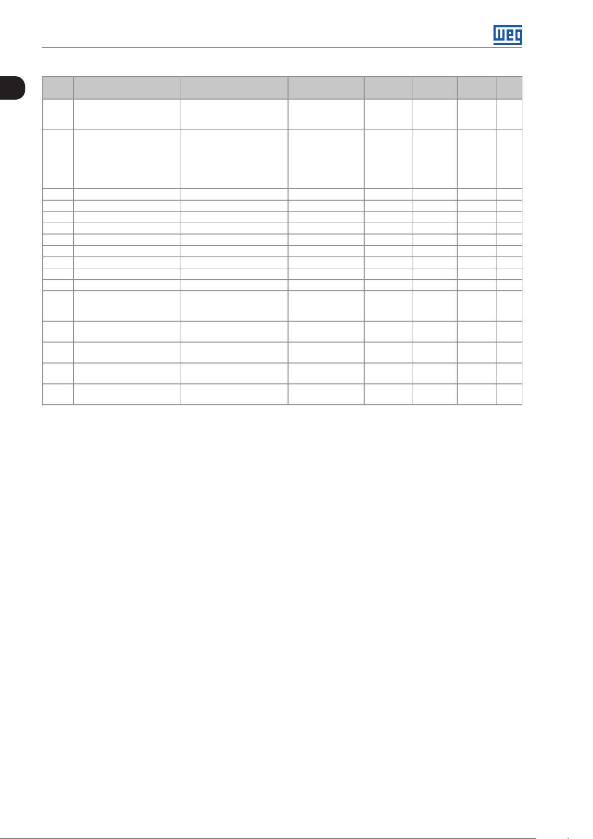
P1084 Ext. PID 2 Act. Control 0 = Disable PID
P1085 Ext. PID 2 Operation Mode 0 = AlwaysAutomatic
P1086 Ext. PID 2 Sampling Time 0.10 to 60.00 s 0.10 s HVAC 19-3 4
P1087 Ext. PID 2 P. Gain 0.000 to 32.767 1.000 HVAC 19 - 34
P1088 Ext. PID 2 I. Gain 0.000 to 32.767 0.430 HVAC 19 -34
P1089 Ext. PID 2 D. Gain 0.000 to 32.767 0.000 HVAC 19-35
P1090 Ext. PID 2 Output Min. Value 0.0 to 100.0 % 0.0 % HVAC 19-35
P1091 Ext. PID 2 Output Max. Value 0.0 to 100.0 % 100.0 % HVAC 19-35
P1092 SoftPLC Parameter 83 -32768 to 32767 0 HVAC 18-2
P1093 Ext. PID 2 Min. Feedback -32768 to 32767 0 HVAC 19-35
P1094 Ext. PID 2 Max. Feedback -32768 to 32767 1000 HVAC 19- 36
P1095 Ext. PID 2 Fdbck Alarms
Conf.
P1096 Ext. PID 2 Fdbck Alarm
Lo w V.
P1097 Ext. PID 2 Fdbck Alarm
Low T.
P1098 Ext. PID 2 Fdbck Alarm
High V.
P1099 Ext. PID 2 Fdbck Alarm
Hig T.
Adjustable
Range
1 = Direct Mode
2 = Reverse Mode
1 = Always Manual
2 = A/M DI w/o bumpless
3 = A/M Net w/o bumpless
4 = A/M DI w/ bumpless
5 = A/M Net w/ bumpless
0 = Disable
1 = Enable Alarm
2 = Enable Fault
-32768 to 32767 2 HVAC 19-37
0.00 to 650.00 s 5.00 s HVAC 19 -37
-32768 to 32767 900 HVAC 19-37
0.00 to 650.00 s 5.00 s HVAC 19-38
Factory
Setting
0 cfg HVAC 19-32
0 HVAC 19-3 3
0 HVAC 19-3 6
User
Setting
Propr. Groups Pág.
Notes:
ro = Read-only parameter
rw = Reading/writing parameter
cfg = Configuration parameter, it can be changed only with stopped motor
V/f = Parameter available in V/f mode
Adj = Parameter available only in adjustable V/f mode
VVW = Parameter available in VV W mode
Vector = Parameter available in vector mode
Sless = Parameter available only in sensorless mode
0-16 | CFW701
Page 25
Quick Parameter Reference, Faults and Alarms
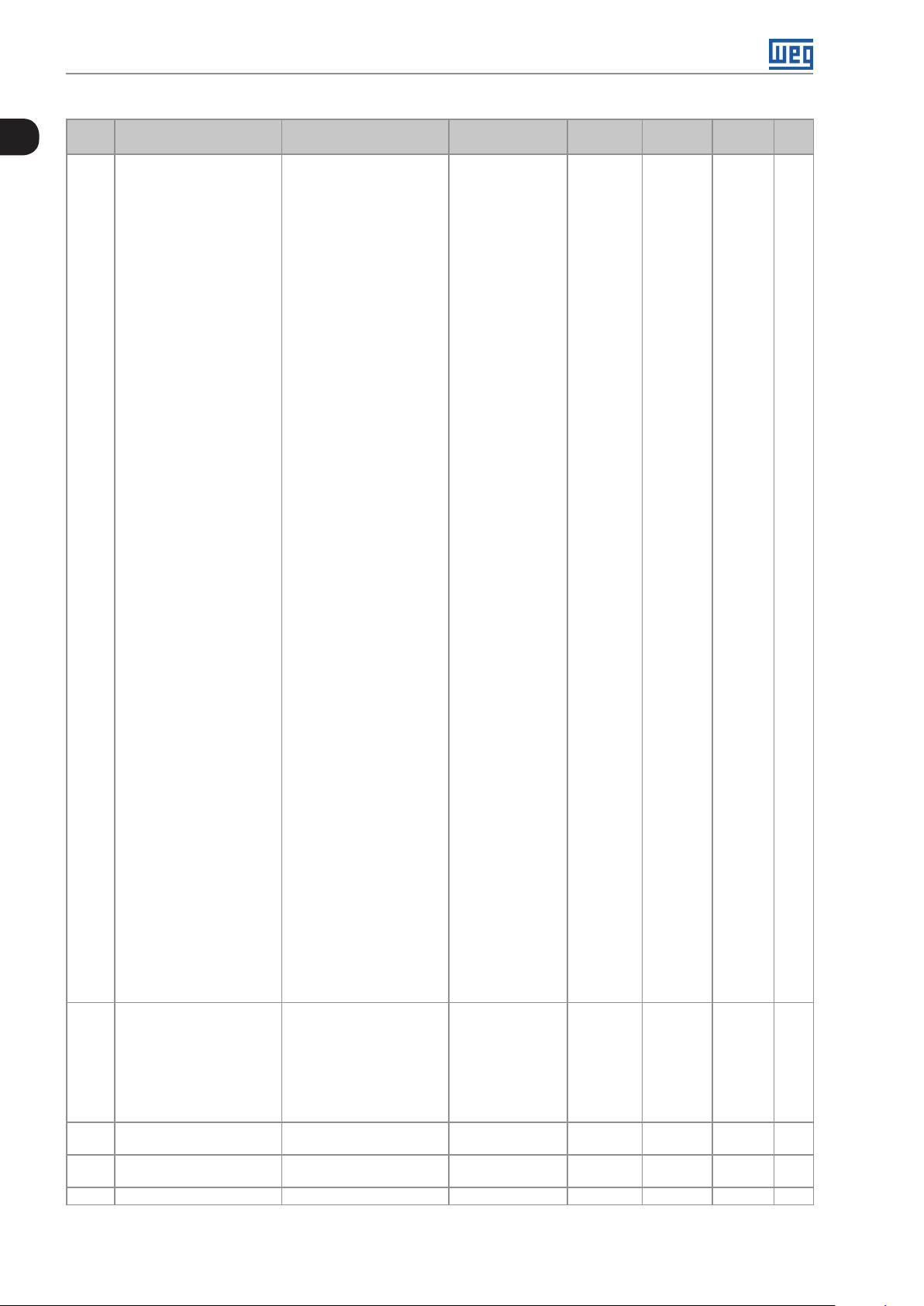
Fault/Alarm Description Possible Causes
F0006:
Input Voltage Imbalance
or Phase Loss
The mains voltage imbalance is too high or phase
loss at the supply line has occurred.
Note:
A Phase Loss at the inverter input.
The input voltage imbalance is > 5 %.
- This fault may not occur if the load at the motor
shaft is too low or nonexistent.
P0357 sets the time for the trip, and P0357 = 0
disables this fault.
F0 021:
DC Link Undervoltage
A DC link undervoltage condition has occurred. The input voltage is too low and the DC link voltage
dropped below the minimum permitted value (monitor
the P0004 parameter value):
Ud < 223 V - 200 / 240 V three-phase input voltage;
Ud < 170 V - 200 / 240 V single-phase input voltage
(CFW701XXXXS2 or CFW701XXXXB2 models)
(P0296 = 0);
Ud < 385 V - 380 V input voltage (P0296 = 1);
Ud < 405 V - 400 / 415 V input voltage (P0296 = 2);
Ud < 446 V - 440 / 460 V input voltage (P0296 = 3);
Ud < 487 V - 480 V input voltage (P0296 = 4);
Ud < 530 V - input voltage 500 / 525 V (P0296 = 5);
Ud < 580 V - input voltage 550 / 575 V (P0296 = 6);
Ud < 605 V - input voltage 600 V (P0296 = 7).
Phase loss at the inverter input.
Pre-charge circuit failure.
Parameter P0296 was set to a value higher than the
power supply rated voltage.
F0022:
DC Link Overvoltage
A DC link overvoltage condition has occurred. Too high input voltage, resulting in a DC link voltage higher
than the maximum permitted value:
Ud > 400 V - 220 / 230 V models (P0296 = 0);
Ud > 800 V - 380 / 480 V models (P0296 = 1, 2, 3, or 4);
Ud > 1000 V - 500 / 600 V models (P0296 = 5, 6 or 7).
The inertia of the driven-load is too high or the
deceleration time is too short.
The parameter P0151, P0153 or P0185 setting is too high.
A0046:
High Load at the Motor
A0 047:
IGBT Overload Alarm
It is the motor overload alarm.
Note:
It can be disabled by setting P0348 = 0 or 2.
It is the IGBT overload alarm.
Note:
The settings of P0156, P0157 and P0158 are too low for
the used motor.
There is excessive load at the motor shaft.
The inverter output current is too high.
It can be disabled by setting P0350 = 0 or 2.
F0048:
It is the IGBT overload fault. The inverter output current is too high.
IGBT Overload Fault
A0050:
IGBT High Temperature
F0 051:
IGBT Overtemperature
F0070:
Overcurrent/
Short-circuit
F0 071:
Output Overcurrent
F0072:
Motor Overload
F0 0 74:
Ground Fault
The NTC temperature sensors located in the
IGBTs detected a high temperature alarm.
Note:
It can be disabled by setting P0353 = 2 or 3.
High surrounding air temperature (>50 °C (122 °F)) and
high output current.
Blocked or defective fan.
Very dirty heatsink.
The NTC temperature sensors located in the
IGBTs detected a high temperature fault.
An overcurrent or a short-circuit at the output,
at the DC link or at the braking resistor, has
occurred.
Short-circuit between two motor phases.
Short-circuit between the dynamic braking resistor
connection cables.
Shorted IGBT modules.
An output overcurrent has occurred. Excessive load inertia or too short acceleration ramp.
P0135, or P0169 and P0170 settings are too high.
The motor overload protection has tripped.
Note:
It can be disabled by setting P0348 = 0 or 3.
A ground fault occurred either in the cable
between the inverter and the motor or in the
motor itself.
The settings of P0156, P0157 and P0158 are too low for
the used motor.
There is excessive load at the motor shaft.
Short-circuit to the ground in one or more output phases.
Motor cable capacitance is too large, resulting in current
peaks at the output.
Note:
It can be disabled by setting P0343 = 0.
F0078:
Motor Overtemperature
Fault related to the PTC temperature sensor
installed in the motor.
Note:
- It can be disabled by setting P0351 = 0 or 3.
- An analog input and an analog output must be
set for the PTC function.
Excessive load at the motor shaft.
Severe duty cycle (too many starts / stops per minute).
Too high surrounding air temperature.
Loose connection or short-circuit (resistance < 100 Ω) in
the wiring connected to the motor thermistors.
Not installed motor thermistors.
Blocked motor shaft.
0
CFW701 | 0-17
Page 26
Quick Parameter Reference, Faults and Alarms
0
Fault/Alarm Description Possible Causes
F0080:
Microcontroller watchdog fault. Electrical noise.
CPU Watchdog
F0084:
Auto-Diagnosis Fault
A0090:
External Alarm
Auto-Diagnosis Fault. Defect in the inverter internal circuitry.
Firmware incompatible with an accessory.
External alarm monitored through a digital input.
Note:
A digital input (DI1 to DI8) programmed for “No external
alarm” is open.
It is necessary to program a digital input for “No
external alarm”.
F0 091:
External Fault
External fault monitored through a digital input.
Note:
A digital input (DI1 to DI8) programmed for “No external
fault” is open.
It is necessary to program a digital input for “No
external fault”.
A0098:
Activate General Enable
F0099:
Invalid Current Offset
A0110 :
High Motor Temperature
General Enable signal is missing during the
self-tuning.
The current measurement circuit is presenting an
abnormal value for null current.
Fault detected through PTC type temperature
sensors installed in the motor.
Note:
- It can be disabled by setting P0351 = 0 or 2.
- An analog input and an analog output must be
The digital input programmed for “General Enable” is
open.
Defect in the inverter internal circuitry.
Excessive load at the motor shaft.
Severe duty cycle (too many starts / stops per minute).
Too high surrounding air temperature.
Not installed motor thermistors.
Blocked motor shaft.
set for the PTC function.
A0128:
Serial Communication
Timeout
It indicates that the inverter stopped receiving
valid telegrams during a certain period.
Note:
Check the wiring and the ground installation.
Make sure that the inverter has sent a new message
within the time interval set at P0314.
It can be disabled by setting P0314 = 0.0 s
F0150:
Motor Overspeed
Overspeed fault.
It trips when the actual speed exceeds the value
(100 % + P0132)
of
P0134 x
100%
for more than 20 ms.
Wrong settings of P0161 and/or P0162.
Problem with a hoist-type load.
F0151:
FLASH Memory Module
Fault
A0152:
High Internal Air
Temperature
F0153:
Internal Air
Overtemperature
F0156:
Undertemperature
F0 15 7:
Parameter Table Data
Loss
F0158:
Parameter Table Fault
A0159:
Incompatible HMI
F016 0:
Safety Stop Relays
A016 3:
AI1 Broken Cable
A016 4:
AI2 Broken Cable
A016 5:
AI3 Broken Cable
A016 8:
Speed Error too High
0-18 | CFW701
FLASH Memory Module (MMF-01) fault. Defective FLASH memory module.
Check the connection of the FLASH memory module.
This alarm indicates that the internal air
temperature is too high.
Note:
It can be disabled by setting P0353 = 1 or 3.
High surrounding air temperature (>50 °C (122 °F)) and
high output current.
Defective internal fan (if existent).
High temperature (> 45 ºC) inside the cabinet.
It indicates internal air overtemperature fault. High surrounding air temperature (>50 °C (122 °F)) and
high output current.
Defective internal fan (if existent).
The temperature sensors located in the IGBTs or
Surrounding air temperature ≤ -30 °C (-22 °F).
in the rectifier detected a low temperature, below
-30 °C ( -22 °F), fault.
There was a problem during the initialization,
during the parameter table loading routine. Some
The control was switched off very fast while a parameter
was being modified.
recent parameter modifications may have been
lost.
There was a problem during the initialization,
during the parameter table loading routine. All
Firmware updating fault.
Defective control board.
the parameters were lost and the factory settings
were loaded.
Incompatible HMI HMI of another product being used.
Safety stop relay fault. One of the relays is defective or it does not have +24 V
applied to its coil.
It indicates that the AI1 current (4-20 mA or
20-4 mA) reference is out of the 4 to 20 mA range.
Broken AI1 cable.
Bad contact at the connection of the signal to the
terminal strip.
It indicates that the AI2 current (4-20 mA or
20-4 mA) reference is out of the 4 to 20 mA range.
Broken AI2 cable.
Bad contact at the connection of the signal to the
terminal strip.
It indicates that the AI3 current (4-20 mA or
20-4 mA) reference is out of the 4 to 20 mA range.
Broken AI3 cable.
Bad contact at the connection of the signal to the
terminal strip.
Difference between speed reference and effective
Inverter in torque current limitation.
speed greater than the setting in P0360.
Page 27
Quick Parameter Reference, Faults and Alarms
Fault/Alarm Description Possible Causes
F016 9:
Speed Error too High
A0 170:
Safety Stop
A0 177:
Fan Replacement
F0 179:
Heatsink Fan Speed
Fault
F018 2:
Pulse Feedback Fault
F018 3:
IGBT Overload +
Temperature
F018 5:
Pre-Charge Contactor
Fault
A0210:
Drive in Bypass mode
A0211:
Drive in Fire Mode
F0228:
Serial Communication
Timeout
A0702:
Disabled Inverter
A0704:
Two Enabled
Movements
A0706:
Reference not
Programmed for
SoftPLC
F0711:
Fault in the Execution of
the SoftPLC
A0750:
Programming AIx for
Main PID Controller
Feedback
A0752:
Programming DIx for
Main PID Controller
Automatic/Manual
Selection
A0754:
Programming Local
Reference (P0221) for
SoftPLC
A0756:
Programming Remote
Reference (P0222) for
SoftPLC
A0758:
Programming Indirect
Engineering Unit 4
(P0516) for Hz or rpm
Difference between speed reference and effective
speed greater than the setting in P0360 for longer
than P0361.
The Safety Stop function is active. The CFW701 went to the STO state.
Fan replacement alarm (P0045 > 50000 hours).
Note:
This function can be disabled by setting
P0354 = 0.
This fault indicates a problem with the heatsink fan.
Note:
This function can be disabled by setting
P0354 = 0.
It indicates a fault in the output pulses feedback. Defect in the inverter internal circuitr y.
Overtemperature related to the IGBT overload
protection.
It indicates a fault at the pre-charge contactor. Defective pre-charge contactor.
Indicates that the drive is in Bypass mode. The digital input programmed for activating the Bypass
Indicates that the drive is in Fire Mode. The digital input programmed for activating the Fire Mode
Refer to the RS-232 / RS-485 Serial Communication Manual.
Refer to the SoftPLC Manual.
Fault in the execution of the SoftPLC. Incompatible applicative.
It indicates to the user there is not analog input
programmed for Main PID controller feedback.
It indicates to the user there is not digital input
programmed for Main PID controller
Automatic/Manual selection.
It indicates to the user that the origin of the speed
reference in the Local situation is not programmed
for SoftPLC .
It indicates to the user that the origin of the
speed reference in the Remote situation is not
programmed for SoftPLC.
It indicates to the user that the engineering unit
parameters for motor speed is not programmed
for Hz or rpm.
Inverter in torque current limitation for too long.
The heatsink fan maximum number of operating hours
has been reached.
Dirt on the blades and in the bearings of the fan.
Defective fan.
Defective fan power supply connection.
Too high inverter surrounding temperature.
Operation with frequencies < 10 Hz with overload.
Open command fuse.
Phase loss at the L1/R or L2/S input.
P0355 = 1 (incorrect setting for mechanical models “E”
powered by the DC Link. For these models should be
set P0355 = 0).
mode is active.
is active.
Fault during upload of the applicative.
Parameter P0231 or P0236 or P0241 is not programmed
in 5, 6 or 7.
Parameter P0263 or P0264 or P0265 or P0266 or P0267
or P0268 or P0269 or P0270 is not programmed in 20.
Main PID controller is enabled (P1017 in 1 or 2) and
CFW701 frequency inverter run the motor in Local
situation and parameter P0221 is not programmed in 7.
Main PID controller is enabled (P1017 in 1 or 2) and
CFW701 frequency inverter run the motor in Remote
situation and parameter P0222 is not programmed in 7.
Parameter P0516 is not programmed in 13 (Hz) or 3 (rpm).
0
CFW701 | 0-19
Page 28

Quick Parameter Reference, Faults and Alarms
0
Fault/Alarm Description Possible Causes
A0760:
Low Level for Main PID
Controller Feedback
F0761:
Low Level for Main PID
Controller Feedback
A0762:
High Level for Main PID
Controller Feedback
F0763:
High Level for Main PID
Controller Feedback
A0764:
CFW701 in Sleep Mode
A0766:
Dry Pump Detected
F0 767:
Dry Pump Detected
A0768:
Broken Belt Detected
F0769:
Broken Belt Detected
A0770:
Filter Maintenance
F0771:
Filter Maintenance
A0780:
Programming AIx for
External PID Controller 1
Feedback
A0782:
Programming DIx for
External PID Controller
1 Automatic/Manual
Selection
A0784:
Programming AOx for
External PID Controller 1
Output
A0786:
Low Level for External PID
Controller 1 Feedback
F0787:
Low Level for External PID
Controller 1 Feedback
A0788:
High Level for External PID
Controller 1 Feedback
It indicates to the user that the Main PID controller
feedback is low.
It indicates to the user that the Main PID controller
feedback is low.
It indicates to the user that the Main PID controller
feedback is high.
It indicates to the user that the Main PID controller
feedback is high.
It indicates to the user that the CFW701 frequency
inverter is in Sleep mode.
It indicates to the user that the dry pump
condition was detected for the pump driven by
CFW701 frequency inverter.
It indicates to the user that the dry pump
condition was detected for the pump driven by
CFW701 frequency inverter.
It indicates to the user that the broken belt
condition was detected for the motor driven by
CFW701 frequency inverter.
It indicates to the user that the broken belt
condition was detected for the motor driven by
CFW701 frequency inverter.
It indicates to the user that the need to change
the filter system.
It indicates to the user that the need to change
the filter system.
It indicates to the user there is not analog input
programmed for External PID controller 1
feedback.
It indicates to the user there is not digital input
programmed for External PID controller 1
Automatic/Manual selection.
It indicates to the user there is not analog output
programmed for External PID controller 1 output.
It indicates to the user that the External PID
controller 1 feedback is low.
It indicates to the user that the External PID
controller 1 feedback is low.
It indicates to the user that the External PID
controller 1 feedback is high.
Parameter P1030 is programmed in 1 and the Main PID
controller feedback value is remaining below the value
programmed in P1031 for the time programmed in P1032.
Parameter P1030 is programmed in 2 and the Main PID
controller feedback value is remaining below the value
programmed in P1031 for the time programmed in P1032.
Parameter P1030 is programmed in 1 and the Main PID
controller feedback value is remaining above the value
programmed in P1033 for the time programmed in P1034.
Parameter P1030 is programmed in 2 and the Main PID
controller feedback value is remaining above the value
programmed in P1033 for the time programmed in P1034.
Main PID controller is enabled and in Automatic mode
and the motor speed is remaining below the speed value
programmed in P1036 for the time programmed in P1037.
Parameter P1042 is programmed in 1 and the pump
driven by CFW701 frequency inverter is running faster
than speed programmed in P1043 and the motor torque
is remaining below the torque value programmed in
P1044 for the time programmed in P1045.
Parameter P1042 is programmed in 2 and the pump
driven by CFW701 frequency inverter is running faster
than speed programmed in P1043 and the motor torque
is remaining below the torque value programmed in
P1044 for the time programmed in P1045.
Parameter P1046 is programmed in 1 and the motor
driven by CFW701 frequency inverter is running faster
than speed programmed in P1047 and the motor torque
is remaining below the torque value programmed in
P1048 for the time programmed in P1049.
Parameter P1046 is programmed in 2 and the motor
driven by CFW701 frequency inverter is running faster
than speed programmed in P1047 and the motor torque
is remaining below the torque value programmed in
P1048 for the time programmed in P1049.
Parameter P1050 is programmed in 1 and the operation
time of motor driven by CFW701 frequency inverter
displayed in P1052 is greater than the time programmed
in P10 51.
Parameter P1050 is programmed in 2 and the operation
time of motor driven by CFW701 frequency inverter
displayed in P1052 is greater than the time programmed
in P10 51.
Parameter P0231 or P0236 or P0241 is not programmed
in 8.
Parameter P0263 or P0264 or P0265 or P0266 or P0267
or P0268 or P0269 or P0270 is not programmed in 21.
Parameter P0251 or P0254 is not programmed in 16.
Parameter P1075 is programmed in 1 and the External PID
controller 1 feedback value is remaining below the value
programmed in P1076 for the time programmed in P1077.
Parameter P1075 is programmed in 2 and the External PID
controller 1 Feedback value is remaining below the value
programmed in P1076 for the time programmed in P1077.
Parameter P1075 is programmed in 1 and the External PID
controller 1 feedback value is remaining above the value
programmed in P1078 for the time programmed in P1079.
0-20 | CFW701
Page 29
Quick Parameter Reference, Faults and Alarms
Fault/Alarm Description Possible Causes
F0789:
High Level for External PID
Controller 1 Feedback
A0790:
Programming AIx for
External PID Controller 2
Feedback
A0792:
Programming DIx for
External PID Controller
2 Automatic/Manual
Selection
A0794:
Programming AOx for
External PID Controller 2
Output
A0796:
Low Level for External PID
Controller 2 Feedback
F0 797:
Low Level for External PID
Controller 2 Feedback
A0798:
High Level for External PID
Controller 2 Feedback
F0799:
High Level for External PID
Controller 2 Feedback
It indicates to the user that the External PID
controller 1 feedback is high.
It indicates to the user there is not analog
input programmed for External PID controller 2
feedback.
It indicates to the user there is not digital input
programmed for External PID controller 2
Automatic/Manual selection.
It indicates to the user there is not analog output
programmed for External PID controller 2 output.
It indicates to the user that the External PID
controller 2 feedback is low.
It indicates to the user that the External PID
controller 2 feedback is low.
It indicates to the user that the External PID
controller 2 feedback is high.
It indicates to the user that the External PID
controller 2 feedback is high.
Parameter P1075 is programmed in 2 and the External PID
controller 1 feedback value is remaining above the value
programmed in P1078 for the time programmed in P1079.
Parameter P0231 or P0236 or P0241 is not programmed
in 9.
Parameter P0263 or P0264 or P0265 or P0266 or P0267
or P0268 or P0269 or P0270 is not programmed in 22.
Parameter P0251 or P0254 is not programmed in 17.
Parameter P1095 is programmed in 1 and the External PID
controller 2 feedback value is remaining below the value
programmed in P1096 for the time programmed in P1097.
Parameter P1095 is programmed in 2 and the External PID
controller 2 feedback value is remaining below the value
programmed in P1096 for the time programmed in P1097.
Parameter P1095 is programmed in 1 and the External PID
controller 2 feedback value is remaining above the value
programmed in P1098 for the time programmed in P1099.
Parameter P1095 is programmed in 2 and the External PID
controller 2 feedback value is remaining above the value
programmed in P1098 for the time programmed in P1099.
0
Notes:
(1) Very long motor cables, with more than 100 m (328.08 ft), presents a high parasitic capacitance to the ground.
The circulation of a leakage current through this capacitance may cause the activation of the ground fault circuit,
and consequently an F0074 trip immediately after the inverter enabling.
POSSIBLE SOLUTION:
To reduce the switching frequency (P0297).
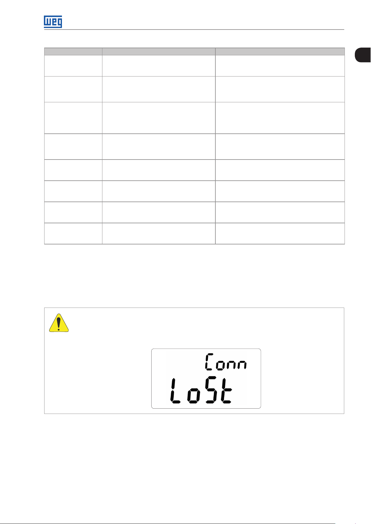
ATTENTION!
A bad contact in the HMI cable, or electric noise in the installation, can cause a failure in the
communication between the HMI and the control board. In such case, the operation through the HMI
becomes impossible and the HMI indicates the following message on the display:
CFW701 | 0-21
Page 30

Quick Parameter Reference, Faults and Alarms
0
0-22 | CFW701
Page 31

Safety Notices
1 SAFETY NOTICES
This Manual contains the information necessary for the correct use of the CFW701 Frequency Inverter.
It has been developed to be used by qualified personnel with suitable training or technical qualification for operating
this type of equipment.
1.1 SAFETY NOTICES IN THIS MANUAL
The following safety notices are used in this manual:
DANGER!
The procedures recommended in this warning have the purpose of protecting the user against dead,
serious injuries and considerable material damage.
DANGER!
Les procédures concernées par cet avertissement sont destinées à protéger l'utilisateur contre des
dangers mortels, des blessures et des détériorations matérielles importantes.
ATTENTION!
The procedures recommended in this warning have the purpose of avoiding material damage.
1
NOTE!
The information mentioned in this warning is important for the proper understanding and good
operation of the product.
1.2 SAFETY NOTICES ON THE PRODUCT
The following symbols are attached to the product, serving as safety notices:
High voltages are present.
Components sensitive to electrostatic discharge.
Do not touch them.
Mandatory connection to the protective ground (PE).
Connection of the shield to the ground.
Hot surface.
CFW701 | 1-1
Page 32

Safety Notices
1
1.3 PRELIMINARY RECOMMENDATIONS
DANGER!
Only qualified personnel familiar with the CFW701 Frequency Inverter and associated equipment
should plan or implement the installation, start-up and subsequent maintenance of this equipment.
These personnel must follow all the safety instructions included in this manual and/or defined by
local regulations.
Failure to comply with these instructions may result in life threatening and/or equipment damage.
DANGER!
Seulement personnes avec la qualification adéquate et familiarisation avec le CFW701 et équipements
associés doivent planifiquer ou implementer l'installation, mise en marche, operation et entretien de
cet équipement.
Cettes personnes doivent suivre toutes les instructions de sécurités indiquées dans ce manuel, et/
ou définies par normes locales.
L'inobservance des instructions de sécurité peut résulter en risque de vie et/ou dommages de cet
équipement.
NOTE!
For the purposes of this manual, qualified personnel are those trained to be able to:
1. Install, ground, energize and operate the CFW701 according to this manual and the effective legal
safety procedures.
2. Use protection equipment according to the established standards.
3. Give first aid services.
DANGER!
Always disconnect the input power before touching any electrical component associated to the inverter.
Many components can remain charged with high voltages or remain in movement (fans) even after
that AC power is disconnected or switched off.
Wait at least 10 minutes to assure a total discharge of the capacitors.
Always connect the equipment frame to the protection earth (PE) at the suitable connection point.
DANGER!
Débranchez toujours l'alimentation principale avant d'entrer en contact avec un appareil électrique
associé au variateur. Plusieurs composants peuvent rester chargés à un potentiel électrique élevé
et/ou être en mouvement (ventilateurs), même après la déconnexion ou la coupure de l'alimentation
en courant alternatif.
Attendez au moins 10 minutes que les condensateurs se déchargent complètement.
Raccordez toujours la masse de l'appareil à une terre protectrice (PE).
ATTENTION!
Electronic boards have components sensitive to electrostatic discharges. Do not touch directly
on components or connectors. If necessary, touch the grounded metallic frame before or use an
adequate grounded wrist strap.
1-2 | CFW701
Do not perform any high pot tests with the inverter!
If it is necessary consult WEG.
Page 33

Safety Notices
NOTE!
Frequency inverter may interfere with other electronic equipment. In order to reduce these effects,
take the precautions recommended in the chapter 3 Installation and Connection, of the user's manual.
NOTE!
Read the user's manual completely before installing or operating the inverter.
1
CFW701 | 1-3
Page 34

Safety Notices
1
1-4 | CFW701
Page 35

2 GENERAL INFORMATION
2.1 ABOUT THIS MANUAL
General Information
This manual presents the necessary information for the configuration of all of the functions and parameters of the
CFW701 Frequency Inverter. This manual must be used together with the CFW701 user's manual.
The text intents to supply additional information to facilitate the use and programming of the CFW701 in specific
applications.
2.2 TERMINOLOGY AND DEFINITIONS
2.2.1 Terms and Definitions Used in the Manual
Normal Duty Cycle (ND): it is the inverter operation regimen that defines the maximum current value for continuous
operation I
(Normal Duty – ND). It must be used for driving motors that are not subject in that application to high torques in
relation to their rated torque, when operating in permanent regimen, during start, acceleration or deceleration.
I
: inverter rated current for use with normal overload regimen (ND = Normal Duty).
nom-ND
Overload: 1.1 x I
Heavy Duty Cycle (HD): it is the inverter operation regimen that defines the maximum current value for continuous
operation I
(Heavy Duty (HD)). It must be used for driving motors that are subject in that application to high overload torques
in relation to their rated torque, when operating in constant speed, during start, acceleration or deceleration.
I
: inverter rated current for use with heavy overload regimen (HD = Heavy Duty).
nom-HD
Overload: 1.5 x I
and overload of 110 % during 1 minute. It is selected by programming P0298 (Application) = 0
nom-ND
/ 1 minute.
nom-ND
and overload of 150 % during 1 minute. It is selected by programming P0298 (Application) = 1
nom-HD
/ 1 minute.
nom-HD
2
Rectifier: the input circuit of the inverters that converts the input AC voltage into DC. It is formed by power diodes.
Pre-charge Circuit: it charges the DC Link capacitors with a limited current, thus avoiding current peaks when
powering the inverter.
DC Link: this is the inverter intermediate circuit, with DC voltage and current, obtained from the rectification of
the AC supply voltage, or from an external source; it supplies the output IGBTs inverter bridge.
U, V and W Arm: it is a set of two IGBTs of the phases U, V and W at the inverter output.
IGBT: “Insulated Gate Bipolar Transistor”; It is the basic component of the output inverter bridge. It operates like
an electronic switch in the saturated (closed switch) and cut (open switch) modes.
Braking IGBT: operates as a switch for the connection of the braking resistor. It is commanded by the DC Link level.
PTC: it’s a resistor whose resistance value in ohms increases proportionally to the increase of the temperature;
it is used as a temperature sensor in motors.
NTC: it’s a resistor whose resistance value in ohms decreases proportionally to the temperature increase; it is
used as a temperature sensor in power modules.
Keypad (HMI): Human-Machine Interface; It is the device that allows the control of the motor, the visualization
and the modification of the inverter parameters. It presents keys for commanding the motor, navigation keys and
a graphic LCD display.
MMF (Flash Memory Module): it is the nonvolatile memory that can be electrically written and erased.
RAM Memory: Random Access Memory (volatile).
PE: “P r otec ti v e Ea rth”.
CFW701 | 2-1
Page 36

General Information
RFI Filter: “Radio Frequency Interference Filter”. It is a filter that avoids interference in the radiofrequency range.
PWM: “Pulse Width Modulation”. It is a pulsing voltage that supplies the motor.
Switching Frequency: it is the inverter bridge IGBTs commutation frequency, specified normally in kHz.
2
General Enable: when activated, it accelerates the motor with the acceleration ramp provided Run/Stop = Run.
When deactivated, the PWM pulses are immediately blocked. It can be commanded through digital input programmed
for that function or via serial.
Run/Stop: inverter function that when activated (Run) accelerates the motor with the acceleration ramp until
reaching the speed reference, and when deactivated (Stop) decelerates the motor with the deceleration ramp
down to stop. It can be commanded through digital input programmed for that function or via serial. The HMI
keys and work in a similar manner:
= Run, = Stop.
Heatsink: it is a metal part designed for dissipating the heat generated by the power semiconductors.
Amp, A: ampères.
°C: degrees celsius.
°F: fahrenheit degree.
AC: alternating current.
DC: direct current.
CFM: “Cubic feet per minute”; it is a flow measurement unit.
hp: “Horse Power” = 746 Watts (power measurement unit, normally used to indicate the mechanical power of
electric motors).
Hz: hertz.
l/s: liters per second.
kg: kilogram = 1000 gram.
kHz: kilohertz = 1000 Hz.
mA: milliamp = 0.001 Amp.
min: minute.
ms: millisecond = 0.001 second.
Nm: Newton meter; torque measurement unit.
rms: “Root mean square”; effective value.
rpm: revolutions per minute: speed measurement unit.
s: second.
V: volts.
Ω: ohms.
2-2 | CFW701
Page 37

General Information
2.2.2 Numerical Representation
The decimal numbers are represented by means of digits without suffix. Hexadecimal numbers are represented
with the letter “h” after the number.
2.2.3 Symbols for the Parameter Properties Description
ro Reading only parameter.
cfg Parameter that can be changed only with a stopped motor.
V/f Parameter visible on the keypad (HMI) only in the V/f mode: P0202 = 0, 1 or 2.
Adj Parameter visible on the keypad (HMI) only in the V/f adjustable mode: P0202 = 2.
Vector Parameter visible on the keypad (HMI) only in the vector sensorless mode: P0202 = 4.
VVW Parameter visible on the keypad (HMI) only in the V VW mode: P0202 = 3.
Sless Parameter visible on the keypad (HMI) only in the vector sensorless mode: P0202 = 4.
2
CFW701 | 2-3
Page 38

General Information
2
2-4 | CFW701
Page 39

About the CFW701
3 ABOUT THE CFW701
The CFW701 is a high performance frequency inverter that makes it possible the control of speed and torque of
three-phase AC induction motors. The principal characteristic of this product is the “Vectrue” technology, which
presents the following advantages:
Scalar control (V/f), VV W or vector control programmable in the same product.
The “sensorless” vector control allows high torque and fast response, even at very slow speeds or during starting.
The “Optimal Braking” function for the vector control allows a controlled motor braking, eliminating in some
applications the braking resistor.
The vector control “Self-Tuning” function allows the automatic setting of the regulators and control parameters,
from the identification (also automatic) of the motor and load parameters.
3
CFW701 | 3-1
Page 40

About the CFW701
C3 RFI Filter (*)
DC+ DC-
BR
= DC bus connection
= Braking resistor
connection
R/L1/L
Mains power
supply
3
WPS software
WLP software
S/L2/N
T/L 3
Three-phase
rectifier
PE
PC
RS-485
Pre-
charge
RFI filter
DC link chokes
DC link capacitor bank
CFW701...DB... inver te rs)
Braking IGBT (available in
POWER
CONTROL
Control power supply and interfaces
between power and control
Inverter
with
IGBT
transistors
Feedback:
- voltage
- current
U/T1
V/T2
W/T3
PE
Motor
Keypad (remote)
Digital inputs
DI1 to DI8
Analog
inputs
AI1, AI2, AI3
PTC
protection
input
Keypad
CC701
Control
board with
a 32 bits
"RISC"
CPU
FLASH
Memory
Module
(Slot 5)
Accessories
COMM 1
(Slot 3 - Green)
= Keypad (HMI)
(*) The capacitor to the ground of the C3 RFI filter (it is possible to meet the
requirements of category C2 with this filter on mechanics A models) must be
disconnected for IT networks and grounded delta power supplies. Please
refer to item 3.2.3.1 Input Connections, of the CFW701 user's manual.
Figure 3.1: CFW701 block diagram
Analog outputs
AO1 and AO2
Relay
Digital outputs
DO1 (RL1) and
DO2 (RL2)
Transistor
Digital outputs
DO3 to DO5
3-2 | CFW701
Page 41

1
3
1 - Mounting supports
(for surface mounting)
2 - Back side of the inverter (outside for flange
mounting)
3 - Fan with fixing support
4 - Control accessory module (refer to section 7.2 -
Accessories, of the CFW701 user's manual)
5 - FLASH memory module (not included)
6 - Front cover frame sizes (sizes A, B and C)
7 - Keypad (HMI)
8 - Status LED (STATUS)
9 - CC700 control board
Figure 3.2: CFW701 main components
About the CFW701
2
9
5
4
6
7
3
8
Status LED
1
Green: Normal operation without fault or alarm
Yellow: In the alarm condition
Blinking red: In the fault condition
1
Figure 3.3: LEDs
CFW701 | 3-3
Page 42

About the CFW701
3
3-4 | CFW701
Page 43

Keypad (HMI)
4 KEYPAD (HMI)
The integral keypad can be used to operate and program (view / edit all parameters) of the CFW701 inverter. There
are two operation modes in the keypad: monitoring and programming. The key functions and display indications
of the keypad may change according to the operation mode. The programming mode consists of three levels.
- When in monitoring mode: press this key
to increase the speed.
- When in programming mode, level 1:
press this key to go back to the previous
group.
- When in programming mode, level 2:
press this key to go to the next parameter.
- When in programming mode, level 3: press
this key to increase the parameter value.
- When in programming mode, level 1:
press this key to go back to the monitoring
mode.
- When in programming mode, level 2:
press this key to go back to the level 1.
- When in programming mode, level 3:
press this key to cancel the new value
(the value will not be saved) and it will
return to level 2 of the programming
mode.
- Press this key to define the motor
rotation.
This option is active when:
P0223 = 2 or 3 in LOC and/or
P0226 = 2 or 3 in REM.
- Press this key to change between Local
and Remote mode.
This option is active when:
P0220 = 2 or 3.
USB communication port
- When in monitoring mode: press this key
to decrease the speed.
- When in programming mode, level 1:
press this key to go to the next group.
- When in programming mode, level 2:
press this key to go back to the previous
parameter.
- When in programming mode, level 3: press
this key to decrease the parameter value.
- When in monitoring mode: press this key
to enter in the programming mode.
- When in programming mode, level 1: press
this key to select the desired parameter
group – it shows the parameters of the
selected group.
- When in programming mode, level 2: press
this key to show the parameter – it shows
the parameter value for its modification.
- When in programming mode, level 3: press
this key to save the new parameter value – it
returns to level 2 of the programming mode.
- Press this key to accelerate the motor
according to the acceleration ramp time.
This option is active when:
P0224 = 0 in LOC and/or
P0227 = 0 in REM.
- Press this key to decelerate the motor
according to the deceleration ramp time.
This option is active when:
P0224 = 0 in LOC and/or
P0227 = 0 in REM.
4
- Press this key to accelerate the motor up to the speed set in P0122. The motor speed is
maintained while the key is pressed. When the key is released the motor decelerates up to its
complete stop.
This function is active when all the following conditions are met:
1. Start/Stop = Stop.
2. General Enable = Active.
3. P0225 = 1 in LOC and/or P0228 = 1 in REM.
Figure 4.1: HMI keys
CFW701 | 4-1
Page 44

Keypad (HMI)
4
4-2 | CFW701
Page 45

Programming Basic Instructions
5 PROGRAMMING BASIC INSTRUCTIONS
5.1 PARAMETERS STRUCTURE
In order to make the programming of the inverter easier, the parameters of the CFW701 were divided into 10
groups that can be individually selected in the Menu area of the keypad. When the ENTER/MENU key is pressed
on monitoring mode, the programming mode is set. In this mode, it is possible to select the desired group of
parameters through the keys and . Refer to the CFW701 user's manual for more details on the keypad keys
programming. The parameter group structure is presented in the next item.
NOTE!
The inverter leaves the factory with frequency (V/f 50/60 Hz mode) and voltage adjusted according
to the market.
The reset to the factory default may change the content of the parameters related to the frequency
(50 Hz / 60 Hz). In the detailed description, some parameters present values in parentheses, which
must be adjusted in the inverter for using the 50 Hz frequency.
5.2 GROUPS ACCESSED IN THE OPTION MENU IN THE MONITORING MODE
In the monitoring mode access the groups of the option “Menu” by pressing the ENTER/MENU “soft key”.
Table 5.1: Parameter groups accessed in the option menu of the monitoring mode
Group Contained Parameters or Groups
PAR A M All the parameters
READ Parameters used only for reading
MODIF Only parameters whose contents are different from the factory settings
BASIC
MOTOR Parameters related to the motor data control
I/O Groups related to digital and analog, inputs and outputs
NET Parameters related to the communication network
HMI Parameters for the keypad (HMI) configuration
HVAC Parameters related to the HVAC functions
STA R T U P Parameter for entering the “Oriented Start-up” mode
Parameters for simple applications: ramps, minimum and maximum speed, maximum current and torque boost.
Presented in details in the CFW701 user’s manual at item 5.2.2 Basic Application Menu.
5.3 PASSWORD SETTING IN P0000
P0000 – Access to Parameters
Adjustable
Range:
0 to 9999 Factory
Setting:
0
5
Properties:
Access Groups
via HMI:
In order to be able to change the content of the parameters, it is necessary to set correctly the password in P0000,
as indicated below. Otherwise the content of the parameters can only be visualized.
It is possible to customize the password by means of P0200. Refer to the description of this parameter in the
section 5.4 HMI on page 5-2, of this manual.
CFW701 | 5-1
Page 46

Programming Basic Instructions
Seq. Action/Result Display Indication
- Monitoring mode.
Press the ENTER/MENU key
1
to enter into the 1° level of the
programming mode.
- The PARAM group is already
2
available, press the ENTER/MENU
key to access parameter P00 00.
- Press ENTER/MENU key again to
3
access the parameter value.
- Press the or keys to set
4
the desired value.
- Press ENTER/MENU key when the
5
desired value is reached in order to
5
confirm the modification.
- Press the BACK/ESC key to go
6
back to the 2° level of programming
mode.
- Press the BACK/ESC key in order
7
to go back to the monitoring mode.
8 - Monitoring mode.
Figure 5.1: Sequence for allowing parameter changes via P0000
5.4 HMI
In the group “HMI” are the parameters related to the presentation of information on the keypad (HMI) display. See
next the detailed description of the possible settings for those parameters.
P0200 – Password
Adjustable
Range:
Properties:
Access Groups
via HMI:
5-2 | CFW701
0 = Inactive
1 = Active
2 = Change Password
HMI
Factory
Setting:
1
Page 47

Programming Basic Instructions
Description:
It allows changing the password and/or setting its status, configuring it as active or inactive. For more details
on each option, refer to the Table 5.2 on page 5-3 described next.
Table 5.2: Options for the parameter P0200
P0200 Kind of Action
0 (Inactive) It allows parameter changes regardless of P0000
1 (Active) It does only allow parameter changes when the content of P0000 is equal to the password
2 (Change Password) It makes the value presented in P0000 the current password
Follow the procedure below to change your password:
1. Enter the current password value (factory settings, P0000 = 5).
2. Set the password parameter to inactive (P0200 = 0).
3. Enter the new desired password value in P0000.
4. Set the password parameter to change password (P0200 = 2).
5. The setting is completed, the new password is active and P0200 is automatically set to 1 (Enables password).
P0205 – Main Display Parameter Selection
P0206 – Secondary Display Parameter Selection
Adjustable
Range:
Properties:
Access Groups
via HMI:
Description:
These parameters define which parameters are displayed on the keypad in the monitoring mode.
More details on the programming can be seen in section 5.6 DISPLAY INDICATIONS IN THE MONITORING
MODE SETTINGS on page 5-14.
0 to 1199 Factory
Setting:
HMI
P0205 = 2
P0206 = 3
P0208 – Main Display Scale Factor
P0211 – Secondary Display Scale Factor
5
Adjustable
Range:
0.1 to 1000.0 % Factory
Setting:
100.0 %
CFW701 | 5-3
Page 48

Programming Basic Instructions
P0210 – Main Display Decimal Point
P0212 – Secondary Display Decimal Point
Adjustable
Range:
Properties:
Access Groups
via HMI:
Description:
These parameters allow changing the range of the Main Display and the Secondary Display in order to convert
motor variables such as speed (rpm) in application units such as meters/minutes or cubic feet/minutes for example.
0 = wxyz
1 = wxy.z
2 = wx.yz
3 = w.xyz
4 = As P0511
5 = As P0513
6 = As P0515
7 = As P0512
HMI
Factory
Setting:
P0210 = 0
P0212 = 1
5
5-4 | CFW701
Page 49

P0209 – Main Display Engineering Unit
Programming Basic Instructions
Adjustable
Range:
Properties:
Access Groups
via HMI:
0 = None
1 = V
2 = A
3 = rpm
4 = s
5 = ms
6 = None
7 = m
8 = None
9 = None
10 = %
11 = °C
12 = None
13 = Hz
14 = None
15 = h
16 = W
17 = kW
18 = None
19 = None
20 = min
21 = °F
22 = bar
23 = mbar
24 = psi
25 = Pa
26 = kPa
27 = MPa
28 = mwc
29 = mca
30 = gal
31 = l
32 = in
33 = ft
34 = m³
35 = ft³
36 = gal/s
37 = gal/min
38 = gal/h
39 = l/s
40 = l/min
41 = l/h
42 = m/s
43 = m/min
44 = m/h
45 = ft/s
46 = ft/min
47 = ft/h
48 = m³/s
49 = m³/min
50 = m³/h
51 = ft³/s
52 = ft³/min
53 = ft³/h
54 = As per P0510
55 = As per P0512
56 = As per P0514
57 = As per P0516
HMI
Factory
Setting:
3
5
CFW701 | 5-5
Page 50

Programming Basic Instructions
Description:
This parameter selects the engineering unit to be presented in the main display. The content of this parameter
is automatically adjusted to match the unit of the parameter selected by P0205 when its value is changed by
the HMI.
P0216 – HMI Backlighting
Adjustable
Range:
Properties:
Access Groups
via HMI:
Description:
It allows setting the keypad (HMI) display contrast level. Higher values configure a higher contrast level.
0 to 15 Factory
Setting:
HMI
15
5.5 INDIRECT ENGINEERING UNITS
This parameter group allows the user to configure the indirect engineering units for SoftPLC user parameters.
5
5-6 | CFW701
Page 51

P0510 – Indirect Engineering Unit 1
Programming Basic Instructions
Adjustable
Range:
Properties:
Access Groups
via HMI:
0 = None
1 = V
2 = A
3 = rpm
4 = s
5 = ms
6 = None
7 = m
8 = None
9 = None
10 = %
11 = °C
12 = None
13 = Hz
14 = None
15 = h
16 = W
17 = kW
18 = None
19 = None
20 = min
21 = °F
22 = bar
23 = mbar
24 = psi
25 = Pa
26 = kPa
27 = MPa
28 = mwc (meter of water column)
29 = mca (metro de coluna d’agua)
30 = gal
31 = l (liter)
32 = in
33 = ft
34 = m³
35 = ft³
36 = gal/s
37 = gal/min (= GPM)
38 = gal/h
39 = l/s
40 = l/min
41 = l/h
42 = m/s
43 = m/min
44 = m/h
45 = ft/s
46 = ft/min
47 = ft/h
48 = m³/s
49 = m³/min
50 = m³/h
51 = ft³/s
52 = ft³/min
53 = ft³/h
HMI
Factor y
Setting:
22
5
CFW701 | 5-7
Page 52

Programming Basic Instructions
Description:
This parameter selects the engineering unit that will be displayed in SoftPLC user parameter that is associated
whit it, i.e., any SoftPLC user parameter that has its engineering unit associated with an indirect engineering unit
1 will be displayed in this format in the CFW701 HMI.
NOTE!
The parameters P1011, P1015, P1027, P1028, P1031 and P1033 of the Main PID controller (HVAC
functions) are associated with the indirect engineering unit 1.
P0511 – Indirect Decimal Point 1
Adjustable
Range:
Properties:
Access Groups
via HMI:
5
Description:
This parameter selects the decimal point that will be displayed in SoftPLC user parameter that is associated
whit it, i.e., any SoftPLC user parameter that has its decimal point associated with an indirect decimal point 1
will be displayed in this format in the CFW701 HMI.
NOTE!
The parameters P1011, P1015, P1027, P1028, P1031 and P1033 of the Main PID controller (HVAC
functions) are associated with the indirect decimal point 1.
0 = wxyz
1 = wxy.z
2 = wx.yz
3 = w.xyz
HMI
Factor y
Setting:
1
5-8 | CFW701
Page 53

P0512 – Indirect Engineering Unit 2
Programming Basic Instructions
Adjustable
Range:
Properties:
Access Groups
via HMI:
0 = None
1 = V
2 = A
3 = rpm
4 = s
5 = ms
6 = None
7 = m
8 = None
9 = None
10 = %
11 = °C
12 = None
13 = Hz
14 = None
15 = h
16 = W
17 = kW
18 = None
19 = None
20 = min
21 = °F
22 = bar
23 = mbar
24 = psi
25 = Pa
26 = kPa
27 = MPa
28 = mwc (meter of water column)
29 = mca (metro de coluna d’agua)
30 = gal
31 = l (liter)
32 = in
33 = ft
34 = m³
35 = ft³
36 = gal/s
37 = gal/min (= GPM)
38 = gal/h
39 = l/s
40 = l/min
41 = l/h
42 = m/s
43 = m/min
44 = m/h
45 = ft/s
46 = ft/min
47 = ft/h
48 = m³/s
49 = m³/min
50 = m³/h
51 = ft³/s
52 = ft³/min
53 = ft³/h
HMI
Factory
Setting:
11
5
CFW701 | 5-9
Page 54

Programming Basic Instructions
Description:
This parameter selects the engineering unit that will be displayed in SoftPLC user parameter that is associated
whit it, i.e., any SoftPLC user parameter that has its engineering unit associated with an indirect engineering unit
2 will be displayed in this format in the CFW701 HMI.
NOTE!
The parameters P1060, P1062, P1073, P1074, P1076 and P1078 of the External PID controller 1
(HVAC functions) are associated with the indirect engineering unit 2.
P0513 – Indirect Decimal Point 2
Adjustable
Range:
Properties:
Access Groups
via HMI:
5
Description:
This parameter selects the decimal point that will be displayed in SoftPLC user parameter that is associated
whit it, i.e., any SoftPLC user parameter that has its decimal point associated with an indirect decimal point 2
will be displayed in this format in the CFW701 HMI.
NOTE!
The parameters P1060, P1062, P1073, P1074, P1076 and P1078 of the External PID controller 1
(HVAC functions) are associated with the indirect decimal point 2.
0 = wxyz
1 = wxy.z
2 = wx.yz
3 = w.xyz
HMI
Factory
Setting:
1
5-10 | CFW701
Page 55

P0514 – Indirect Engineering Unit 3
Programming Basic Instructions
Adjustable
Range:
Properties:
Access Groups
via HMI:
0 = None
1 = V
2 = A
3 = rpm
4 = s
5 = ms
6 = None
7 = m
8 = None
9 = None
10 = %
11 = °C
12 = None
13 = Hz
14 = None
15 = h
16 = W
17 = kW
18 = None
19 = None
20 = min
21 = °F
22 = bar
23 = mbar
24 = psi
25 = Pa
26 = kPa
27 = MPa
28 = mwc (meter of water column)
29 = mca (metro de coluna d’agua)
30 = gal
31 = l (liter)
32 = in
33 = ft
34 = m³
35 = ft³
36 = gal/s
37 = gal/min (= GPM)
38 = gal/h
39 = l/s
40 = l/min
41 = l/h
42 = m/s
43 = m/min
44 = m/h
45 = ft/s
46 = ft/min
47 = ft/h
48 = m³/s
49 = m³/min
50 = m³/h
51 = ft³/s
52 = ft³/min
53 = ft³/h
HMI
Factory
Setting:
10
5
CFW701 | 5-11
Page 56

Programming Basic Instructions
Description:
This parameter selects the engineering unit that will be displayed in SoftPLC user parameter that is associated
whit it, i.e., any SoftPLC user parameter that has its engineering unit associated with an indirect engineering unit
3 will be displayed in this format in the CFW701 HMI.
NOTE!
The parameters P1080, P1082, P1093, P1094, P1096 and P1098 of the External PID controller 2
(HVAC functions) are associated with the indirect engineering unit 3.
P0515 – Indirect Decimal Point 3
Adjustable
Range:
Properties:
Access Groups
via HMI:
5
Description:
This parameter selects the decimal point that will be displayed in SoftPLC user parameter that is associated
whit it, i.e., any SoftPLC user parameter that has its decimal point associated with an indirect decimal point 3
will be displayed in this format in the CFW701 HMI.
NOTE!
The parameters P1080, P1082, P1093, P1094, P1096 and P1098 of the External PID controller 2
(HVAC functions) are associated with the indirect decimal point 3.
0 = wxyz
1 = wxy.z
2 = wx.yz
3 = w.xyz
HMI
Factory
Setting:
1
5-12 | CFW701
Page 57

P0516 – Indirect Engineering Unit 4
Programming Basic Instructions
Adjustable
Range:
Properties:
Access Groups
via HMI:
0 = None
1 = V
2 = A
3 = rpm
4 = s
5 = ms
6 = None
7 = m
8 = None
9 = None
10 = %
11 = °C
12 = None
13 = Hz
14 = None
15 = h
16 = W
17 = kW
18 = None
19 = None
20 = min
21 = °F
22 = bar
23 = mbar
24 = psi
25 = Pa
26 = kPa
27 = MPa
28 = mwc (meter of water column)
29 = mca (metro de coluna d’agua)
30 = gal
31 = l (liter)
32 = in
33 = ft
34 = m³
35 = ft³
36 = gal/s
37 = gal/min (= GPM)
38 = gal/h
39 = l/s
40 = l/min
41 = l/h
42 = m/s
43 = m/min
44 = m/h
45 = ft/s
46 = ft/min
47 = ft/h
48 = m³/s
49 = m³/min
50 = m³/h
51 = ft³/s
52 = ft³/min
53 = ft³/h
HMI
Factory
Setting:
13
5
CFW701 | 5-13
Page 58

Programming Basic Instructions
Description:
This parameter selects the engineering unit that will be displayed in SoftPLC user parameter that is associated
whit it, i.e., any SoftPLC user parameter that has its engineering unit associated with an indirect engineering unit
4 will be displayed in this format in the CFW701 HMI.
NOTE!
The parameters P1036, P1043 and P1047 are related to speed limits (Hz or rpm) on HVAC functions
and are associated with the indirect engineering unit 4.
P0517 – Indirect Decimal Point 4
Adjustable
Range:
0 = wxyz
1 = wxy.z
Factory
Setting:
1
2 = wx.yz
3 = w.xyz
Properties:
Access Groups
HMI
via HMI:
5
Description:
This parameter selects the decimal point that will be displayed in SoftPLC user parameter that is associated
whit it, i.e., any SoftPLC user parameter that has its decimal point associated with an indirect decimal point 4
will be displayed in this format in the CFW701 HMI.
NOTE!
The parameters P1036, P1043 and P1047 are related to speed limits (Hz or rpm) on HVAC functions
and are associated with the indirect decimal point 4.
5.6 DISPLAY INDICATIONS IN THE MONITORING MODE SETTINGS
Every time the inverter is powered the display goes to the Monitoring Mode. To facilitate reading the parameters
of the inverter, the display is designed to show two parameters at the same time according to the user's choice.
These parameters (Main Display and Secondary Display) are shown in numerical form. The selection of these
parameters is done via P0205 and P0206, as shown in Figure 5.2 on page 5-14.
Inverter status
Menu selection of parameter
groups
Figure 5.2: Screen at startup and display indication
Secondary display (selected by P0206).
Displays the content of parameter (Pxxxx),
value of parameter (Pxxxx), fault indication
(Fxxx) or alarm (Axxx)
Engineering unit of the main display
(selected by P0209)
Main display (selected by P0205).
Displays the content of parameter (Pxxxx),
value of parameter (Pxxxx), Fault indication
(Fxxx) or Alarm (Axxx)
5.7 INCOMPATIBILITY BETWEEN PARAMETERS
If any of the combinations listed below occur, the CFW701 goes to the “Config” state.
1. Two or more DIx (P0263...P0270) programmed for (8 = FWD/REV).
2. Two or more DIx (P0263 .... P0270) programmed for (9 = LOC/REM).
5-14 | CFW701
Page 59

Programming Basic Instructions
3. Two or more DIx (P0263 .... P0270) programmed for (14 = Ramp 2).
4. Two or more DIx (P0263 .... P0270) programmed for (15 = Speed/Torque).
5. Two or more DIx (P0263 .... P0270) programmed for (24 = Disable Flying Start).
6. Two or more DIx (P0263 .... P0270) programmed for (25 = DC Link Regulator).
7. Two or more DIx (P0263 .... P0270) programmed for (26 = Programming Off).
8. Two or more DIx (P0263 .... P0270) programmed for (27 = Load User 1).
9. Two or more DIx (P0263 .... P0270) programmed for (28 = Load User 2).
10. Two or more DIx (P0263...P0270) programmed for (23 = Bypass mode).
11. Two or more DIx (P0263...P0270) programmed for (24 = Five mode).
12. Two or more DOx (P0275 ...P0279) programed for (39 = Drive Bypass Contactor).
13. Two or more DOx (P0275 ...P0279) programed for (40 = Mains Bypass Contactor).
14. [P0583 ≠ 0] and [P0029.bit9 = 1] (with Safety Stop) OR no DIx (P0263...P0270) programmed for (23 = Bypass
mode) OR no DOx (P0275 ...P0279) programed for (39 = Drive Bypass Contactor) OR no DOx (P0275 ...P0279)
programed for (40 = Mains Bypass Contactor).
15. [P0583 = 0] and OR any DIx (P0263...P0270) programmed for (23 = Bypass mode) OR any DOx (P0275 ...P0279)
programed for (39 = Drive Bypass Contactor) OR any DOx (P0275 ...P0279) programed for (40 = Mains Bypass
Contactor).
16. [P0580 ≠ 0] AND [P0029.bit9 = 1] (with Safety Stop).
17. [P0202 programmed for (0 = V/f 60 Hz) OR (1 = V/f 50 Hz) OR (2 = Adjustable V/f) OR (3 = VVW)] AND
[P0231 = 1 (No Ramp Ref.) OR P0231 = 2 (Max.Torque Cur) OR P0236 = 1 (No Ramp Ref.) OR P0236 = 2
(Max.Torque Cur) OR P0241 = 1 (No Ramp Ref.) OR P0241 = 2 (Max.Torque Cur).
18. [P0202 programmed for (0 = V/f 60 Hz) OR (1 = V/f 50 Hz) OR (2 = Adjustable V/f) OR (3 = V VW )] AND [DIx (P0263...
P0270) programmed for (10 = JOG+) OR (11 = JOG-).
19. [P0224 programmed for (1 = DIx) OR P0227 programmed for (1 = DIx)] AND [without DIx (P0263...P0270)
programmed for (1 = Run/Stop) AND without DIx (P0263...P0270) programmed for (2 = General Enable) AND
without DIx (P0263...P0270) programmed for (3 = Fast Stop).
5
20. P0202 programed for 4 (Sensorless) and P0297 = 0 (1.25 kHz).
21. [31 ≤ P0295 ≤ 40] and [P0297 > 2].
22. [40 ≤ P0295 ≤ 46] and [P0297 ≠ 0 OR P0297 ≠ 4].
CFW701 | 5-15
Page 60

Programming Basic Instructions
5
5-16 | CFW701
Page 61

Inverter Model and Accessories Identification
6 INVERTER MODEL AND ACCESSORIES IDENTIFICATION
In order to identify the model of the inverter, verify the code existent on the product identification labels: the
complete one, located at the side of the inverter, or the abbreviated one, under the keypad (HMI). The figures
below show examples of those labels.
Manufacturing date
CFW701 model
WEG part number
Inverter net weight
Input rated data (voltage, number of phases,
rated currents for operation with ND and HD
overload cycles, and frequency)
Current specifications for operation with
normal overload cycle (ND)
Current specifications for operation with
heavy overload cycle (HD)
(a) Nameplate af fixed to the side of the inverter
(47 corresponds to
week and H to year)
Serial number
Maximum environment
temperature
Output rated data (voltage,
number of phases, rated
currents for operation with
ND and HD overload cycles,
overload currents for 1 min
and 3 s, and frequency range)
The maximum output
frequency depends on the
settings of the motor rated
frequency, control mode and
inverter switching frequency.
For further details, see
CFW701 user's manual table
8.1.
Part number
Serial number
(b) Nameplate located under the keypad
Figure 6.1: (a) and (b) Nameplates
CFW701 model
Manufacturing date
(47 corresponds to
week and H to year)
Once the inverter model identification code is verified, one must interpret it in order to understand its meaning.
Refer to the section 2.3 Identification, of the CFW701 user's manual.
6.1 INVERTER DATA
In this group are the parameters related to the inverter information and characteristics, such as inverter model,
accessories identified by the control circuit, software version, switching frequency, etc.
P0023 – Software Version
Adjustable
Range:
Properties: ro
Access Groups
via HMI:
0.00 to 655.35 Factory
Setting:
READ
6
Description:
It indicates the software version contained in the FLASH memory of the microcontroller located on the control
board.
CFW701 | 6-1
Page 62

Inverter Model and Accessories Identification
P0028 – Accessories Configuration
Adjustable
Range:
0000h to FFFFh Factory
Setting:
Properties: ro
Access Groups
READ
via HMI:
Description:
Those parameters identify by means of a hexadecimal code the accessories that were found installed on the
control module.
The next table shows the codes shown in those parameters, regarding the main CFW701 accessories.
Table 6.1: CFW701 accessory identification codes
Name Description
RS-485-01 RS-485 serial communication module CE--
MMF-02 FLASH memory module ----
Identification Code
P0028
(1)
For the FLASH memory module, the P0028 identification code will depend on the combination of these
accessories, as presented in the next table.
Tabl e 6 . 2 : Formation of the two first codes for P0028 parameter
6
(1)
Bit 6: indicates the presence of the FLASH memory module (0 = without memory module, 1 = with memory
7 6 5 4 3 2 1 0
∅
Module
FLASH Memory
2nd Hexadecimal Code 1st Hexadecimal Code
Bits
∅
0 0 0 0
module).
P0029 – Power Hardware Configuration
Adjustable
Range:
Properties: ro
Access Groups
via HMI:
Bit 0 to 5 = Rated Current
Bit 6 and 7 = Rated Voltage
Bit 8 = RFI Filter
Bit 9 = Safety Relay
Bit 10 = (0)24 V/(1)DC Link
Bit 11 = Always 0
Bit 12 = Dyn. Brak. IGBT
Bit 13 = Special
Bit 14 and 15 = Reserved
READ
Factory
Setting:
6-2 | CFW701
Page 63
Inverter Model and Accessories Identification
Description:
In a similar way than parameters P0028, the parameter P0029 identifies the inverter model and the present
accessories.
The codification is formed by the combination of binary digits, and presented in the keypad (HMI) in hexadecimal
format.
The bits that compose the code are explained in the next table.
Tabl e 6 . 3 : Parameter P0029 code constitution
Bits
15 14 13 12 11 10 9 8 7 6 5 4 3 2 1 0
Voltage
00 = 200…240 V
1 1 0
4th Hexadecimal Code 3rd Hexadecimal Code 2nd Hexadecimal Code 1st Hexadecimal Code
0
with braking IGBT
with 24 V supply
1
01 = 380…480 V
10 = 500...600 V
with safety relay
Current
Bits 15, 14 and 13: are fixed in 110.
Bit 12: it indicates the presence of the dynamic braking IGBT (0 = with braking IGBT, 1 = without braking IGBT).
Note:
Frame size D/500 / 600 V models are not able to identify the absence of the dynamic braking IGBT, always
indicate "0 = with braking IGBT", even if the dynamic braking IGBT is absent. See intelligent code on the
product label to identify the presence or absence of the dynamic braking IGBT.
Bit 11: always 0.
Bit 10: indicates if the inverter has the DC/DC converter for receiving external 24 V electronics power supply
(0 = with DC/DC converter, 1 = without DC/DC 24 V converter).
Bit 9: indicates the presence of the safety relay (0 = without safety relay, 1 = with safety relay).
Bit 8: indicates if the inverter is equipped with RFI suppressor filter (0 = without RFI filter, 1 = with RFI filter).
Note:
Frame size B/500 / 600 V models are not able to identify the presence of the Suppressor RFI Filter, always
indicate "0 = without RFI Filter ", even if the Suppressor RFI Filter is present. See intelligent code on the
product label to identify the presence or absence of the Suppressor RFI Filter.
Bits 7 and 6: indicate the inverter power supply voltage (00 = 200...240 V, 01 = 380…480 V, 10 = 500...600 V).
Bits 5, 4, 3, 2, 1 and 0: together with the voltage indication bits (7 and 6), they indicate the inverter rated current
(ND). The next table presents the combinations available for those bits.
6
CFW701 | 6-3
Page 64

Inverter Model and Accessories Identification
Tabl e 6 . 4: Current codification for the parameter P0029
2nd
Frame Size Voltage Current
2 A * 0 0
6 A * 0 1
7 A * 0 2
10 A * 0 3
A
B
C
D
E
A
B
200...240 V
6
C
D
E
B
C
D
E
* Models with single-phase/three-phase power supply.
** Models with 24 V fan power supply.
380...480 V
500...600 V
7 A 0 4
10 A 0 5
13 A 0 6
16 A 0 7
24 A 0 8
28 A 0 9
33.5 A 0 A
45 A 0 C
54 A 0 D
70 A 0 E
86 A 1 0
105 A 1 1
180 A 1 2
211 A 1 3
142 A 1 4
3.6 A 4 0
5 A 4 1
7 A 4 2
10 A 4 4
13.5 A 4 5
17 A 4 8
24 A 4 6
31 A 4 7
38 A 4 3
45 A 4 A
58.5 A 4 B
70.5 A 4 C
88 A 4 D
105 A 5 0
142 A 5 1
180 A 5 2
211 A 5 3
2.9 A 8 A
4.2 A 8 B
7 A 8 C
10 A 8 D
12 A 8 E
17 A 8 F
22 A 8 6
27 A 8 7
32 A 8 8
44 A 8 9
22 A 8 6
27 A 8 7
32 A 8 8
44 A 8 9
53 A 9 0
63 A 9 1
80 A 9 2
107 A 9 3
125 A 9 4
150 A 9 5
53 A** B 1
63 A* * B 2
80 A* * B 3
Hexadecimal
Code
1st
Hexadecimal
Code
6-4 | CFW701
Page 65

Inverter Model and Accessories Identification
Example: For a 10 A, 380...480 V CFW701, with RFI suppressor filter, without safety relay and without external
24 V supply, the hexadecimal code presented in the keypad (HMI) for the parameter P0029 is C544 (refer to the
Table 6.5 on page 6-5).
Table 6.5: Example of the code at P0029 for a specific inverter model
15 14 13 12 11 10 9 8 7 6 5 4 3 2 1 0
1 1 0 0 0 1 0 1 0 1 0 0 0 1 0 0
C 5 4 4
6
CFW701 | 6-5
Page 66

Inverter Model and Accessories Identification
P0295 – ND/HD VFD Rated Current
Adjustable
Range:
6
Properties: ro
Access Groups
via HMI:
0 = 2 A / 2 A
1 = 3.6 A / 3.6 A
2 = 5 A / 5 A
3 = 6 A / 5 A
4 = 7 A / 5.5 A
5 = 7 A / 7 A
6 = 10 A / 8 A
7 = 10 A / 10 A
8 = 13 A / 11 A
9 = 13.5 A / 11 A
10 = 16 A / 13 A
11 = 17 A / 13.5 A
12 = 24 A / 19 A
13 = 24 A / 20 A
14 = 28 A / 24 A
15 = 31 A / 25 A
16 = 33.5 A / 28 A
17 = 38 A / 33 A
18 = 45 A / 36 A
19 = 45 A / 38 A
20 = 54 A / 45 A
21 = 58.5 A / 47 A
22 = 70 A / 56 A
23 = 70.5 A / 61 A
24 = 86 A / 70 A
25 = 88 A / 73 A
26 = 105 A / 86 A
27 = 105 A / 88 A
28 = 142 A / 115 A
29 = 180 A / 142 A
30 = 211 A / 180 A
31 = 2.9 A / 2.7 A
32 = 4.2 A / 3.8 A
33 = 7 A / 6.5 A
34 = 10 A / 9 A
35 = 12 A / 10 A
36 = 17 A / 17 A
37 = 22 A / 19 A
38 = 27 A / 22 A
39 = 32 A / 27 A
40 = 44 A / 36 A
41 = 53 A / 44 A
42 = 63 A / 53 A
43 = 80 A / 66 A
44 = 107 A / 90 A
45 = 125 A / 107 A
46 = 150 A / 122 A
READ
Factory
Setting:
Description:
This parameter presents the inverter rated current for the normal overload regimen (ND) and for the heavy
overload regimen (HD). The inverter operation mode, if it is ND or HD, is defined by the content of P0298.
6-6 | CFW701
Page 67

P0296 – Line Rated Voltage
Inverter Model and Accessories Identification
Adjustable
Range:
0 = 200 / 240 V
1 = 380 V
2 = 400 / 415 V
Factory
Setting:
According to
the inverter
model
3 = 440 / 460 V
4 = 480 V
5 = 500 / 525 V
6 = 550 / 575 V
7 = 600 V
Properties: cfg
Access Groups
via HMI:
Description:
Setting according to the inverter power supply voltage.
The adjustable range depends on the inverter model, according to the Table 6.6 on page 6-7, which also
presents the factory default value.
NOTE!
When adjusted via the keypad (HMI), this parameter may change automatically the following
parameters: P0151, P0153, P0185, P0321, P0322 and P0323.
Table 6.6: P0296 setting according to the CFW701 inverter model
Inverter Model Adjustable Range Factory Setting
200-240 V 0 = 200 ... 240 V 0
380-480 V
500-600V
P0297 – Switching Frequency
Adjustable
Range:
Properties: cfg
Access Groups
via HMI:
0 = 1.25 kHz
1 = 2.5 kHz
2 = 5.0 kHz
3 = 10.0 kHz
4 = 2.0 kHz
1 = 380 V
2 = 400 / 415 V
3 = 440 / 460 V
4 = 480 V
5 = 500 / 525 V
6 = 550 / 575 V
7 = 600 V
6
3
6
Factory
Setting:
According to
the inverter
model
Description:
Refer to the allowed current for switching frequencies different from the default, in the tables available in chapter
8 Technical Specifications, of the CFW701 user's manual.
The inverter switching frequency can be adjusted according to the needs of the application. Higher switching
frequencies imply in lower motor acoustic noise, however, the selection of the switching frequency results in a
compromise between the motor acoustic noises, the losses in the inverter IGBTs and the maximum allowed
currents.
CFW701 | 6-7
Page 68

Inverter Model and Accessories Identification
The reduction of the switching frequency reduces effects related to motor instability, which occur in specific
application conditions. It also reduces the earth leakage current, being able to avoid the actuation of the faults
F0074 (Ground Fault) or F0070 (Output Overcurrent/Short-circuit).
Note: The option 0 (1.25 kHz) is only allowed for the V/f or VV W control (P0202 = 0, 1, 2 or 3).
P0298 – Application
Adjustable
Range:
0 = Normal Duty (ND)
1 = Heavy Duty (HD)
Factory
Setting:
0
Properties: cfg
Access Groups
via HMI:
Description:
Set the content of this parameter according to the application.
The Normal Duty Regimen (ND) defines the maximum current for continuous operation (I
nom-ND
) and an
overload of 110 % during 1 minute. It must be used for driving motors that are not subject in that application
to high torques in relation to their rated torque, when operating in permanent regimen, during start, acceleration
or deceleration.
The Heavy Duty Regimen (HD) defines the maximum current for continuous operation (I
nom-HD
) and an
overload of 150 % during 1 minute. It must be used for driving motors that are subject in that application
to high overload torques in relation to their rated torque, when operating in constant speed, during start,
acceleration or deceleration.
6
The I
Specifications, for more details regarding these operation regimens.
nom-ND
and I
are presented in P0295. Refer to the CFW701 user's manual chapter 8 Technical
nom-HD
6-8 | CFW701
Page 69

Starting-up and Settings
7 STARTING-UP AND SETTINGS
In order to start-up in the several types of controls, beginning from the factory settings, consult the following
sections:
section 9.5 START-UP IN THE V/f CONTROL MODE on page 9-11.
section 10.3 VVW CONTROL MODE START-UP on page 10-4.
section 11.9 START-UP IN THE VECTOR MODES SENSORLESS on page 11-24.
In order to use previously loaded parameters, refer to the section 7.1 BACKUP PARAMETERS on page 7-1,
described next.
7.1 BACKUP PARAMETERS
The CFW701 BACKUP functions allow saving the content of the current inverter parameters in a specific memory,
or vice-versa (overwrite the contents of the current parameters with the memory contents). Besides, there is a
function exclusive for software update, by means of the FLASH Memory Module.
P0204 – Load/Save Parameters
Adjustable
Range:
Properties: cfg
Access Groups
via HMI:
Description:
It makes it possible to save the actual inverter parameters in an area of the control module memory or the other
way around, to load the contents of that area into the parameters. It also allows resetting the Time Enabled
(P0043), kWh (P0044) and Fan Enabled Time (P0045) counters. The Table 7.1 on page 7-1 describes the
actions performed by each option.
0 = Not Used
1 = Not Used
2 = Reset P0045
3 = Reset P0043
4 = Reset P0044
5 = Load WEG 60 Hz
6 = Load WEG 50 Hz
7 = Load User 1
8 = Load User 2
9 = Save User 1
10 = Save User 2
Factory
Setting:
0
7
Table 7.1: Parameter P0204 options
P0204 Action
0, 1 Not Used: no action
2 Reset P0045: resets the enabled fan hour counter
3 Reset P0043: resets the enabled hours counter
4 Reset P0044: resets the kWh counter
5 Load WEG 6 0 Hz: loads the 60 Hz factory settings into the inver ter parameters
6 Load WEG 50 Hz: loads the 50 Hz factory settings into the inverter parameters
7 Load User 1: loads the User 1 parameters into the current inverter parameters
8 Load User 2: loads the User 2 parameters into the current inverter parameters
9 Save User 1: saves the current inverter parameters into the User 1 parameter memory
10 Save User 2: saves the current inverter parameters into the User 2 parameter memory
CFW701 | 7-1
Page 70

Starting-up and Settings
P0204 = 09
User
memory 1
P0204 = 7
Current
inverter
parameters
Figure 7.1: Parameter transfer
P0204 = 5
P0204 = 10
P0204 = 8
ou 6
Factory
setting
User
memory 2
In order to load parameters from user 1 and/or User 2 to the CFW701 operation area (P0204 = 7 or 8), it is
necessary that these areas had been saved previously.
The operation of loading one of those memories can also be performed via digital inputs (DIx). Refer to item
13.1.3 Digital Inputs on page 13-9, for more details regarding this programming (P0204 = 9 or 10).
NOTE!
When P0204 = 5 or 6, the parameters P0296 (Rated voltage), P0297 (Switching frequency), P0308
(Serial address) are not changed by the factory settings.
P0317 – Oriented Start-up
Adjustable
Range:
0 = No
1 = Yes
Factory
Setting:
0
Properties: cfg
7
via HMI:
Access Groups
STA RTU P
Description:
When this parameter is changed to “1”, the Oriented Start-up routine starts. The CFW701 goes into the “CONF”
state, which is indicated on the HMI. Within the Oriented Start-up, the user has access to the important
configuration parameters of the CFW701 and of the motor for the control type to be used in the application. For
further information on the use of this parameter, refer to the following sections:
section 10.3 VVW CONTROL MODE START-UP on page 10-4.
section 11.9 START-UP IN THE VECTOR MODES SENSORLESS on page 11-24.
P0318 – Copy Function MMF
Adjustable
Range:
Properties: cfg
Access Groups
via HMI:
0 = Off
1 = VFD → MMF
2 = MMF → VFD
3 = VFD Synchronization → MMF
4 = MMF Format
5 = SoftPLC Program Copy
6 = SoftPLC Program Save
Factory
Setting:
0
7-2 | CFW701
Page 71

Starting-up and Settings
Description:
This function allows saving the contents of the inverter writing parameters in the FLASH Memory Module
(MMF), or vice-versa, and can be used to transfer the contents of the parameters from one inverter to another.
P0318 Action
0 Inactive: no action
1 Inverter → MMF: transfers the inverter current parameters contents to the MMF
2 MMF → Inverter: transfers the contents of the parameters stored in the MMF to the inverter control board
3 Updates the MMF automatically whenever any parameter of the CFW701 is changed
4 Format the MMF
5 Copy the SoftPLC program from the MMF to the CFW701
6 Save the SoftPLC program of the CFW701 to the MMF
After storing the parameters of one inverter in a FLASH memory module, it is possible to pass them to another
inverter with this function.
NOTE!
During the inverter operation, the modified parameters are saved in the FLASH memory module
regardless of user's command, when P0318 = 3. This assures that the MMF will always have an
updated copy of the inverter parameters.
Table 7.2: Parameter P0318 options
NOTE!
When the inverter is powered on and the memory module is present, the current values of its
parameters is overridden if P0318 = 3. If you want to copy from another inverter, set P0318 to 0
before inserting the card.
NOTE!
When the inverter is powered on and the memory module is not detected, P0318 is not visible or
changeable by the user and it is automatically set to 0.
7
CFW701 | 7-3
Page 72

Starting-up and Settings
7
7-4 | CFW701
Page 73

Available Control Types
8 AVAILABLE CONTROL TYPES
The inverter feeds the motor with variable voltage, current and frequency, by means of whose the control of the
motor speed is obtained. The values applied to the motor follow a control strategy, which depends on the selected
type of control and on the inverter parameter settings.
Choose the control type in function of the static and dynamic, torque and speed requirements of the driven load.
Control modes and their main characteristics:
V/f: scalar control; it is the simplest control mode, by imposed voltage/frequency; with an open loop speed
regulation or with slip compensation (programmable); it allows multimotor operation.
VVW: Voltage Vector WEG; it allows a static speed control more accurate than the V/f mode; it adjusts itself
automatically to the line variations, and also to the load variations, however it does not present fast dynamic
response.
Sensorless Vector: it is a field oriented control; without motor speed sensor; able to drive any standard motor;
speed control range of 1:100; speed control static precision of 0.5 % of the rated speed; high control dynamics.
All these control modes are described in details in the chapter 9 SCALAR CONTROL (V/f) on page 9-1, chapter
10 VVW CONTROL on page 10-1 and chapter 11 VECTOR CONTROL on page 11-1, the related parameters
and orientations regarding the use of each of these modes.
CFW701| 8-1
8
Page 74

Available Control Types
8
8-2 | CFW701
Page 75

Scalar Control (V/f)
9 SCALAR CONTROL (V/f)
It consists of a simple control based on a curve that links output voltage and frequency. The inverter operates
as a voltage source, generating frequency and voltage values according to that curve. It is possible to adjust this
curve to standard 50 Hz or 60 Hz motors or to special ones through the adjustable V/f curve. Refer to the block
diagram at the Figure 9.1 on page 9-1.
The advantage of the V/f control is that due to its simplicity just a few settings are necessary. The start-up is fast
and simple, and the factory settings require generally few or no modifications.
P0202 = Type of control
P0202 = 0 or 1 = V/f
V
PWM
P0136
PWM
Total reference
(Refer to Figure 13.7
on page 13-27)
V
P0202 = 2 = ajustable V/f
P0142
V
Speed
f
P0143
P0144
P0146 P0145
V
P0137
Automatic torque
BOOST
Speed
Figure 9.1: V/f control block diagram
Speed
VV
P0138
Reference
Slip compensation
Speed
Transf.
P0139
I active
= Output current
I
s
The V/f or scalar control is recommended for the following cases:
Operation of several motors with the same inverter (multimotor operation).
The motor rated current is less than 1/3 of the inverter rated current.
The inverter is, for test purposes, enabled without motor or with a small motor and no load.
The scalar control can also be used in applications that do neither require fast dynamic response, nor accuracy in
the speed regulation, and also do not require high starting torque (the speed error is a function of the motor slip,
and by programming the parameter P0138 – Slip Compensation – it is possible to get a accuracy of approximately
1 % at the rated speed with the load variation).
CFW701 | 9-1
9
Page 76

Scalar Control (V/f)
9.1 V/f CONTROL
P0136 - Manual Torque Boost
Adjustable
Range:
0 to 9 Factory
Setting:
1
Properties: V/f
Access Groups
BASIC
via HMI:
Description:
It acts at low speeds, increasing the inverter output voltage in order to compensate the voltage drop across the
motor stator resistance, with the purpose of keeping the torque constant.
The optimum setting is the lowest value of P0136 that allows a satisfactory starting of the motor. Values higher
than the necessary will increase the motor current at low speeds, being able to lead the inverter to a fault
(F0048, F0051, F0071, F0072, F0078 or F0183) or alarm (A0046, A0047, A0050 or A0110) condition.
Output voltage
Nominal
1/2 nominal
Figure 9.2: Effect of P0136 on the V/f curve (P0202 = 0 or 1)
P0136 = 9
P0136 = 0
N
nom/2
N
nom
Speed
P0137 – Automatic Torque Boost
Adjustable
Range:
Properties: V/f
Access Groups
via HMI:
Description:
The Automatic Torque Boost compensates the voltage drop on the stator resistance in function of the motor
active current.
9
The criteria for adjusting P0137 are the same as for the parameter P0136.
0.00 to 1.00 Factory
Setting:
0.00
9-2 | CFW701
Page 77

Speed reference
P0136
I x R
Scalar Control (V/f)
P0007
Voltage
applied to
the motor
Active output
current
P0139
1/2 Nominal
Compensation
zone
Figure 9.4: Effect of P0137 on the V/f curve (P0202 = 0…2)
P0138 – Slip Compensation
P0137
automatic
I x R
Figure 9.3: Torque Boost block diagram
Output voltage
Nominal
N
nom/2
N
Speed
nom
Adjustable
Range:
-10.0 to 10.0 % Factory
Setting:
0.0 %
Properties: V/f
Access Groups
via HMI:
Description:
The parameter P0138 is used in the motor slip compensation function, when adjusted to positive values. In this
case it compensates the drop in the speed due to the application of load to the motor shaft. It increases the
output frequency in function of the increase in the motor active current.
The setting of P0138 allows regulating the slip compensation precisely. Once P0138 is adjusted the inverter will
keep the speed constant even with load variations by adjusting the voltage and frequency automatically.
Negative values are used in special applications where one wants to reduce the output speed in function of the
increase in the motor current.
E.g.: Load distribution in motors operated in parallel.
9
CFW701 | 9-3
Page 78

Scalar Control (V/f)
Total reference
(Refer to Figure 9.1
on page 9-1)
Speed
Output
active
current
Slip compensation
P0139
Figure 9.5: Slip compensation block diagram
Output voltage
V
nom
∆V
Figure 9.6: V/f curve with slip compensation
∆F
P0138
(function of
the motor
load)
N
∆ F
Speed
nom
For the adjustment of the parameter P0138 to compensate the motor slip:
1. Run the motor with no load at approximately half the working speed.
2. Measure the motor or equipment speed with a tachometer.
3. Apply rated load to the equipment.
4. Increase the content of P0138 until the speed reaches the value measured before with no load.
P0139 – Output (Active) Current Filter
Adjustable
Range:
Properties: V/f, V V W
Access Groups
via HMI:
0.0 to 16.0 s Factory
Setting:
0.2 s
9
Description:
It sets the active current filter time constant.
It is used in the Automatic Torque Boost and Slip Compensation functions. Refer to the Figure 9.3 on page
9-3 and Figure 9.5 on page 9-4.
It sets the response time of the Slip Compensation and of the Automatic Torque Boost. Refer to the Figure 9.3
on page 9-3 and Figure 9.5 on page 9-4.
9-4 | CFW701
Page 79

P0202 – Control Type
Scalar Control (V/f)
Adjustable
Range:
Properties: cfg
Access Groups
via HMI:
Description:
In order to get an overview of the control types, as well as orientation to choose the most suitable type for the
application, refer to the chapter 8 AVAILABLE CONTROL TYPES on page 8-1.
For the V/f mode, select P0202 = 0, 1 or 2:
Parameter P0202 setting for the V/f mode:
P0202 = 0 for motors with rated frequency = 60 Hz.
P0202 = 1 for motors with rated frequency = 50 Hz.
Notes:
The correct setting of P0400 assures the application of the correct V/f ratio at the output, in case of 50 Hz
or 60 Hz motors with voltage different from the inverter input voltage.
0 = V/f 60 Hz
1 = V/f 50 Hz
2 = V/f Adjustable
3 = VV W (Voltage Vector WEG)
4 = Sensorless
Factory
Setting:
0
P0202 = 2: for special motors with rated frequency different from 50 Hz or 60 Hz, or for the adjustment of
special V/f curve profiles. Example: the approximation of a quadratic V/f curve for energy saving in variable
torque loads like centrifuge pumps and fans.
9.2 ADJUSTABLE V/f CURVE
P0142 – Maximum Output Voltage
P0143 – Intermediate Output Voltage
P0144 – 3 Hz Output Voltage
Adjustable
Range:
0.0 to 100.0 % Factory
Setting:
P0142 = 100.0 %
P0143 = 50.0 %
P0144 = 8.0 %
P0145 – Field Weakening Speed
P0146 – Intermediate Speed
Adjustable
Range:
Properties: cfg, Adj
Access Groups
via HMI:
0 to 18000 rpm Factory
Setting:
P0145 = 1800 rpm
P0146 = 900 rpm
9
CFW701 | 9-5
Page 80

Scalar Control (V/f)
Description:
This function allows the adjustment of the curve that links output voltage and frequency by means of parameters,
as presented by the Figure 9.7 on page 9-6, in V/f mode.
It is necessary when the used motor has a rated frequency different from 50 Hz or 60 Hz, or when a quadratic
V/f curve, for energy saving in the operation of centrifuge pumps and fans, is desired, or even in special
applications, such as, for instance, when a transformer is used at the inverter output, between it and the motor.
The function is activated with P0202 = 2 (Adjustable V/f).
The factory setting of P0144 (8.0 %) is adequate for standard motors with rated frequency of 60 Hz. When using
a motor with rated frequency (adjusted in P0403) different from 60 Hz, the default value for P0144 may become
inadequate, being able to cause difficulties in the motor starting. A good approximation for the setting of P0144
is given by the formula:
P0144 =
P0403
If it is necessary to increase the starting torque, increase gradually the value of P0144.
3
x P0142
100 %
P0142
Output
voltage
Line rated voltage
P0202 = 2
P0143
P0144
Speed/
frequency
0.1 Hz 3 Hz
Figure 9.7: V/f curve in function of P0142 to P0146
P0146 P 0145
P0134
9.3 V/f CURRENT LIMITATION
P0135 – Maximum Output Current
Adjustable
Range:
Properties: V/f, V V W
Access Groups
9
via HMI:
0.2 to 2xI
BASIC
nom-HD
Factory
Setting:
1.5x I
nom-HD
P0344 – Current Limitation Configuration
Adjustable
Range:
Properties: cfg, V/f, V VW
Access Groups
via HMI:
9-6 | CFW701
0 = Hold
1 = Decel.
Factory
Setting:
1
Page 81

Scalar Control (V/f)
Description:
It is the current limitation for the V/f control with actuation mode defined by P0344 (refer to the Table 9.1 on page
9-7) and the current limit defined by P0135.
Table 9.1: Current limitation configuration
P0344 Function Description
0 = Hold Current limitation of the “Ramp Hold” type Current limitation according to the Figure 9.8 on page 9-8
1 = Decel. Current limitation of the “Ramp Deceleration” type Current limitation according to the Figure 9.8 on page 9-8
Current limitation of the “Ramp Hold” type:
It avoids the stalling of the motor during a torque overload at the acceleration or at the deceleration.
Working: if the motor current exceeds the value adjusted in P0135 during the acceleration or the deceleration,
the speed will no longer be increased (acceleration) or decreased (deceleration). When the motor current
reaches a value below P0135 the motor will again accelerate or decelerate. Refer to the Figure 9.8 on page
9-8.
It acts faster than the “Ramp Deceleration” mode.
It acts in the motorization and braking modes.
Current limitation of the “Ramp Deceleration” type:
It avoids the stalling of the motor during a torque overload at the acceleration or at constant speed.
Working: if the motor current exceeds the value adjusted in P0135, the input of the speed ramp is set to zero
forcing a deceleration. When the motor current reaches a value below P0135 the motor will accelerate again.
Refer to the Figure 9.8 on page 9-8.
CFW701 | 9-7
9
Page 82

Scalar Control (V/f)
Motor current
P0135
Speed
Acceleration
via ramp
(P0100)
During
acceleration
Motor current
P0135
Motor current
P0135
Time
Speed
Deceleration
via ramp
(P0101)
Time
(a) “Ramp Hold”
Time
Time
During
deceleration
Time
Time
Speed
Decelerates
via ramp
P0101
Time
(b) “Ramp Deceleration”
Figure 9.8: (a) and (b) Current limitation via P0135 working modes
9.4 V/f DC VOLTAGE LIMITATION
There are two functions in the inverter for limiting the DC link voltage during the motor braking. They act limiting
the braking torque and power, avoiding therefore the tripping of the inverter by overvoltage (F0022).
9
The overvoltage on the DC link is more common when a load with high inertia is driven or when a short deceleration
time is programmed.
NOTE!
When using the dynamic braking the function “Ramp Hold” or “Ramp Acceleration” must be disabled.
Refer to the P0151 description.
In the V/f mode, there are two types of function to limit the DC link voltage:
1 - “Ramp Hold”:
9-8 | CFW701
Page 83

Scalar Control (V/f)
It is effective only during the deceleration.
Working: When the DC link voltage reaches the level adjusted in P0151, a command is sent to the “ramp” block,
which inhibits the motor speed variation (“ramp hold”). Refer to the Figure 9.9 on page 9-9 and Figure 9.10 on
page 9-9.
With this function an optimized deceleration time (minimum possible) for the driven load is obtained.
The use is recommended for loads running with high inertia moment referenced to the motor shaft, or loads with
medium inertia, which require short deceleration ramps.
Dc link
voltage (U
Error
)
d
P0151
Figure 9.9: Limitation of the DC link voltage using ramp acceleration function block diagram
P0151
Nominal U
Error < 0: Ramp hold = inactive
Error ≥ 0: Ramp hold = active
DC Link Voltage (P0004)
d
Input
Acceleration/deceleration ramp
F0022-Overvoltage
DC Link regulation
Time
Ramp hold
Output
Output
speed
Time
Figure 9.10: Example of the DC link voltage limitation working with the Ramp Hold function
2 - Ramp Acceleration:
It is effective in any situation, regardless of the motor speed condition, accelerating, decelerating or at constant
speed.
Working: the DC link voltage is compared with the value adjusted in P0151, the difference between these
signals is multiplied by the proportional gain (P0152) and the result is added to the ramp output. Refer to the
Figure 9.11 on page 9-10 and Figure 9.12 on page 9-10.
In a similar manner as the Ramp Hold, with this function an optimized deceleration time (minimum possible) for
the driven load is also obtained.
The use is recommended for loads that require braking torques in constant speed situation. Example: driving
of loads with eccentric shafts such as the existent in pumpjacks.
9
CFW701 | 9-9
Page 84

Scalar Control (V/f)
P0152
Dc Link
voltage (Ud)
P0151
Figure 9.11: Limitation of the DC link voltage using ramp acceleration function block diagram
DC Link voltage (P0004)
P0151
Nominal U
Output
speed
d
Time
Ramp output
F0022-Overvoltage
DC Link regulation
Speed
Time
Figure 9.12: Example of the DC link voltage limitation working with the ramp acceleration function
P0150 – V/f DC Regulation Type
Adjustable
Range:
0 = Ramp Hold
1 = Ramp Acceleration
Factory
Setting:
0
Properties: V/f, VV W, cfg
Access Groups
via HMI:
Description:
It selects the DC link voltage limitation function type in the V/f mode.
P0151 – V/f DC Regulation Level
9
Adjustable
Range:
339 to 400 V
585 to 800 V
585 to 800 V
585 to 800 V
585 to 800 V
809 to 1000 V
809 to 1000 V
809 to 1000 V
Properties: V/f, V V W
Access Groups
via HMI:
Factory
Setting:
400 V (P0296 = 0)
800 V (P0296 = 1)
800 V (P0296 = 2)
800 V (P0296 = 3)
800 V (P0296 = 4)
1000 V (P0296 = 5)
1000 V (P0296 = 6)
1000 V (P0296 = 7)
9-10 | CFW701
Page 85

Scalar Control (V/f)
Description:
It is the actuation level of the DC link voltage limitation function for the V/f mode.
Setting of P0151 value:
1. The P0151 factory setting leaves inactive the DC link voltage limitation function for the V/f mode. In order to
activate it, one must reduce the value of P0151 as suggested in the Table 9.2 on page 9-11.
Tabl e 9 . 2: Recommended actuation levels for the DC link regulation
Inverter
V
nom
P0296 0 1 2 3 4 5 6 7
P0151 375 V 618 V 675 V 74 8 V 780 V 893 V 972 V 972 V
220 / 230 V 380 V 40 0 / 415 V 440 / 460 V 480 V 500 / 525 V 5 50 / 575 V 600 V
2. In case DC link overvoltage (F0022) keeps happening during the deceleration, reduce the value of P0151
gradually or increase the deceleration ramp time (P0101 and/or P0103).
3. If the supply line is permanently at a voltage level that results in a DC link voltage higher than the P0151
setting, it will not be possible to decelerate the motor. In this case, reduce the line voltage or increase the
value of the P0151 setting.
4. If, even with the procedures above, it is not possible to decelerate the motor in the necessary time, use the
dynamic braking (Refer to the chapter 14 DYNAMIC BRAKING on page 14-1).
P0152 – V/f DC Regulation Proportional Gain
Adjustable
Range:
Properties: V/f, V V W
Access Groups
via HMI:
0.00 to 9.99 Factory
Setting:
1.50
Description:
It defines the DC Link Voltage Regulator proportional gain (refer to the Figure 9.11 on page 9-10).
P0152 multiplies the DC link voltage error, i.e., Error = actual DC link voltage – (P0151), and it is normally used
to prevent overvoltage in applications with eccentric loads.
9.5 START-UP IN THE V/f CONTROL MODE
NOTE!
Read the whole CFW701 user's manual before installing, powering or operating the inverter.
Sequence for installation, verification, powering and start-up:
1. Install the inverter: according to the chapter 3 Installation and Connection, of the CFW701 user's manual,
wiring all the power and control connections.
2. Prepare the inverter and apply power: according to the section 5.1 Prepare for Start-Up, of the CFW701
user's manual.
3. Adjust the password P0000 = 5: according to the section 5.3 PASSWORD SETTING IN P0000 on page
5-1, of this manual.
9
CFW701 | 9-11
Page 86

Scalar Control (V/f)
4. Adjust the inverter to operate with the application line and motor: execute the Oriented Start-up
routine according to item 5.2.1 Oriented Start-up Menu, of the CFW701 user's manual. Refer to the section
11.7 MOTOR DATA on page 11-7, of this manual.
5. Setting of specific parameters and functions for the application: program the digital and analog inputs
and outputs, HMI keys, etc., according to the application needs.
For applications:
That are simple, which can use the factory settings programming for the digital and analog inputs and outputs,
use the Menu “BASIC”. Refer to item 5.2.2 Basic Application Menu, of the CFW701 user's manual.
That require only the digital and analog inputs and outputs with programming different from the factory settings,
use the Menu “I/O”.
That need functions as Flying Start, Ride-Through, DC Braking, Dynamic Braking, etc., access and modify
those functions parameters by means of the Menu “PARAM”.
9
9-12 | CFW701
Page 87

VV W Control
10 V V W CONTROL
The V VW (Voltage Vector WEG) control mode uses a control method with intermediate performance between V/f
and Sensorless Vector. Refer to the Figure 10.1 on page 10-2 block diagram.
The main advantage compared to the V/f control is the better speed regulation with higher torque capability at
low speeds (frequencies below 5 Hz), allowing a sensible improvement of the inverter performance in permanent
regimen. Comparing to the Sensorless Vector, the settings are simpler and easier.
The V VW control uses the stator current measurement, the stator resistance value (that can be obtained with the
self-tuning routine) and the induction motor nameplate data to perform automatically the torque estimation, the
output voltage compensation and consequently the slip compensation, replacing the function of the parameters
P0137 and P0138.
In order to obtain a good speed regulation in permanent regimen, the slip frequency is calculated based on the
load estimated torque, which considers the existent motor data.
CFW701 | 10-1
10
Page 88

VV W Control
Line
o
l
d
U
w
, I
v
I
M I
3Ø
PWM
w
, I
Speed
direction
PWM
modulation
Space vector
o
m
f
P0295
d
U
compensation
Output voltage
v
I
a
l
Calculation
a
l
P0295
m
, I
I
w
v
o
l
Calculation
o
l
m*
o
l
a
l
o
f
P0409, P0178
P0401, P0407,
P0400, P0403,
Flux control
o
f
t
slip
f
+
+
calculation
slip
F
, s
/T
T
a
o
o
l
l
f
R
R
L
m
Torq u e
estimation
10
10-2 | CFW701
Filter
d
U
P0403
P0402, P0403
P0401, P0409,
P013 3
P013 4
regulation
DC voltage
d
U
P0202 = 3 (V VW control)
d
U
Hold
P0151
t
P0404, P0399,
P0100-P0104
P0151
(Refer to
Reference
page 13-28)
Figure 13.8 on
Figure 10.1: VV W control block diagram
Page 89

VV W Control
10 .1 V V W CONTROL
Only three parameters are related to this function: P0139, P0202 and P0397.
However, since the parameters P0139 and P0202 were already presented in the section 9.1 V/f CONTROL on
page 9-2, only the parameter P0397 will be described next.
P0397 – Slip Compensation During Regeneration
Adjustable
Range:
Properties: cfg, V VW
Access Groups
via HMI:
Description:
It enables or disables the slip compensation during the regeneration in the V VW control mode. Refer to the
parameter P0138 in the section 9.1 V/f CONTROL on page 9-2, for more details on the slip compensation.
0 = Off
1 = On
Factory
Setting:
1
10.2 MOTOR DATA
The parameters for the used motor data setting are listed in this group. They must be adjusted according to the
motor nameplate data (P0398 to P0407) and by means of the Self-Tuning or from data of the motor data sheet
(other parameters).
In this section only the parameters P0399 and P0407 will be presented, the others are presented in the section
11.7 MOTOR DATA on page 11-7.
P0398 – Motor Service Factor
Refer to the section 11.7 MOTOR DATA on page 11-7, for more information.
P0399 – Motor Rated Efficiency
Adjustable
Range:
Properties: cfg, V VW
Access Groups
via HMI:
Description:
It sets the motor rated efficiency.
This parameter is important for the V VW control precise operation. The inaccurate setting implies in incorrect
calculation of the slip compensation and consequently an imprecise speed control.
50.0 to 99.9 % Factory
Setting:
MOTOR
67.0 %
10
CFW701 | 10-3
Page 90

VV W Control
P0400 – Motor Rated Voltage
P0401 – Motor Rated Current
P0402 – Motor Rated Speed
P0403 – Motor Rated Frequency
P0404 – Motor Rated Power
P0406 – Motor Ventilation
Refer to the section 11.7 MOTOR DATA on page 11-7, for more information.
P0407 – Motor Rated Power Factor
Adjustable
Range:
Properties: cfg and V VW
Access Groups
via HMI:
Description:
It is the motor power factor setting, according to the motor nameplate data (cos Ø).
This parameter is important for the V VW control operation. The inaccurate setting will imply in incorrect
calculation of the slip compensation.
The default value of this parameter is adjusted automatically when the parameter P0404 is changed. The
suggested value is valid for three-phase, IV pole WEG motors. For other motor types the setting must be done
manually.
0.50 to 0.99 Factory
Setting:
MOTOR
0.68
P0408 – Run Self-Tuning
P0409 – Motor Stator Resistance (Rs)
P0410 – Motor Magnetizing Current (Im)
10
Refer to section 11.8.5 Self-Tuning on page 11-17, for more information.
10.3 V VW CONTROL MODE START-UP
NOTE!
Read the whole CFW701 user's manual before installing, powering or operating the inverter.
Sequence for installation, verification, powering and start-up:
1. Install the inverter: according to the chapter 3 Installation and Connection, of the CFW701 user's manual,
wiring all the power and control connections.
2. Prepare the inverter and apply power: according to the section 5.1 Prepare for Start-up, of the CFW701
user's manual.
10-4 | CFW701
Page 91

VV W Control
3. Adjust the password P0000 = 5: according to the section 5.3 PASSWORD SETTING IN P0000 on page
5-1, of this manual.
4. Adjust the inverter to operate with the application line and motor: by means of the “STARTUP” Menu
access P0317 and change its content to 1, which makes the inverter initiate the “Oriented Start-up” routine.
The “Oriented Start-up” routine presents on the keypad (HMI) the main parameters in a logical sequence. The
setting of these parameters prepares the inverter for operation with the application line and motor. Verify the step
by step sequence in the Figure 10.2 on page 10-6.
The setting of the parameters presented in this operation mode results in the automatic modification of the content
of other inverter parameters and/or internal variables, as indicated in the Figure 10.2 on page 10-6. In this way
one gets a stable operation of the control circuit with adequate values to obtain the best motor performance.
During the “Oriented Start-up” routine the “Config” (Configuration) status will be indicated on the keypad (HMI).
Parameters related to the motor:
Program the contents of parameters from P0398 to P0407 directly with the motor nameplate data. Refer to
the section 11.7 MOTOR DATA on page 11-7.
Options for the setting of parameter P0409:
I – Automatic by the inverter, performing the self-tuning routine selected in P0408.
II – From the motor test data sheet, supplied by the manufacturer. Refer to item 11.7.1 Adjustment of the
Parameters P0409 to P0412 Based on the Motor Data Sheet on page 11-11, in this manual.
II – Manually, copying the parameters content of another CFW701 that runs an identical motor.
5. Setting of specific parameters and functions for the application: program the digital and analog inputs
and outputs, HMI keys, etc., according to the application needs.
For applications:
That are simple, which can use the factory settings programming for the digital and analog inputs and outputs,
use the Menu “BASIC”. Refer to item 5.2.2 Basic Application Menu, of the CFW701 user's manual.
That require only the digital and analog inputs and outputs with programming different from the factory settings,
use the Menu “I/O”.
That need functions as Flying Start, Ride-Through, DC Braking, Dynamic Braking, etc., access and modify
those function parameters by means of the Menu “PARAM”.
Step Action/Result Display Indication Step Action/Result Display Indication
- Monitoring Mode.
- Press the ENTER/MENU key to get
1
into the first level of the programming
mode.
- The PARAM group is selected, press
2
the or keys to select the
STA RTU P group.
- Press ENTER/MENU when the group
3
is selected.
- Change the parameter P0317 to
5
“1 - Yes”, by using the ke y.
- The parameter “P0317 – Oriented
Start-up” is then selected, press
4
the ENTER/MENU to get into the
parameter content.
6 - Press ENTER/MENU to save.
10
CFW701 | 10-5
Page 92

VV W Control
Step Action/Result Display Indication Step Action/Result Display Indication
- In this moment the Oriented Start-up
routine is initiated and the “CONF”
status is indicated at the keypad (HMI).
- The parameter “P0 00 0 - Access to
7
Parameters” is selected. Change
the password to set the remaining
parameters if necessary.
- Pres s the key to the next p arameter.
- If necessary, change “P0298 -
Application” parameter. This change
will affect P0156, P0157, P0158,
P0401, P0404 and P0410 (this last one
9
only if P0202 = 0, 1 or 2 - V/f modes).
The time a nd level of the IGBT overload
protection will also be affected.
- Pres s the key to the next p arameter.
- If necessary, change “P0 398 - Motor
Service Factor” parameter. This
change will affect the current and the
11
time of the motor overload protection
operation.
- Press the key to the next
parameter.
- If nec essary, change “P0400 - M otor
Rated Voltage” parameter.
13
- This change corrects the output
voltag e by the factor “x = P040 0/P0296”.
- Pres s the key to the next p arameter.
- If necessary, change “P0 296 - Line
Rated Voltage”. This change will
8
affect P0151, P0153, P0185, P0321,
P0322, P0323 and P0400.
- Pres s the key to the next p arameter.
- Set parameter “P0202 - Type of
Control” pressing “ENTER/MENU”.
Press the key to select the desired
option: “[3] = V VW”. Then, press
“ENTER/MENU”.
There are three options to exit the
10
oriented start-up:
1. Running the Self-tunning;
2. Manual settings of parameters from
P0409 to P0413;
3. Changing P0202 from vector to V/Hz
control.
- Pres s the key to the next p arameter.
- If necessary, change “P0 399 - Motor
12
Rated Efficiency” parameter.
- Pres s the key to the next p arameter.
- If necessary, change “P0 401 - Motor
Rated Current” parameter. This
14
change will af fect P0156, P0157, P0158
and P0410.
- Pres s the key to the next p arameter.
- If necessary, change “P0 404 - Motor
Rated Power” parameter. This
15
change will affect P0410.
- Pres s the key to the next p arameter.
- If necessary, change “P0 402 - Motor
Rated Speed”. This change will affect
17
P0122 to P0131, P0133, P0134, P 0135,
P0182, P0208, P0288 and P0289.
- Pres s the key to the next p arameter.
- If necessary, change “P0407 - Motor
19
Rated Power Factor”.
- Press the key to the next parameter.
- Press BACK/ESC key to finish the
start-up routine.
21
- Press BACK/ESC key again to get back
to the monitoring mode.
- If necessary, change “P0403 - Motor
Rated Frequency” parameter. This
16
change will affect P0402.
- Pres s the key to the next p arameter.
- If necessary, change “P0406 - Motor
18
Ventilation” parameter.
- Press the key to the next parameter.
- In this moment the keypad presents
the option to perform “Self-tunning”.
The Self-tunning should be performed
whenever it is possible.
Press “ENTER/MENU” key to access
parameter P0408 and press to
select the option “1 = No rotation”.
Refer to item 11.8.5 Self-Tuning on
20
page 11-17, for more details. Then,
press “ENTER/MENU” to start the
Self-tunning.
- The keypad will show “CONF” and
“RUN” status simultaneously during
the self-tunning. The “RUN” status is
automatically off and parameter P0408
is automatically set back to zero.
10
Figure 10.2: VVW mode Oriented Start-up
10-6 | CFW701
Page 93

Vector Control
11 VECTOR CONTROL
It consists in the control type based on the separation of the motor current into two components:
Flux producing current I
Torque producing current I
(oriented with the motor electromagnetic flux).
d
(perpendicular to the motor flux vector).
q
The Id current is related to the motor electromagnetic flux, while the Iq current is directly related to the torque
produced at the motor shaft. With this strategy one gets the so called decoupling, i.e., one can control the motor
flux and torque independently by controlling the Id and Iq currents respectively.
Since these currents are represented by vectors that rotate at the synchronous speed, when observed from a
stationary referential, a referential transformation is done so that they are changed to the synchronous referential.
In the synchronous referential these values become DC values proportional the respective vector amplitudes. This
simplifies considerably the control circuit.
When the Id vector is aligned with the motor flux, it can be said that the vector control is orientated. Therefore it
is necessary that the motor parameters be correctly adjusted. Some of those parameters must be programmed
with the motor nameplate data and others obtained automatically through self-tuning or from the motor data sheet
supplied by the manufacturer.
The Figure 11.1 on page 11-2 presents the block diagram for the sensorless vector control. The information of the
speed, as well as of the currents measured by the inverter, will be used to obtain the correct vector orientation. In
the vector with encoder control case, the speed is obtained directly from the encoder signal, while in the sensorless
vector control there is an algorithm which estimates the speed, based in the output currents and voltages.
The vector control measures the current, separates the flux and torque portions and transforms these variables to
the synchronous referential. The motor control is accomplished by imposing the desired currents and comparing
them with the actual values.
11.1 SENSORLESS CONTROL
The Sensorless Vector Control is recommended for the majority of the applications, because it allows the operation
in a speed variation range of 1:100, speed control with 0.5 % accuracy of rated speed, high starting torque and
fast dynamic response.
Another advantage of this control type is the greater robustness against sudden line voltage and load changes,
avoiding unnecessary overcurrent trips.
The necessary settings for the good operation of the sensorless vector control are done automatically. Therefore
the used motor must be connected to the CFW701 inverter.
CFW701 | 11-1
11
Page 94

Vector Control
3~
M I
d
U
PWM
lv, lw
*
Us
q
*
Us
d
, Us
Us
q
d
Motor model
Gi = P0168
q
I
Current regulator
Gp = P0167
d
I
q
I
Tor q u e
current
d
I
Flux
current
q
I
*
d
*
q
P0185 = Default value
P0185 < Default value
AIx = 2 - MAX. torque current
I
Ma xT- = P 0170
MaxT+ = P0169
R.T.= OFF
R.T = ON
12-15)
on page
Figure 12.7
(refer to the
I
120 %
Flux regulator
DIx = 9 (Speed/torque)
Torq u e
Speed
+
d
I
ψ Stator flux
N Estimated speed
Gi = P0176
Gp = P0175
P0165
ψ*
Gi = 0.00
Gp = 1.00
Gi = P0187
DC Link regulator
Gp = P0186
d
U
Speed regulator
n
Gi = P0162
Gp = P0161
Gd = P0166
t
voltage regulator
Maximum output
d
, Us
q
Us
11
11-2 | CFW701
P0185
Total reference
(refer to the
Figure 13.7 on
page 13-27)
P019 0
Figure 11.1: Sensorless vector control block diagram
Page 95

Vector Control
11. 2 I/f MODE (SENSORLESS)
NOTE!
It is activated automatically at low speeds if P0182>3 and when the Control Mode is Sensorless
Vector (P0202 = 4).
The operation at the low speed region may present instability. In this region the motor operation voltage is also
very low, being difficult to be measured accurately.
In order to keep a stable operation of the inverter in that region, the automatic commutation occurs, from sensorless
mode to the so called I/f mode, which is a scalar control with imposed current. Scalar control with imposed
current means a current control with a constant reference value, adjusted in a parameter and controlling only the
frequency in an open loop.
The parameter P0182 defines the speed below which the transition to I/f mode occurs and the parameter P0183
defines the value of the current to be applied to the motor.
The minimum speed recommended for the operation of the Sensorless Vector Mode is 18 rpm for 60 Hz IV pole
motors, and 15 rpm for 50 Hz IV pole motors. If P0182 ≤ 3 rpm the inverter will always operate in Sensorless
Vector mode, i.e., the I/f function will be disabled.
11. 3 SELF-TUNING
Some motor parameters that are not available on the motor nameplate, necessary for the operation of the sensorless
vector control, are estimated:
Stator resistance.
Motor flux leakage inductance.
Rotor time constant T
Rated magnetizing current of the motor.
.
r
Mechanic time constant of the motor and the driven load.
These parameters are estimated with the application of voltages and currents to the motor.
The parameters related to the regulators used by the vector control, as well as other control parameters, are
adjusted automatically in function of the motor parameters estimated through the self-tuning routine. The best
self-tuning results are obtained with a preheated motor.
The parameter P0408 controls the self-tuning routine. Depending on the chosen option some parameters can be
obtained from tables that are valid for WEG motors.
In the option P0408 = 1 (No Rotation) the motor remains stopped throughout the self-tuning. The magnetizing
current value (P0410) is obtained from a table, valid for WEG motors up to 12 poles.
In the option P0408 = 2 (Run for Im) the value of P0410 is estimated with the motor rotating and the load decoupled
from the motor shaft.
CFW701 | 11-3
11
Page 96

Vector Control
NOTE!
Every time that P0408 = 1 or 2 the parameter P0413 (Mechanic time constant – Tm) will be adjusted
for a value close to the motor rotor mechanic time constant. Therefore, the motor rotor inertia (table
data valid for WEG motors), the inverter rated voltage and current, are taken into consideration.
If the option P0408 = 2 (Run for Im) is executed with the load coupled to the motor, an incorrect value
of P0410 (Im) may be estimated. This will implicate in estimation error for P0412 (rotor time constant
- Tr) and for P0413 (mechanic time constant – Tm). Overcurrent fault (F0071) may also occur during
the inverter operation.
Note: The term “load” includes everything that might be coupled to the motor shaft, for instance,
gearbox, inertia disk, etc.
During its execution, the self-tuning routine can be canceled by pressing the key, provided that
the values of P0409 through P0413 be all different from zero.
For more details on the self-tuning parameters, refer to item 11.8.5 Self-Tuning on page 11-17, in this manual.
Alternatives for the acquisition of the motor parameters:
Instead of running the self-tuning, it is possible to obtain the values for P0409 to P0412 in the following manner:
From the motor test data sheet that can be supplied by its manufacturer. Refer to item 11.7.1 Adjustment of
the Parameters P0409 to P0412 Based on the Motor Data Sheet on page 11-11, of this manual.
Manually, by copying the contents of the parameters from another CFW701 inverter that uses an identical
motor.
11. 4 OPTIMAL FLUX FOR SENSORLESS VECTOR CONTROL
NOTE!
Active function only on the Sensorless Vector mode (P0202 = 4), if P0406 = 2.
The Optimal Flux function can be used for driving some types of WEG motors
at low speed with rated torque without the need of forced ventilation on the motor. The frequency range for
operation is 12:1, i.e., from 5 Hz to 60 Hz for 60 Hz rated frequency motors and from 4.2 Hz to 50 Hz for 50 Hz
rated frequency motors.
NOTE!
(*) WEG motors that can be used with the Optimal Flux function:
Nema Premium Efficiency.
Nema High Efficiency.
IEC Premium Efficiency.
IEC Top Premium Efficiency.
Alto Rendimento Plus.
When this function is activating, the motor flux is controlled in a way to reduce their electric losses on slow speeds.
That flux is dependent of the torque current filtered (P0009). The Optimal Flux function is unnecessary in motors
with independent ventilation.
(*)
making it possible the operation
11
11. 5 TORQUE CONTROL
In sensorless vector control mode it is possible to use the inverter in torque control mode instead of using it in
speed control mode. In this case the speed regulator must be kept saturated and the imposed torque value is
defined by the torque limits in P0169/P0170.
Performance of the torque control:
Vector control with encoder:
11-4 | CFW701
Page 97

Vector Control
Torque control range: 10 % to 180 %.
Accuracy: ± 5 % of the rated torque.
Sensorless vector control:
Torque control range: 20 % to 180 %.
Accuracy: ± 10 % of the rated torque.
Minimum operating frequency: 3 Hz.
When the speed regulator is positively saturated, i.e., forward speed direction defined in P0223/P0226, the value
for the torque current limitation is adjusted in P0169. When the speed regulator is negatively saturated, i.e., reverse
speed direction, the value for the torque current limitation is adjusted in P0170.
The torque at the motor shaft (T
) in % is given by the formula:
motor
(*) The equation below must be used for “+” torque. Replace P0169 by P0170 for “-“ torque.
(*)
T
motor
P0401 x
=
100
(P0401) 2 - P0410 x
P0169
x K
P0178 2
x 10 0
100
Where:
N
= motor synchronous speed,
nom
N = motor current speed
K =
for N ≤ P0190 x N
1
P0400
N
x P0190 for N > P0190 x N
nom
nom
nom
N P0400 P0400
NOTE!
For torque control in the sensorless vector mode (P0202=4), observe:
The torque limits (P0169/P0170) must be higher than 30 % to assure the motor starting. After the
start and with the motor rotating above 3 Hz, they can be reduced, if necessary, to values below
30 %.
NOTE!
The motor rated current must be equivalent to the CFW701 rated current, in order that the torque
control has the best possible accuracy.
Settings for the torque control:
Torque limitation:
1. Via parameters P0169, P0170 (through the keypad (HMI or Serial). Refer to item 11.8.6 Torque Current Limitation
on page 11-20.
2. Through the analog inputs AI1, AI2 or AI3. Refer to item 13.1.1 Analog Inputs on page 13-1, option 2 (maximum
torque current).
Speed reference:
3. Set the speed reference 10 %, or more, higher than the working speed. This assures that the speed regulator
output remains saturated at the maximum value allowed by the torque limit adjustment.
CFW701 | 11-5
11
Page 98

Vector Control
NOTE!
The torque limitation with the saturated speed regulator has also a protection (limitation) function. E.g.:
for a winder, when the material being wound brakes, the regulator leaves the saturated condition and
starts controlling the motor speed, which will be kept at the speed reference value.
11.6 OPTIMAL BRAKING
NOTE!
Only activated on the Vector control mode (P0202 = 4), when P0184 = 0, P0185 is smaller than the
standard value and P0404 < 21 (75 CV).
NOTE!
The occurrence of optimal braking may cause at the motor:
Increase of the vibration level.
Increase of the acoustic noise.
Increase of the temperature.
Verify the impact of those effects in the application before using the optimal braking.
It is a function that helps the motor controlled braking, eliminating in many cases the need of additional braking
IGBT and braking resistor.
The Optimal Braking makes it possible braking the motor with a higher torque than the one obtained with traditional
methods, as for instance, the braking by the injection of direct current (DC braking). In the DC braking case, only
the losses in the motor rotor are used to dissipate the energy stored as the mechanic load inertia, rejecting the
total friction losses. With the Optimal Braking, in the other hand, the total losses in the motor, as well as the total
inverter losses, are used. It is possible to get a braking torque roughly 5 times greater than with DC braking.
In the Figure 11.2 on page 11-7 the Torque x Speed curve of a typical 10 hp/7.5 kW IV pole motor is presented.
The braking torque obtained at the rated speed, for an inverter with a torque limit (P0169 and P0170) adjusted in
a value equal to the motor rated torque, is supplied by the TB1 point on the Figure 11.2 on page 11-7. The value
of TB1 is on the function of the motor efficiency, and it is defined by the following expression, being despised the
attrition losses:
1-η
TB1 =
η
Where:
η = motor efficiency.
In the Figure 11.2 on page 11-7 case, the efficiency of the motor for the rated load is η=0.84 (or 84 %), which
results in TB1=0.19 or 19 % of the motor rated torque.
The braking torque, starting from the TB1 point, varies in the inverse ratio of the speed (1/N). At low speeds, the
braking torque reaches the torque limit of the inverter. In the Figure 11.2 on page 11-7 case, the torque reaches
the torque limitation (100 %) when the speed is less than approximately 20 % of the rated speed.
11
It is possible to increase the braking torque by increasing the inverter current limitation during the optimal braking
(P0169 – torque in the forward speed direction or P0170 – reverse).
Generally smaller motors have lower efficiency because they present more losses. Therefore, comparatively higher
braking torque is obtained if they are compared to bigger motors.
Examples: 1 hp/0.75 kW, IV poles: η = 0.76 resulting in TB1 = 0.32;
20 hp/15.0 kW, IV poles: η = 0.86 resulting in TB1 = 0.16.
11-6 | CFW701
Page 99

Vector Control
T
T
nom
1.0
(a)
(b)
TB1
0
(a) Torque generated by the motor in normal operation, driven by the inverter in the “motor mode” (load resistant torque).
(b) Braking torque generated by the Optimal Braking use.
(c) Braking torque generated by the DC braking use.
Figure 11.2: T x N curve for Optimal Braking with a typical 10 hp/7.5 kW motor, driven by an inverter with the torque adjusted at a value
0.2 1.0 2.0
0
(c)
equal to the motor rated torque
N
N
nom
In order to use the Optimal Braking:
1. Activate the optimal braking by setting P0184 = 0 (DC Link Regulation Mode = with losses) and set the DC link
regulation level in P0185, as presented in item 11.8.7 Supervision of Motor Real Speed on page 11-21, with
P0202 = 4 and P0404 smaller than 21 (75hp).
2. In order to enable and disable the Optimal Braking via a digital input, set one of the inputs (DIx) for “DC Link
Regulation”. (P0263…P0270 = 16 and P0184 = 2).
Results:
DIx = 24 V (closed): Optimal Braking is active, equivalent to P0184 = 0.
DIx = 0 V (open): Optimal Braking is inactive.
11.7 MOTOR DATA
In this group are listed the parameters for the setting of the used motor data. Adjust them according to the motor
nameplate data (P0398 to P0407), and by means of the self-tuning routine or with the data existent in the motor
data sheet (the other parameters). In the Vector Control mode the parameters P0399 and P0407 are not used.
P0398 – Motor Service Factor
Adjustable
Range:
Properties: cfg
Access Groups
via HMI:
Description:
It is the continuous overload capability, i.e., a reserve of power that gives the motor the capability to withstand
working in adverse conditions.
1.0 0 to 1.50 Factory
Setting:
MOTOR
1.0 0
CFW701 | 11-7
11
Page 100

Vector Control
Set it according to the value informed on the motor nameplate.
It affects the motor overload protection.
P0399 – Motor Rated Efficiency
Refer to the section 10.2 MOTOR DATA on page 10-3, for more details.
P0400 – Motor Rated Voltage
Adjustable
Range:
Properties: cfg
Access Groups
via HMI:
Description:
Set it according to the motor nameplate data and to the motor cable wiring in the connection box.
This value cannot be higher than the rated voltage adjusted in P0296 (Line Rated Voltage).
NOTE!
In order to validate a new P0400 setting out of the Oriented Start-up Routine it is necessary to cycle
the power of the inverter.
0 to 600 V Factory
Setting:
MOTOR
220 V (P0296 = 0)
440 V (P0296 = 1, 2, 3 or 4)
575 V (P0296 = 5, 6 or 7)
P0401 – Motor Rated Current
Adjustable
Range:
Properties: cfg
Access Groups
via HMI:
0 to 1.3xI
MOTOR
nom-ND
Factory
Setting:
1.0 xI
nom-ND
11
Description:
Set it according to the used motor nameplate data, taking into consideration the motor voltage.
In the Guided Start-up routine the value adjusted in P0401 automatically modifies the parameters related to the
motor overload protection, according to the Table 11.2 on page 11-10.
P0402 – Motor Rated Speed
Adjustable
Range:
Properties: cfg
Access Groups
via HMI:
11-8 | CFW701
0 to 18000 rpm Factory
Setting:
MOTOR
175 0
(1458 ) rpm
 Loading...