

Page 1
Motors | Automation | Energy | Transmission & Distribution | Coatings
Frequency Inverter
Convertidor de Frecuencia
Inversor de Frequência
CFW701
User's Manual
Manual del Usuario
Manual do Usuário
Language: English, Spanish, Portuguese
Page 2

User's Manual
Series: CFW701
Language: English
Document: 10001393824 / 02
Models: Frame Sizes A...E
Date: 05/2015
Page 3
Summary of Revisions
The table below describes the revisions made to this manual.
Version Review Description
- R00 First edition
- R01 General review
- R02
Inclu sion of new fra me s izes m ode ls D a nd E
Update from IP54 to IP55 in frame sizes B and C
ATTENTION!
Parameters P0296 (Rated Line Voltage), P0400 (Rated Motor Voltage) and
P0403 (Rated Motor Frequency), were readjusted at the:
200...240 V / 220 / 230 V (S2, B2 and T2) models: P0296 = 0 (200 / 240 V),
P0400 = 220 V and P0403 = 60 Hz.
380...480 V (T4) models: P0296 = 3 (440 / 460 V), P0400 = 440 V and
P0403 = 60 Hz.
500...600 V (T5) models: P0296 = 6 (550 / 575 V), P0400 = 575 V and
P0403 = 60 Hz.
For different values of line rated voltage and/or motor voltage and frequency,
set these parameters through the STARTUP menu, as presented in the user's
manual section 5.2 START-UP on page 27.
Page 4

Contents
1 SAFETY INSTRUCTIONS .................................................................... 1
1.1 SAFETY WARNINGS IN THE MANUAL .................................................... 1
1.2 SAFETY WARNINGS IN THE PRODUCT ................................................. 1
1.3 PRELIMINARY RECOMMENDATIONS ....................................................2
2 GENERAL INSTRUCTIONS ................................................................3
2.1 ABOUT THE MANUAL .............................................................................. 3
2.2 ABOUT THE CFW701 ................................................................................3
2.3 IDENTIFICATION .......................................................................................5
2.4 LIST OF AVAILABLE MODELS ................................................................ 7
2.5 IDENTIFICATION LABELS ........................................................................ 7
2.6 RECEIVING AND STORAGE .....................................................................7
3 INSTALLATION AND CONNECTION .................................................. 9
3.1 MECHANICAL INSTALLATION .................................................................9
3.1.1 Installation Environment .................................................................9
3.1.2 Mounting Considerations ...............................................................9
3.2 ELECTRICAL INSTALLATION ................................................................10
3.2.1 Identification of the Power and Grounding Terminals ..............11
3.2.2 Power / Grounding Wiring and Fuses ......................................... 13
3.2.3 Power Connections .......................................................................14
3.2.3.1 Input Connections .............................................................14
3.2.3.2 Dynamic Braking (standard built-in for frame
sizes A, B, C and D and optional built-in for frame size E -
CFW701...DB...) ..............................................................................15
3.2.3.3 Output Connections .........................................................16
3.2.4 Grounding Connections ...............................................................18
3.2.5 Control Connections ....................................................................18
3.2.6 Cable Distances ............................................................................22
3.3 INSTALLATION ACCORDING TO THE EUROPEAN DIRECTIVE OF
ELECTROMAGNETIC COMPATIBILITY ......................................................22
3.3.1 Conformal Installation ..................................................................22
3.3.2 Emission and Immunity Levels ....................................................23
English
4 KEYPAD (HMI) AND BASIC PROGRAMMING ...............................24
4.1 INTEGRAL KEYPAD - HMI-CFW701 ...................................................... 24
5 FIRST TIME POWER-UP AND START-UP ....................................... 27
5.1 PREPARE FOR START-UP ......................................................................27
5.2 START-UP.................................................................................................27
5.2.1 Oriented Start-up Menu ................................................................28
5.2.2 Basic Application Menu ..............................................................30
6 TROUBLESHOOTING AND MAINTENANCE ...................................31
6.1 FAULTS AND ALARMS ............................................................................ 31
6.2 SOLUTIONS FOR THE MOST FREQUENT PROBLEMS ......................31
6.3 INFORMATION FOR CONTACTING TECHNICAL SUPPORT ..............32
6.4 PREVENTIVE MAINTENANCE................................................................32
6.5 CLEANING INSTRUCTIONS ..................................................................34
Page 5

Contents
7 OPTION KITS AND ACCESSORIES ................................................. 36
7.1 OPTION KITS ............................................................................................36
English
7.1.1 Dynamic Braking IGBT (only for frame size E and 500...600 V
models of frame size D) - CFW701E...DB... .........................................36
7.1.2 Nema1 Protection Degree (only for frame sizes A, B, C and E
and 500...600 V models of frame size D) - CFW701...N1... ................36
7.1.3 IP55 Protection Degree (only for frame sizes B and C) -
CFW701...N12... .......................................................................................36
7.1.4 IP21 Protection Degree (only for frame sizes A, B and C) -
CFW701...21... ..........................................................................................36
7.1.5 STO Function - CFW701...Y1... ......................................................36
7.1.6 24 Vdc External Control Power Supply - CFW701...W1... ..........36
7.2 ACCESSORIES .........................................................................................37
8 TECHNICAL SPECIFICATIONS ........................................................39
8.1 POWER DATA ...........................................................................................39
8.2 ELECTRICAL/GENERAL SPECIFICATIONS .........................................40
8.2.1 Codes and Standards ...................................................................42
APPENDIX A - DIAGRAMS AND FIGURES ......................................138
APPENDIX B - TECHNICAL SPECIFICATIONS ................................ 148
Page 6
Safety Instructions
1 SAFETY INSTRUCTIONS
This manual provides information for the proper installation and operation of the CFW701
frequency inverter.
Only trained personnel, with proper qualifications, and familiar with this kind of equipment
and associated machinery shall plan and implement the installation, starting, operation, and
maintenance of this equipment. The personnel shall follow all the safety instructions described in
this manual and/or defined by the local regulations. Failure to comply with the safety instructions
may result in death, serious injury, and equipment damage.
1.1 SAFETY WARNINGS IN THE MANUAL
DANGER!
The procedures recommended in this warning have the purpose of protecting
the user against death, serious injuries and considerable material damage.
DANGER!
Les procédures concernées par cet avertissement sont destinées à protéger
l'utilisateur contre des dangers mortels, des blessures et des détériorations
matérielles importantes.
ATTENTION!
The procedures recommended in this warning have the purpose of avoiding
material damage.
English
NOTE!
The information mentioned in this warning is important for the proper
understanding and good operation of the product.
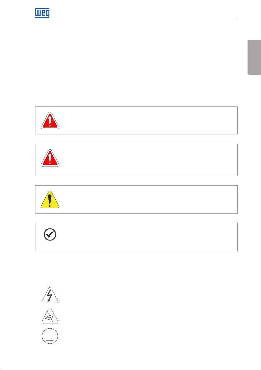
1.2 SAFETY WARNINGS IN THE PRODUCT
The following symbols are attached to the product, serving as safety notices:
High voltages are present.
Components sensitive to electrostatic discharge.
Do not touch them.
Mandatory connection to the protective ground (PE).
CFW701 | 1
Page 7
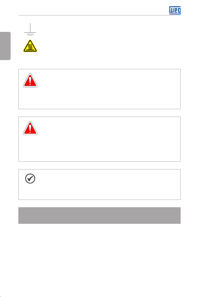
Safety Instructions
Connection of the shield to the ground.
English
Hot surface.
1.3 PRELIMINARY RECOMMENDATIONS
DANGER!
Always disconnect the main power supply before touching any electrical
device associated with the inverter. Several components may remain charged
with high voltage and/or in movement (fans), even after the AC power supply
has been disconnected or turned off. Wait at least 10 minutes to guarantee
the fully discharge of capacitors. Always connect the equipment frame to the
ground protection (PE).
DANGER!
Débranchez toujours l'alimentation principale avant d'entrer en contact avec un
appareil électrique associé au variateur. Plusieurs composants peuvent rester
chargés à un potentiel électrique élevé et/ou être en mouvement (ventilateurs),
même après la déconnexion ou la coupure de l'alimentation en courant alternatif.
Attendez au moins 10 minutes que les condensateurs se déchargent
complètement.
Raccordez toujours la masse de l'appareil à une terre protectrice (PE).
Do not perform a withstand voltage test on any part of the inverter!
2 | CFW701
NOTE!
Frequency inver ters may cause interference in other electronic devices. Follow
the recommendations listed in chapter 3 INSTALLATION AND CONNECTION
on page 9, to minimize these effects.
Fully read this manual before installing or operating the inverter.
If needed, please, consult WEG.
Page 8

General Instructions
2 GENERAL INSTRUCTIONS
2.1 ABOUT THE MANUAL
The purpose of this manual is to provide the basic information needed to install, start-up in
the V/f control mode (scalar), and troubleshoot the most common problems of the CFW701
frequency inverter series.
ATTENTION!
The operation of this equipment requires installation instructions and
detailed operation provided in the user's manual, programming manual and
communication manuals. The user's manual and the parameters quick reference
are supplied in a hard copy together with the inverter. The user guides are
also provided in a hard copy along with the accessories. The other manuals
are included on the CD supplied with the inverter or can be downloaded from
the WEG website at - www.weg.net. The CD should always be kept with the
equipment. A printed copy of the files available on the CD can be ordered
through your local WEG representative.
Some of the figures and tables are available in the appendixes. The APPENDIX A - DIAGRAMS AND
FIGURES on page 138 shows the figures and the APPENDIX B - TECHNICAL SPECIFICATIONS
on page 148 shows the technical specifications. The information is available in three languages.
Please refer to the following technical manuals for further information:
CFW701 Programming Manual.
English
Modbus Communication Manual.
BACnet Communication Manual.
2.2 ABOUT THE CFW701
The CFW701 frequency inverter is a high performance product designed for speed and torque
control of threephase induction motors. The main characteristic of this product is the “Vectrue”
technology, which has the following advantages:
Scalar control (V/f), VVW, or vector control programmable in the same product.
The vector control may be programmed as “sensorless” (which means standard motors
without using encoders).
The “sensorless” control allows high torque and fast response, even in very low speeds or at
the starting.
“Optimal Braking” function for the vector control, allowing the controlled braking of the motor
and avoiding external braking resistor for some applications.
“Self-Tuning” feature for vector control. It allows the automatic adjustment of the regulators
and control parameters from the identification (also automatic) of the motor parameters and
load.
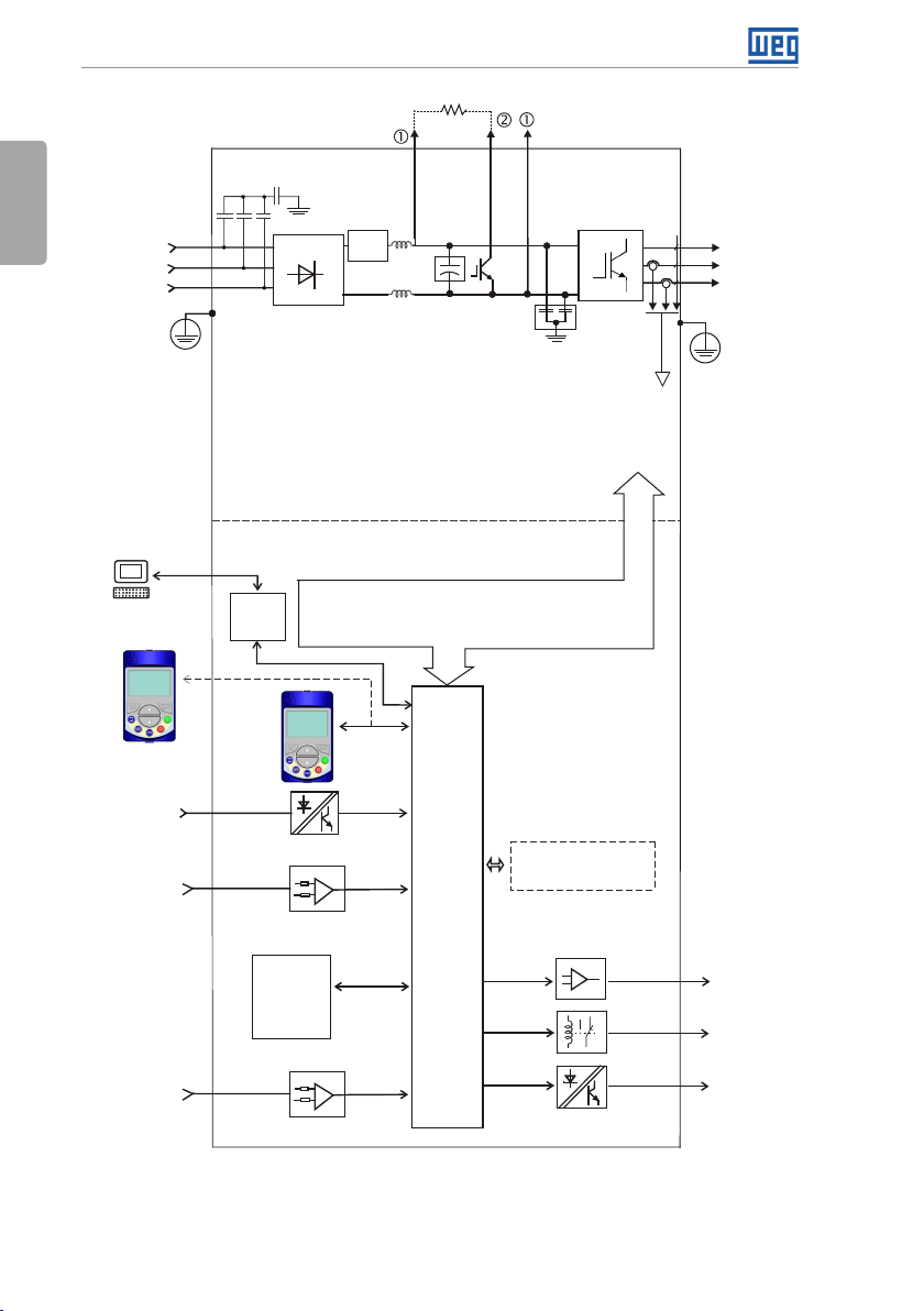
The main components of the CFW701 can be viewed in Figure A.1 on page 138.
CFW701 | 3
Page 9
General Instructions
English
C3 RFI filter
= DC bus connection
= Braking resistor
DC+ DC-BR
(*)
connection
Mains power
supply
PC
WPS software
WLP software
Keypad
(remote)
Digital inputs
DI1 to DI8
Analog
inputs
AI1 to AI3
R/L1/L
S/L2/N
T/L 3
PE
RS-485
Three-phase
rectifier
Pre-
charge
DC link chokes
DC link capacitor bank
CFW701...DB... inver ters)
Braking IGBT (available in
POWER
CONTROL
Control power supply and interfaces
between power and control
Keypad
CC701
Control
board
with a
32 bits
"RISC"
CPU
RFI filter
transistors
Accessories
COMM 1
(Slot 3 - green)
Inverter
with
IGBT
Feedback:
- voltage
- current
U/T1
V/T2
W/T3
Motor
PE
PTC
protection
input
4 | CFW701
FLASH
memor y
module
(Slot 5)
= Keypad (HMI)
(*) The capacitor to the ground of the C3 RFI filter (it is possible to meet the
requirements of category C2 with this filter on frame size A models) must be
disconnected for IT net works and grounded delta power supplies. Please
refer to item 3.2.3.1 Input Connections on page 14.
Figure 2.1: Block diagram for the CFW701
Analog
outputs
AO1 and AO2
Digital outputs
DO1 (RL1) and
DO2 (RL2)
Digital outputs
DO3 to DO5
Page 10
General Instructions
2.3 IDENTIFICATION
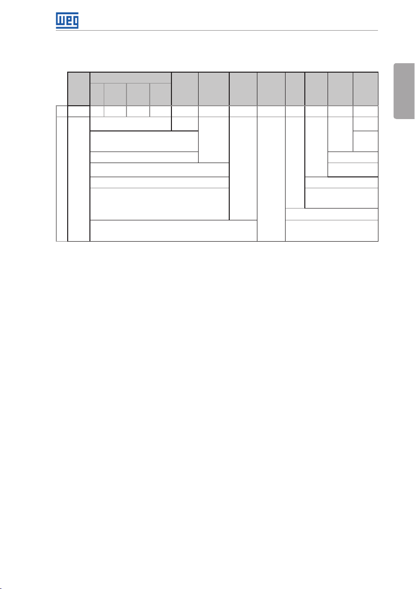
Table 2.1: Identification of the CFW701 inverters
Product
and
Series
Eg.: CFW701 A 03P6 T 4 DB 20 C3 DS Y1 W1 --- --
CFW701
Available options
Notes:
(1) The options available for each model are shown in Table 2.2 on page 6.
(2) This option is not available for 200...240 V and 380...480 V models of frame size D inverters (the standard product is
Ne ma1).
(3) This option is not available for frame size A inverters with N1 (Nema1 enclosure) or IP21 options.
(4) It is possible to meet the requirements of catego ry C2 with this fi lter on frame size A models. For fur ther details, see Table
B.6 on page 163.
(5) Only applicable to models with degree of protection IP55, option N12.
Model Identification
Rated
Output
Current
(4)
(2)
Number
of Power
Phases
Rated
Volta ge
Frame
Size
Refer to Table 2.2 on p age 6.
NB = withou t dynamic braki ng (valid only for
frame size E inverters and 50 0...60 0 V models
of frame si ze D).
DB = with dy namic braking. Blank = standard.
20 = IP20
21 = IP21 (not availa ble for frame size E inverter s). Blank = not available.
N1 = Nema1 enclos ure (UL Type 1) (protection de gree
accordi ng to IEC: IP21 for frame size s A, B and C and IP20
for frame s izes D and E).
N12 = IP55 (only for 200...240 V and 3 80...4 80 V models of
frame sizes B, C, D and E).
C3 = accord ing to category 3 (C3) of IEC 61800-3, wi th built-in C3 RFI
fil ter.
Braking
(1)
Enclosure
Conducted
(1)
Emission
Level
(1)
Safet y
Discon.
Switc h
Blank = not
available
DS = with
discon.
switch
External
Stop
Control
(5)
(3)
Volta ge
W1 = 24 Vdc power supply,
indepe ndent of the control
voltage.
Blank = not available.
Y1 = with STO function (Safe Torqu e Off)
accordi ng to EN 954-1/ ISO 13849-1,
category 3.
Special
Special
Hardware
Software
Versi on
Versi on
Blank =
standard.
Sx =
special
software.
Hxx or K xx = special
hardware.
English
CFW701 | 5
Page 11
General Instructions
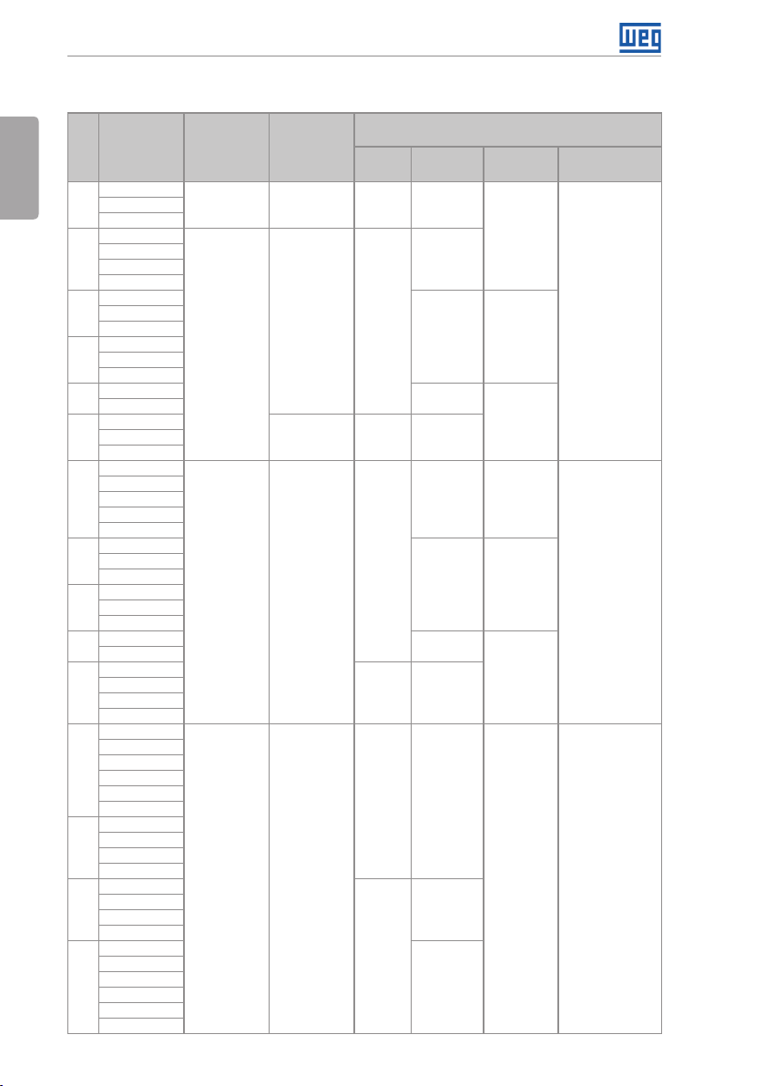
Table 2.2: Options available for each model according to the frame size, power supply, rated current and
voltage of the inverter
Available Options for the Remaining Identification
Braking
DB
NB or DB 20, N1 o r N12
DB 20, 21 or N1
NB or DB
Frame
Size
A
A
B
C
D
E
A
B
C
D
E
B
C
D
E
Rated Output
Curre nt for ND
Overload
06P0 = 6.0 A
07P0 = 7.0 A
10P0 = 10 A
07P0 = 7.0 A
10P0 = 10 A
13P0 = 13 A
16P0 = 16 A
24P0 = 24 A
28P0 = 28 A
33P5 = 33.5 A
45P0 = 45 A
54P0 = 54 A
70P0 = 70 A
86P0 = 8 6 A
0105 = 105 A
0142 = 142 A
02 11 = 211 A
03P6 = 3.6 A
05P0 = 5.0 A
07P0 = 7.0 A
10P0 = 10 A
13P5 = 13.5 A
17P0 = 17 A
24P0 = 24 A
31P0 = 31 A
38P0 = 3 8 A
45P0 = 45 A
58P5 = 58.5 A
70P5 = 70.5 A
88P0 = 8 8 A
0105 = 105 A
0142 = 142 A
0180 = 180 A
02 11 = 211 A
02P9 = 2.9 A
04P2 = 4.2 A
07P0 = 7.0 A
10P0 = 10 A
12P0 = 12 A
17P0 = 17 A
22P0 = 22 A
27P0 = 27 A
32P0 = 32 A
44P0 = 44 A
22P0 = 22 A
27P0 = 27 A
32P0 = 32 A
44P0 = 44 A
53P0 = 53 A
63P0 = 63 A
80P0 = 80 A
0107 = 107 A
0125 = 125 A
0150 = 150 A
Number of
Power Phases
S = Single-phase 2 = 200…240 V DB 20, 21 or N1
T = three-phase
T = three-phase 4 = 380...480 V
T = three-phase 5 = 500...600 V
Rated Voltage
2 = 200…240 V DB
2 = 220 / 230 V NB or DB 20, N1 or N120180 = 180 A
English
Codes o f the Inverte rs
(standard product is shown in bold)
Enclosure
(protection
degree)
20, 21 or N1
20, 21, N1
21, N1 o r N12
20, 21 or N1 Blank
20, 21, N1
21, N1 o r N12
20, 21 or N1
20 or N1
or N 12
or N 12
Disconnecting
Switch
Blank
Blank or DS
Blank o r DS
Blank or DS
Blank o r DS
Blank C3
Conducted Emission
Level
C3
C3
6 | CFW701
Page 12
General Instructions
2.4 LIST OF AVAILABLE MODELS
The available inverter models are listed in Table B.1 on page 148, Table B.2 on page 149
and Table B.3 on page 150.
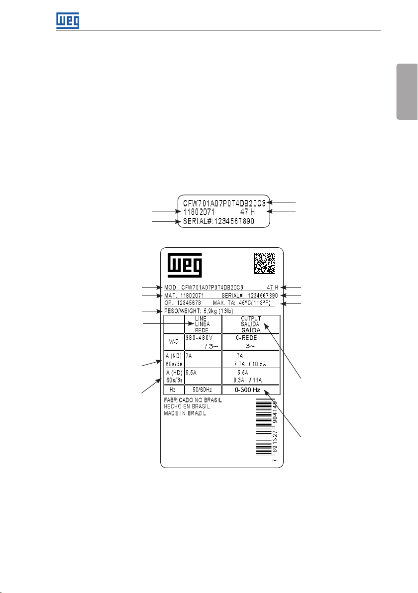
2.5 IDENTIFICATION LABELS
There are two nameplates on the CFW701: one complete nameplate is affixed to the side of the
inverter and a simplified one is located under the keypad. Please refer to Figure A.2 on page
139 to verify the position of these labels on the product. The nameplate under the keypad
allows the identification of the most important characteristics of the inverter even if they are
mounted side-by-side. When there is more than one inverter it is necessary to be careful not to
exchange the inverter covers (front cover in case of inverters frame sizes A, B or C and control
rack cover for inverters frame sizes D and E) because there are individual information labels
under the keypad of each inverter.
CFW701 model
Manufacturing dateWEG part number
Serial number
(a) Nameplate located under the keypad
CFW701 model
WEG part number
Inverter net weight
Input rated data (voltage,
number of phases, rated
currents for operation with
ND and HD overload cycles,
and frequency)
Current specifications
for operation with normal
overload cycle (ND)
Current specifications
for operation with heavy
overload cycle (HD)
(b) Nameplate affixed to the side of the inverter
Figure 2.2: (a) and (b) Nameplates
Manufacturing date
Serial number
Maximum ambient
temperature (without
derating) for ND overload
with open spaces for
ventilation around the
inverter (refer to the
dimensions A, B, C and
D in Figure B.3 on page
171)
Output rated data
(voltage, number of
phases, rated currents for
operation with ND and HD
overload cycles, overload
currents for 1 min and 3 s,
and frequency range)
The maximum output
frequency depends on the
settings of the motor rated
frequency, control mode
and inverter switching
frequency. For fur ther
details, see Table 8.1 on
page 40.
English
2.6 RECEIVING AND STORAGE
The CFW701 comes packaged in a cardboard box up to frame size C inverter models. The
bigger models are packed in wooden box. There is an identification label affixed to the outside
of this package, the same one that is affixed to the side of the CFW701 inverter.
CFW701 | 7
Page 13
General Instructions
Follow the steps below to open the packaging of models larger than frame size C:
1. Put the shipping container over a flat and stable area with the assistance of another two
people.
English
2. Open the wood crate.
3. Remove all the packing material (the cardboard or styrofoam protection) before removing
the inverter.
Check the following items once the inverter is delivered:
Verify that the CFW701 nameplate corresponds to the model number on your purchase order.
Inspect the CFW701 for external damage during transportation.
Report any damage immediately to the carrier that delivered your CFW701 inverter.
If CFW701 is to be stored for some time before use, be sure that it is stored in a clean and dry
location that conforms to the storage temperature specification (between -25 °C and 60 °C
(-13 °F and 140 °F)). Cover the inverter to prevent dust accumulation inside it.
ATTENTION!
Capacitor reforming is required if drives are stored for long periods of time
without power. Refer to section 6.4 PREVENTIVE MAINTENANCE on page 32.
8 | CFW701
Page 14

3 INSTALLATION AND CONNECTION
3.1 MECHANICAL INSTALLATION
3.1.1 Installation Environment
Installation and Connection
Avoid installing the inverter in an area with:
Direct exposure to sunlight, rain, high humidity, or sea-air.
Inflammable or corrosive gases or liquids.
Excessive vibration.
Dust, metallic particles, and oil mist.
Environment conditions for the operation of the inverter:
Inverter surrounding temperature: from -10 ºC up to Ta according to the Table B.4 on page
152.
For temperatures around the inverter greater than Ta and smaller than 60 °C (140 °F) (frame
sizes A, B, C and D), 40 °C (104 °F) (models with degree of protection IP55) and 55 °C (133 °F)
(frame size E), it is necessary to apply current reduction of 2 % for every degree Celsius (or
1.11 % each °F) up to Ta.
Humidity: from 5 % to 95 % non-condensing.
Altitude: up to 1000 m (3.300 ft) - standard conditions (no derating required).
From 1000 m to 4000 m (3.300 ft to 13.200 ft) - current derating of 1 % each 100 m (or 0.3 %
each 100 ft) above 1000 m (3.300 ft) altitude.
From 2000 m to 4000 m (6.600 ft to 13.200 ft) above sea level - maximum voltage reduction
(240 V for 200...240 V models, 230 V for 220...230 V models, 480 V for 380...480 V models
and 600 V for 500 ...600 V models) of 1.1 % for each 100 m (330 ft) above 2000 m (6.600 ft).
English
Pollution degree: 2 (according to EN50178 and UL508C) with non-conductive pollution.
Condensation shall not originate conduction through the accumulated residues.
3.1. 2 Mounting Considerations
External dimensions, fixing holes position and net weight of the inverter are presented at Figure
B.2 on page 169 and Figure B.3 on page 171. Please refer to Figure B.4 on page 172 to
Figure B.10 on page 178 for more details of each inverter frame size.
Install the inverter upright on a flat surface. First place the screws on the surface where the
drive is going to be installed, install the drive and then tighten the screws.
Frame size E inverters with N1 option (CFW701E...N1...):
After fixing the inverter, install the upper Nema 1 kit on the inverter using the two M8 screws
provided with the product.
CFW701 | 9
Page 15
Installation and Connection
Let the minimum clearances specified in Figure B.3 on page 171 in order to allow air circulation
for cooling. It is possible to assembly frame sizes A, B and C inverters with IP20 protection
degree (CF W701… 20…) side by side without lateral spacing, i.e., with the D distance presented
English
in Figure B.3 on page 171 equal to zero.
Do not install heat sensitive components right above the inverter.
ATTENTION!
When arranging two or more inverters vertically, respect the minimum
clearance A + B (Figure B.3 on page 171) and provide an air deflecting
plate so that the heat rising up from the bottom inverter does not affect the
top inverter.
Provide conduit for physical separation of the signal, control, and power
conductors (refer to section 3.2 ELECTRICAL INSTALLATION on page 10).
Please refer to Figure B.3 on page 171 for surface and flange mounting data. The inverter
dissipated power at rated condition for surface and flange mounting is presented in Table B.4
on page 152. Remove the drive mounting brackets for flange mounting. The protection degree
of the inverter outside the panel is IP55 for flange mounting. It is necessary to provide proper
seal for the opening where the inverter is installed to ensure the protection degree of the panel.
Example: sealing with silicone.
Please refer to Figure A.4 on page 141 for more details on the access to the control and
power terminals.
3.2 ELECTRICAL INSTALLATION
10 | CFW701
DANGER!
The following information is merely a guide for proper installation. Comply
with applicable local regulations for electrical installations.
Make sure the AC power supply is disconnected before starting the
installation.
DANGER!
Les informations suivantes constituent uniquement un guide pour une
installation correcte. Respectez les réglementations locales en vigueur pour
les installations électriques.
Vérifiez que l'alimentation secteur CA est débranchée avant de commencer
l'installation.
Page 16
Installation and Connection
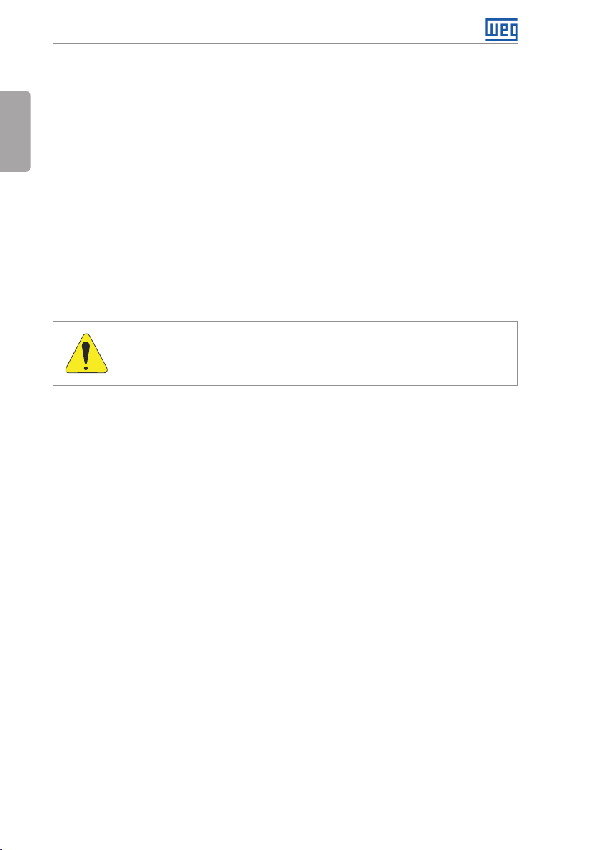
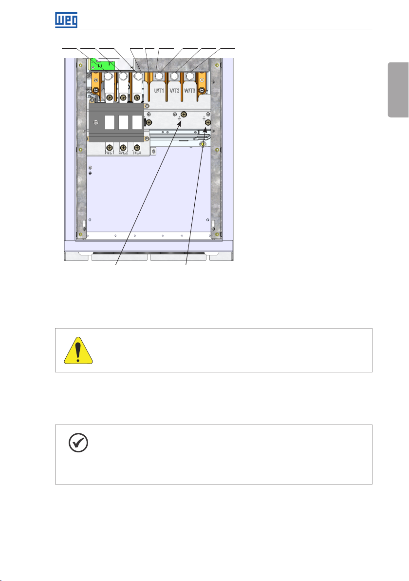
3.2 .1 Identification of the Power and Grounding Terminals
R/L1 S/L2 T/L3 DC- DC+ U/ T1 V/ T2 W/T3BR
GroundGround
(a) Frame sizes A, B and C
R/L1 S/L2 T/L3 DC- DC+ U/ T1 V/ T2 W/T3BR
R/L1, S/L2, T/L3: AC power supply.
DC-: this is the negative potential
terminal in the DC bus circuit.
BR: braking resistor connection.
DC+: this is the positive potential
terminal in the DC bus circuit.
U/T1, V/T2, W/T3: motor
connection.
English
Ground
(b) Frame sizes B and C with degree of protection IP55
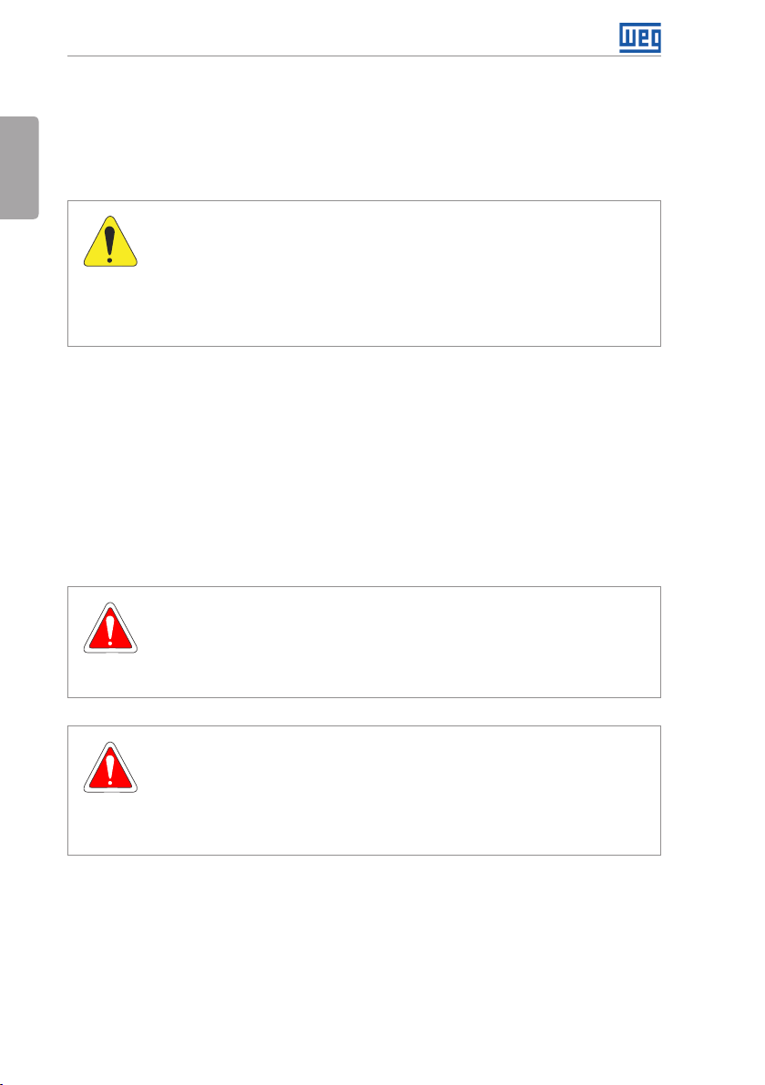
R/L1 S/L2 T/ L3 DC- DC+ U/T1 V/T2 W/ T3
Ground
(c) Frame size D
Ground
BR
Ground
CFW701 | 11
Page 17
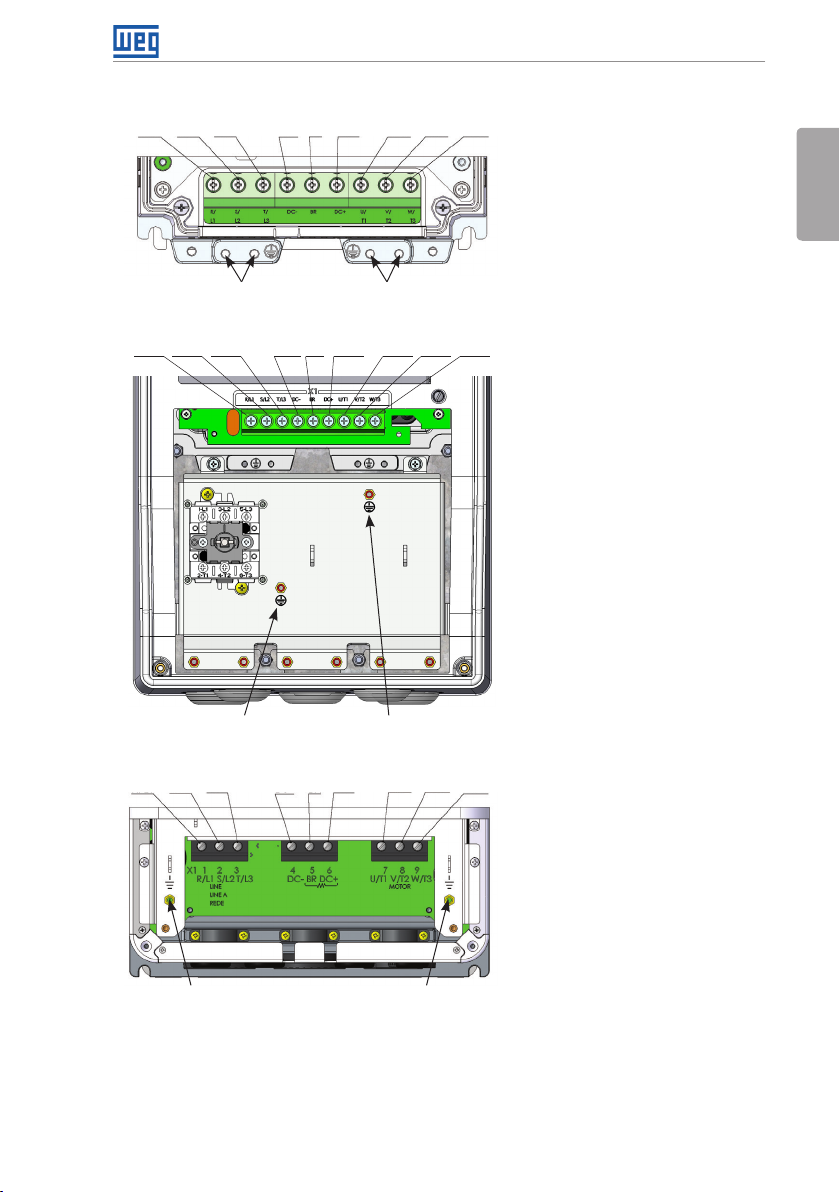
Installation and Connection
R/L1 S/L2 T/L3 DC- DC+ U/ T1 V/ T2 W/T3BR
English
(d) Frame size D with degree of protection IP55
Ground Ground
R/L1, S/L2, T/L3: AC power supply.
U/T1, V/T2, W/T3: motor
connection.
DC+: this is the positive potential
terminal in the DC bus circuit.
BR: braking resistor connection.
DC-: this is the negative potential
terminal in the DC bus circuit.
12 | CFW701
Ground
(4xM8, 4xM5)
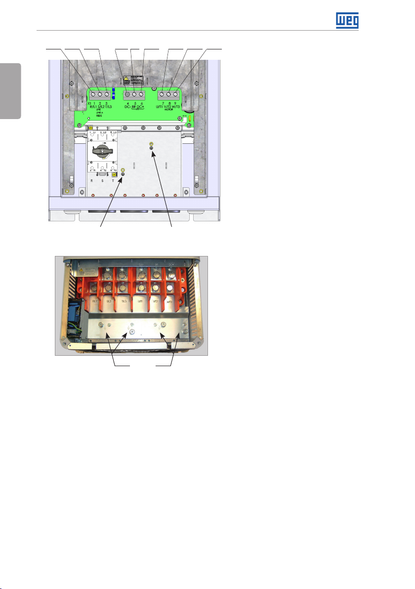
(e) Frame size E
Page 18
R/L1 S/L2 T/L3 DC- DC+ U/ T1 V/ T2 W/T3BR
Ground Ground
(f) Frame size E with degree of protection IP55
Figure 3.1: (a) to (f) Power terminals and grounding points – frame sizes A to E
Installation and Connection
English
3.2.2 Power / Grounding Wiring and Fuses
ATTENTION!
Use proper cable lugs for the power and grounding connection cables.
Refer to Table B.1 on page 148, Table B.2 on page 149 and Table B.3 on page 150 for
the recommended wiring and fuses and Table B.5 on page 160 for the specifications of the
power terminals.
NOTE!
The gauges values presented in Table B.1 on page 148, Table B.2 on page
149 and Table B.3 on page 150 are for reference only. Installation conditions
and the maximum permitted voltage drop shall be considered for the proper
wiring sizing.
Input fuses
The fuses to be used at the input must be HS (High-Speed) type with I
value indicated in the Table B.1 on page 148, Table B.2 on page 149 and Table B.3 on
page 150 (consider extinction current value in cold situation (it is not the fusion value)), to
protect the inverter diode rectifiers and input wiring.
2
t equal or lower the
CFW701 | 13
Page 19
Installation and Connection
In order to meet UL requirements, use class J fuses at the inverter supply with a current not
higher than the values presented in Table B.1 on page 148, Table B.2 on page 149 and
Table B.3 on page 150 .
English
Optionally, slow blow fuses can be used at the input. They shall be sized for 1.2 x the rated
input current of the inverter. In this case, the installation is protected against short-circuit, but
not the inverter input rectifier. This may result in major damage to the inverter in the event of
an internal component failure.
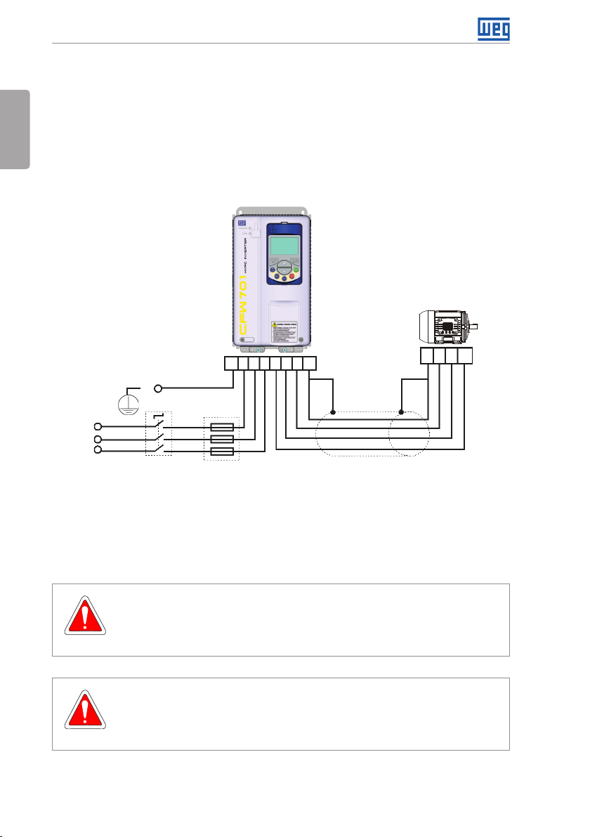
3.2.3 Power Connections
PE R S T U V W PE
PE
Shielding
R
S
T
Power
supply
The switch-disconnector is not necessary if the inverter has the DS optional item (with
Disconnect
switch
Fuses
Figure 3.2: Power and grounding connections
PE W V U
switch-disconnector).
3.2.3.1 Input Connections
DANGER!
Provide a disconnect device for the input power supply of the inverter.
This device shall disconnect the input power supply for the inver ter when needed
(for instance, during servicing).
DANGER!
Montez un dispositif de coupure sur l'alimentation du variateur.
Ce composant déconnecte l'alimentation du variateur si cela est nécessaire
(ex. pendant l'entretien et la maintenance).
14 | CFW701
Page 20
Installation and Connection
ATTENTION!
The power supply that feeds the inverter shall have a solid grounded neutral.
In case of IT networks, follow the instructions described below.
ATTENTION!
In order to be able to use the CFW701 with built-in C3 RFI filter (CFW701…
C3…) in IT networks (neutral conductor not grounded or grounded via a high
ohmic value resistor) or in corner-grounded delta systems, it is necessary to
remove some RFI filter components (capacitor for frame sizes A, B, C and
D and capacitor and the MOV for frame size E) connected to the ground by
removing the screws indicated in Figure A.6 on page 142 for inverter frame
sizes A, B, C and D and changing the position of the J1 jumper on the PRT1
board from (XE1) to “NC” (XIT), according to the Figure A.6 on page 142
for inverter frame size E.
AC power supply considerations
Suitable for use on a circuit capable of delivering not more than 100.000 A
Ampères at 240 V, 480 V or 600 V maximum, when protected by Class J fuses (for 240 V
symmetrical
rms
and 480 V models) or special purpose fuses (for 600 V).
In case the CFW701 is installed in power supplies with current capacity higher than 100.000 A
it is necessary to provide adequate protections circuits such as fuses or switches.
rms
3.2.3.2 Dynamic Braking (standard built-in for frame sizes A, B, C and D and optional built-in for frame size E - CFW701...DB...)
Refer to Table B.1 on page 148, Table B.2 on page 149 and Table B.3 on page 150 for
the following dynamic braking specifications: maximum current, resistance, RMS current and
cable gauges.
The power rating of the dynamic braking resistor is a function of the deceleration time, the load
inertia and the resistant torque.
English
,
Dynamic braking installing procedure:
Install the braking resistor between the power terminals DC+ and BR.
Use twisted cable for the connection. Separate these cables from the signal and control
cables.
Size the cables according to the application, respecting the maximum and effective currents.
If the braking resistor is installed inside the inverter cabinet, consider its additional dissipated
energy when sizing the cabinet ventilation.
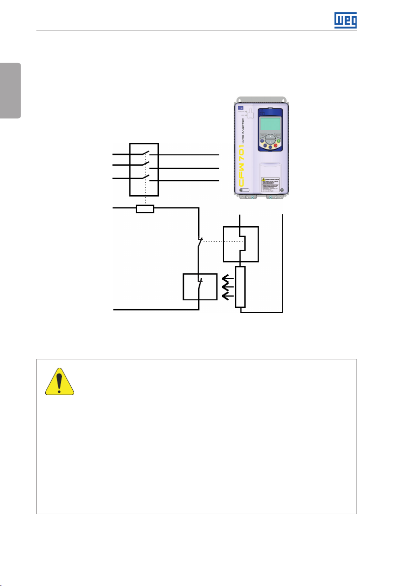
The thermal protection of the dynamic braking resistor must be provided externally using a
thermal relay in series with the resistor and/or a thermostat in contact with the resistor frame,
connected so as to switch the input power supply of the inverter, as shown in Figure 3.3 on
page 16.
CFW701 | 15
Page 21
Installation and Connection
Set P0151 and P0185 to their maximum values (400 V or 800 V) when using dynamic braking.
English
The DC link voltage actuation level of the dynamic braking is set by parameter P0153 (Dynamic
Braking Level).
Power
supply
Control power
supply
3.2.3.3 Output Connections
CFW701
Contactor
R
S
T
BR
Thermal
relay
Thermostat
Figure 3.3: Connection of the braking resistor
DC+
Braking
resi stor
16 | CFW701
ATTENTION!
The inverter has an electronic motor overload protection that shall be adjusted
according to the driven motor. When several motors are connected to the
same inverter, install individual overload relays for each motor.
The motor overload protection available for the CFW701 is in accordance
with UL508C as per the following information:
- Trip current equal to 1.25 times the motor rated current (P0401) adjusted
in the oriented start-up menu.
- The maximum value of P0398 (Motor Service Factor) is 1.15.
- Parameters P0156, P0157 and P0158 (Overload Current at 100 %,
50 % and 5 % of the rated speed, respectively) are automatically adjusted
when the parameters P0401 (Motor Rated Current) and/or P0406 (Motor
Ventilation) are changed on the “Oriented Start-up” menu. If the parameters
P0156, P0157 and P0158 are set manually, the maximum allowed value
is 1.05 x P0401.
Page 22
Installation and Connection
ATTENTION!
If a disconnect switch or a contactor is installed between the inverter and the
motor, never operate them with a spinning motor or with voltage at the inverter
output.
The characteristics of the cable used for the inverter and motor interconnection, as well as
the physical location are extremely important to avoid electromagnetic interference in other
equipment and to not affect the life cycle of motor windings and motor bearings controlled by
inverters.
Keep motor cables away from other cables (signal cables, sensor cables, control cables, etc.),
according to item 3.2.6 Cable Distances on page 22.
Connect a fourth cable between the motor ground and the inverter ground.
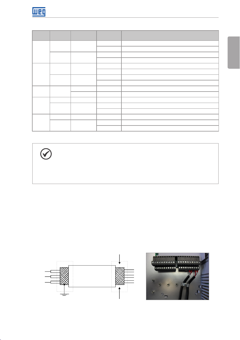
When using shielded cables for connecting the motor:
Follow the recommendations of IEC60034-25.
Use low impedance connection to high frequencies to connect the cable shield to ground.
Using parts supplied with the drive. See item below.
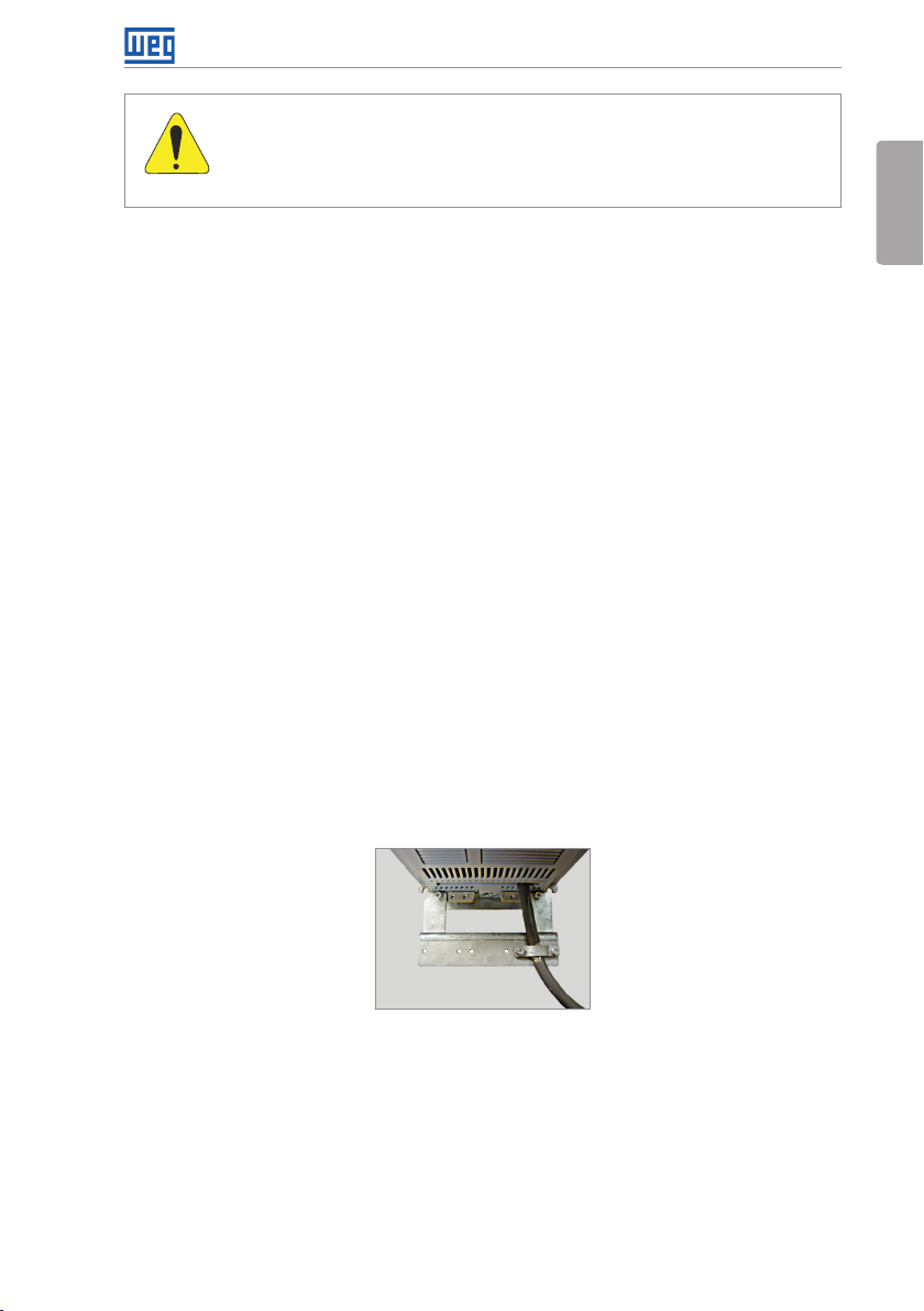
For inverter frame sizes A, B and C there is an accessory called “Shielding kit for power
cables PCSx-01” (see section 7.2 ACCESSORIES on page 37), which can be mounted at
the bottom of the cabinet – the Figure 3.4 on page 17 shows an example. The shielding
kit for power cables PCSx-01 goes along with inverters with optional internal C3 RFI filter
(CFW701...C3...). The grounding for the motor cable shield on inverter frame sizes D and E
is already provided in the standard inverter cabinet. This is also provided on the “Nema1
Kits (KN1x-01)” of the inverter frame sizes A, B and C.
For frame sizes B and C with degree of protection IP55, the accessory "PCSC-03 power
cable shield kit" is available, and for frame size D and E with degree of IP55 use the standard
accessories for shielding. The PCSC-03 shield kit comes with the inverter as optional item N12.
English
Figure 3.4: Motor cable shielding connection with PCSx-01 accessory
CFW701 | 17
Page 23
Installation and Connection
3.2.4 Grounding Connections
English
DANGER!
The inverter shall be connected to a Protective Ground (PE).
Use the minimum ground wiring gauge as indicated in the Table B.1 on page
148 , Table B.2 on page 149 and Table B.3 on page 150.
Connect the inverter grounding connections to a ground bus bar, to a single
ground point, or to a common grounding point (impedance ≤ 10 Ω).
The neutral conductor of the network shall be solidly grounded; however,
this conductor shall not be used to ground the inverter.
It is necessary to use a copper cable with 10 mm
2
minimum or 2 cables with
the same wire gauge as specified in Table B.1 on page 148, Table B.2 on
page 149 and Table B.3 on page 150 for connecting the inverter to the
ground protection to be in accordance with IEC61800-5-1 since the leakage
current is greater than 3.5 mA AC.
DANGER!
Le variateur doit être raccordé à une terre de protection (PE).
Utilisez la section minimale de raccordement à la terre indiquée dans les Ta b l e
B.1 à la page 148, Table B.2 à la page 149 et Table B.3 à la page 150.
Connectez la masse du variateur à une barre collectrice de terre en un seul
point ou à un point commun de raccordement à la terre (impédance ≤ 10 Ω).
Le conducteur neutre doit être solidement raccordé à la terre; néanmoins,
ce conducteur ne doit pas s'utiliser pour raccorder le variateur à la terre.
Il est nécessaire d'utiliser un câble de section minimale 10 mm
2
ou 2 câbles
de section identique (voir les Table B.1 à la page 148, Table B.2 à la page
149 et Table B.3 à la page 150 pour raccorder le variateur à la terre
conformément à la norme IEC61800-5-1 du fait que le courant de fuite
alternatif est supérieur à 3.5 mA.
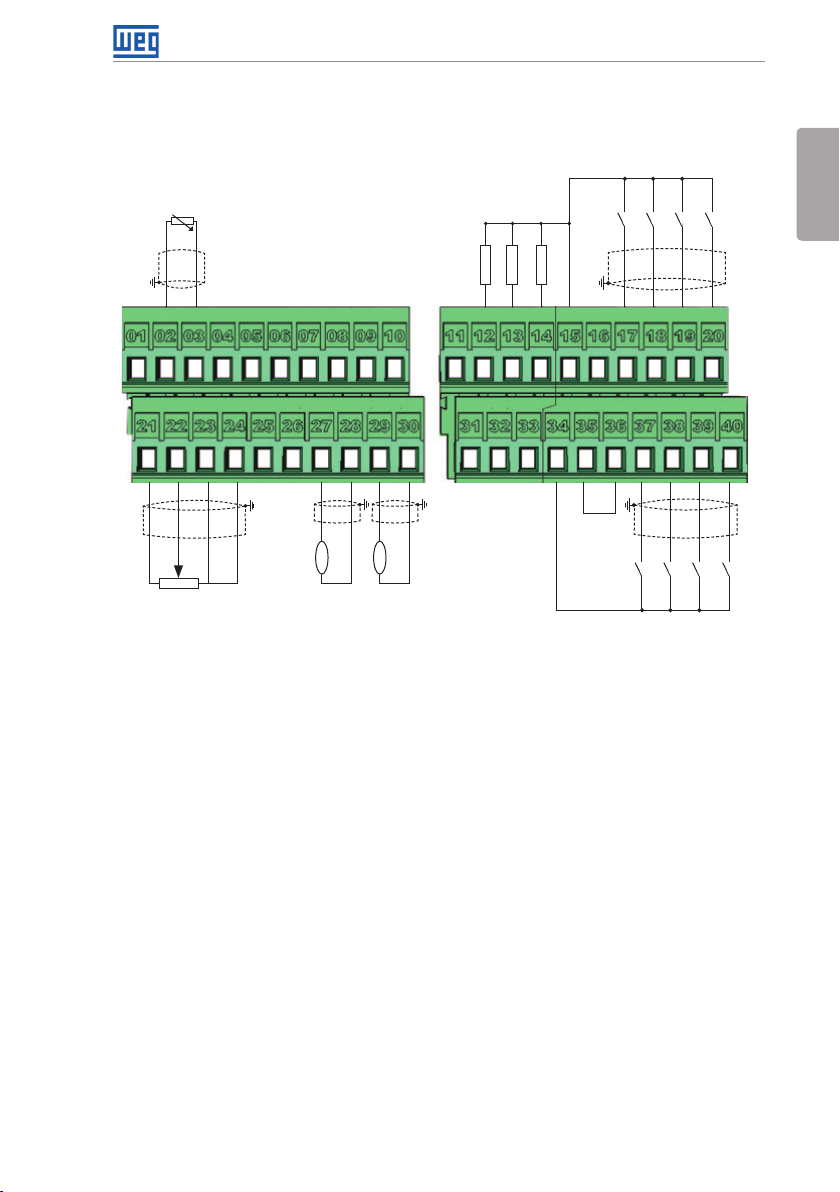
3.2.5 Control Connections
The control connections (analog inputs/outputs and digital inputs/outputs), shall be performed
in connector XC1 of the CC701 control board. Functions and typical connections are presented
in Figure 3.5 on page 20.
18 | CFW701
Page 24
Installation and Connection
NC
PTC
NC
NC
A - RS-485
B - RS-485
GND
AI3-
AI3+
AI2-
AI2+
DO3
RL2-C
RL2-NA
≥5 kΩ
AI1-
AI1+
REF+
(1) Refer to Figure 3.5 on page 20 for active low digital inputs connection.
REF-
rpm
AO1
amp
AO2
AGND (24 V)
AGND (24 V)
(a) Active high digital inputs
>300 Ω
RL1-C
Active high digital inputs
+24 V
DO4
DO5
>300 Ω
>300 Ω
RL1-NA
COM
+24 V
(1)
GND (24 V)
DI5
DI6
DI7
DI8
English
DI4
DI3
DI2
DI1
GND (24 V)
CFW701 | 19
Page 25
Installation and Connection
English
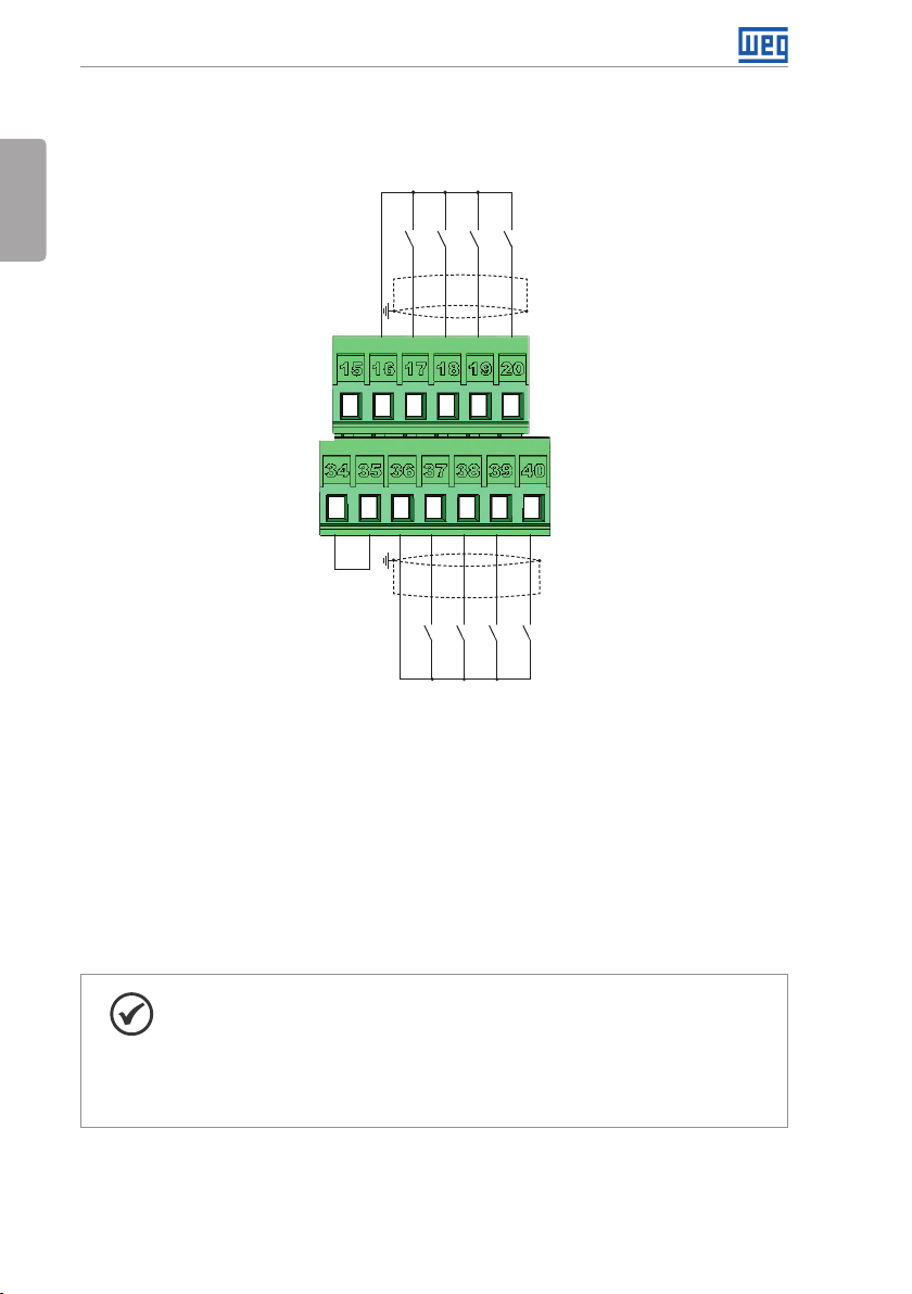
Active low digital inputs
+24 V
DI5
DI6
GND (24 V)
DI7
DI8
+24 V
COM
GND (24 V)
DI1
DI2
DI3
DI4
(b) Active low digital inputs
Figure 3.5: (a) and (b) XC1 connection terminals
Refer to Figure A.3 on page 139 to find the control board, the XC1 connector (control
signals), the S1 DIP-switches (to select the type of signal of the analog inputs and outputs)
and S2 (RS-485 network termination) and slots 3 and 5 for accessories (see section 7.2
ACCESSORIES on page 37).
The CFW701 inverters are supplied with the digital inputs configured as active high and the
analog inputs and outputs configured for voltage signal 0...10 V.
NOTE!
To be able to use the analog input and/or output as current signals, it is
necessary to change the switch S1 and the related parameters as per Table
3.1 on page 21. In order to set the analog inputs to bipolar voltage signal
(-10…10 V), it is necessary to set P0233 and P0238 according to Table 3.1 on
page 21. Refer to the CFW701 programming manual for more information.
20 | CFW701
Page 26
Installation and Connection
Table 3.1: Configuration of the switch for the analog input and output signals selection
Input/
Output
Signal
Voltage S1.2 = OFF
AI1
Current S1.2 = ON
Voltage S1.1 = OFF
AI2
Current S1.1 = ON
AI3 Current
Voltage S1.3 = ON
AO1
Current S1.3 = OFF
Voltage S1.4 = ON
AO2
Current S1.4 = OFF
(*) Factory setting.
S1 Switch
Settings
Signal
Range
(*)
0…10 V
(*)
-10…10 V P0233 = 4
P0233 = 0 (direct reference) or 2 (reverse reference).
Parameter Settings
0...20 mA P0233 = 0 (direct reference) or 2 (reverse reference).
4...20 mA P0233 = 1 (direct reference) or 3 (reverse reference).
(*)
0…10 V
(*)
-10…10 V P0238 = 4
P0238 = 0 (direct reference) or 2 (reverse reference).
0...20 mA P0238 = 0 (direct reference) or 2 (reverse reference).
4...20 mA P0238 = 1 (direct reference) or 3 (reverse reference).
- 0...20 mA P0243 = 0 (direct reference) or 2 (reverse reference).
- 4...20 mA P0243 = 1 (direct reference) or 3 (reverse reference).
(*)
0...10 V
(*)
P0253 = 0 (direct reference) or 2 (reverse reference).
0...20 mA P0253 = 0 (direct reference) or 2 (reverse reference).
4...20 mA P0253 = 1 (direct reference) or 3 (reverse reference).
(*)
0...10 V
(*)
P0256 = 0 (direct reference) or 2 (reverse reference).
0...20 mA P0256 = 0 (direct reference) or 2 (reverse reference).
4...20 mA P0256 = 1 (direct reference) or 3 (reverse reference).
NOTE!
Settings of the S2 switch:
S2.1 = ON and S2.2 = ON: RS-485 is ON.
S2.1 = OFF and S2.2 = OFF: RS-485 is OFF.
The factory default for the S2.1 and S2.2 switches are OFF.
Other combinations of switch S2 are not allowed.
English
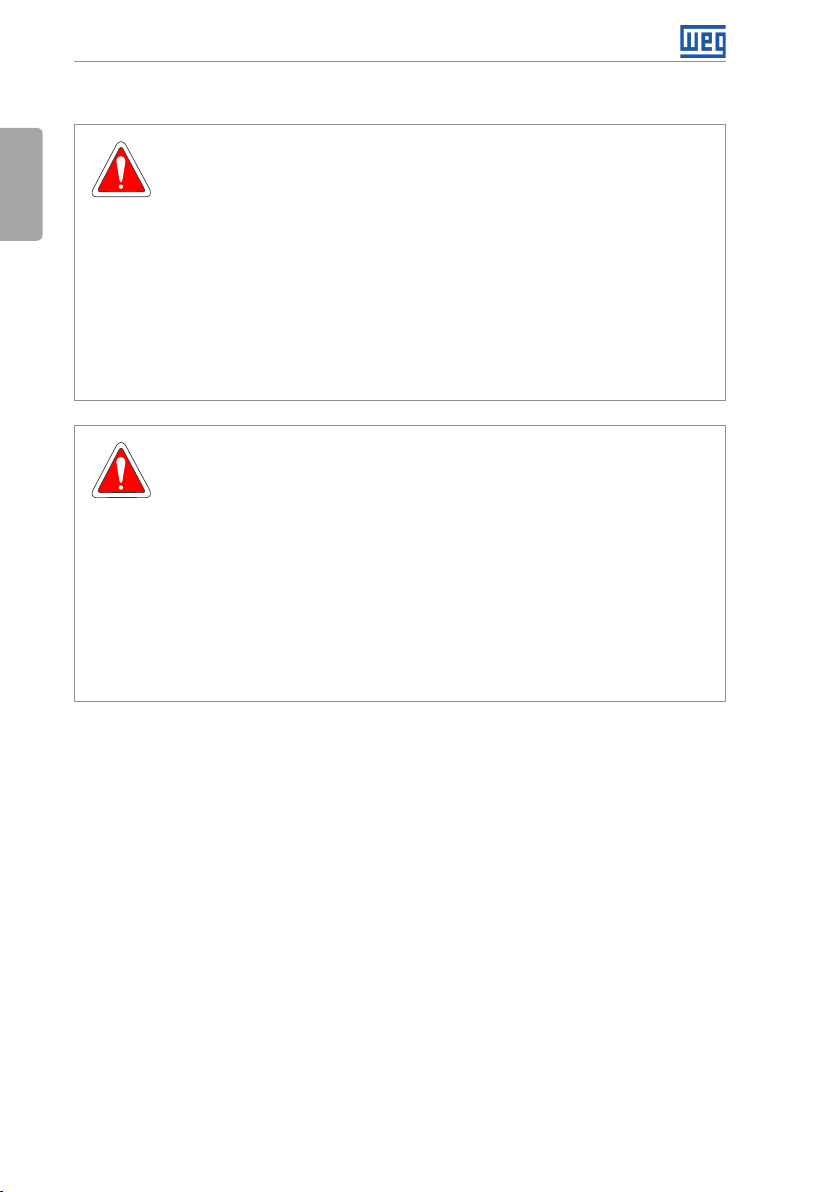
Follow instructions below for the proper installation of the control wiring:
1. Wire gauge: 0.5 mm² (20 AWG) to 1.5 mm² (14 AWG).
2. Maximum tightening torque: 0.50 N.m (4.50 lbf.in).
3. Use shielded cables for the connections in XC1 and run the cables separated from the remaining
circuits (power, 110 V / 220 Vac control, etc.), according to item 3.2.6 Cable Distances on page
22. If control wiring must cross other cables (power cables for instance), make it cross
perpendicular to the wiring and provide a minimum separation of 5 cm (1.9 in) at the crossing
point.
Refer to item 3.2.6 Cable Distances on page 22, for the proper cable distances.
Isolate with tape
Inverter
side
Do not ground
(a) Cable shield connection
(b) Connection sample of the shield to
ground
Figure 3.6: (a) and (b) Shield connection
CFW701 | 21
Page 27
Installation and Connection
4. Relays, contactors, solenoids or coils of electromechanical brakes installed close to the
inverter may eventually create interferences in the control circuitry. To eliminate this effect,
RC suppressors (with AC power supply) or free-wheel diodes (with DC power supply) shall
English
be connected in parallel to the coils of these devices.
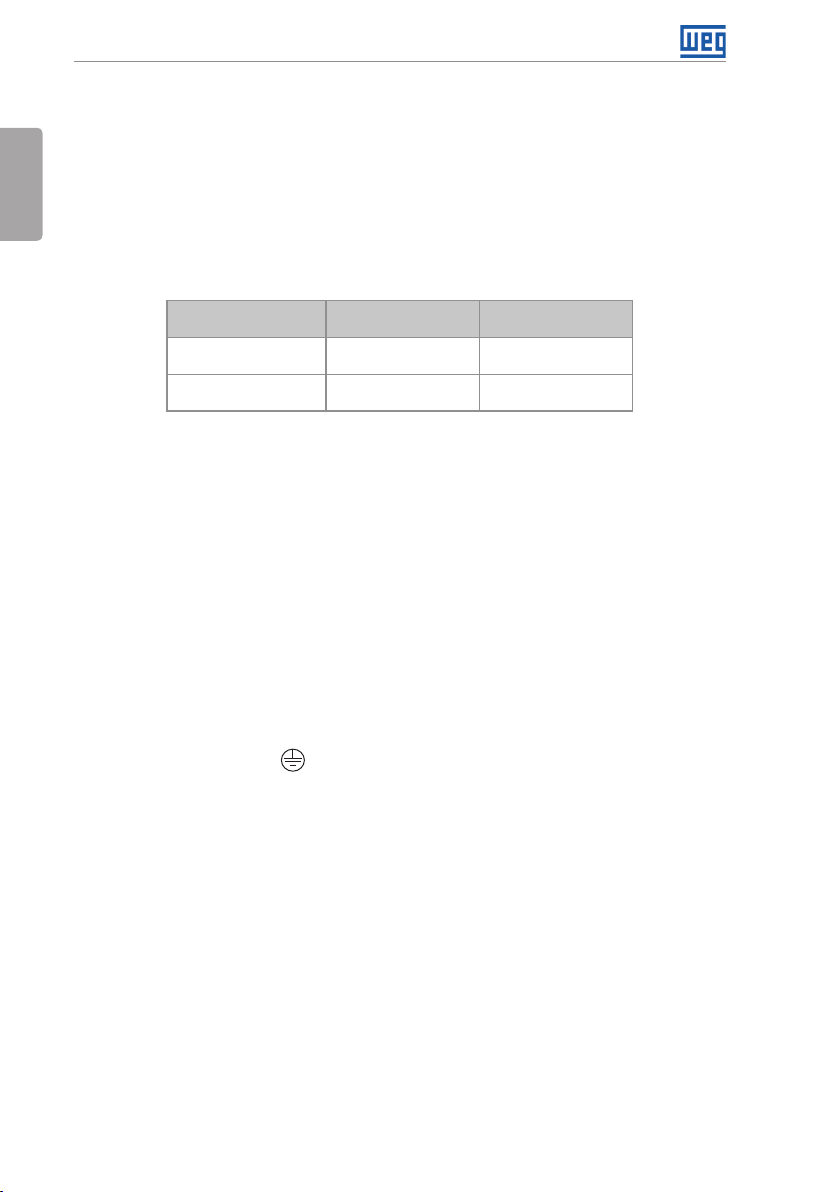
3.2.6 Cable Distances
The power cables and control cables must be separated (relay output cables and other control
cables) according to Table 3.2 on page 22.
Table 3.2: Cable distances
Rated Output
Inverter Current
≤ 24 A
≥ 28 A
Cable Length(s)
≤ 100 m (330 ft)
> 100 m (330 ft)
≤ 30 m (100 ft)
> 30 m (100 ft)
Minimum Separation
Distance
≥ 10 cm (3.94 in)
≥ 25 cm (9.84 in)
≥ 10 cm (3.94 in)
≥ 25 cm (9.84 in)
3.3 INSTALLATION ACCORDING TO THE EUROPEAN DIRECTIVE OF
ELECTROMAGNETIC COMPATIBILITY
All inverters have internal C3 RFI filter to reduce electromagnetic interference. These inverters,
when properly installed, meet the requirements of “EMC Directive 2004/108/EC”.
The CFW701 inverter series was developed for professional applications, applying the harmonic
emission limits defined by standards EN 61000-3-2 and EN 61000-3-12. The inverters meet the
EN 61000-3-2 requirements without restrictions and EN 61000-3-12 when installed in networks
with a drop lower than 1%.
3.3.1 Conformal Installation
1. Inverters with built-in C3 RFI filter CFW701...C3...
2. Frame sizes A to D inverters with built-in C3 RFI filter capacitors grounding screws and frame
size E with J1 cable in the position (XE1). For more information see Figure A.6 on page
142 .
3. Shielded output cables (motor cables) and connect the shield at both ends (motor and
inverter) with a low impedance connection for high frequency. Use PCSx-01 kit supplied with
frame sizes A, B and C inverters. For frame sizes B and C with degree of protection IP55,
use the PCSC-03 shield kit. For frame sizes D and E inverters use the clamps supplied with
the product. Ensure good contact between the cable shield and the clamps. Refer to Figure
3.4 on page 17 and keep the proper separation from other cables according to item 3.2.6
Cable Distances on page 22. The maximum motor cable length and conduction and
radiated emission levels are presented at Table B.6 on page 163. Use an external RFI filter
at the input of the inverter if necessary to have a lower emission level and/or a longer motor
cable length. For more information (RFI filter commercial reference, motor cable length and
emission levels) refer to Table B.6 on page 163.
4. Shielded control cables and separate the remaining cables according to item 3.2.6 Cable
Distances on page 22.
5. Inverter grounding according to the instructions on item 3.2.4 Grounding Connections on
page 18.
22 | CFW701
Page 28

6. Grounded power supply.
3.3.2 Emission and Immunity Levels
Table 3.3: Emission and immunity levels
EMC Phenomenon
Emission:
Mains Terminal Disturbance Voltage
Frequency Range: 150 kHz to 30 MHz).
Electromagnetic Radiation Disturbance
Frequen cy Range: 30 MHz to 1000 MHz).
Immunity:
Electrostatic Discharge (ESD). IEC 61000-4-2
Fast Transient-Burst. IEC 61000-4-4
Conducted Radio-Frequency Common
Mode.
Surge Immunity. IEC 61000-4-5
Radio-Frequency Electromagnetic Field. IEC 61000-4-3
Basic
Standard
IEC/EN61800-3
IEC 61000-4-6
Installation and Connection
Level
It depends on the inverte r model and the motor
cable length.
See Table B.5 on page 160.
4 kV for contact discharge and 8 kV for air
discharge.
2 kV / 5 kHz (coupling capacitor) power input
cables.
1 kV / 5 kHz control cables, and remote
keypad cables.
2 kV / 5 kHz (coupling capacitor) motor output
cables.
0.15 to 80 MHz; 10 V; 80 % AM (1 kHz).
Power supp ly cable, motor, control an d remote
keypad (HMI).
1.2/50 μs, 8/20 μs.
1 kV line-to-line coupling.
2 kV line-to-ground coupling.
80 to 1000 MHz.
10 V/m.
80 % AM (1 kHz).
English
Refer to Table B.6 on page 163 for conducted and radiated emission levels accomplished
with and without external RFI filter. The reference model for the external filter is also presented.
CFW701 | 23
Page 29
Keypad (HMI) and Basic Programming
4 KEYPAD (HMI) AND BASIC PROGRAMMING
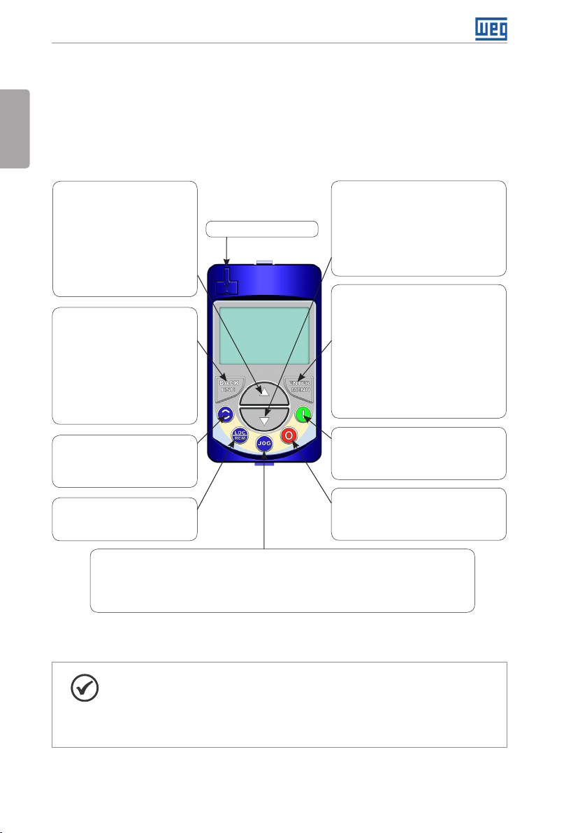
4.1 INTEGRAL KEYPAD - HMI-CFW701
English
The integral keypad can be used to operate and program (view / edit all parameters) of the
CFW701 inverter. There are two operation modes in the keypad: monitoring and programming.
The key functions and display indications of the keypad may change according to the operation
mode. The programming mode consists of three levels.
- When in monitoring mode: press
this key to increase the speed.
- When in programming mode, level
1: press this key to go back to the
previous group.
- When in programming mode, level
2: press this key to go to the next
parameter.
- When in programming mode, level
3: press this key to increase the
parameter value.
- When in programming mode, level
1: press this key to go back to the
monitoring mode.
- When in programming mode, level
2: press this key to go back to the
le ve l 1.
- When in programming mode, level
3: press this key to cancel the new
value (the value will not be saved)
and it will return to level 2 of the
programming mode.
- Press this key to define the motor
rotation.
This option is active when:
P0223 = 2 or 3 in LOC and/or
P0226 = 2 or 3 in REM.
- Press this key to change between
LOCAL and REMOTE mode.
This option is active when:
P0220 = 2 or 3.
- Press this key to accelerate the motor up to the speed set in P0122. The motor speed is maintained
while the key is pressed. When the key is released the motor decelerates up to its complete stop.
This function is active when all the following conditions are met:
1. Start/Stop = Stop.
2. General Enable = Active.
3. P0225 = 1 in LOC and/or P0228 = 1 in REM.
(1) Available from the serial number 1023801859.
USB communication port
(1)
Figure 4.1: Operator keys
- When in monitoring mode: press this key
to decrease the speed.
- When in programming mode, level 1: press
this key to go to the next group.
- When in programming mode, level 2:
press this key to go back to the previous
parameter.
- When in programming mode, level 3: press
this key to decrease the parameter value.
- When in monitoring mode: press this key
to enter in the programming mode.
- When in programming mode, level 1: press
this key to select the desired parameter
group – it shows the parameters of the
selected group.
- When in programming mode, level 2: press
this key to show the parameter – it shows
the parameter value for its modification.
- When in programming mode, level 3: press
this key to save the new parameter value
– it returns to level 2 of the programming
mode.
- Press this key to accelerate the motor
according to the acceleration ramp time.
This option is active when:
P0224 = 0 in LOC and/or
P0227 = 0 in REM.
- Press this key to decelerate the motor
according to the deceleration ramp time.
This option is active when:
P0224 = 0 in LOC and/or
P0227 = 0 in REM.
24 | CFW701
NOTE!
It is necessary to set the password at P0000 for parameter modification;
otherwise the parameters contents can only be viewed.
The default password for P0000 is 5. It is possible to change the password at
P0200. Refer to the CFW701 programming manual.
Page 30
Motor rotation
Local/Remote
(commands and
references source)
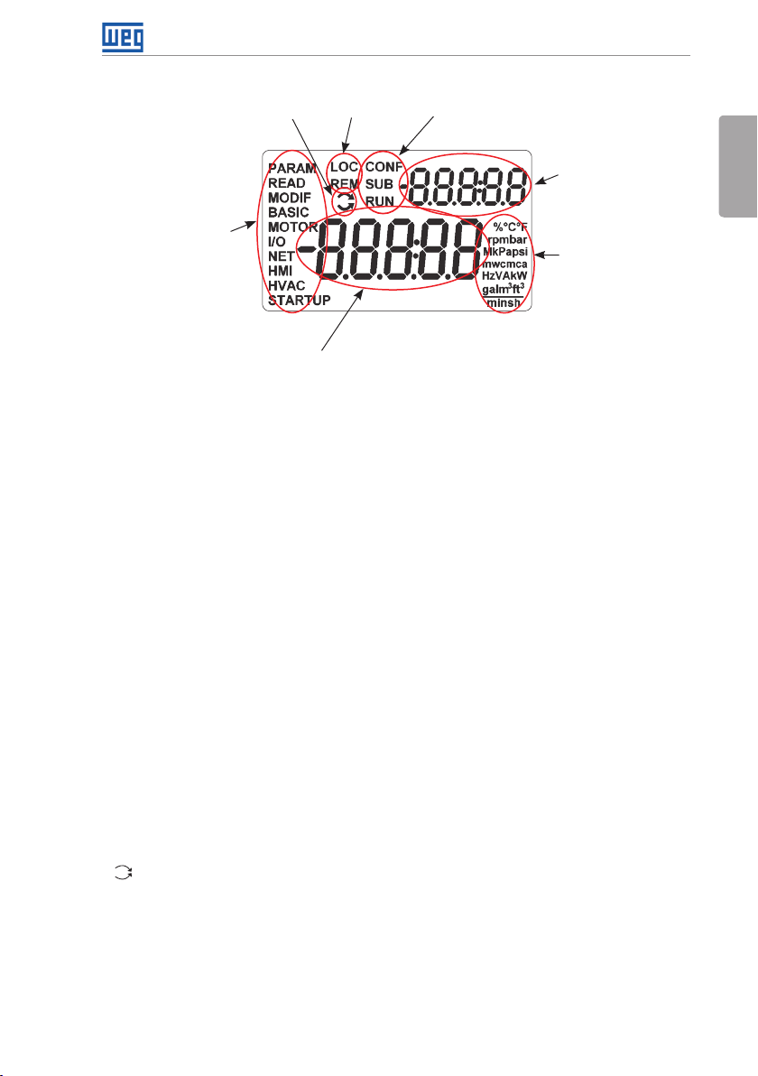
Keypad (HMI) and Basic Programming
Inverter status
Menu (parameters
group selection) –
only one parameter
group is shown at
each time.
Main display
Figure 4.2: Display sections
Parameter groups available at the Menu:
PARAM: all parameters.
READ: only the reading parameters.
MODIF: only the parameters changed compared to the factory default.
BASIC: basic application parameters.
MOTOR: parameters related to motor data control.
I/O: parameters related to the digital and analog inputs/outputs.
NET: parameters related to the communication protocol.
HMI: parameters for the keypad configuration.
Secondary display
English
Variable unit
(shows the value of
the main display)
HVAC: parameters related to HVAC application.
STARTUP: parameters for the oriented startup.
Inverter status:
LOC: local reference.
REM: remote reference.
: motor rotation according to the arrows.
CONF: configuration. It indicates that the inverter is in the Oriented Start-up routine or with
incompatible parameter programming. Refer section Incompatibility Between Parameters in
the programming manual of the CFW701.
SUB: DC link undervoltage.
RUN: inverter enabled and/or DC braking activated.
CFW701 | 25
Page 31

Keypad (HMI) and Basic Programming
English
Monitoring Mode
It is the initial state of the keypad after power up and startup screen,
with the factory default values.
The Menu is not active in this mode.
Main display and secondary display show the values of the parameters
defined at P0205 and P0206.
From the monitoring mode, pressing the ENTER/MENU key will switch
to the programming mode.
Programming Mode
Level 1:
This is the first level of the programming mode. It is possible to chose
the parameter group by using the and keys.
The main display, secondary display and variable unit are not shown
at this level.
Press the ENTER/MENU key to go to the level 2 of programming mode
- parameters selection.
Press the BACK/ESC key to go back to the monitoring mode.
Level 2:
The parameter number is displayed on the main display and its value
on the secondary display.
Use the and keys to find the desired parameter.
Press the ENTER/MENU key to go to level 3 of the programming mode
– parameters value changing.
Press the BACK/ESC key to return to level 1 of the programming mode.
Level 3:
The parameter values is shown at the main display and the parameter
number at the secondary display.
Us e the and keys to ch ange the value of th e selected para meter.
Press ENTER/MEN U key to confirm the mod ification (save th e new value)
or BACK/ESC key to cancel the modific ation (do not save the new va lue).
In both cas es, the keypad retur ns to the level 2 of the prog ramming mode.
Figure 4.3: Keypad operation modes
The keypad can be installed or removed from the inverter with or without AC power applied
to the inverter.
The HMI supplied with the product can also be used for remote command of the inverter. In
this case, use a cable with male and female D-Sub9 (DB-9) connectors wired pin to pin (mouse
extension type) or a market standard Null-Modem cable. Maximum length of 10 m (33 ft). It is
recommended the use of the M3 x 5.8 standoffs supplied with the product. Recommended
torque: 0.5 N.m (4.5 lbf.in).
Use the keypad frame accessory to assembly the keypad on the panel door or control table
(see section 7.2 ACCESSORIES on page 37, or perform the drilling as shown in Figure A.5
on page 141).
NOTE!
A list of parameters is supplied with the product, for additional information on
each parameter refer to the CFW701 programming manual provided in the
CD-ROM that accompanies the product or it can be downloaded at the WEG
homepage - www.weg.net.
26 | CFW701
Page 32

First Time Power-Up and Start-Up
5 FIRST TIME POWER-UP AND START-UP
5.1 PREPARE FOR START-UP
The inverter shall have been already installed according to the recommendations listed in
chapter 3 INSTALLATION AND CONNECTION on page 9.
DANGER!
Always disconnect the main power supply before performing any inverter
connection.
DANGER!
Débranchez toujours l'alimentation principale avant d'effectuer une connexion
sur le variateur.
1. Check if power, grounding, and control connections are correct and firmly secured.
2. Remove from the inside of the inverter all installation material left behind.
3. Verify the motor connections and if the motor voltage and current is within the rated value
of the inverter.
4. Mechanically uncouple the motor from the load: If the motor cannot be uncoupled, make
sure that the chosen direction of rotation (forward or reverse) will not result in personnel
injury and/or equipment damage.
English
5. Return the inverter covers.
6. Measure the power supply voltage and verify if it is within the range listed in chapter 8
TECHNICAL SPECIFICATIONS on page 39.
7. Apply power to the input: Close the input disconnect switch.
8. Check the result of the first time power-up: The display should show the monitoring mode
and the status LED should light and stay lit in green.
5.2 START-UP
The start-up procedure for the V/f is described in three simple steps by using the STARTUP
and BASIC group.
Steps:
1. Set the password for parameter modification.
2. Execute the Oriented Start-up routine (STARTUP group).
3. Set the parameters of the Basic Application group (BASIC).
CFW701 | 27
Page 33

First Time Power-Up and Start-Up
5.2.1 Oriented Start-up Menu
Step Action/Display Indication Step Action/Display Indication
English
1
Monitoring mode.
Press the ENTER/MENU key to get into
the first level of the programming mode.
3 4
Press ENTER/MENU when the group is
selected.
5 6
Change the parameter P0317 to “1 – Yes”,
by using the key.
7 8
In this moment the Oriented Start-up
routine is initiated and the “CONF” status
is indicated at the keypad (HMI).
The parameter “P0000 - Access to
Parameters” is selected. Change the
password to set the remaining parameters
if necessary. The factor y default is 5.
Press the key to the next parameter.
2
The PARAM group is selected, press the
or keys to select the S TART UP
group.
The parameter “P0 317 – Oriented Start-up”
is then se lected, press t he ENTER/MENU to
get into the parameter content.
Press ENTER/MENU to save.
If n ecessary, change “P029 6 – Line Rated
Voltage”. This change will affect P0151,
P0153, P0185, P0321, P0322, P0323
and P0400.
Press the key to the next parameter.
9 10
If necessary, change “P0298 – Application”
parameter. This change will affect P0156,
P0157, P0158, P0401, P0404 and P0410
(this last one only if P0202 = 0, 1 or 2 - V/f
modes). The time and level of the IGBT
overload protection will also be affected.
Press the key to the next parameter.
28 | CFW701
If necessary, change “P0202 – Control
Typ e” parameter. This guide will only show
the sett ing for P0202 = 0 (V/f 60 Hz) o r P0202
= 1 (V/f 50 Hz). Refer to the programming
manual for other settings (V/f Adjustable,
VV W or Vector Modes).
Press the key to the next parameter.
Page 34

First Time Power-Up and Start-Up
Step Action/Display Indication Step Action/Display Indication
11 12
If necessary, change “P0398 – Motor
Service Factor” parameter. This change
will affect the current and the time of the
motor overload protection operation.
Press the key to the next parameter.
13
If necessary, change “P0401 – Motor
Rated Current” parameter. This change
will af fect P0156, P0157, P0158 and P0410.
Press the key to the next parameter.
15
If necessary, change “P0403 – Motor
Rated Frequency” parameter. This
change will affect P0402.
Press the key to the next parameter.
English
If necessary, change “P0400 – Motor
Rated Voltage” parameter. This change
corrects the output voltage by the factor
“x = P0400/P0296”.
Press the key to the next parameter.
14
If necessary, change “P0404 – Motor
Rated Power” parameter. This change
will affect P0410.
Press the key to the next parameter.
16
If necessary, change “P0402 – Motor
Rated Speed”. This change will affect
P0122 to P0131, P0133, P0134, P0135,
P0182, P0208, P0288 and P0289.
Press the key to the next parameter.
17
This parameter will only be visible if
P0202 = 3 or 4.
If necessary, change “P0406 – Motor
Ventilation” parameter.
Press the key to the next parameter.
The parameters to come after selecting
P0406 may vary according to the type of
control set at P0202.
19
If necessary, change “P0408 – Run Self-
Tuning” parameter.
Press the key to the next parameter.
Run the self-tuning when running in V VW
and sensorless.
If necessary, change “P0407 - Motor
18
Rated Power Factor” parameter.
Press the key to the next parameter.
20
Press the BACK/ESC key to end the
Oriented Start-up routine.
Press the BACK/ESC again to go back to
the monitoring mode.
Figure 5.1: Oriented start-up
CFW701 | 29
Page 35

First Time Power-Up and Start-Up
5.2.2 Basic Application Menu
Step Action/Display Indication Step Action/Display Indication
English
1
Monitoring mode.
Press the ENTER/MENU key to get into
the first level of the programming mode.
3 4
Press ENTER/MENU when the group is
selected.
5 6
If necessary, change “P0101 – Deceleration
Time”.
Press the or key to the next
parameter.
2
The PARAM group is selected, press the
or keys to sele ct the BASIC group.
In this moment the Basic Application
routine is initiated. If necessar y, change
“P0100 – Acceleration Time” parameter.
Press the or key to the next
parameter.
If necessary, change “P0133 – Minimum
Speed” parameter.
Press the or key to the next
parameter.
7 8
If necessary, change “P0134 – Maximum
Speed” parameter.
Press the or key to the next
parameter.
9 10
If necessary, change “P0136 – Manual
Torque Boost” parameter.
Press the or key to the next
parameter.
Figure 5.2: Basic application group
30 | CFW701
If necessary, change “P0135 – Max.
Output Current” parameter.
Press the or key to the next
parameter.
Press the BACK/ESC key to end the Basic
Application routine.
Press the BACK/ESC again to go back to
the monitoring mode.
Page 36

Troubleshooting and Maintenance
6 TROUBLESHOOTING AND MAINTENANCE
6.1 FAULTS AND ALARMS
NOTE!
Refer to the CFW701 quick reference guide and the programming manual for
more information about the errors and alarms.
6.2 SOLUTIONS FOR THE MOST FREQUENT PROBLEMS
Table 6.1: Solutions for the most frequent problems
Problem
Motor does not start Incorrect wiring
Motor speed
fluctuates (oscillates)
Motor speed too
high or too low
Motor does not
reach the rated
speed, or motor
speed starts
oscillating around
the rated speed
(Vector Control)
Point to be
Verified
connection
Analog reference
(if used)
Incorrect settings 1. Check if parameters are properly set for the application.
Fault 1. Check if the inverter is not blocked due to a fault condition.
Motor stall 1. Decrease motor overload.
Loose connection 1. Stop the inverter, turn off the power supply, and check
Defective reference
potentiometer
Oscillation of the
external analog
reference
Incorrect settings
(vector control)
Incorrect settings
(reference limits)
Control signal
from the analog
reference (if used)
Motor nameplate 1. Check if the motor has been properly sized for the
Settings 1. Decrease P0180.
1. Check all power and control connections.
1. Check if the external signal is properly connected.
2. Check the status of the control potentiometer (if used).
2. Check if terminals XC1:15 and 16 and/or XC1:34 and 36
are not shorted (short-circuit at the 24 Vdc power supply).
2. Increase P0136, P0137 (V/f), or P0169/P0170 (vector
control).
and tighten all power connections.
2. Check all internal connections of the inverter.
1. Replace potentiometer.
1. Identify the cause of the oscillation. If it is caused by
electrical noise, use shielded cables or separate from the
power and control wiring.
1. Check parameters P0410, P0412, P0161, P0162, P0175,
and P0176.
2. Refer to the programming manual.
1. Check if the values of P0133 (Minimum Speed) and
P0134 (Maximum Speed) are properly set for the motor
and application used.
1. Check the level of the reference control signal.
2. Check the settings (gain and offset) of parameters P0232
to P0240.
application.
2. Check P0410.
Corrective Action
English
CFW701 | 31
Page 37

Troubleshooting and Maintenance
Problem
Off display Keypad
English
Motor does not
operate in the field
weakning region
(Vector Control)
Point to be
Verified
connections
Power supply
voltage
Mains supply fuses
open
Settings 1. Decrease P0180.
1. Check the inverter keypad connection.
1. Rated values shall be within the limits specified below:
200...240 V power supply: (Frame sizes A to D) Minimum:
170 V; Maximum: 264 V.
220 / 230 V power supply: (Frame size E) Minimum: 187 V;
Maximum: 253 V.
380...480 V power supply: Minimum: 323 V;
Maximum: 528 V.
500...600 V power supply: Minimum: 425 V;
Maximum: 660 V.
1. Replace fuses.
Corrective Action
6.3 INFORMATION FOR CONTACTING TECHNICAL SUPPORT
For technical support and servicing, it is important to have the following information in hand:
Inverter model.
Serial number and manufacturing date available on the identification label of the product (refer
to section 2.5 IDENTIFICATION LABELS on page 7 and the Figure A.2 on page 139).
Installed software version (check parameter P0023).
Application data and inverter settings.
6.4 PREVENTIVE MAINTENANCE
DANGER!
Always turn off the mains power supply before touching any electrical
component associated to the inverter.
High voltage may still be present even after disconnecting the power supply.
To prevent electric shock, wait at least 10 minutes after turning off the input
power for the complete discharge of the power capacitors.
Always connect the equipment frame to the protective ground (PE). Use the
adequate connection terminal at the inverter.
32 | CFW701
Page 38

Troubleshooting and Maintenance
DANGER!
Débranchez toujours l'alimentation principale avant d'entrer en contact avec
un appareil électrique associé au variateur.
Des tensions élevées peuvent encore être présentes, même après déconnexion
de l’alimentation.
Pour éviter les risques d’électrocution, attendre au moins 10 minutes après
avoir coupé l’alimentation
d’entrée pour que les condensateurs de puissance soient totalement
déchargées.
Raccordez toujours la masse de l'appareil à une terre protectrice (PE). Utiliser
la borne de connexion adéquate du variateur.
ATTENTION!
The electronic boards have electrostatic discharge sensitive components.
Do not touch the components or connectors directly. If necessary, first touch
the grounded metallic frame or wear a ground strap.
English
Do not perform any withstand voltage test!
If necessary, consult WEG.
The inverters require low maintenance when properly installed and operated. The Table 6.2 on
page 33 presents the main procedures and time intervals for preventive maintenance. The
Table 6.3 on page 34 provides recommended periodic inspections to be performed every
6 months after the inverter start-up.
Table 6.2: Preventive maintenance
Maintenance Interval Instructions
Replacement procedure showed in
Fan replacement After 50.000 hours of operation.
If the inver ter
is stocked
(not being
Electrolytic
capacitors
(1) The inver ters are set at the factory for automatic fan control (P0352 = 2), which means that they will be turned on only
when the heatsink temperature exceeds a reference value. Therefore, the operating hours of the fan will depend on the
inverter usage conditions (motor current, output frequency, cooling air temperature, etc.). The inver ter stores the number
of fan operating hours in the parameter P0045. When this parameter reaches 50000 operating hours, the keypad display
shows the alarm A0177.
used):
“Reforming”
Inverter is
being used:
replace
Every year from the
manufacturing date printed on
the inverter identification label
(refer to the chapter 2 GENERAL
INSTRUCTIONS on page 3).
Every 10 years.
(1)
Figure 6.1 on page 35 and Figure
6.2 on page 35.
Apply power to the inverter (voltage
between 220 and 230 Vac, singlephase or three-phase, 50 or 60 Hz) for
at least one hour. Then, disconnect
the power supply and wait at least
24 hours before using the inverter
(reapply power).
Contact WEG technical support to
obtain replacement procedure.
CFW701 | 33
Page 39

Troubleshooting and Maintenance
Table 6.3: Recommended periodic inspections - Every 6 months
Component Abnormality Corrective Action
English
Terminals, connectors
Fans /Cooling systems
Printed circuit boards
Power module/ Power
connections
Capacitors of the DC
link (Intermediate Circuit)
Power resistors
Heatsink
Loose screws
Loose connectors
Dirty fans Cleaning
Abnormal acoustic noise
Blocked fan
Abnormal vibration
Dust in the panel air filters Cleaning or replacement
Accumulation of dust, oil, humidity, etc. Cleaning
Odor Replacement
Accumulation of dust, oil, humidity, etc. Cleaning
Loose connection screws Tightening
Discoloration/ odor / electrolyte leakage
Safety valve expanded or broken
Frame expansion
Discoloration
Odor
Accumulation of dust
Dirt
6.5 CLEANING INSTRUCTIONS
When it is necessary to clean the inverter, follow the instructions below:
Ventilation system:
Tighten
Replace the fan. Refer to the
Figure 6.1 on page 35 and
Figure 6.2 on page 35.
Check the fan connections.
Replacement
Replacement
Cleaning
Disconnect the inverter power supply and wait at least 10 minutes.
Remove the dust from the cooling air inlet by using a soft brush or a flannel.
Remove the dust from the heatsink fins and from the fan blades by using compressed air.
Electronic boards:
Disconnect the inverter power supply and wait at least 10 minutes.
Remove the dust from the electronic board by using an anti-static brush or an ion air gun
(Charge Buster Ion Gun - reference A6030-6DESCO).
If necessary, remove the boards from the inverter.
Always wear a ground strap.
34 | CFW701
Page 40

Troubleshooting and Maintenance
1 2 3
English
Releasing the latches of the
fan cover
1 2 3
Fan grill screws removal Fan removal
(b) Models 142 A, 180 A and 211 A
Figure 6.1: (a) and (b) Fan removal
1 2
Cable connection Fan fitting
Fan removal
(a) Models up to 105 A
(a) Models up to 105 A
Cable disconnection
Cable disconnection
1 2
Cable connection Fan and grill fastening
(b) Models 142 A, 180 A and 211 A
Figure 6.2: (a) and (b) Fan installation
CFW701 | 35
Page 41

Option Kits and Accessories
7 OPTION KITS AND ACCESSORIES
7.1 OPTION KITS
English
Some models cannot incorporate all available option kits. Refer to Table 2.2 on page 6 for
a detailed description of the option kits that are available for each inverter model.
7.1.1 Dynamic Braking IGBT (only for frame size E and 500...600 V models of frame size D) - CFW701E...DB...
Refer to item 3.2.3.2 Dynamic Braking (standard built-in for frame sizes A, B, C and D and
optional built-in for frame size E - CFW701...DB...) on page 15, for more details about the
Dynamic Braking.
7.1. 2 Nema1 Protection Degree (only for frame sizes A, B, C and E and
500...600 V models of frame size D) - CFW701...N1...
Inverter with Nema1 enclosure. Refer to Figure B.2 on page 169. These inverters have the
KN1X-02 kit (refer to section 7.2 ACCESSORIES on page 37).
7.1. 3 IP55 Protection Degree (only for frame sizes B and C) - CFW701...N12...
Inverter with IP55 enclosure. Refer to Figure A.10 on page 146. These inverters have the
PCSC-03 kit (refer to section 7.2 ACCESSORIES on page 37).
7.1.4 IP21 Protection Degree (only for frame sizes A, B and C) - CFW701...21...
Inverter with IP21 enclosure. Refer to Figure A.9 on page 145. These inverters have the
KIP21X-01 kit (refer to section 7.2 ACCESSORIES on page 37).
7.1. 5 STO Function - CFW701...Y1...
The STO function complies with the requirements of category 3 (PL d) according to EN ISO
13849-1, SIL CL 2 according to IEC 61800-5-2 / IEC 62061 / IEC 61508 and can be used in
applications up to category 3 (PL d) according to EN ISO 13849-1 and SIL 2 according to IEC
62061 / IEC 61508. Refer to the guide or the CD ROM supplied with the product for more
information.
NOTE!
It is not possible to assemble the top cover on inverters of frame size A that
have optional safety stop. Thus, it is not possible to raise the protection level
of these inverters to IP21 or Nema1.
STO function is incompatible with fire mode and bypass functionalities.
7.1.6 24 Vdc External Control Power Supply - CFW701...W1...
The use of this option kit is recommended with communication networks (Profibus, DeviceNet,
etc.), since the control circuit and the network communication interface are kept active (with
power supply and responding to the network communication commands) even in the event of
main power supply interruption.
Inverters with this option have a built-in DC/DC converter with a 24 Vdc input that provides
36 | CFW701
Page 42

Option Kits and Accessories
adequate outputs for the control circuit. Therefore, the control circuit power supply will be
redundant, i.e., it can be provided either by a 24 Vdc external power supply (connection as
shown in Figure 7.1 on page 37) or by the standard internal switched mode power supply
of the inverter.
Observe that the inverters with the external 24 Vdc power supply option use terminals XC1:34
and 36 or XC1:15 and 16 as the input for the external power supply and no longer as the output
like in the standard inverter (Figure 7.1 on page 37).
In case of interruption of the external 24 Vdc power supply, the digital inputs/outputs will no
longer be fed, even if the mains power is on. Therefore, it is recommended to keep the 24 Vdc
power supply always connected to the terminals XC1:34 and 36 or XC1:15 and 16.
24 Vcc
± 10 %
@ 1.5 A
24 Vcc
± 10 %
@ 1.5 A
a) Connection terminals for
XC1:34 and 36
Figure 7.1: External 24 Vdc power supply capacity and connection terminals
b) Connection terminals for
XC1:15 and 16
English
7.2 ACCESSORIES
The accessories are installed to the inverter easily and quickly using the “Plug and Play” concept.
When an accessory is connected to the slots, the control circuit automatically identifies the
model of this accessory and its code is presented in the parameter P0028. The accessory shall
be installed with the inverter power supply off.
The code and model of each available accessory is presented in the Table 7.1 on page 38.
The accessories can be ordered individually and they will be provided in their own packaging
containing the components and guides with detailed instructions for installation, operation and
programming.
CFW701 | 37
Page 43

Option Kits and Accessories
Table 7.1: Accessory models
WEG Part
Number
English
Name Description Slot
Control Accessories
11511 5 5 8 USB-RS-485/RS-422 USB-RS-485/RS-422 Interface kit. - -
Flash Memory Module
113 5 5 9 8 0 MMF-02 FLASH memory module. 5 --xx
Expansion Module
114020 3 8 CCK-01 Output relays module. - -
11829628 HMI-03 CFW701 stand-alone keypad (HMI).
Stand-alone Keypad, Blank Cover, and Frame for Remote Mounted Keypad
(2)
11829782 RHMIF-03 Remote keypad frame kit (IP56). - 10950192 1 m HMI CAB-RS _1M 1 m serial remote keypad cable set. - 10951226 2 m HMI CAB-RS _2M 2 m serial remote keypad cable set. - 10951223 3 m HMI CAB-RS _3M 3 m serial remote keypad cable set. - 10951227 5 m HMI CAB-RS _5M 5 m serial remote keypad cable set. - 10951240 7.5 m HMI CAB-RS _7.5M 7.5 m serial remote keypad cable set. - 10951239 10 m HMI CAB-RS _10M 10 m serial remote keypad cable set. - 11010298 HMID-01 Blank cover for the keypad slot. HMI -
11401877 KN1A- 02 Nema1 kit for frame size A inverter.
Miscellaneous
11401938 K N1B-02 Nema1 kit for frame size B inverter.
114018 5 7 KN1C- 02 Nema1 kit for frame size C inverter.
10960842 KN1E-01
10960850 KN1E-02
Nema1 kit for models 105 A and 142 A of
frame size E inverter.
Nema1 kit for models 180 and 211 A of frame
size E inverter.
(3)
(3)
(3)
(3)
(3)
114019 3 9 KIP 21A-01 IP21 kit for frame size A inverter. - 114019 41 KIP21B-01 IP21 kit for frame size B inverter. - 11401940 KIP21C-01 IP21 kit for frame size C inverter. - 11010264 KI P21D-01 IP21 kit for frame size D inverter. - 11010265 PCSA-01 Kit for power cables shielding - frame size A. - 11010266 PCSB-01 Kit for power cables shielding - frame size B. - 11010267 PCSC-01 Kit for power cables shielding - frame size C. - -
11119781 PCSD-01
10960844 PCSE-01
1270 5234 PCSC-03
10960847 CCS-01
Kit for power cables shielding - frame size D
(included in the standard product).
Kit for power cables shielding - frame size E
(included in the standard product).
Kit for power cables shielding - frame sizes B
and C with degree of protection IP55.
Kit for control cables shielding (included in
the standard product).
CFW701 Control Rack (includes the CC701.
11829630 CONRA-03
CDE control board and it is supplied with the
product).
10790788 DBW030380D3848SZ 380...480 Vac dynamic braking module. - 10794631 DBW030250D5069SZ 500...690 Vac dynamic braking module. - -
Notes:
(1) The identific ation of the MMF-0 2 module is pres ented in the bit 6 of th e parameter P0028. Refer to C FW701 programm ing
manual.
(2) Use DB-9 pin, male-to-female, straight-through cable (serial mouse extension type) for connecting the keypad to the
inverter or Null-Modem standard cable. Ma ximum cable length: 10 m (33 f t).
Examples:
- Mouse ex tension cable - 1.80 m (6 ft); Manufacturer: Clone.
- Belkin pro series DB9 serial extension cable 5 m (17 ft); Manufacturer: Belkin.
- Cables Unlimited PCM195006 cable, 6 ft DB9 m/f; Manufacturer: Cables Unlimited.
(3) Refer to Figure B.2 on page 169.
38 | CFW701
Identification
Parameters
- P0028
(1)
HMI -
- -
- -
- -
- -
- -
- -
- -
- -
- -
- -
Page 44

8 TECHNICAL SPECIFICATIONS
8.1 POWER DATA
Power Supply:
Technical Specifications
Maximum rated voltage: 240 V for 200...240 V models, 230 V for 220 / 230 V models and
480 V for 380...480 V models and 600 V for 500...600 models up to 2000 m height. It is
necessary to apply 1.1 % voltage derating every 100 m (328 ft) above 2000 m (6562 ft),
limited to 4000 m (13123 ft).
Voltage tolerance: -15 % to +10 %.
Frequency: 50/60 Hz (48 Hz to 62 Hz).
Phase imbalance: ≤3 % of the rated phase-to-phase input voltage.
Overvoltage according to Category III (EN 61010/UL 508C).
Transient voltage according to Category III.
Maximum of 60 connections per hour (1 per minute).
Typical efficiency: ≥ 97 %.
Typical input power factor:
- 0.94 for three-phase power supply models in the rated conditions.
- 0.70 for single-phase power supply models in the rated conditions.
Displacement factor (cos ϕ): > 0.98.
Refer to APPENDIX B - TECHNICAL SPECIFICATIONS on page 148 for more information
about the technical specifications.
English
CFW701 | 39
Page 45

Technical Specifications
8.2 ELECTRICAL/GENERAL SPECIFICATIONS
Table 8.1: Electrical/general specifications
English
CONTROL METHOD Voltage source.
OUTPUT
FREQUENCY
PERFORMANCE SPEED
CONTROL
PERFORMANCE TORQUE
CONTROL
USER’S POWER
SUPPLIES
REF
(XC1:21-24)
(CC701 board)
+5 V
(XC1:1-8)
+24 V 24 V ± 10 % power supply to be used with the digital inputs/outputs.
INPUTS
ANALOG 3 differential inputs.
(CC701
board)
DI GITAL 8 isolated digital inputs.
Type of control:
- V/f (Scalar).
- VV W: Voltage Vector Control.
- Sensorless vector control (without encoder).
PWM SVM (Space Vector Modulation).
Full digital (software) current, flux, and speed regulators.
Execution rate:
- current regulators: 0.2 ms (5 kHz).
- flux regulator: 0.4 ms (2.5 kHz).
- speed regulator / speed measurement: 1.2 ms.
0 to 3.4 x rated motor frequency (P0403). The rated motor frequency
is programmable from 0 Hz to 300 Hz in the V/f and VV W modes
and from 30 Hz to 120 Hz in the vector mode.
Ma ximum output frequency limit according to the switching frequency:
- 125 Hz (switching frequency = 1.25 kHz).
- 200 Hz (Switching frequency = 2 kHz).
- 250 Hz (switching frequency = 2.5 kHz).
- 500 Hz (switching frequency ≥ 5 kHz).
V/f (Scalar):
Regulation (with slip compensation): 1 % of the rated speed.
Speed variation range: 1:20.
VVW:
Regulation: 1 % of the rated speed.
Speed variation range: 1:30.
Sensorless:
Regulation: 0.5 % of the rated speed.
Speed variation range: 1:100.
Range: 10 to 180 %, regulation: ±5 % of the rated torque (with
encoder).
Range: 20 to 180 %, regulation: ±10 % of the rated torque (sensorless
above 3 Hz).
10 V ± 10 % power supply to be used with the potentiometer at the
analog inputs.
Maximum output current: 2 mA.
5 V ± 5 % power supply.
Maximum output current: 160 mA.
Maximum output current: 500 mA.
Resolution: 11 bits + signal.
Input levels: (0 to 10) V, (-10 to 10) V, (0 to 20) mA or (4 to 20) mA.
Impedance: 400 kΩ for the voltage input, 500 Ω for the current input.
Maximum input voltage: ± 15 V.
Programmable functions.
24 Vdc (High level ≥ 10 V, Low level ≤ 2 V).
Maximum input voltage: ± 30 Vdc.
Input impedance: 2 kΩ.
Active high or active low input selectable by jumper (simultaneous
selection for all inputs).
(1)
40 | CFW701
Page 46

Technical Specifications
OUTPUTS
(CC701
board)
ANALOG 2 non isolated outputs.
Voltage (0 to 10 V) or current (0/4 mA to 20 mA) output.
Maximum load: RL ≥ 10 kΩ (voltage) or RL ≤ 500 Ω (current).
Resolution: 10 bits.
Programmable functions.
RE L AY 2 relays (NO).
Maximum voltage: 240 Vac / 30 Vdc.
Maximum current: 0.75 A.
Programmable functions.
TRANSISTOR 3 open collector isolated digital outputs (with the same reference as
the 24 V power supply).
Maximum current: 80 mA.
Maximum voltage: 30 Vdc.
Programmable functions.
(2)
SAFETY PROTECTION Output overcurrent/short-circuit.
Under/Overvoltage.
Phase loss.
Overtemperature of the heatsink/internal air.
I GBTs ove r load .
Motor overload.
External fault / alarm.
CPU or memory fault.
Output phase-ground short-circuit.
INTEGRAL
KE YPAD
(HMI)
STANDA RD
KE YPAD
9 operator keys: Start/Stop, Up arrow, Down arrow, Direction of
rotation, Jog, Local/Remote, BACK/ESC and ENTER/MENU.
LCD display.
View/edition of parameters.
Indication accuracy:
- current: 5 % of the rated current.
- speed resolution: 1 rpm.
Possibility of remote mounting.
USB communication port.
(3)
ENCLOSURE IP20 Frame sizes A, B and C inverters without the top cover and Nema1 kit.
NE M A1/ IP2 0 Frame size D inverters without IP21 kit.
Frame size E inverters without Nema1 kit.
IP21 Frame sizes A, B and C inverters with top cover.
Frame size E inverters with Nema1 kit (KN1E-01 or KN1E-02).
NE M A1/ IP21 Frame sizes A, B and C inverters with top cover and Nema1 kit.
IP55 Frame sizes B, C, D and E.
Frame size D inverters with IP21 kit.
Rear part of the inverter (external part for flange mounting).
(1) AI3 only has (0 to 20) mA and (4 to 20) mA input levels.
(2) Transistor outputs have an internal freewheel diode to +24 V
(3) Available from the serial number 1023801859.
English
CFW701 | 41
Page 47

Technical Specifications
8.2 .1 Codes and Standards
English
SAFETY
STANDA RDS
ELECTROMAGNETIC
COMPATIBILITY
(EMC)
MECHANICAL
STANDA RDS
Table 8.2: Codes and Standards
UL 508C - Power conversion equipment.
UL 840 - Insulation coordination including clearances and creepage distances
for electrical equipment.
EN61800-5-1 - Safety requirements electrical, thermal and energy.
EN 50178 - Electronic equipment for use in power installations.
EN 60204-1 - Safety of machinery. Electrical equipment of machines. Part 1:
General requirements.
Note: The final assembler of the machine is responsible for installing an safety
stop device and a supply disconnecting device.
EN 60146 (IEC 146) - Semiconductor converters.
EN 61800-2 - Adjustable speed electrica l power drive systems - Part 2: General
requirements - Rating specifications for low voltage adjustable frequency AC
power drive systems.
EN 61800-3 - Adjustable speed electrical power drive systems - Part 3: EMC
product standard including specific test methods.
EN 55011 - Limits and methods of measurement of radio disturbance
characteristics of industrial, scientific and medical (ISM) radio-frequency
equipment.
CISPR 11 - Industrial, scientific and medical (ISM) radio-frequency equipment
– Electromagnetic disturbance characteristics - Limits and methods of
measurement.
EN 61000-4-2 - Electromagnetic compatibility (EMC) - Part 4: Testing and
measurement techniques - Section 2: Electrostatic discharge immunity test.
EN 61000-4-3 - Electromagnetic compatibility (EMC) - Part 4: Testing
and measurement techniques - Section 3: Radiated, radio-frequency,
electromagnetic field immunity test.
EN 61000-4-4 - Electromagnetic compatibility (EMC) - Part 4: Testing and
measurement techniques - Section 4: Electrical fast transient/burst immunity
test.
EN 61000-4-5 - Electromagnetic compatibility (EMC) - Part 4: Testing and
measurement techniques - Section 5: Surge immunity test.
EN 61000-4-6 - Electromagnetic compatibility (EMC) - Part 4: Testing and
measurement techniques - Section 6: Immunity to conducted disturbances,
induced by radio-frequency fields.
EN 60529 - Degrees of protection provided by enclosures (IP code).
UL 50 - Enclosures for electrical equipment.
42 | CFW701
Page 48

Manual del Usuario
Serie: CFW701
Idioma: Español
Documento: 10001393824 / 02
Modelos: Tam A...E
Fecha: 05/2015
Page 49

Sumario de las Revisiones
La información a seguir describe las revisiones ocurridas en este manual.
Versión Revisión Descripción
- R00 Primera edición
- R01 Revisión general
- R02
La in cl usi ón de nue vos m od el os t am añ os D y E
Actualización de IP54 a IP55 en los tamaños B y C
¡ATENCIÓN!
Los parámetros P0296 (Tensión Nominal Red), P0400 (Tensión Nominal del
Motor) y P0403 (Frecuencia Nominal del Motor) fueran ajustados en:
modelos 200...240 V / 220 / 230 V (S2, B2 y T2): P0296 = 0 (200 / 240 V),
P0400 = 220 V y P0403 = 60 Hz.
modelos 380...480 V (T4): P0296 = 3 (440 / 460 V), P0400 = 440 V y
P0403 = 60 Hz.
modelos 500...600 V (T5): P0296 = 6 (550 / 575 V), P0400 = 575 V y
P0403 = 60 Hz.
Para valores diferentes de tensión nominal de la red y/o tensión y frecuencia
nominales del motor, ajustar estos parámetros vía menú STARTUP, conforme
presentado en la sección 5.2 PUESTA EN MARCHA en la página 75, de
ese manual.
Page 50

Índice
1 INSTRUCCIONES DE SEGURIDAD ................................................47
1.1 AVISOS DE SEGURIDAD EN EL MANUAL ............................................47
1.2 AVISOS DE SEGURIDAD EN EL PRODUCTO ....................................... 47
1.3 RECOMENDACIONES PRELIMINARES ................................................48
2 INFORMACIONES GENERALES ...................................................... 49
2.1 SOBRE EL MANUAL ...............................................................................49
2.2 SOBRE EL CFW701 .................................................................................49
2.3 NOMENCLATURA ...................................................................................52
2.4 LISTA DE LOS MODELOS DISPONIBLES .............................................54
2.5 ETIQUETAS DE IDENTIFICACIÓN DEL CFW701 .................................54
2.6 RECIBIMIENTO Y ALMACENADO .........................................................55
3 INSTALACIÓN Y CONEXIÓN ............................................................56
3.1 INSTALACIÓN MECÁNICA .....................................................................56
3.1.1 Condiciones Ambientales .............................................................56
3.1.2 Posicionamiento y Fijación ..........................................................56
3.2 INSTALACIÓN ELÉCTRICA ....................................................................57
3.2.1 Identificación de los Bornes de Potencia y Puntos de
Puesta a Tierra ........................................................................................58
3.2.2 Cableado de Potencia, Puesta a Tierra y Fusibles ...................60
3.2.3 Conexiones de Potencia...............................................................61
3.2.3.1 Conexiones de Entrada .................................................... 61
3.2.3.2 Frenado Reostático (incluído en el producto estándar
para los tamaños A, B, C y D y opcional para el tamaño E -
CFW701...DB...) ..............................................................................62
3.2.3.3 Conexiones de Salida .......................................................63
3.2.4 Conexiones de Puesta a Tierra ...................................................65
3.2.5 Conexiones de Control .................................................................65
3.2.6 Distancia para Separación de Cables ........................................69
3.3 INSTALACIONES DE ACUERDO CON LA DIRECTIVA EUROPEA
DE COMPATIBILIDAD ELECTROMAGNÉTICA ...........................................69
3.3.1 Instalación Conforme ....................................................................69
3.3.2 Niveles de Emisión y Inmunidad Cumplidos .............................70
Español
4 HMI Y PROGRAMACIÓN BÁSICA ....................................................71
4.1 INTERFAZ HOMBRE MÁQUINA HMI -CFW701 ....................................71
5 ENERGIZACIÓN Y PUESTA EN MARCHA ......................................75
5.1 PREPARACIÓN Y ENERGIZACIÓN ........................................................75
5.2 PUESTA EN MARCHA .............................................................................75
5.2.1 Menú STARTUP - Start-up Orientado .........................................76
5.2.2 Menú BASIC - Aplicación Básica ................................................ 78
6 DIAGNÓSTICO DE PROBLEMAS Y MANTENIMIENTO .................79
6.1 FALLAS Y ALARMAS ............................................................................... 79
6.2 SOLUCIONES DE LOS PROBLEMAS MÁS FRECUENTES .................79
6.3 DATOS PARA CONTACTAR CON LA ASISTENCIA TÉCNICA .............80
6.4 MANTENIMIENTO PREVENTIVO ...........................................................80
6.5 INSTRUCCIONES DE LIMPIEZA ...........................................................82
Page 51

Índice
7 OPCIONALES Y ACCESORIOS ........................................................84
7.1 OPCIONALES ...........................................................................................84
7.1.1 IGBT de Frenado Reostático (solamente tamaño E y
modelos 500...600 V del tamaño D) - CFW701E...DB... ......................84
7.1.2 Grado de Protección Nema1 (solamente tamaños A, B, C, E y
modelos 500...600 V del tamaño D) - CFW701...N1... .........................84
7.1.3 Grado de Protección IP55 (solamente tamaños B y C) –
CFW701…N12… ......................................................................................84
7.1.4 Grado de Protección IP21 (solamente A, B y C) -
CFW701...21... ..........................................................................................84
7.1.5 Función STO - CFW701...Y1... ........................................................84
7.1.6 Alimentación Externa del Control en 24 Vcc - CFW701...W1... .84
7.2 ACCESORIOS ...........................................................................................85
8 ESPECIFICACIONES TÉCNICAS .....................................................87
8.1 DATOS DE POTENCIA .............................................................................87
8.2 DATOS DE LA ELECTRÓNICA/GENERALES .......................................88
8.2.1 Normativas Atendidas ..................................................................90
ANEXO A - DIAGRAMAS Y FIGURAS .............................................. 138
ANEXO B - ESPECIFICACIONES TÉCNICAS ..................................148
Español
Page 52

Instrucciones de Seguridad
1 INSTRUCCIONES DE SEGURIDAD
Este manual contiene las informaciones necesarias para el uso correcto del convertidor de
frecuencia CFW701.
Este manual fue desarrollado para que sea utilizado por personas con entrenamiento o
calificación técnica adecuados para operar este tipo de equipamiento. Estas personas deben
seguir las instrucciones de seguridad definidas por normas locales. No seguir las instrucciones
de seguridad puede resultar en riesgo de muerte y/o daños al equipamiento.
1.1 AVISOS DE SEGURIDAD EN EL MANUAL
¡PELIGRO!
Los procedimientos recomendados en este aviso tienen como objetivo proteger
al usuario contra muerte, heridas graves y daños materiales considerables.
¡ATENCIÓN!
Los procedimientos recomendados en este aviso tienen como objetivo evitar
daños materiales.
¡NOTA!
Las informaciones mencionadas en este aviso son importantes para el correcto
entendimiento y el buen funcionamiento de producto
Español
1.2 AVISOS DE SEGURIDAD EN EL PRODUCTO
Los siguientes símbolos están fijados al producto, sirviendo como aviso de seguridad:
Tensiones elevadas presentes.
Componentes sensibles a descargas electrostáticas.
No tocarlos.
Conexión obligatoria de puesta a tierra de protección (PE).
Conexión del blindaje al tierra.
Superficie caliente.
CFW701 | 47
Page 53

Instrucciones de Seguridad
1.3 RECOMENDACIONES PRELIMINARES
¡PELIGRO!
Siempre desconecte la alimentación general antes de tocar en cualquiera
componente eléctrico asociado al convertidor de frecuencia. Muchos
componentes pueden permanecer cargados con alta tensión y/o en movimiento
(ventiladores), mismo después que la alimentación CA de entrada fuera
desconectado o desligado. Aguarde por lo menos 10 minutos para garantizar la
total descarga de los capacitores. Siempre conecte la carcasa del equipamiento
a tierra de protección (PE) en el punto adecuado para eso.
¡NOTA!
Convertidores de frecuencia pueden interferir en otros equipamientos
electrónicos. Siga los cuidados recomendados en el capítulo 3 INSTALACIÓN
Y CONEXIÓN en la página 56, para minimizar estos efectos.
Leer completamente este manual antes de instalar u operar este convertidor
de frecuencia.
¡No ejecute ninguno ensayo de tensión aplicada en el convertidor de frecuencia!
Caso sea necesario consulte la WEG.
Español
48 | CFW701
Page 54

Informaciones Generales
2 INFORMACIONES GENERALES
2.1 SOBRE EL MANUAL
Este manual presenta informaciones para la adecuada instalación y operación del convertidor,
colocación en funcionamento en el modo de control V/f (escalar), las principales características
técnicas y como identificar y corregir los problemas más comunes de los diversos modelos de
convertidores de la línea CFW701.
¡ATENCIÓN!
La operación de este equipamiento requiere instrucciones de instalación y
operación detalladas, suministradas en el manual del usuario, manual de
programación y manuales de comunicación. El manual del usuario y la referencia
rápida de los parámetros son suministrados impresos en la adquisición del
convertidor, ya los guías son suministrados impresos junto con su respectivo
accesorio, los demás manuales son suministrados apenas en formato
electrónico en el CD-ROM que acompaña el convertidor o pueden ser obtenidos
en el sitio de la WEG - www.weg.net. El CD deberá siempre mantenerse con
este equipamiento. Una copia impresa de los archivos disponibilizados en el
CD puede solicitarse por medio de su representante local WEG.
Parte de las figuras y tablas están disponibilizadas en los anexos, los cuales están divididos
en ANEXO A - DIAGRAMAS Y FIGURAS en la página 138 para figuras y ANEXO B -
ESPECIFICACIONES TÉCNICAS en la página 148 para especificaciones técnicas. Las
informaciones están en tres idiomas.
Para más informaciones, consultar la documentación técnica:
Manual de Programación CFW701.
Manual del Usuario Modbus.
Manual del Usuario BACnet.
2.2 SOBRE EL CFW701
El convertidor de frecuencia CFW701 es un producto de alto desempeño que permite el control
de velocidad y del torque (par) de motores de inducción trifásicos. La característica central de
este producto es la tecnologia “Vectrue”, la cual presenta las siguientes ventajas:
Control escalar (V/f), VV W o control vectorial programables en el mismo producto.
El control vectorial puede ser programado como “sensorles” (lo que significa motores
padrones, sin necesidad de encoder).
El control vectorial “sensorles” permite alto torque (par) y rapidez en la respuesta, mismo en
velocidades muy bajas o en el arranque.
Función “Frenado Optimo” para el control vectorial, permitiendo el frenado controlado del
motor, eliminando en algunas aplicaciones la resistencia de frenado adicional.
CFW701 | 49
Español
Page 55

Informaciones Generales
Función “Autoajuste” para el control vectorial, permitiendo el ajuste automático de los
reguladores y parámetros de control, a partir de la identificación (también automática) de los
parámetros del motor y de la carga utilizada.
Los principales componentes del CFW701 pueden ser verificados en la Figura A.1 en la página
138.
Español
50 | CFW701
Page 56

Filtro RFI C3
Informaciones Generales
= Conexión del barramiento CC
= Conexión para el
DC+ DC-BR
(*)
resistor de frenado
Red de
alimentación
PC
Software WPS
Software WLP
(remota)
HMI
Entradas
digitales
DI1 a DI8
Entradas
analógicas
AI1 a AI3
R/L1/L
S/L2/N
T/L 3
PE
RS-485
Retificador
trifásico
Precarga
Link CC
Banco de condensadores
CC701
Tarjeta de
control
con CPU
32 bits
“RISC”
IGBT de frenado
(disponible en los
conver tidores CFW701...DB...)
Indutores Link CC
POTENCIA
CONTROL
Fuentes para electrónica y interfaces
entre potencia y control
HMI
Convertidor
con
transistores
Filtro
IGBT
RFI
Realimentaciones:
- tensión
- corriente
Accesorios
COMM 1
(Slot 3 - verde)
U/T1
V/T2
W/T3
Motor
PE
Español
Entrada para
PTC
Módulo de
memória
FLASH
(Slots)
= Interface hombre-máquina
(*) El capacitor contra tierra del filtro RFI C3 (en los modelos del tamaño A es
posible atender la categoría C2) debe desconectarse para redes IT y para delta
puesta a tierra. Consulte el ítem 3.2.3.1 Conexiones de Entrada en la página 61.
Figura 2.1: Diagrama de bloque del CFW701
Salidas
analógicas
AO1 y AO2
Salidas
digitales
DO1 (RL1) y
DO2 (RL2)
Salidas
digitales
DO3 a DO5
CFW701 | 51
Page 57

Informaciones Generales
2.3 NOMENCLATURA
Tabl a 2 .1: Nomenclatura de los convertidores CFW701 - campos utilizados
Producto
Ej.: C FW701 A 03P6 T 4 DB 20 C3 DS Y1 W1 --- --
CFW701
Opciones disponibles
Notas :
(1) Las opciones disponibles para cada modelo están presentadas en la Tabla 2.2 en la página 53.
(2) Esta opción no está disponible para los modelos 200...240 y 380...480 V del tamaño D (el producto estándar es Nema1).
(3) Esta opción no está disponible para los modelos del tamaño A con la opción N1 (gabinete Nema1) o IP21.
(4) En los modelos del tamaño A es posible atender la categoría C2 con ese filtro – por mayores detalles ver la Tabla B.6
en la página 163.
Español
(5) Solamente aplicable para modelos con grado de protección IP55, opción N12.
Identificación del Modelo
Corriente
y Serie
Tam añ o
Consulte la Tabla 2.2 en la página
53.
NB = sin frenado reos tático (válido sol amente
para convertidores del tamaño E y mo delos
500...600 V del t amaño D).
DB = con fre nado reostático. En blanco = padrón.
20 = IP20
21 = IP21 (no disponible para el tama ño E). En blanco = no posee.
N1 = gabinete N ema1 (tipo 1 con forme UL) (grado de
protecci ón de acuerdo con la n ormativa IEC es IP21 para
los tama ños A, B y C, y IP20 para los tamaño D y E).
N12 = IP55 (Solamen te para modelos 200...240 V y
380...480 V de los tamaños B, C, D y E).
C3 = confor me categoría 3 (C3) d e la IEC 61800-3, con filtro R FI C3
interno.
Nominal
(2)
(4)
N° de
Fases
Tensión
Nominal
Frenado
(1)
Grado d e
Protección
(1)
Nivel de
Emisión
Conducida
(1)
Seccio.
(5)
En blanco =
no posee.
DS = con
seccionadora.
Parad a de
Alimentación
Seguridad
Externa para
(3)
Control
W1 = aliment ación independiente
de la elec trónica en 24 Vcc.
En blanco = no posee.
Y1 = con funci ón STO (Safe Torque O ff)
conforme EN 954-1/ISO 13849-1, categoría 3.
Versi ón
Versi ón
de
Hardware
Software
Especial
Especial
En
blanco =
padrón.
Sx =
software
especial.
Hxx o Kxx =
hardware especial.
de
52 | CFW701
Page 58

Informaciones Generales
Tab l a 2 . 2 : Opciones disponibles para cada campo de la nomenclatura conforme el tamaño, el número
de fases de alimentación, la corriente y tensión nominales del convertidor
Opciones Disponibles para los Demás Campos de la
Tam añ o
A
A
B
C
D
E
A
B
C
D
E
B
C
D
E
Corriente Nominal
de Sali da para Uso
en Régimen ND
06P0 = 6,0 A
07P0 = 7,0 A
10P0 = 10 A
07P0 = 7,0 A
10P0 = 10 A
13P0 = 13 A
16P0 = 16 A
24P0 = 24 A
28P0 = 28 A
33P5 = 33,5 A
45P0 = 45 A
54P0 = 54 A
70P0 = 70 A
86P0 = 8 6 A
0105 = 105 A
0142 = 142 A
02 11 = 211 A
03P6 = 3,6 A
05P0 = 5,0 A
07P0 = 7,0 A
10P0 = 10 A
13P5 = 13,5 A
17P0 = 17 A
24P0 = 24 A
31P0 = 31 A
38P0 = 3 8 A
45P0 = 45 A
58P5 = 58,5 A
70P5 = 70,5 A
88P0 = 8 8 A
0105 = 105 A
0142 = 142 A
0180 = 180 A
02 11 = 211 A
02P9 = 2,9 A
04P2 = 4,2 A
07P0 = 7,0 A
10P0 = 10 A
12P0 = 12 A
17P0 = 17 A
22P0 = 22 A
27P0 = 27 A
32P0 = 32 A
44P0 = 44 A
22P0 = 22 A
27P0 = 27 A
32P0 = 32 A
44P0 = 44 A
53P0 = 53 A
63P0 = 63 A
80P0 = 80 A
0107 = 107 A
0125 = 125 A
0150 = 150 A
Nº de Fas es
S = alimentación
monofásica
T = alimentación
trifásica
T = alimentación
trifásica
T = alimentación
trifásica
Tensión
Nominal
2 = 200…240 V DB 20, 21 o N1
2 = 200…240 V DB
2 = 220 / 230 V NB o DB 20, N1 o N120180 = 180 A
4 = 380 ...480 V
5 = 500 ...600 V
Nomen clatura del Conver tidor (el product o estándar t iene la
Frenado
DB
NB o DB 20, N1 o N12
DB 20, 21 o N1
NB o DB
opción en negrito)
Grado d e
Protección
20, 21 o N1
20, 21, N1
21, N1 o N12
20, 21 o N1 En Blanco
20, 21, N1
21, N1 o N12
20, 21 o N1
20 o N1
o N12
o N12
Seccionadora
En Blanco
En Blanco
o DS
En Blanco
o DS
En Blanco
o DS
En Blanco
o DS
En Blanco C3
Nivel de Emisi ón
Conducida
C3
C3
Español
CFW701 | 53
Page 59

Informaciones Generales
2.4 LISTA DE LOS MODELOS DISPONIBLES
Los modelos de convertidores disponibles son listados en la Tabla B.1 en la página 148, Tabla
B.2 en la página 149 y Tabla B.3 en la página 150.
2.5 ETIQUETAS DE IDENTIFICACIÓN DEL CFW701
Existen dos etiquetas de identificación, una completa, ubicada en la lateral del convertidor
y otra resumida debajo de la HMI. Consulte la Figura A.2 en la página 139 para verificar la
localización de estas etiquetas en el producto. La etiqueta debajo de la HMI permite identificar
las características más importantes, mismo en convertidores fijados lado a lado. Cuando huviera
más de un convertidor, atención para no cambiar las tapas (tapa frontal en el caso de los tamaños
A, B o C y la tapa del rack de control en el caso de los tamaños D y E) entre los convertidores,
pues en la etiqueta por debajo de la HMI hay informaciones sobre cada convertidor.
Modelo del CFW701
Fecha de fabricaciónÍtem WEG (n° de material)
Nº de serie
(a) Etiqueta de identificación debajo de la HMI.
Español
Ítem WEG (n° de material)
Peso neto del convertidor
Dados nominales de entrada
corrientes nominales para uso
com régimen de sobrecarga
Especificaciones de corriente
para uso con régimen de
sobrecarga normal (ND)
Especificaciones de corriente
para uso com régimen de
sobrecarga pesada (HD)
Modelo del CFW701
de frecuencia (masa)
(tensión, nº de fases,
ND y HD, frecuencia)
(b) Etiqueta de identificación lateral del convertidor de frecuencia.
Figura 2.2: (a) y (b) Etiquetas de identificación
Fecha de fabricación
N° de serie
Temperatura ambiente
nominal máxima (sin
derrateo) para régimen
de sobrecarga ND y
con espacios libres de
ventilación alrededor del
convertidor (consulte las
cotas A, B, C y D en la
Figura B.3 en la página
171)
Dados nominales de
salida (tensión, nº
de fases, corrientes
nominales para uso con
régimen de sobrecarga
ND y HD, corrientes de
sobrecarga para 1 min y
3 s y rango de frecuencia)
La frecuencia de salida
máxima depende de los
ajustes de frecuencia
nominal del motor, modo
de control y frecuencia
de conmutación del
convertidor. Por más
detalles consulte la Tabl a
8.1 en la página 88.
54 | CFW701
Page 60

Informaciones Generales
2.6 RECIBIMIENTO Y ALMACENADO
El CFW701 es suministrado embalado en caja de cartón hasta los modelos del tamaño C.
Los modelos en gabinetes mayores son embalados en caja de madera. En la parte externa
del embalaje existe una etiqueta de identificación, la misma que está fijada en el lateral del
convertidor CFW701.
Siga los procedimientos abajo para abrir el embalaje de modelos mayores que el tamaño C:
1. Coloque la caja sobre una mesa con el auxilio de dos personas.
2. Abra el embalaje.
3. Retire la protección de cartón o poliestireno.
Verifique si:
La etiqueta de identificación del CFW701 corresponde al modelo comprado.
Ocurrieron daños durante el transporte.
Caso sea detectado algún problema, contacte inmediatamente la empresa transportadora.
Si el CFW701 no fuera instalado pronto, almacenarlo en un lugar limpio y seco (temperatura
entre -25 °C y 60 °C) con una cobertura para evitar la entrada de polvo al interior del convertidor.
¡ATENCIÓN!
Cuando el convertidor es almacenado por largos periodos de tiempo es
necesario hacer el “reforming” de los condensadores (capacitores). Consulte
el sección 6.4 MANTENIMIENTO PREVENTIVO en la página 80.
Español
CFW701 | 55
Page 61

Instalación y Conexión
3 INSTALACIÓN Y CONEXIÓN
3.1 INSTALACIÓN MECÁNICA
3.1.1 Condiciones Ambientales
Evitar:
Exposición directa a los rayos solares, lluvia, humedad excesiva y ambientes salinos.
Gases o líquidos explosivos o corrosivos.
Vibraciones excesiva.
Polvo, partículas metálicas o aceite suspenso en el aire.
Condiciones ambientales permitidas para el funcionamiento:
Temperatura alrededor del convertidor: de -10 ºC hasta el valor de Ta conforme presentado
en la Tabla B.4 en la página 152.
Para temperatura alrededor del convertidor mayor que Ta y menor que 60 °C (modelos de
los tamaños A, B, C y D), 40 °C (modelos con grado de protección IP55) y 55 °C (modelos
del tamaño E) es necesario aplicar reducción de la corriente de 2 % para cada grado Celsius
Español
arriba de Ta.
Humedad relativa del aire: de 5 % a 95 % sin condensación.
Altitud máxima: hasta 1000 m - condiciones nominales.
De 1000 m a 4000 m - reducción de la corriente de 1 % para cada 100 m arriba de 1000 m
de altitud.
De 2000 metros a 4000 m por encima del nivel del mar - aplicar 1,1 % de reducción de
la tensión máxima (240 Vca para los modelos 200...240 Vca, 230 Vca para los modelos
220...230 Vca, 480 Vca para los modelos 380...480 Vca y 600 Vac para los modelos
500...600 V) para cada 100 metros por encima de 2000 metros.
Grado de contaminación: 2 (conforme EN50178 y UL508C), con contaminación no conductiva.
La condensación no debe causar conducción de los residuos acumulados.
3.1. 2 Posicionamiento y Fijación
Dimensiones externas, posición de los orificios de fijación y peso líquido (masa) del convertidor
conforme la Figura B.2 en la página 169 y Figura B.3 en la página 171. Para más detalles
de cada tamaño consulte la Figura B.4 en la página 172 hasta Figura B.10 en la página 178.
Instale el convertidor en la posición vertical en una superfície plana. Coloque primeiro los
tornillos en la superfície donde el convertidor será instalado, instale el convertidor y entonces
apriete los tornillos.
Convertidores del tamaño E con opción N1 (CFW701E...N1...):
Después de fijar el convertidor, instale la parte superior del kit Nema 1 en el convertidor
utilizando los 2 tornillos M8 suministrados con el producto.
56 | CFW701
Page 62

Instalación y Conexión
Dejar como mínimo los espacios libres indicados en la Figura B.3 en la página 171, de forma a
permitir circulación del aire de refrigeración. Es posível montar los convertidores de los tamaños
A, B y C con grado de protección IP20 (CFW701...20...) lado a lado sin espacio lateral, o sea,
con la cota D de la Figura B.3 en la página 171 igual a cero.
No poner componentes sensibles al calor luego arriba del convertidor de frecuencia.
¡ATENCIÓN!
Cuando un convertidor de frecuencia es instalado arriba de otro, usar la
longitud mínima A + B (Figura B.3 en la página 171) y apartar del convertidor
superior el aire caliente que viene del convertidor abajo.
Prever electroducto o conducto independiente para la separación física de
los conductores de la señal, de control y de potencia (consulte sección 3.2
INSTALACIÓN ELÉCTRICA en la página 57).
Para datos referentes al montaje en superfície y en brida consulte la Figura B.3 en la página
171. La potencia disipada por el convertidor en la condición nominal para montaje en superfície
y brida es presentada en la Tabla B.4 en la página 152. En el caso de montaje en brida,
remover soportes de fijación del convertidor. La parte del convertidor que queda para fuera
del tablero posee grado de protección IP55. Para garantizar el grado de protección del tablero
es necesario prever vedación adecuada del orifício realizado para el pasaje del disipador del
convertidor. Ejemplo: usar vedación con silicona.
Para detalles sobre el acceso a los bornes de control y de potencia, consulte la Figura A.4 en
la página 141.
3.2 INSTALACIÓN ELÉCTRICA
¡PELIGRO!
Las informaciones que siguen tiene el propósito de orientar a la obtención
de una instalación eléctrica correcta. Seguir también las normativas de
instalaciones eléctricas aplicables.
Certifíquese que la red de alimentación esta desconectada (sin corriente)
antes de iniciar las conexiones.
Español
CFW701 | 57
Page 63

Instalación y Conexión
3.2 .1 Identificación de los Bornes de Potencia y Puntos de Puesta a Tierra
R/L1 S/L2 T/L3 DC- DC+ U/T1 V/ T2 W/T3BR
Puesta a tierraPuesta a tierra
(a) Tamaños A, B y C
R/L1 S/L2 T/L3 DC- DC+ U/T1 V/ T2 W/T3BR
R/L1, S/L2, T/L3: red de
alimentación CA.
DC-: polo negativo de la tensión del
Bus CC.
Español
BR: conexión de la resistencia de
frenado.
DC+: polo positivo de la tensión del
Bus CC.
U/T1, V/T2, W/T3: conexiones para
el motor.
Puesta a tierra
(b) Tamaños B y C con grado de protección IP55
R/L1 S/L2 T/ L3 DC- DC+ U/T1 V/T2 W/ T3
Puesta a tierra
(c) Tamaño D
Puesta a tierra
BR
Puesta a tierra
58 | CFW701
Page 64

R/L1 S/L2 T/L3 DC- DC+ U/T1 V/ T2 W/T3BR
Puesta a tierra Puesta a tierra
(d) Tamaño D con grado de protección IP55
Instalación y Conexión
R/L1, S/L2, T/L3: red de
alimentación CA.
U/T1, V/T2, W/T3: conexiones para
el motor.
DC+: polo positivo de la tensión del
Link CC.
BR: conexión de la resistencia de
frenado.
DC-: polo negativo de la tensión del
Link CC.
Puesta a tierra
(4xM8, 4xM5)
(e) Tamaño E
Español
CFW701 | 59
Page 65

Instalación y Conexión
R/L1 S/L2 T/L3 DC- DC+ U/T1 V/ T2 W/T3BR
Español
Puesta a tierra Puesta a tierra
(f) Tamaño E con grado de protección IP55
Figura 3.1: (a) hasta (f) Bornes de potencia y puntos de puesta a tierra – tamaños A a E
3.2.2 Cableado de Potencia, Puesta a Tierra y Fusibles
¡ATENCIÓN!
Utilizar terminales adecuados para los cables de las conexiones de potencia
y puesta a tierra.
Consulte la Tabla B.1 en la página 148, Tabla B.2 en la página 149 y Tabla B.3 en la
página 150 para cableado y fusibles recomendados y la Tabla B.5 en la página 160 para
especificaciones de los terminales de potencia.
¡NOTA!
Los valores de los calibres de las Tabla B.1 en la página 148, Tabla B.2 en la
página 149 y Tabla B.3 en la página 150 son apenas orientativos. Para el
correcto dimensionamiento del cableado tomar en cuenta las condiciones de
instalación y la máxima caída de tensión permitida.
Fusibles de red
El fusible utilizado en la entrada debe ser del tipo UR (Ultra-Rápido) con I
el indicado en la Tabla B.1 en la página 148, Tabla B.2 en la página 149 y Tabla B.3 en la
página 150 (considerar valor de extinción de corriente a frío (no es el valor de fusión)), para
protección de los diodos rectificadores de entrada del convertidor y del cableado.
60 | CFW701
2
t igual o menor que
Page 66

Instalación y Conexión
Para conformidad con la norma UL, utilizar fusibles clase "J" en la alimentación del convertidor
con corriente no mayor que los valores de la Tabla B.1 en la página 148, Tabla B.2 en la
página 149 y Tabla B.3 en la página 150 .
Opcionalmente, pueden utilizarse en la entrada fusibles de acción retardada, dimensionados
para 1.2 x corriente nominal de entrada del convertidor. En este caso, la instalación quedará
protegida contra cortocircuito, excepto para los diodos del puente rectificador en la entrada
del convertidor. Esto puede causar daños mayores al convertidor en el caso de algún
componente interno fallara.
3.2.3 Conexiones de Potencia
PE R S T U V W PE
PE
Blindaje
R
S
T
Red
Seccionadora
La seccionadora externa no será necesaria si el convertidor tiene la opción DS (con
Fusibles
Figura 3.2: Conexiones de potencia y puesta a tierra
PE W V U
seccionadora).
3.2.3.1 Conexiones de Entrada
¡PELIGRO!
Prever un dispositivo para seccionar la alimentación del convertidor de
frecuencia.
Este debe seccionar la red de alimentación para el convertidor de frecuencia
cuando necesario (por ejemplo: durante trabajos de mantenimiento).
¡ATENCIÓN!
La red que alimenta el convertidor debe tener el neutro sólidamente puesto
a tierra. En el caso de redes IT seguir las instrucciones descriptas en la nota
siguiente.
Español
CFW701 | 61
Page 67

Instalación y Conexión
¡ATENCIÓN!
Para utilizar el convertidor CFW701 con filtro RFI C3 (CFW701...C3...) en redes
IT (neutro no aterrado o puesta a tierra por resistencia de valor óhmico alto) o
en redes de delta puesto a tierra (“delta corner earthed”) es necesario retirar
los componentes (capacitor en el caso de los tamaños A, B, C y D y capacitor
y varistor en el caso del tamaño E) conectados a tierra retirando los tornillos
indicados en la Figura A.6 en la página 142 para los tamaños A, B, C y D y
alterando la posición del puente J1 de la tarjeta PRT1 de (XE1) para “NC”
(XIT) conforme Figura A.6 en la página 142 para el tamaño E.
Capacidad de la red de alimentación
Propio para el uso en circuitos con capacidad de suministrar no más de 100.000 A
(240 V / 480 V o 600 V), cuando están protegidos por fusibles clase J (modelos 240 V y 480 V)
o fusibles especiales (modelos 600 V).
Caso el CFW701 fuera instalado en redes con capacidad de corriente mayor que 100.000 A
serán necesarios circuitos de protección adecuados como fusibles o disjuntores.
3.2.3.2 Frenado Reostático (incluído en el producto estándar para los tamaños A, B, C y D y opcional para el tamaño E - CFW701...DB...)
Consulte la Tabla B.1 en la página 148, Tabla B.2 en la página 149 y Tabla B.3 en la página
150 para las siguientes especificaciones del frenado reostático: corriente máxima, resistencia,
Español
corriente eficaz y calibre del cable.
La potencia de la resistencia de frenado es función del tiempo de desaceleración, de la inercia
de la carga y del torque resistente.
Procedimiento para uso del frenado reostático:
Conecte el resistor de frenado entre los terminales de potencia DC+ y BR.
Utilice cable tranzado para la conexión. Separar estos cables del cableado de señal y de
control.
Dimensionar los cables de acuerdo con la aplicación, respectando la corriente máxima y
eficaz.
Si el resistor de frenado fuera montado internamente al tablero del convertidor, considerar
la energía del mismo en el dimensionado de la ventilación del tablero.
simétricos
rms
,
rms
La protección térmica ofrecida para la resistencia de frenado debe ser instalada externamente
utilizando un relé térmico en serie con la resistencia y/o un termostato en contacto con el
cuerpo del mismo, conectado de modo a seccionar la red de alimentación de entrada del
convertidor, como presentado en la Figura 3.3 en la página 63.
Ajustar P0151 y P0185 en el valor máximo (400 V o 800 V ) cuando utilizar el frenado reostático.
El nivel de tensión del link CC para actuación del frenado reostático es definido por el parámetro
P0153 (nivel del frenado reostático).
62 | CFW701
Page 68

Red de
alimentación
Instalación y Conexión
CFW701
Contactor
R
S
T
Alimentación
de comando
Termostato
Figura 3.3: Conexión del resistor de frenado
3.2.3.3 Conexiones de Salida
¡ATENCIÓN!
El convertidor de frecuencia posee protección electrónica de sobrecarga
del motor, que debe ser ajustada de acuerdo con el motor usado. Cuando
varios motores fueren conectados al mismo convertidor de frecuencia utilice
relés de sobrecarga individual para cada motor.
La protección de sobrecarga del motor disponible en el CFW701 está de
acuerdo con la norma UL508C, observe las informaciones a seguir:
- Corriente de “trip” igual a 1,25 veces la corriente nominal del motor (P0401)
ajustada en el menú “Start-up Orientado”.
- El valor máximo del parámetro P0398 (Factor Servicio Motor) es 1,15.
- Los parámetros P0156, P0157 y P0158 (Corriente de Sobrecarga a 100 %,
50 % y 5 % de la velocidad nominal, respectivamente) son automáticamente
ajustados cuando los parámetros P0401 (Corriente Nominal del Motor) y/o
P0406 (Ventilación del Motor) son ajustados en el menú "Start-up Orientado".
Si los parámetros P0156, P0157 y P0158 fueran ajustados manualmente, el
valor máximo permitido será 1,05 x P0401.
Relé
térmico
BR
DC+
Resistor de
frenado
Español
¡ATENCIÓN!
Si una llave aisladora o contactor fuera inserido en la alimentación del motor
nunca operarlos con el motor girando o con tensión en la salida del convertidor
de frecuencia.
Las características del cable utilizado para la conexión del convertidor de frecuencia al motor,
CFW701 | 63
Page 69

Instalación y Conexión
bien como la suya interconexión y ubicación física, son de extrema importancia para se evitar la
interferencia electromagnética en otros dispositivos, además de afectar la vida útil del aislamiento
de las bobinas y de los rodamientos de los motores accionados por los convertidores de frecuencia.
Mantenga los cables del motor separado de los demás cables (cables de señal, cables de
sensores, cables de comando, etc.), conforme ítem 3.2.6 Distancia para Separación de Cables
en la página 69.
Conecte un cuarto cable entre el punto de tierra del motor y el punto de tierra del convertidor.
Cuando fuera utilizado cable blindado para conexión del motor:
Seguir recomendaciones de la norma IEC60034-25.
Utilizar conexión de baja impedancia para altas frecuencias para conectar el blindaje del cable
al punto de tierra. Utilizar piezas suministradas con el convertidor. Consulte el próximo ítem.
Para los tamaños A, B y C existe un accesorio chamado “Kit para blindaje de los cables de
potencia PCSx-01” (consulte sección 7.2 ACCESORIOS en la página 85), el cual puede
montarse en la parte inferior del gabinete – la Figura 3.4 en la página 64 muestra un
ejemplo. El kit de blindaje de los cables de potencia PCSx-01 acompaña los convertidores
con la opción de filtro RFI C3 interno (CFW701...C3...). En el caso de los tamaños D y E la
puesta a tierra del blindaje del cable del motor ya está prevista en el gabinete estándar del
convertidor. Esto también está previsto en los accesorios “Kits Nema1 (KN1x-01)” de los
tamaños A, B y C.
Español
Para los tamaños B y C con grado de protección IP55 existe un accesorio llamado “kit de
blindaje para cables de potencia PCSC-03, y de tamaños D y E, con grado de protección
IP55 utilizar los accesorios estándar para la protección”. El kit de blindaje PCSC-03 acompaña
al convertidor con opcional N12.
Figura 3.4: Detalle de la conexión del blindaje de los cables del motor con accesorio PCSx-01
64 | CFW701
Page 70

Instalación y Conexión
3.2.4 Conexiones de Puesta a Tierra
¡PELIGRO!
El convertidor de frecuencia debe ser obligatoriamente puesto a una tierra
de protección (PE).
Utilizar cableado de puesta a tierra con calibre mínimo, igual al indicado en la
Tabla B.1 en la página 148, Tabla B.2 en la página 149 y Tabla B.3 en la
página 150.
Conecte los puntos de puesta a tierra del convertidor a una barra de puesta
a tierra específica, o al punto de tierra específica o todavía al punto de tierra
general (resistencia ≤ 10 Ω).
El conductor neutro de la red que alimenta el convertidor de frecuencia debe
ser aislado del sistema de puesta a tierra, sin embargo el mismo no debe
ser utilizado para hacer la puesta a tierra del convertidor.
Para compatibilidad con la norma IEC61800-5-1 utilice como mínimo un
cable de cobre de 10 mm2 o 2 cables con el mismo calibre del cable de
puesta a tierra especificado en la Tabla B.1 en la página 148, Tabla B.2 en
la página 149 y Tabla B.3 en la página 150 para conexión del convertidor
al tierra de protección, ya que la corriente de fuga es mayor que 3,5 mA CA.
3.2.5 Conexiones de Control
Las conexiones de control (entradas/salidas analógicas y entradas/salidas digitales), deben
ser hechas en el conector XC1 de la Tarjeta Electrónica de Control CC701. Las funciones y las
conexiones típicas son presentadas en la Figura 3.5 en la página 67.
CFW701 | 65
Español
Page 71

Instalación y Conexión
Entradas digitales tipo activo alto
GND (24 V)
+24 V
DI5
DI6
PTC
A - RS-485
B - RS-485
GND
AI3-
AI3+
NC
NC
Español
REF+
(1) Para conexión de entradas digitales tipo activo bajo consulte la Figura 3.5 en la página 67.
NC
AI2-
AI2+
rpm
AO1
amp
AO2
AGND (24 V)
AGND (24 V)
≥5 kΩ
AI1-
AI1+
REF-
DO3
DO4
DO5
>300 Ω
>300 Ω
RL2-C
RL2-NA
>300 Ω
RL1-C
RL1-NA
DI1
COM
+24 V
GND (24 V)
(1)
DI7
DI8
DI4
DI3
DI2
(a) Entradas digitales tipo activo alto
66 | CFW701
Page 72

Entradas digitales tipo activo bajo
+24 V
DI5
DI6
DI7
GND (24 V)
DI8
Instalación y Conexión
+24 V
COM
GND (24 V)
DI1
DI2
DI3
DI4
(b) Entradas digitales tipo activo bajo
Figura 3.5: (a) y (b) Señales del conector XC1
Consulte la Figura A.3 en la página 139 para visualizar la localización de la tarjeta de control,
del conector XC1 (señales de control), de las DIP-switches S1 (para selección del tipo de señal
de las entradas y salidas analógicas) y S2 (terminación de la red RS-485) y de los slots 3 y 5 para
accesorios (consulte la sección 7.2 ACCESORIOS en la página 85).
Los convertidores CFW701 son suministrados con las entradas digitales configuradas como
activo alto y las entradas y salidas analógicas configuradas para señal en tensión 0...10 V.
¡NOTA!
Para utilizar las entradas y/o salidas analógicas con señal en corriente, ajustar
la lave S1 y los parámetros relacionados conforme Tabla 3.1 en la página 68.
Para configurar entradas analógicas para señal en tensión -10...10 V ajustar
parámetros P0233 y P0238 conforme Tabla 3.1 en la página 68. Para más
informaciones consulte el manual de programación del CFW701.
CFW701 | 67
Español
Page 73

Instalación y Conexión
Tabl a 3 .1: Configuraciones de los selectores del tipo de señal en las entradas y salidas analógicas
Entrada/
Salida
AI1
AI2
AI3 Corriente
AO1
AO2
(*) Ajuste de fábrica.
Español
Señal
Ajuste de
Tensión S1.2 = OFF
Corriente S1.2 = ON
Tensión S1.1 = OFF
Corriente S1.1 = ON
S1
Rango de la
Señal
(*)
0…10 V
(*)
-10…10 V P0233 = 4
P0233 = 0 (referencia directa) o 2 (referencia inversa).
Ajuste de Parámetros
0...20 mA P0233 = 0 (referencia directa) o 2 (referencia inversa).
4...20 mA P0233 = 1 (referencia directa) o 3 (referencia inversa).
(*)
0…10 V
(*)
-10…10 V P0238 = 4
P0238 = 0 (referencia directa) o 2 (referencia inversa).
0...20 mA P0238 = 0 (referencia directa) o 2 (referencia inversa).
4...20 mA P0238 = 1 (referencia directa) o 3 (referencia inversa).
- 0...20 mA P0243 = 0 (referencia directa) o 2 (referencia inversa).
Tensión S1.3 = ON
Corriente S1.3 = OFF
Tensión S1.4 = ON
Corriente S1.4 = OFF
(*)
(*)
(*)
0...10 V
P0253 = 0 (referencia directa) o 2 (referencia inversa).
0...20 mA P0253 = 0 (referencia directa) o 2 (referencia inversa).
4...20 mA P0253 = 1 (referencia directa) o 3 (referencia inversa).
(*)
0...10 V
P0256 = 0 (referencia directa) o 2 (referencia inversa).
0...20 mA P0256 = 0 (referencia directa) o 2 (referencia inversa).
4...20 mA P0256 = 1 (referencia directa) o 3 (referencia inversa).
- 4...20 mA P0243 = 1 (referencia directa) o 3 (referencia inversa).
¡NOTA!
Configuraciones para el selector S2:
S2.1 = ON y S2.2 = ON: terminación RS-485 conectada.
S2.1 = OFF y S2.2 = OFF: terminación RS-485 desconectada.
El estándar de fábrica para el selector S2.1 y S2.2 es igual a OFF.
Otras combinaciones del selector S2 no son permitidas.
Para correcta instalación del cableado de control, utilice:
1. Espesura de los cables: 0,5 mm² (20 AWG) a 1,5 mm² (14 AWG).
2. Torque máximo: 0,50 N.m (4,50 lbf.in).
3. Cableados en XC1 con cable apantallado y separado de los demás cableados (potencia,
comando em 110 V / 220 Vca, etc.), conforme el ítem 3.2.6 Distancia para Separación de
Cables en la página 69. Caso el cruzamiento de estos cables con los demás sea inevitable,
el mismo debe ser hecho de forma perpendicular entre ellos, manteniendo el desplazamiento
mínimo de 5 cm en este punto.
Consulte el ítem 3.2.6 Distancia para Separación de Cables en la página 69 para distancia
correcta entre los cables.
Aislar con cinta
Lado del
convertidor
No poner a la tierra
(a) Correta conexión del blindaje de los cables
(b) Ejemplo de conexión del blindaje al
punto de tierra
Figura 3.6: (a) y (b) Conexión del blindaje
68 | CFW701
Page 74

Instalación y Conexión
4. Relés, contactores, solenoides o bobinas de frenos electromecánicos instalados cerca de
los convertidores pueden eventualmente generar interferencia en el circuito de control. Para
eliminar este efecto, supresores RC deben ser conectados en paralelo con las bobinas de
estos dispositivos, en el caso de alimentación CA, y diodos de rueda libre en el caso de
alimentación CC.
3.2.6 Distancia para Separación de Cables
Prever separación entre los cables de control y de potencia y entre los cables de las salidas a
relé y demás cables de control, conforme Tabla 3.2 en la página 69.
Tab l a 3 . 2 : Distancias de separación entre cables
Corriente Nominal
de Salida del
Convertidor
≤ 24 A
≥ 28 A
Longitud
del (de los) Cable(s)
≤ 100 m (330 ft)
> 100 m (330 ft)
≤ 30 m (100 ft)
> 30 m (100 ft)
Distancia Mínima de
Separación
≥ 10 cm (3,94 in)
≥ 25 cm (9,84 in)
≥ 10 cm (3,94 in)
≥ 25 cm (9,84 in)
3.3 INSTALACIONES DE ACUERDO CON LA DIRECTIVA EUROPEA DE
COMPATIBILIDAD ELECTROMAGNÉTICA
Todos los convertidores poseen filtro RFI C3 interno para reducción de la interferencia
electromagnética. Estos convertidores, cuando correctamente instalados, atienden los requisitos
de la diretiva de compatibilidad electromagnética “EMC Directive 2004/108/EC”.
La serie de convertidores CFW701 fue desarrollada para aplicaciones profesionales, si se aplican
los límites de emisiones armónicas definidas por las normas EN 61000-3-2 y EN 61000-3-12.
Los convertidores cumplen la norma EN 61000-3-2 sin restricciones y la norma EN 61000-3-12
cuando son instalados en redes con caída menor a 1 %.
3.3.1 Instalación Conforme
1. Convertidores con opción filtro RFI C3 interno CFW701...C3...
2. Convertidores del tamaño A a D con tornillos de puesta a tierra de los capacitores de filtro
RFI C3 interno y del tamaño E con cable J1 en la posición (XE1). Para más informaciones
consulte la Figura A.6 en la página 142.
3. Cables de salida (cables del motor) apantallados y con el blindaje conectado en los dos
lados, motor y convertidor con conexión de baja impedancia para alta frecuencia. Utilizar kit
PCSx-01 suministrado con los convertidores del tamaño A, B y C. Para tamaños B y C con
grado de protección IP55 utilizar el kit de blindaje PCSC-03. Para modelos de los tamaños
D y E utilizar abrazaderas suministradas con el producto. Garantizar un buen contacto entre
el blindaje del cable y las abrazaderas. Como ejemplo consulte la Figura 3.4 en la página
64 y mantenga la separación de los demás cables conforme el ítem 3.2.6 Distancia para
Separación de Cables en la página 69.
Longitud máxima del cable del motor y niveles de emisión conducida e irradiada conforme
Tabla B.6 en la página 163. Si fuera deseado nivel de emisión inferior y/o mayor longitud
de cable del motor, utilizar filtro RFI externo en la entrada del convertidor. Para más detalles
(referencia comercial del filtro RFI, longitud del cable del motor y niveles de emisión) consulte
la Tabla B.6 en la página 163.
CFW701 | 69
Español
Page 75

Instalación y Conexión
4. Cables de control blindados y demás cables separados conforme el ítem 3.2.6 Distancia
para Separación de Cables en la página 69.
5. Puesta a tierra del convertidor de frecuencia conforme instrucciones del ítem 3.2.4
Conexiones de Puesta a Tierra en la página 65.
6. Red de alimentación con puesta a tierra.
3.3.2 Niveles de Emisión y Inmunidad Cumplidos
Tabla 3.3: Niveles de emisión y inmunidad cumplidos
Emisión:
Emisión Conducida (“Mains Terminal
Disturbance Voltage”
Rango de Frecuencia: 150 kHz a 30 MHz)
Emisión Radiada (“Electromagnetic
Radiation Disturbance”
Rango de Frecuencia: 30 MHz a 1000 MHz)
Inmunidad:
Descarga Electrostática (ESD) IEC 61000-4-2
Transitorios Rápidos (“Fast Transient-Burst”) IEC 61000-4-4
Español
Inmunidad Conducida
(“Conducted Radio-Frequency Common
Mode”)
Surtos IEC 61000-4-5
Campo Electromagnético de Radiofrecuencia IEC 61000-4-3
Fenómeno de EMC Normativa Nivel
Depende del modelo del convertidor y de
IEC/EN61800-3
IEC 61000-4-6
la longitud del cable del motor. Consulte
la Tabla B.5 en la página 160.
4 kV descarga por contacto y 8 kV
descarga por el aire.
2 kV / 5 kHz (acoplador capacitivo) cables
de entrada;
1 kV / 5 kHz cables de control y de la
HMI remota;
2 kV / 5 kHz (acoplador capacitivo) cable
del motor.
0.15 to 80 MHz; 10 V; 80 % AM (1 kHz).
Cables de alimentación, del motor, de
control y de la HMI remota.
1.2/50 μs, 8/20 μs.
1 kV acoplamiento línea línea.
2 kV acoplamiento línea tierra.
80 a 1000 MHz.
10 V/m.
80 % AM (1 kHz).
Consulte la Tabla B.6 en la página 163 para niveles de emisión conducida e irradiada atendidos
con o sin filtro RFI externo. También es presentada la referencia comercial del filtro externo
para cada modelo.
70 | CFW701
Page 76

HMI y Programación Básica
4 HMI Y PROGRAMACIÓN BÁSICA
4.1 INTERFAZ HOMBRE MÁQUINA HMI -CFW701
A través de la HMI es posible el comando del convertidor de frecuencia, la visualización y
el ajuste de todos los parámetros. La HMI presenta dos modos de operación: monitoreo y
parametrización. Las funciones de las teclas y de los campos activos del display de la HMI
varian de acuerdo con el modo de operación. El modo de parametrización es constituído de
tres niveles
- Cuando en el modo monitoreo:
presione la tecla para aumentar a
velocidad.
- Cuando en el modo parametrización,
nivel 1: presione esta tecla para ir al
grupo anterior.
- Cuando en el modo parametrización,
nivel 2: pre sione esta tecla para ir al
próximo parámetro.
- Cuando en el modo parametrización,
nivel 3: presione esta tecla para
incrementar el contenido del
parámetro.
- Cuando en el modo parametrización,
nivel 1: presione esta tecla para
retornar al modo de monitoreo.
- Cuando en el modo parametrización,
nivel 2: pre sione esta tecla para
retornar al nivel 1 del modo
parametrización.
- Cuando en el modo parametrización,
nivel 3: presione esta tecla para
cancelar el nuevo valor (no graba el
nuevo valor) y retornará al nivel 2 del
modo parametrización.
- Presione esta tecla para definir la
dirección de rotación del motor.
Activa cuando:
P0223 = 2 o 3 en LOC y/o
P0226 = 2 o 3 en REM.
- Presione esta tecla para alterar
entre el modo LOCAL y REMOTO.
Activa cuando:
P0220 = 2 o 3.
- Presione esta tecla para acelerar el motor hasta la velocidad ajustada en P0122. La velocidad
del motor es mantenida mientras la tecla es presionada. Cuando la tecla es liberada, el motor es
desacelerado hasta su parada.
Esta función está activa cuando todas las condiciones abajo fueran satisfechas:
1. Gira/Para = Para.
2. Habilita General = Activo.
3. P0225 = 1 en LOC y/o P0228 = 1 en REM.
(1) Disponible a partir del número de serie 1023801859.
Puerto de comunicación USB
Figura 4.1: Teclas de la HMI
- Cuando en el modo monitoreo: presione
esta tecla para diminuir la velocidad.
- Cuando en el modo parametrización, nivel 1:
presione esta tecla para ir al próximo grupo.
- Cuando en el modo parametrización, nivel 2:
presione esta tecla pa ra ir al parámetr o anterior.
(1)
- Cuando en el modo parametrización, nivel
3: presione esta tecla para decrementar el
contenido del parámetro.
- Cuando en el modo monitoreo: presione
esta tecla para entrar en el modo
parametrización.
- Cuando en el modo parametrización, nivel
1: presione esta tecla para seleccionar el
grupo de parámetros deseados – exibe los
parámetros del grupo seleccionado.
- Cuando en el modo parametrización, nivel 2:
presione esta tecla para exibir el parámetro
– exibe el contenido del parámetro para la
modificación del contenido.
- Cuando en el modo parametrización, nivel
3: presione esta tecla para grabar el nuevo
contenido del parámetro - retorna para el
nivel 2 del modo parametrización.
- Presione esta tecla para acelerar el motor
con tiempo determinado por la rampa de
aceleración.
Activa cuando:
P0224 = 0 en LOC y/o
P0227 = 0 en REM.
- Presione esta tecla para desacelerar el
motor con tiempo determinado por la
rampa de desaceleración.
Activa cuando:
P0224 = 0 en LOC y/o
P0227 = 0 en REM.
Español
CFW701 | 71
Page 77

HMI y Programación Básica
¡NOTA!
Para alterar el contenido de los parámetros es necesario ajustar corretamente
la clave en P0000. Caso contrario solamente el contenido de los parámetros
podrá ser visualizado.
El valor estándar para la clave P0000 es 5. Es posible la personalización de la
clave a través de P0200. Consulte el manual de programación del CFW701.
Sentido de giro
Menú (para selección
de los grupos de
parámetros) –
solamente un grupo
de parámetros es
mostrado cada vez.
Local/Remoto
(fuente de comandos
y referencias)
Status del
convertidor
Display secundario
Unidad de medida
(referida al valor del
display principal)
Español
Display principal
Figura 4.2: Áreas del display
Grupos de parámetros disponibles en el campo Menú:
PARAM: todos los parámetros.
READ: solamente los parámetros de lectura.
MODIF: solamente parámetros alterados en relación al estándar de fábrica.
BASIC: parámetros para aplicación básica.
MOTOR: parámetros relacionados al control y datos del motor.
I/O: parámetros relacionados a las entradas/salidas digitales y analógicas.
NET: parámetros relacionados a las redes de comunicación.
HMI: parámetros para configuración de la HMI.
HVAC: parámetros relacionados a la aplicación HVAC.
STARTUP: parámetros para Start-up orientado.
Status del convertidor:
LOC: fuente de comandos o referencias local.
REM: fuente de comandos o referencias remoto.
72 | CFW701
Page 78

HMI y Programación Básica
: sentido de giro conforme las flechas.
CONF: configuración. Indica que el convertidor de frecuencia esta en la rutina de “Start-up
Orientado” o con programación de parámetros incompatibles. Consulte la sección
Incompatibilidad de Parámetros en el manual de programación del CFW701.
SUB: subtensión.
RUN: convertidor habilitado y/o frenado CC activo.
Modo Monitoreo
Es el estado inicial de la HMI luego de la energización y de la pantalla
de inicialización, con valores estándar de fábrica.
El campo Menú no está activo en este modo.
Los campos display principal y display secundario de la HMI indica n los
valores de dos parámetros predefinidos por P0205 y P0206.
Partiendo del modo de monitoreo, al presionar la tecla ENTER/MENÚ
se conmuta para el modo parametrización.
Modo Parametrización
Nivel 1:
Este es el primer nivel del modo parametrización. Es posible elegir el
grupo de parámetros utilizando las teclas y .
Los campos display principal, display secundario y unidades de medida
no son mostrados en este nivel.
P resione la tec la ENTER/MEN Ú para ir al nivel 2 d el modo param etrización
– selección de los parámetros.
Presione la tecla BACK/ESC para retornar al modo monitoreo.
Nivel 2:
El número del parámetro es exhibido en el display principal y el seu
contenido en el display secundario.
Use las teclas y para encontrar el parámetro deseado.
Pr esione la tecl a ENTER/MENÚ p ara ir al nivel 3 d el modo parame trización
– alteración del contenido de los parámetros.
Presione la tecla BACK /ESC para retornar al nivel 1 del modo
parametrización.
Nivel 3:
El c ontenido del par ámetro es exhibi do en el display pr incipal y el número
del parámetro en el display secundario.
Us e las teclas y para con figurar el nuevo valor para el pará metro
seleccionado.
Presione la tecla ENTER/MENÚ para confirmar la modificación (grabar
el nuevo valor) o BACK/ESC para cancelar la modificación (no graba
el nuevo valor). En ambos los casos la HMI retorna para el nivel 2 del
modo parametrización.
Figura 4.3: Modos de operación de la HMI
Español
La HMI puede ser instalada o retirada del convertidor de frecuencia con el mismo energizado
o desenergizado.
El HMI suministrado con el producto puede también ser utilizado para comando remoto del
convertidor de frecuencia. En ese caso, utilizar cable con conectores D-Sub9 (DB-9) macho
y hembra con conexiones punto a punto (tipo extensor del ratón) o Null-Modem padrón
de mercado. Longitud máxima 10 m. Se recomienda el uso de los espaciadores M3x5,8
suministrados en conjunto con el producto. Torque (Par) de aprieto recomendado: 0,5 N.m
(4,50 Ibf.in).
CFW701 | 73
Page 79

HMI y Programación Básica
Para montaje de la HMI en la puer ta del tablero o mesa de comando utilizar el accesorio moldura
para HMI (consulte la sección 7.2 ACCESORIOS en la página 85 o ejecute orificio conforme
la Figura A.5 en la página 141).
¡NOTA!
Una lista de los parámetros es suministrada con el producto, para informaciones
adicionales a respecto cada parámetro consulte el manual de programación del
CFW701 suministrado en formato electrónico en el CD-ROM que acompaña el
producto o puede obtenerse en el sitio de WEG - www.weg.net.
Español
74 | CFW701
Page 80

Energización y Puesta en Marcha
5 ENERGIZACIÓN Y PUESTA EN MARCHA
5.1 PREPARACIÓN Y ENERGIZACIÓN
El convertidor ya debe estar sido instalado de acuerdo con el capítulo 3 INSTALACIÓN Y
CONEXIÓN en la página 56.
¡PELIGRO!
Siempre desconecte la alimentación general antes de efectuar cualesquiera
conexiones.
1. Verificar si las conexiones de potencia, de puesta a tierra y de control están correctas y bien
fijadas.
2. Retire todos los materiales excedentes del interior del convertidor o accionamiento.
3. Verifique las conexiones del motor y si la corriente y tensión del motor están de acuerdo
con el del convertidor de frecuencia.
4. Desacople mecánicamente el motor de la carga: Si el motor no puede ser desacoplado,
tenga la certeza de que el giro en cualquier dirección (Horario u Antihorario) no causará
daños a la máquina o riesgo de accidentes.
5. Cierre las tapas del convertidor de frecuencia o accionamiento.
6. Haga la medición de la tensión de la red y verifique si esta dentro del rango permitido,
conforme presentado en el capítulo 8 ESPECIFICACIONES TÉCNICAS en la página 87.
Español
7. Alimente la entrada: Cierre la seccionadora de entrada.
8. Verifique el suceso de la energización: El display debe presentar en la pantalla el modo
monitoreo y el LED de estado debe enceder y permanecer encendido con color verde.
5.2 PUESTA EN MARCHA
La puesta en marcha en el modo V/f es explicada de modo simples en 3 pasos, usando las
facilidades de programación con los grupos de parámetros existentes. STARTUP y BASIC.
Secuencia:
1. Ajuste de la contraseña para modificación de parámetros.
2. Ejecución de la rutina de Start-up Orientado (grupo STARTUP).
3. Ajuste de los parámetros del grupo Aplicación Básica (BASIC).
CFW701 | 75
Page 81

Energización y Puesta en Marcha
5.2.1 Menú STARTUP - Start-up Orientado
Sec.
Acción/Indicación en el Display
1
Modo Monitoreo.
Presione la tecla ENTER/MENÚ para entr ar en
el 1° nivel del modo programación.
3
Cuando seleccionado el grupo presione
ENTER/MENÚ.
Sec.
Acción/Indicación en el Display
2
El grupo PARAM está seleccionado, presione
las teclas o hasta seleccionar el
grupo STARTUP.
4
El parámetro “P0317 – Start-up Orientado”
está seleccionado, presione ENTER/MENÚ
para acceder al contenido del parámetro.
5
6
Español
Altere el contenid o del parámetro P0317 para
“1 – Sí”, usando la tecla .
Cuando alcanzara el valor deseado, presione
ENTER/MENÚ para grabar la alteración.
Se inicia la rutina del Start-up Orientado. El
7
estado “CONF” es indicado en la HMI.
El parámetro “P0000 – Acceso a los
Parámetros” está seleccionado. Altere el
valor de la clave para configurar los demás
parámetros, caso no estuviera alterado. El
valor estándar de fábrica es 5.
Pre sione la tecla para el p róximo paráme tro.
Si necesario altere el contenido de “P0298
9
– Aplicación”. Los parámetros P0156,
P0157, P0158, P0401, P0404 y P0410 serán
(este último solamente si P0202 = 0, 1 o 2 modos V/f). El tiempo y el nivel de actuación
de la protección de sobrecarga en los IGBTs
también serán modificados.
Presione la tecla para el próximo parámetro.
76 | CFW701
Si necesario altere el contenido de “P0296
8
– Tensión Nominal Red”. Esta alteración
afectará P0151, P0153, P0185, P0321,
P0322, P0323 y P0400.
Presione la tecla para el próx imo parámet ro.
Si necesario altere el contenido de “P0202
10
– Tipo de Control”. Esta rutina solamente
demonstrará la secuencia de ajustes para
P0202 = 0 (V/f 60 Hz) o P0202 = 1 (V/f 50 Hz).
Para otros valores (V/f ajustable, V V W o
modo vectorial) consulte el manual de
programación.
Presione la tecla para el próximo parámetro.
Page 82

Energización y Puesta en Marcha
Sec.
Acción/Indicación en el Display
11
Si necesario cambie el contenido de “P0398
– Factor Servicio Motor”. Esta alteración
modificará el valor de corriente y el tiempo de
actuación de la función de sobrecarga del motor.
Presione la tecla para el próximo parámetro.
13
Si necesario altere el contenido de “P0401 –
Corriente Nominal Motor”. Los parámetros
P0156, P0157, P0158 y P0410 serán modificados.
Presione la tecla para el próximo parámetro.
15 16
Si necesario altere el contenido de “P0403 –
Frecuencia Nominal Motor”. Esta alteración
modifica P0402.
Presione la tecla para el próximo parámetro.
Sec.
Acción/Indicación en el Display
12
Si necesario altere el contenido de “P0400
– Tensión Nominal Motor”. Esta alteración
corrige la tensión de salida por el factor
x = P0400 / P0296.
Presione la tecla para el próximo parámetro.
14
Si necesario altere el contenido de “P0404 –
Potencia Nominal Motor”. Esta alteración
afectará P0410.
Presione la tecla para el próximo parámetro.
Si necesario altere el contenido de “P0402 –
Rotación Nominal Motor”. Los parámetros
P0122 to P0131, P0133, P0134, P0135, P0182,
P0208, P0288 y P0289 serán modificados.
Presione la tecla para el próximo parámetro.
Español
17
Este parámetro solamente estará visible si
P0202 = 3 o 4.
Si necesario altere el contenido de “P0406 –
Ventilación del Motor”.
Presione la tecla para el próximo parámetro.
Los parámetros indicados luego del P0406
varian de acuerdo con el modo de control
seleccionado en el P0202.
19
Si necesario altere el contenido de “P0408 –
Ejecutar Autoajuste”.
Presione la tecla para el próximo parámetro.
Ejecutar el Autoajuste cuando en los modos
VVW y sensorless.
Figura 5.1: Secuencia del grupo Start-up Orientado
Si necesario altere el contenido de “P0407 -
18
Factor Potencia Nominal Motor”.
Presione la tecla para el próximo parámetro.
20
Para cerrar la rutina de Start-up Orientado,
presione la tecla BACK/ ESC.
Para retornar al modo monitoreo, presione la
tecla BACK/ESC nuevamente.
CFW701 | 77
Page 83

Energización y Puesta en Marcha
5.2.2 Menú BASIC - Aplicación Básica
Sec.
Acción/Indicación en el Display
1
Modo Monitoreo.
Presione la tecla ENTER/MENÚ para entrar
en el 1° nivel del modo programación.
Sec.
Acción/Indicación en el Display
2
El g rupo PARAM está seleccionado, presione
las teclas o hasta seleccionar el
grupo BASIC.
3 4
Cuando seleccionado el grupo presione
ENTER/MENÚ.
Se inicia la rutina de la Aplicación Básica. Si
necesario altere el contenido de “P0100 –
Tiempo Aceleración”.
Presione las teclas o para el próx imo
parámetro.
Español
5 6
Si necesario altere el contenido de “P0101
– Tiempo Desaceleración”.
Presione las teclas o para el próx imo
parámetro.
Si necesario modifique el contenido de
“P0133 – Velocidad Mínima”.
Presione las teclas o para el próx imo
parámetro.
7 8
Si necesario modifique el contenido de
“P0134 – Velocidad Máxima”.
Presione las teclas o para el próx imo
parámetro.
9 10
Si necesario modifique el contenido de
“P0136 – Boost de Torque (Par) Manual”.
Presione las teclas o para el próx imo
parámetro.
Figura 5.2: Secuencia del grupo Aplicación Básica
78 | CFW701
Si necesario modifique el contenido de
“P0135 – Corriente Máxima Salida”.
Presione las teclas o para el próx imo
parámetro.
Para cerrar la rutina de la Aplicación Básica,
presione la tecla BACK/ESC.
Para retornar al modo monitoreo, pressione
la tecla BACK/ESC nuevamente.
Page 84

Diagnóstico de Problemas y Mantenimiento
6 DIAGNÓSTICO DE PROBLEMAS Y MANTENIMIENTO
6.1 FALLAS Y ALARMAS
¡NOTA!
Consulte la referencia rápida y el manual de programación del CFW701 para
informaciones sobre fallas y alarmas.
6.2 SOLUCIONES DE LOS PROBLEMAS MÁS FRECUENTES
Tabl a 6 .1: Soluciones de los problemas más frecuentes
Problema
Motor no gira Cableado errado 1. Verificar todas las conexiones de potencia y de
Velocidad del motor
varia (fluctúa)
Velocidad del motor
muy alta o muy baja
Punto a Ser
Verificado
comando.
Consigna analógica
(si utilizada)
Programación errónea 1. Verificar si los parámetros están con los valores
Falla 1. Verificar si el convertidor no está bloqueado debido a
Motor tumbado
(motor stall)
Conexiones flojas 1. Bloquear el convertidor, interrumpir la alimentación y
Potenciómetro de la
consigna con defecto
Variación de la
consigna
analógica externa
Parámetros mas
ajustados
(control vectorial)
Programación errónea
(límites de la consigna)
Señal de control de la
consigna analógica
(si utilizada)
Datos de placa del
motor
1. Verifique si la señal externa está conectado
apropiadamente.
2. Verificar el estado del potenciómetro de control (si
utilizado).
correctos para la aplicación.
una condición de falla.
2. Verificar si no existe cortocircuito entre los terminales
XC1:15 y 16 y/o XC1:34 y 36 (cortocircuito en la fuente
de 24 Vcc).
1. Reducir la sobrecarga del motor.
2. Aumentar P0136, P0137 (V/f), o P0169/P0170 (control
vectorial).
apretar todas las conexiones.
2. Chequear el aprieto de todas las conexiones internas
del convertidor.
1. Sustituir el potenciómetro.
1. Identificar el motivo de la variación. Si el motivo fuera
ruido eléctrico, utilice cable apantallado o desplazar
del cableado de potencia o comando.
1. Verificar parâmetros P0410, P0412, P0161, P0162,
P0175 y P0176.
2. Consultar manual de programación y mantenimiento.
1. Verificar si el contenido de P0133 (velocidad mínima)
y P0134 (velocidad máxima) están de acuerdo con el
motor y la aplicación.
1. Verificar el nivel de la señal de control de la referencia.
2. Verificar programación (ganancias y offset) en P0232
a P0240.
1. Verificar si el motor utilizado está de acuerdo con el
necesario para la aplicación.
Acción Correctiva
Español
CFW701 | 79
Page 85

Diagnóstico de Problemas y Mantenimiento
Problema
Motor no alcanza la
velocidad nominal, o
la velocidad empieza
a oscilar cuando
cerca de la
velocidad nominal
(Control Vectorial)
Display apagado Conexión de la HMI 1. Verificar las conexiones de la HMI externa al
Motor no entra en
debilitamiento de
campo (Control
Vectorial)
Español
Punto a Ser
Verificado
Programación 1. Reducir P0180.
Tensión de
alimentación
Fusible (s) de la
alimentación abierto (s)
Programación 1. Reducir P0180.
2. Verificar P0410.
convertidor.
1. Valores nominales deben estar dentro de los límites
determinados a seguir:
Alimentación 200...240 V: (tamaños A a D) Mín: 170 V;
Máx: 264 V.
Alimentación 220 / 230 V: (tamaño E) Mín: 187 V;
Máx: 253 V.
Alimentación 380...480 V: Mín: 323 V;
Máx: 528 V.
Alimentación 500...600 V: Mín:425 V;
Máx: 660 V.
1. Sustitución del (los) fusible (s).
Acción Correctiva
6.3 DATOS PARA CONTACTAR CON LA ASISTENCIA TÉCNICA
Para consultas o solicitación de servicios, es importante tener en las manos los siguientes datos:
Modelo del convertidor de frecuencia.
Número de serie y fecha de fabricación disponible en la etiqueta de identificación del producto
(consulte la sección 2.5 ETIQUETAS DE IDENTIFICACIÓN DEL CFW701 en la página 54
del CFW701 y la Figura A.2 en la página 139).
Versión de software instalada (consulte P0023).
Datos de la aplicación y de la programación efectuada.
6.4 MANTENIMIENTO PREVENTIVO
¡PELIGRO!
Siempre desconecte la alimentación general antes de tocar cualquier
componente eléctrico asociado al convertidor.
Altas tensiones pueden estar presentes incluso luego de la desconexión de
la alimentación.
Aguarde por lo menos 10 minutos para la descarga completa de los
condensadores de potencia.
Siempre conecte la carcasa del equipamiento a tierra de protección (P.E.) en
el punto adecuado para eso.
80 | CFW701
Page 86

Diagnóstico de Problemas y Mantenimiento
¡ATENCIÓN!
Las tarjetas electrónicas poseen componentes sensibles a descargas
electrostáticas.
No toque directamente sobre los componentes o conectores. En caso que
fuera necesario, toque antes la carcasa metálica aterrada o utilice pulsera de
aterramiento adecuada.
No ejecute ningún ensayo de tensión aplicada al convertidor.
En caso que sea necesario, consulte a WEG.
Cuando instalados en ambientes y condiciones de funcionamiento apropiados, los convertidores
requieren pequeños cuidados de mantenimiento. La Tabla 6.2 en la página 81 lista los
principales procedimientos y intervalos para mantenimiento de rutina. La Tabla 6.3 en la página
82 lista las inspecciones sugeridas en el producto a cada 6 meses, después de colocado
em funcionamiento.
Tab l a 6 . 2 : Mantenimiento preventive
Mantenimiento Intervalo Instrucciones
Procedimiento de cambio presentado
Cambio de los ventiladores Trás 50.000 horas de operación.
Si el
convertidor
Condensa-
-dores
electrolíticos
(1) Los convertidores son programados en fábrica para control automático de los ventiladores (P0352 = 2), de forma que
estos, solamente son arrancados cuando hay aumento de la temperatura del disipador. El número de horas de operación
de los ventiladores dependerá, por lo tanto, de las condiciones de operación (corriente del motor, frecuencia de salida,
temperatura del aire de refrigeración, etc.). El convertidor registra en el P0045, el número de horas que el ventilador
permaneció encendido. Cuando el ventilador llegue a 50.000 horas en operación, será indicado en el display de la HMI la
alarma A0177.
está
estocado
(sin uso):
“Reforming”
Convertidor
en uso:
cambio
A cada año contado a partir de
la fecha de fabricación informada
en la etiqueta de identificación del
Convertidor (consulte el capítulo 2
INFORMACIONES GENERALES
en la página 49).
A cada 10 años.
(1)
en las Figura 6.1 en la página 83 y
Figura 6.2 en la página 83.
Alimentar el Convertidor con tensión
entre 220 y 230 Vca, monofásica o
trifásica, 50 o 60 Hz, por 1 hora como
mínimo.
Luego, desenergizar y esperar Al
menos 24 horas antes de utilizar el
Convertidor (reenergizar).
Contactar a la asistencia técnica de
WEG para obtener el procedimiento.
Español
CFW701 | 81
Page 87

Diagnóstico de Problemas y Mantenimiento
Tabla 6.3: Inspecciones periódicas cada 6 meses
Componente Anormalidad Acción Correctiva
Terminales,
conectores
Ventiladores /
Sistemas de
ventiladores
Tarjetas de circuito
impreso
Módulo de potencia /
Conexiones
Condensadores del
enlace CC
(Circuito Intermediario)
Resistores de potencia
Disipador
Tornillos flojos
Conectores flojos
Suciedad en los ventiladores Limpieza
Ruido acústico anormal
Ventilador parado
Vibración anormal
Polvo en los filtros de aire de los tableros Limpieza o sustitución
Acumulación de polvo, aceite, humedad, etc. Limpieza
Olor Sustitución
Acumulación de polvo, aceite, humedad, etc. Limpieza
Tornillos de conexión flojos Apriete
Descoloración / olor / pérdida electrolítica
Válvula de seguridad expandida o rota
Dilatación de la carcasa
Descoloración
Olor
Acumulación de polvo
Suciedad
6.5 INSTRUCCIONES DE LIMPIEZA
Español
Cuando se a necesario limpar el convertidor siga las instrucciones:
Sistema de ventilación:
Apriete
Sustituir ventilador. Consulte la
Figura 6.1 en la página 83 y
Figura 6.2 en la página 83.
Verificar conexiones de los
ventiladores.
Sustitución
Sustitución
Limpieza
Seccione la alimentación del convertidor y aguarde 10 minutos.
Remueva el polvo depositado en las entradas de ventilación, utilizando un cepillo plástico
o una franela.
Remueva el polvo acumulado sobre las aletas del disipador y sobre las palas del ventilador,
utilizando aire comprimido.
Tarjetas electrónicas:
Seccione la alimentación del convertidor y aguarde 10 minutos.
Remueva el polvo acumulado sobre las tarjetas, utilizando un cepillo antiestática o una
pistola de aire comprimido ionizado (Ejemplo: Charge Buster Ion Gun (non nuclear) referencia
A6030-6DESCO).
Si es necesario, retire las tarjetas de dentro del convertidor.
Utilice siempre pulsera de aterramiento.
82 | CFW701
Page 88

Diagnóstico de Problemas y Mantenimiento
1 2 3
Liberación de las trabas
de la tapa del ventilador
1 2 3
Remoción de los tornillos de
la rejilla del ventilador
Figura 6.1: (a) y (b) Retirada del ventilador del disipador
Conexión del cable Encastre del ventilador
Remoción del ventilador
(a) Modelos hasta 105 A
Remoción del ventilador
(b) Modelos 142 A, 180 A y 211 A
1 2
(a) Modelos hasta 105 A
Desconexión del cable
Desconexión del cable
Español
1 2
Conexión del cable
(b) Modelos 142 A, 180 A y 211 A / 220 / 230 V y 380 / 480 V y todos los modelos 500 / 600 V
Figura 6.2: (a) y (b) Instalación del ventilador del disipador
Fijación del ventilador y de la
rejilla en el producto
CFW701 | 83
Page 89

Opcionales y Accesorios
7 OPCIONALES Y ACCESORIOS
7.1 OPCIONALES
Algunos modelos no pueden recibir todos los opcionales aquí presentados. Consulte la
disponibilidad de opcionales para cada modelo de convertidor en la Tabla 2.2 en la página 53.
7.1.1 IGBT de Frenado Reostático (solamente tamaño E y modelos 500...600 V del tamaño D) - CFW701E...DB...
Consulte el ítem 3.2.3.2 Frenado Reostático (incluído en el producto estándar para los
tamaños A, B, C y D y opcional para el tamaño E - CFW701...DB...) en la página 62 para
más informaciones sobre el Frenado Reostático.
7.1. 2 Grado de Protección Nema1 (solamente tamaños A, B, C, E y modelos
500...600 V del tamaño D) - CFW701...N1...
Convertidor con gabinete Nema1. Consulte la Figura B.2 en la página 169. Estos convertidores
poseen el kit KN1X-02 (consulte la sección 7.2 ACCESORIOS en la página 85).
7.1. 3 Grado de Protección IP55 (solamente tamaños B y C) – CFW701…N12…
Convertidor con grado de protección IP55. Consulte la Figura A.10 en la página 146. Estos
convertidores poseen el kit KPSC-03 (consulte la sección 7.2 ACCESORIOS en la página 85).
Español
7.1.4 Grado de Protección IP21 (solamente A, B y C) - CFW701...21...
Convertidor con grado de protección IP21. Consulte la Figura A.9 en la página 145. Estos
convertidores poseen el kit KIP21X-01 (consulte la sección 7.2 ACCESORIOS en la página 85).
7.1. 5 Función STO - CFW701...Y1...
La función STO está en conformidad con los requisitos de la categoría 3 (PL d)de acuerdo con
la EN ISO 13849-1, SIL CL 2 de acuerdo con la IEC 61800-5-2 / IEC 62061 / IEC 61508 y puede
ser utilizado en aplicaciones hasta la categoría 3 (PL d) de acuerdo con EN ISO 13849-1 y SIL 2
de acuerdo con IEC 62061 / IEC 61508. Para más informaciones consulte el guía suministrado
com el producto o en el CD-ROM.
¡NOTA!
No es posible montar la tapa superior en los inversores del tamaño que
poseen opcional parada de seguridad. De esta forma, no es posible aumentar
el grado de protección de esos inversores para IP21 o Nema1.
La función STO no es compatible con el modo incendio y funcionalidades
del bypass.
7.1.6 Alimentación Externa del Control en 24 Vcc - CFW701...W1...
Utilizado con redes de comunicación (Profibus, DeviceNet, etc.) de forma que el circuito de
control y la interfaz para red de comunicación continúen activas (alimentadas y contestando a
los comandos de la red de comunicación), mismo con el circuito de potencia desenergizado.
84 | CFW701
Page 90

Opcionales y Accesorios
Convertidores con esta opción salen de fábrica con la tarjeta en el circuito de potencia
conteniendo un convertidor CC/CC con entrada 24 Vcc y salidas adecuadas para la alimentación
del circuito de control. De esta forma la alimentación del circuito será redundante, o sea, podrá
ser hecha a través de la fuente externa de 24 Vcc (conexiones conforme la Figura 7.1 en la
página 85) o a través de la fuente conmutada interna padrón del convertidor.
Observe que en los convertidores con la opción de alimentación externa del control en 24 Vcc,
los terminales XC1:34 y 36 o XC1:15 y 16 sirven como entrada para la fuente externa de 24 Vcc y
no más como salida, conforme el convertidor de frecuencia padrón (Figura 7.1 en la página 85).
En el caso de la alimentación de 24 Vcc externa no estar presente, sin embargo, estando
la potencia alimentada, las entradas y salidas digitales se quedarán sin alimentación. Por lo
tanto, recomendase que la fuente de 24 Vcc permanezca siempre conectada en XC1:34 y 36
o XC1:15 y 16.
24 Vcc
± 10 %
@ 1,5 A
24 Vcc
± 10 %
@ 1,5 A
a) Puntos de conexiones para
XC1:34 y 36
b) Puntos de conexiones para
XC1:15 y 16
Español
Figura 7.1: Puntos de conexiones y capacidad de la fuente externa de 24 Vcc
7.2 ACCESORIOS
Los accesorios son incorporados de forma simples y rápidas a los convertidores, usando el
concepto “Plug and Play”. Cuando un accesorio es conectado a los slots, el circuito de control
identifica el modelo e informa en P0028 el código del accesorio conectado. El accesorio debe
ser instalado con el convertidor desenergizado.
El código y los modelos disponibles de cada accesorio son presentados en la Tabla 7.1 en la
página 86. Los accesorios pueden solicitarse separadamente y son enviados en embalajes
propios conteniendo los componentes y los guías con instrucciones detalladas para instalación,
operación y programación.
CFW701 | 85
Page 91

Opcionales y Accesorios
Tabl a 7.1: Modelos de los accesorios
Item
WEG
(nº de
Nombre Descripción Slot
material)
Accesorios de Control
11511 5 5 8 USB-RS-485/RS-422 Kit convertidor USB-RS-485/RS-422. - -
Módulo de Memoria Flash
113 5 5 9 8 0 MMF-02 Módulo de memoria FLASH. 5 --xx
Tarjeta de Expansión
114020 3 8 CCK-01 Módulo con salidas a relé. - -
HMI suelta, Tapa Ciega y Moldura para HMI Externo
11829628 HMI-03 HMI suelta CFW701.
(2)
11829782 RHMIF-03 Kit moldura para HMI remota (grado de protección IP56). - 10950192 HMICAB-RS-1 m Conjunto Cable para HMI CAB-RS-M Remota Serial 1 m.
10951226 HMICAB-RS-2 m Conjunto Cable para HMI CAB-RS-M Remota Serial 2 m.
10951223 HMICAB-RS-3 m Conjunto Cable para HMI CAB-RS-M Remota Serial 3 m.
10951227 HMICAB-RS-5 m Conjunto Cable para HMI CAB-RS-M Remota Serial 5 m.
10951240 HMICAB-RS-7,5 m Conjunto Cable para HMI CAB-RS-M Remota Serial 7,5 m.
10951239 HMICAB-RS-10 m Conjunto Cable para HMI CAB-RS-M Remota Serial 10 m.
11010298 HMID-01 Tapa ciega para slot de la HMI. HMI -
Diversos
11401877 KN1A-02 Kit Nema1 para el tamaño A.
11401938 KN1B-0 2 Kit Nema1 para el tamaño B.
Español
114018 5 7 KN1C -02 Kit Nema1 para el tamaño C.
10960842 KN1E-01 Kit Nema1 para los modelos 105 y 142 A del tamaño E.
10960850 KN1E-02 Kit Nema1 para los modelos 180 y 211 A del tamaño E.
(3)
(3)
(3)
(3)
(3)
114019 3 9 KIP21A-01 Kit IP21 para el tamaño A. - 114019 41 KIP21B-01 Kit IP21 para el tamaño B. - 11401940 KIP21C-01 Kit IP21 para el tamaño C. - 11010264 KIP21D-01 Kit IP21 para el tamaño D. - 11010265 PCSA-01 Kit para blindaje de los cables de potencia para el tamaño A. - 11010266 PCSB- 01 Kit para blindaje de los cables de potencia para el tamaño B. - 11010267 PCSC-01 Kit para blindaje de los cables de potencia para el tamaño C. - -
11119781 PCSD-01
10960844 PCSE-01
1270 5234 PCSC-03
10960847 CCS-01
11829630 CONRA-03
Kit para blindaje de los cables de potencia para el tamaño D
(suministrado con el producto).
Kit para blindaje de los cables de potencia para el tamaño
E (suministrado con el producto).
Kit para blindaje de los cables de potencia para los
tamaños B y C con grado de protección IP55.
Kit para blindaje de los cables de control (suministrado
con el producto).
Rack de control para CFW701 (contiene la tarjeta de
control CC701.CDE y es suministrado con el producto).
10790788 DBW030380D384852 Módulo de frenado 380...480 V. - 10794631 DBW030250D5069SZ Módulo de frenado 500 / 690 V. - -
Notas:
(1) La detección del módulo MMF-02 es informada en el bit 6 de P0028. Consulte el manual de programación del CF W701.
(2) Utilizar cable para conexión de la HMI al convertidor con conectores D-Sub9 (DB-9) varón y hembra con conexiones
terminal a terminal (tipo extensor de ratón) o Null-Modem padrones de mercado. Longitud máxima de 10 metros.
Ejemplos:
- Cable ex tensor de ratón - 1,80 m; Fabricante: Clone.
- Belkin pro series DB9 serial extension cable 5 m; Fabricante: Belkin.
- Cables Unlimited PCM195006 cable, 6 ft DB9 m/f; Fabricante: Cables Unlimited.
(3) Consulte la Figura B.2 en la página 169.
86 | CFW701
Parámetros
de
Identificación
- P0028
(1)
HMI -
- -
- -
- -
- -
- -
- -
- -
- -
- -
- -
Page 92

Especificaciones Técnicas
8 ESPECIFICACIONES TÉCNICAS
8.1 DATOS DE POTENCIA
Fuente de Alimentación:
Tensión nominal máxima: 240 V para modelos 200...240 V, 230 V para los modelos 220 / 230 V
y 480 V para los modelos 380...480 V y 600 V para modelos 500...600 V para altitud hasta
2000 m. Para altitud major la redución de la tensión será de 1,1 % para cada 100 m arriba
de 2000 m - altitud máxima: 4000 m.
Tolerancia: -15 % a +10 %.
Frecuencia: 50/60 Hz (48 Hz a 62 Hz).
Desbalance de fase: ≤3 % de la tensión de entrada fase-fase nominal.
Sobretensiones de acuerdo con Categoria III (EN 61010/UL 508C).
Tensiones transitorias de acuerdo con la Categoría III.
Máximo de 60 conexiones por hora. (1 a cada minuto).
Rendimiento típico: ≥ 97 %.
Factor de potencia típico de entrada:
- 0,94 para modelos con entrada trifásica en la condición nominal.
- 0,70 para modelos con entrada monofásica en la condición nominal.
Factor de desplazamiento (cos ϕ): >0,98.
Español
Para más informaciones sobre las especificaciones técnicas consulte lo ANEXO B -
ESPECIFICACIONES TÉCNICAS en la página 148.
CFW701 | 87
Page 93

Especificaciones Técnicas
8.2 DATOS DE LA ELECTRÓNICA/GENERALES
Tabl a 8 .1: Datos de la electrónica/generales
CONTROL MÉTODO Tensión impuesta.
FRECUENCIA
DE SALIDA
DESEMPEÑO CONTROL DE
VELOCIDAD
Español
DESEMPEÑO CONTROL
FUENTES
DE USUARIO
(tarjeta CC701)
ENTRADAS
(tarjeta CC701)
DE TORQUE
REF
(XC1:21-24)
+5V (XC1:1-8) Alimentación de 5 V ± 5 %.
+24 V Alimentación de 24 V ± 10 % para utilización con las entradas y salidas
ANALÓGICAS 3 entradas diferenciales
DIGITALES 8 entradas digitales aisladas.
Tipos de control:
- V/f (Escalar).
- VV W: Control vectorial de tensión.
- Control vectorial sensorles (sin encoder).
PWM SVM (Space Vector Modulation).
Reguladores de corriente, flujo y velocidad en software (full digital).
Tasa de ejecución:
- reguladores de corriente: 0,2 ms (5 kHz).
- regulador de flujo: 0,4 ms (2,5 kHz).
- regulador de velocidad / medición de velocidad: 1,2 ms.
0 a 3,4 x frecuencia nominal del motor (P0403). Esta fre cuencia nomi nal
del motor es ajustable de 0 Hz a 300 Hz en los modos V/f y V VW y de
30 Hz a 120 Hz en el modo vectorial.
Límite máximo de frecuencia de salida en función de la frecuencia de
conmutación:
- 125 Hz (frecuencia de conmutación = 1,25 kHz).
- 200 Hz (frecuencia de commutación = 2 kHz).
- 250 Hz (frecuencia de conmutación = 2,5 kHz).
- 500 Hz (frecuencia de conmutación ≥ 5 kHz).
V/f (Escalar):
Regulación (con compensación de deslizamiento): 1 % de la velocidad
nominal.
Rango de variación de la velocidad: 1:20.
VVW:
Regulación: 1 % de la velocidad nominal.
Rango de variación de la velocidad: 1:30.
Sensorles:
Regulación: 0,5 % de la velocidad nominal.
Rango de variación de la velocidad: 1:100.
Rango: 10 a 180 %, regulación: ±5 % del torque nomi nal (con encoder).
Rango: 20 a 180 %, regulación: ±10 % del torque nominal (sensorles
arriba de 3 Hz).
Alimentación de 10 V ± 10 % para utilización de potenciómetro en las
entradas analógicas.
Corriente máxima de salida: 2 mA.
Corriente máxima de salida: 160 mA.
digitales.
Corriente máxima de salida: 500 mA
Resolución: 11 bits + señal.
Niveles de entrada: (0 a 10) V, (-10 a 10) V, (0 a 20) mA o (4 a 20) mA.
Impedancia: 400 kΩ para entrada en tensión, 500 Ω para entrada en
corriente.
Tensión máxima admitida en las entradas: ± 15 V.
Funciones programables.
24 Vcc (Nivel alto ≥ 10 V, Nivel bajo ≤ 2 V).
Tensión máxima de entrada: ± 30 Vcc.
Impedancia de entrada: 2 kΩ.
Entrada activo alto o activo bajo seleccionable por puente (selección
simultánea para todas las entradas).
(1)
88 | CFW701
Page 94

Especificaciones Técnicas
SALIDAS
(tarjeta CC701)
ANALÓGICAS 2 salidas no aisladas.
Salida en tensión (0 a 10 V) o corriente (0/4 mA a 20 mA).
Carga máxima: RL ≥ 10 kΩ (tensión) o RL ≤ 500 Ω (corriente).
Resolución: 10 bits.
Funciones programables.
RELÉ 2 relés con contactos NA/NC.
Tensión máxima: 240 Vca / 30 Vcc.
Corriente máxima: 0,75 A.
Funciones programables.
TRANSISTOR 3 salidas digitales aisladas dreno abierto (utiliza la misma referencia
de la fuente 24 V).
Corriente máxima: 80 mA.
Tensión máxima: 30 Vcc.
Funciones programables.
(2)
SEGURIDAD PROTECCIÓN Sobrecorriente/cortocircuito en la salida.
Sub./Sobretensión en la potencia.
Falta de fase.
Sobretemperatura del disipador/aire interno.
Sobrecarga en los IGBTs.
Sobrecarga en el motor.
Falla / alarma externo.
Falla en la CPU o memoria.
INTERFAZ
HOMBRE
MÁQUINA
(HMI)
HMI
ESTÁNDAR
Cortocircuito fase-tierra en la salida.
9 teclas: Gira/Para, Incrementa, Decrementa, Sentido de giro, Jog,
Local/ Remoto, BACK/ESC y ENTER/MENÚ.
Display LCD.
Permite acceso / modificaciones de todos los parámetros.
Exactitud de las indicaciones:
- corriente: 5 % de la corriente nominal.
- resolución de la velocidad: 1 rpm.
GRADO DE
PROTECCIÓN
Posibilidad de montaje externa (remota).
Puerto de comunicación USB.
IP20 Modelos de los tamaños A, B y C sin tapa superior y kit Nema1.
Modelos del tamaño E sin kit Nema1.
(3)
NE M A1/ IP2 0 Modelos del tamaño D sin kit IP21.
IP21 Modelos de los tamaños A, B y C con tapa superior.
Modelos del tamaño E con kit Nema1 (KN1E-01 o KN1E-02).
NE M A1/ IP21 Modelos de los tamaños A, B y C con tapa superior y kit Nema1.
IP55 Modelos de los tamaños B, C, D y E.
Modelos del tamaño D con kit IP21.
Parte trasera del convertidor (parte externa para montaje en brida).
(1) Niveles de entrada para AI3 solamente (0 a 20) mA y (4 a 20) mA.
(2) Las salidas a transistor poseen internamente un diodo de rueda libre para +24 V.
(3) Disponible a partir del número de serie 1023801859.
Español
CFW701 | 89
Page 95

Especificaciones Técnicas
8.2 .1 Normativas Atendidas
Tab l a 8 . 2 : Normativas atendidas
NORMAS DE
SEGURIDAD
NORMAS DE
COMPATIBILIDAD
ELECTROMAGNÉTICA
(EMC)
Español
NORMAS DE
CONSTRUCCIÓN
MECÁNICA
UL 508C - Power Power conversion equipment.
UL 840 -Insulation coordination including clearances and creepage distances
for electrical equipment.
EN61800-5-1 - Safety requirements electrical, thermal and energy.
EN 50178 - Electronic equipment for use in power installations.
EN 60204-1 - Safety of machinery. Electrical equipment of machines. Part 1:
General requirements.
Nota: Para tener una máquina en conformidad con esa normativa, el
fabricante de la máquina es responsable por la instalación de un dispositivo
para la parada de emergencia y un equipamiento para seccionar la red
eléctrica.
EN 60146 (IEC 146) - Semiconductor converters.
EN 61800-2 -Adjustable speed electrical power drive systems - Part 2: General
requirements - Rating specifications for low voltage adjustable frequency AC
power drive systems.
EN 61800-3 - Adjustable speed electrical power drive systems - Part 3: EMC
product standard including specific test methods.
EN 55011 - Limits and methods of measurement of radio disturbance
characteristics of industrial, scientific and medical (ISM) radio-frequency
equipment.
CISPR 11 -Industrial, scientific and medical (ISM) radio-frequency equipment
– Electromagnetic disturbance characteristics - Limits and methods of
measurement.
EN 61000-4-2 -Electromagnetic compatibility (EMC) - Part 4: Testing and
measurement techniques - Section 2: Electrostatic discharge immunity test.
EN 61000-4-3 -Electromagnetic compatibility (EMC) - Part 4: Testing
and measurement techniques -Section 3: Radiated, radio-frequency,
electromagnetic field immunity test.
EN 61000-4-4 -Electromagnetic compatibility (EMC) - Part 4: Testing and
measurement techniques - Section 4: Electrical fast transient/burst immunity
test.
EN 61000-4-5 -Electromagnetic compatibility (EMC) - Part 4: Testing and
measurement techniques - Section 5: Surge immunity test.
EN 61000-4-6 -Electromagnetic compatibility (EMC) - Part 4: Testing and
measurement techniques - Section 6: Immunity to conducted disturbances,
induced by radio-frequency fields.
EN 60529 - Degrees of protection provided by enclosures (IP code).
UL 50 - Enclosures for electrical equipment.
90 | CFW701
Page 96

Manual do Usuário
Série: CFW701
Idioma: Português
Documento: 10001393824 / 02
Modelos: Mec A...E
Data: 05/2015
Page 97

Sumário de Revisões
A informação abaixo descreve as revisões ocorridas neste manual.
Versão Revisão Descrição
- R00 Primeira edição
- R01 Revisão geral
- R02
Inclus ão d e novo s mod el os me câ nic as D e E
Atualização de IP54 para IP55 nas mecânicas B e C
ATENÇÃO!
Os parâmetros P0296 (Tensão Nominal de Rede), P0400 (Tensão Nominal do
Motor) e P0403 (Frequência Nominal do Motor) foram ajustados em:
modelos 200...240 V / 220 / 230 V (S2, B2 e T2): P0296 = 0 (200 / 240 V),
P0400 = 220 V e P0403 = 60 Hz.
modelos 380...480 V (T4): P0296 = 3 (440 / 460 V), P0400 = 440 V e
P0403 = 60 Hz.
modelos 500...600 V (T5): P0296 = 6 (550 / 575 V), P0400 = 575 V e
P0403 = 60 Hz.
Para valores diferentes de tensão nominal da rede e/ou tensão e frequência
nominais do motor, ajustar esses parâmetros via menu STARTUP, conforme
apresentado na seção 5.2 COLOCAÇÃO EM FUNCIONAMENTO na página
122, deste manual.
Page 98

Índice
1 INSTRUÇÕES DE SEGURANÇA ......................................................95
1.1 AVISOS DE SEGURANÇA NO MANUAL ................................................95
1.2 AVISOS DE SEGURANÇA NO PRODUTO .............................................95
1.3 RECOMENDAÇÕES PRELIMINARES ....................................................96
2 INFORMAÇÕES GERAIS ..................................................................97
2.1 SOBRE O MANUAL .................................................................................97
2.2 SOBRE O CFW701 ...................................................................................97
2.3 NOMENCLATURA .................................................................................100
2.4 LISTA DOS MODELOS DISPONÍVEIS .................................................102
2.5 ETIQUETAS DE IDENTIFICAÇÃO .........................................................102
2.6 RECEBIMENTO E ARMAZENAMENTO...............................................103
3 INSTALAÇÃO E CONEXÃO .............................................................104
3.1 INSTALAÇÃO MECÂNICA .....................................................................104
3.1.1 Condições Ambientais ................................................................104
3.1.2 Posicionamento e Fixação .........................................................104
3.2 INSTALAÇÃO ELÉTRICA ......................................................................105
3.2.1 Identificação dos Bornes de Potência e Pontos de
Aterramento ..........................................................................................106
3.2.2 Fiação de Potência, Aterramento e Fusíveis ........................... 108
3.2.3 Conexões de Potência ................................................................109
3.2.3.1 Conexões de Entrada .....................................................109
3.2.3.2 Frenagem Reostática (incluído no produto padrão
para mecânicas A, B, C e D e opcional para mecânica E -
CFW701...DB...) ............................................................................110
3.2.3.3 Conexões de Saída ......................................................... 111
3.2.4 Conexões de Aterramento ......................................................... 112
3.2.5 Conexões de Controle ................................................................ 113
3.2.6 Distância para Separação de Cabos ........................................ 116
3.3 INSTALAÇÕES DE ACORDO COM A DIRETIVA EUROPÉIA DE
COMPATIBILIDADE ELETROMAGNÉTICA ...............................................116
3.3.1 Instalação Conforme ................................................................... 116
3.3.2 Níveis de Emissão e Imunidade Atendidos .............................. 117
4 HMI E PROGRAMAÇÃO BÁSICA ................................................... 118
4.1 INTERFACE HOMEM-MÁQUINA HMI-CFW701 ................................. 118
5 ENERGIZAÇÃO E COLOCAÇÃO EM FUNCIONAMENTO ............ 122
5.1 PREPARAÇÃO E ENERGIZAÇÃO .........................................................122
5.2 COLOCAÇÃO EM FUNCIONAMENTO .................................................122
5.2.1 Menu STARTUP - Start-up Orientado .......................................123
5.2.2 Menu BASIC - Aplicação Básica ...............................................125
6 DIAGNÓSTICO DE PROBLEMAS E MANUTENÇÃO .................... 126
6.1 FALHAS E ALARMES ............................................................................126
6.2 SOLUÇÃO DOS PROBLEMAS MAIS FREQUENTES ..........................126
6.3 DADOS PARA CONTATO COM A ASSISTÊNCIA TÉCNICA ..............127
6.4 MANUTENÇÃO PREVENTIVA ..............................................................127
6.5 INSTRUÇÕES DE LIMPEZA ...............................................................129
Português
Page 99

Índice
7 OPCIONAIS E ACESSÓRIOS ..........................................................131
7.1 OPCIONAIS .............................................................................................131
7.1.1 IGBT de Frenagem Reostática (somente mecânica E e
modelos 500...600 V da mecânica D) - CFW701E...DB... .................131
7.1.2 Grau de Proteção Nema1 (somente mecânicas A, B, C e E e
modelos 500...600 V da mecânica D) - CFW701...N1... .....................131
7.1.3 Grau de Proteção IP55 (somente mecânicas B e C) -
CFW701...N12... .....................................................................................131
7.1.4 Grau de Proteção IP21 (somente mecânicas A, B e C) -
CFW701...21... ........................................................................................131
7.1.5 Função STO - CFW701...Y1... ....................................................... 131
7.1.6 Alimentação Externa do Controle em 24 Vcc -
CFW701...W1... ....................................................................................... 131
7.2 ACESSÓRIOS .........................................................................................132
8 ESPECIFICAÇÕES TÉCNICAS .......................................................134
8.1 DADOS DE POTÊNCIA ..........................................................................134
8.2 DADOS DA ELETRÔNICA/GERAIS ...................................................... 135
8.2.1 Normas Atendidas .......................................................................137
ANEXO A - DIAGRAMAS E FIGURAS ............................................... 138
ANEXO B - ESPECIFICAÇÕES TÉCNICAS ......................................148
Português
Page 100

Instruções de Segurança
1 INSTRUÇÕES DE SEGURANÇA
Este manual contém as informações necessárias para o uso correto do inversor de frequência
CF W701.
Este manual foi desenvolvido para ser utilizado por pessoas com treinamento ou qualificação
técnica adequados para operar este tipo de equipamento. Estas pessoas devem seguir as
instruções de segurança definidas por normas locais. Não seguir as instruções de segurança
pode resultar em risco de morte e/ou danos no equipamento.
1.1 AVISOS DE SEGURANÇA NO MANUAL
PERIGO!
Os procedimentos recomendados neste aviso têm como objetivo proteger
o usuário contra morte, ferimentos graves e danos materiais consideráveis.
ATENÇÃO!
Os procedimentos recomendados neste aviso têm como objetivo evitar danos
materiais.
NOTA!
As informações mencionadas neste aviso são importantes para o correto
entendimento e o bom funcionamento do produto
1.2 AVISOS DE SEGURANÇA NO PRODUTO
Os seguintes símbolos estão afixados ao produto, servindo como aviso de segurança:
Tensões elevadas presentes.
Componentes sensíveis a descarga eletrostáticas.
Não tocá-los.
Conexão obrigatória ao terra de proteção (PE).
Conexão da blindagem ao terra.
Superfície quente.
CFW701 | 95
Português
 Loading...