

Page 1
Motors I Automation I Energy I Transmission & Distribution I Coatings
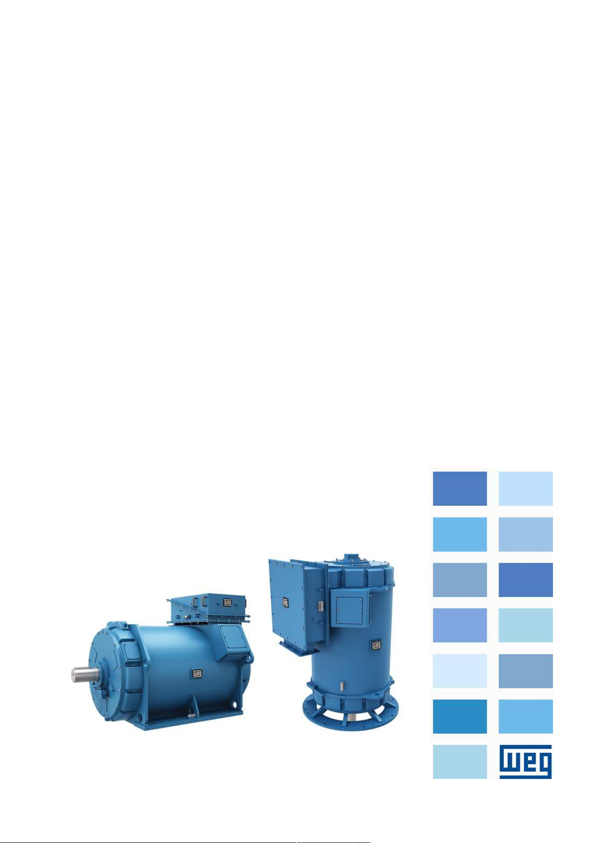
Three phase induction motors
cooled by water jacket
WGM20 line - Squirrel cage rotor
Horizontal and Vertical
Installation, Operation and Maintenance Manual
Page 2

Page 3

Installation, Operation and Maintenance Manual
Document Number: 10005256831
Material number: 14108242
Model: WGM20
Language: English
Revision: 01
March 2018
Page 4

Page 5
www.weg.net
Dear Customer,
Thank you for purchasing a WEG motor. Our products are developed with the highest standards of
quality and efficiency which ensures outstanding performance.
Since electric motors play a major role in the comfort and well-being of mankind, it must be identified
and treated as a driving machine with characteristics that involve specific care, such as proper
storage, installation and maintenance
All efforts have been made to ensure that the information contained in this manual is faithful to the
configurations and applications of the motor.
Therefore, we recommend that you read this manual carefully before proceeding with the installation,
operation or maintenance of the motor in order to ensure safe and reliable operation of your
equipment and facility. If you need any further information, please contact WEG.
Always keep this manual close to the motor, so that it can be consulted whenever necessary.
ATTENTION
1. It is imperative to follow the procedures contained in this manual for the warranty to be valid;
2. The motor installation, operation and maintenance procedures must be performed only by qualified
personnel.
NOTES
1. The total or partial reproduction of information supplied in this manual is authorized, provided that
reference is made to its source. If this manual is lost, an electronic PDF file is available at www.weg.net
or another printed copy may be requested.
WEG EQUIPAMENTOS ELÉTRICOS S.A.
14108242 Installation, operation and maintenance manual – Squirrel cage motor – WGM20 Line l 5
Page 6

Page 7

TABLE OF CONTENTS
www.weg.net
1 INTRODUCTION ............................................................................................... 11
1.1 SAFETY WARNINGS IN THE MANUAL ........................................................................................... 11
2 GENERAL INSTRUCTIONS ............................................................................... 12
2.1 QUALIFIED PERSONNEL ................................................................................................................ 12
2.2 SAFETY INSTRUCTIONS ................................................................................................................ 12
2.3 STANDARDS ................................................................................................................................... 12
2.4 ENVIRONMENTAL CONDITIONS .................................................................................................... 13
2.5 OPERATING CONDITIONS ............................................................................................................. 13
2.6 VOLTAGE AND FREQUENCY ......................................................................................................... 13
3 RECEIVING, HANDLING AND STORAGE ........................................................... 14
3.1 RECEIVING ..................................................................................................................................... 14
3.2 HANDLING ...................................................................................................................................... 14
3.2.1 Horizontal motor handling ................................................................................................................... 14
3.2.2 Vertical motor handling ....................................................................................................................... 15
3.2.3 Vertical motor positioning .................................................................................................................... 15
3.3 STORAGE ....................................................................................................................................... 15
3.3.1 Outdoor storage ................................................................................................................................. 15
3.3.2 Long term storage .............................................................................................................................. 15
3.3.2.1 Storage location .................................................................................................................. 16
3.3.2.1.1 Indoor storage ................................................................................................ 16
3.3.2.1.2 Outdoor storage ............................................................................................. 16
3.3.2.2 Separate parts .................................................................................................................... 16
3.3.3 Preservation during the storage ........................................................................................................... 16
3.3.3.1 Cooling system ................................................................................................................... 16
3.3.3.2 Space heater ....................................................................................................................... 16
3.3.3.3 Insulation resistance ............................................................................................................ 17
3.3.3.4 Exposed machined surfaces ................................................................................................ 17
3.3.3.5 Sealing ................................................................................................................................ 17
3.3.3.6 Bearings .............................................................................................................................. 17
3.3.3.7 Terminal boxes .................................................................................................................... 17
3.3.3.8 Cleanliness and conservation of the motor during storage ................................................... 17
3.3.3.9 Inspections and records during storage ............................................................................... 17
3.3.3.10 Predictive/preventive maintenance....................................................................................... 17
3.3.3.11 Maintenance plan during storage ......................................................................................... 18
3.3.4 Preparation for commissioning ............................................................................................................ 18
3.3.4.1 Cleaning .............................................................................................................................. 18
3.3.4.2 Bearing lubrication ............................................................................................................... 18
3.3.4.3 Insulation resistance verification ........................................................................................... 18
3.3.4.4 Cooling system ................................................................................................................... 18
3.3.4.5 Others ................................................................................................................................. 18
4 INSTALLATION ................................................................................................. 19
4.1 INSTALLATION SITE ....................................................................................................................... 19
4.2 SHAFT LOCK .................................................................................................................................. 19
4.3 ROTATION DIRECTION ................................................................................................................... 19
4.4 INSULATION RESISTANCE ............................................................................................................. 19
4.4.1 Safety Instructions .............................................................................................................................. 19
4.4.2 General considerations ....................................................................................................................... 19
4.4.3 Measurement on the stator windings................................................................................................... 19
4.4.4 Additional Information ......................................................................................................................... 20
4.4.5 Polarization Index ................................................................................................................................ 20
4.4.6 Conversion of the measured values ..................................................................................................... 20
4.4.7 Insulation assessment ......................................................................................................................... 20
4.5 PROTECTIONS ............................................................................................................................... 21
4.5.1 Thermal protections ............................................................................................................................ 21
4.5.2 Temperature limits for the windings ..................................................................................................... 21
4.5.3 Alarm and trip temperatures ................................................................................................................ 21
4.5.4 Installation of temperature sensors ...................................................................................................... 22
4.5.5 Temperature and ohmic resistance of the PT100 thermoresistance ..................................................... 23
4.5.6 Space heater ...................................................................................................................................... 23
4.5.7 Water leak sensor ............................................................................................................................... 23
14108242 Installation, operation and maintenance manual – Squirrel cage motor – WGM20 Line l 7
Page 8

www.weg.net
4.5.8 Water temperature sensor ...................................................................................................................23
4.6 COOLING ....................................................................................................................................... 24
4.6.1 Cooling system ...................................................................................................................................24
4.6.1.1 Cooling system characteristics ........................................................................................... 24
4.6.1.2 Cooling water characteristics .............................................................................................. 24
4.6.1.3 Cooling water temperature ................................................................................................. 24
4.6.1.4 Protective devices .............................................................................................................. 24
4.7 ELECTRICAL ASPECTS ................................................................................................................. 25
4.7.1 Electrical connections .........................................................................................................................25
4.7.1.1 Main electrical connections ................................................................................................. 25
4.7.1.2 Grounding .......................................................................................................................... 25
4.7.2 Connection diagram ............................................................................................................................25
4.7.3 Accessories connection diagram .........................................................................................................25
4.8 MECHANICAL ASPECTS ............................................................................................................... 25
4.8.1 Base ...................................................................................................................................................25
4.8.2 Base loads ..........................................................................................................................................26
4.8.3 Base types ..........................................................................................................................................26
4.8.3.1 Concrete base .................................................................................................................... 26
4.8.3.2 Sliding base ........................................................................................................................ 26
4.8.3.3 Metal base ......................................................................................................................... 26
4.8.3.4 Anchor bolts ....................................................................................................................... 26
4.8.4 Natural frequency of the base ..............................................................................................................26
4.8.5 Leveling ..............................................................................................................................................27
4.8.6 Alignment ............................................................................................................................................27
4.8.7 Doweling .............................................................................................................................................28
4.8.8 Couplings ...........................................................................................................................................28
4.8.8.1 Direct coupling ................................................................................................................... 28
4.8.8.2 Gear coupling ..................................................................................................................... 28
4.8.8.3 Belt drive ............................................................................................................................ 28
5 STARTING ........................................................................................................ 30
5.1 DIRECT ON-LINE STARTING ......................................................................................................... 30
5.2 DIRECT ONLINE STARTING FREQUENCY ..................................................................................... 30
5.3 LOCKED ROTOR CURRENT .......................................................................................................... 30
5.4 STARTING WITH REDUCED CURRENT ......................................................................................... 30
6 COMMISSIONING ............................................................................................. 31
6.1 PRELIMINARY INSPECTION .......................................................................................................... 31
6.2 FIRST STARTING ........................................................................................................................... 31
6.3 OPERATION ................................................................................................................................... 31
6.3.1 General ...............................................................................................................................................31
6.3.2 Temperatures......................................................................................................................................32
6.3.3 Bearings .............................................................................................................................................32
6.3.4 Cooling system ...................................................................................................................................32
6.3.5 Vibration .............................................................................................................................................32
6.3.6 Shutdown ...........................................................................................................................................32
7 MAINTENANCE ................................................................................................. 33
7.1 GENERAL ....................................................................................................................................... 33
7.2 GENERAL CLEANING .................................................................................................................... 33
7.3 WINDING INSPECTIONS ................................................................................................................ 33
7.4 WINDING CLEANING ..................................................................................................................... 33
7.4.1 Inspections .........................................................................................................................................33
7.4.2 Reimpregnation ...................................................................................................................................34
7.4.3 Insulation Resistance ...........................................................................................................................34
7.5 COOLING SYSTEM MAINTENANCE .............................................................................................. 34
7.5.1 Cleaning..............................................................................................................................................34
7.5.1.1 Motor end shield disassembly ............................................................................................. 34
7.5.1.2 Cooling heads disassembly ................................................................................................ 35
7.5.1.3 Inspection and cleaning of water channels .......................................................................... 35
7.5.1.4 End shields and cooling heads assembly ............................................................................ 35
7.6 VIBRATION ..................................................................................................................................... 35
7.7 MOTOR OUT OF OPERATION ....................................................................................................... 35
7.8 SHAFT GROUNDING DEVICE ........................................................................................................ 35
7.9 ENCODER MAINTENANCE ............................................................................................................ 36
8 l Installation, operation and maintenance manual – Squirrel cage motor – WGM20 Line 14108242
Page 9

www.weg.net
7.10 BEARING MAINTENANCE .............................................................................................................. 36
7.10.1 Bearing data ....................................................................................................................................... 36
7.10.2 Instructions for lubrication ................................................................................................................... 36
7.10.3 Procedures for bearing lubrication ....................................................................................................... 36
7.10.4 Type and amount of grease ................................................................................................................ 37
7.10.5 Alternative greases .............................................................................................................................. 37
7.10.6 Procedure for changing the grease ..................................................................................................... 37
7.10.7 Low temperature greases ................................................................................................................... 38
7.10.8 Grease compatibility ........................................................................................................................... 38
7.10.9 Bearing disassembly ........................................................................................................................... 38
7.10.9.1 DE horizontal bearing disassembly ...................................................................................... 39
7.10.9.2 NDE horizontal bearing disassembly .................................................................................... 39
7.10.9.3 DE vertical bearing disassembly .......................................................................................... 40
7.10.9.4 NDE vertical bearing disassembly ........................................................................................ 40
7.10.9.5 Bearing assembly ................................................................................................................ 41
7.10.9.6 Bearing insulation ................................................................................................................ 41
7.10.10Rolling bearing replacement ................................................................................................................ 41
7.10.11Bearing protection .............................................................................................................................. 41
7.10.11.1 Protection settings .............................................................................................................. 41
7.11 ACCESSORIES MAINTENANCE ....................................................................................................... 42
8 MOTOR DISASSEMBLY AND ASSEMBLY .......................................................... 43
8.1 HORIZONTAL MOTORS.................................................................................................................. 43
8.1.1 Disassembly ....................................................................................................................................... 43
8.1.2 Assembly ............................................................................................................................................ 43
8.2 VERTICAL MOTORS ....................................................................................................................... 44
8.2.1 Disassembly ....................................................................................................................................... 44
8.2.2 Assembly ............................................................................................................................................ 44
8.3 AIR-GAP MEASUREMENT .............................................................................................................. 45
8.4 TIGHTENING TORQUE ................................................................................................................... 45
8.5 SPARE PARTS ................................................................................................................................ 45
8.5.1 Necessary spare parts ........................................................................................................................ 45
8.5.2 Optional spare parts ........................................................................................................................... 45
9 MAINTENANCE PLAN ....................................................................................... 46
10 ABNORMALITIES, CAUSES AND SOLUTIONS ................................................... 47
11 ENVIRONMENTAL INFORMATION ..................................................................... 48
11.1 PACKAGE ....................................................................................................................................... 48
11.2 PRODUCT ....................................................................................................................................... 48
11.3 HAZARDOUS WASTE ..................................................................................................................... 48
12 DECLARATION OF CONFORMITY ..................................................................... 49
13 SERVICE NETWORK ........................................................................................ 50
14 WARRANTY TERM ........................................................................................... 50
14108242 Installation, operation and maintenance manual – Squirrel cage motor – WGM20 Line l 9
Page 10

Page 11
www.weg.net
1 INTRODUCTION
This manual contains information regarding low and high-voltage, three-phase induction motors.
Motors with special features can be supplied with specific documents (drawings, connection diagram, characteristic curves
etc.). Those documents, together with this manual, must be thoroughly evaluated before proceeding with the installation,
operation or maintenance of the motor.
In order to use a frequency inverter, it is mandatory to follow the instructions contained in the specific technical
documentation of the motor and in the manual of the frequency inverter.
If any additional explanation about motors with major special features is necessary, consult WEG. All procedures and
standards contained in this manual must be observed in order to ensure proper operation of the motor and the safety of the
personnel involved in its operation. Following these procedures is also important to ensure the validity of the motor warranty.
Thus, we recommend the careful reading of this manual before the installation and operation of the motor. If any further
information is still necessary, consult WEG.
1.1 SAFETY WARNINGS IN THE MANUAL
In this manual, the following safety warnings are used:
DANGER
Failure to observe the procedures recommend in this warning may result in death, serious injuries and
extensive equipment damage.
ATTENTION
Failure to observe the procedures recommend in this warning may result in equipment damage.
NOTE
This provides important information for correct understanding and proper operation of the product.
14108242 Installation, operation and maintenance manual – Squirrel cage motor – WGM20 Line l 11
Page 12
www.weg.net
Thus, the operation with open terminal
ATTENTION
ATTENTION
IEC60034
-1
MG1
-
IEC60072
IEC60034
-2
Levels of
IEC60034
-6
IEC60034
-7
IEC60034
-9
Mechanical
IEC60034
-
14
Mechanical
2 GENERAL INSTRUCTIONS
All the personnel involved with the assembly, operation or maintenance of electrical installations must be permanently
informed and updated on the standards and safety instructions that guide the job and are advised to strictly comply with
them. Before beginning any job, the person in charge must make sure that all points have been duly observed and warn the
respective personnel about the danger inherent to the task to be performed.
Improper application, inadequate handled or maintenance of the generator, may cause serious injuries and/or material
damages.
Therefore, it is highly recommended that these services be always performed by qualified personnel.
2.1 QUALIFIED PERSONNEL
The term qualified personnel means those who, because
of their training, experience, education level, and
knowledge of the applicable standards, specifications,
accident prevention, safety standards and operating
conditions, have been authorized by the persons in charge
to execute the necessary tasks, and who are able to
recognize and avoid any possible danger.
Such qualified personnel must also know and be able to
provide first aid procedures if necessary.
The entire start-up, maintenance and repair tasks must
only be performed by qualified personnel.
2.2 SAFETY INSTRUCTIONS
DANGER
During normal operation of this equipment, a
hazard associated with energized or rotating
components with high voltage or elevated
temperatures exists.
boxes, unprotected couplings, improper
handling, or failure to comply with the
operating standards, may cause severe
personal injuries and material damages.
When devices and equipment are used
outside the industrial environment, the user
must ensure the safety of the equipment by
adopting proper protection and safety
measures during installation (for example,
keep people away, avoid contact of children,
etc.).
Those responsible for the safety of the installation must
ensure that:
Only qualified personnel install and operate the
equipment;
They have this manual and all other documents
supplied with the motor at hand, as well as that they
perform the tasks in strict compliance with the service
instructions, relevant standards and specific product
documentation;
Failure to comply with installation and safety
standards may void the product warranty.
Firefighting equipment and first aid notices
must be available in visible and easily
accessible locations at the work site.
You should also note:
All the technical data regarding the allowed applications
(operating conditions, connections and installation
environment), included in the catalog, in the purchase
order documents, in the operating instructions, in
manuals and all other documentation;
The specific regulations and conditions for the local
installation;
The use of suitable tools and equipment for handling
and transportation;
That the protective devices of the individual
components are removed shortly before installation.
Individual parts must be stored in vibration-free
environments, avoiding falls and ensuring their protection
against aggressive agents and/or that they do not
jeopardize people.
2.3 STANDARDS
The motors are specified, designed, manufactured and
tested according to the standards described in Table 2.1.
The applicable standards are specified in the commercial
contract, which may indicate other national or international
standards, depending on the application or installation
location.
Specification
Dimensions
Terminal marking
Tolerances
Table 2.1: Applicable standards
Tests
protection
Cooling
Mounting
Noise
Vibration
Balancing ISO1940 MG1-7
IEC / NBR NEMA
NBR 17094
NBR 15623
NBR 5383
IEC60034-5
NBR IEC 60034-5
NBR IEC 60034-6
NBR IEC 60034-7
NBR IEC 60034-9
NBR IEC 60034-14
IEC60034-8 / NBR 15367 MG1-2
ISO286 / NBR6158 MG1-4
1,10,20
MG1-4,11
MG1-12
MG1-5
MG1-6
MG1-4
MG1-9
MG1-7
12 l Installation, operation and maintenance manual – Squirrel cage motor – WGM20 Line 14108242
Page 13
2.4 ENVIRONMENTAL CONDITIONS
ATTENTION
°C, antifreeze
The motor was designed according to the specific
environmental conditions (temperature and altitude) of
your application, and are described on the nameplate and
in the datasheet of the motor.
For the use of water-cooled motors in
ambient temperatures below +5
additives must be added to the water.
2.5 OPERATING CONDITIONS
In order for the product warranty to be valid, the motor
must be operated according to nominal data indicated on
its nameplate, observing all applicable standards and
information contained in this manual.
www.weg.net
2.6 VOLTAGE AND FREQUENCY
It is very important to ensure a proper power supply for
the motor. The conductors and the entire protection
system must ensure the quality of the power supply at the
motor terminals within the limits, in accordance with the
IEC60034-1 standard:
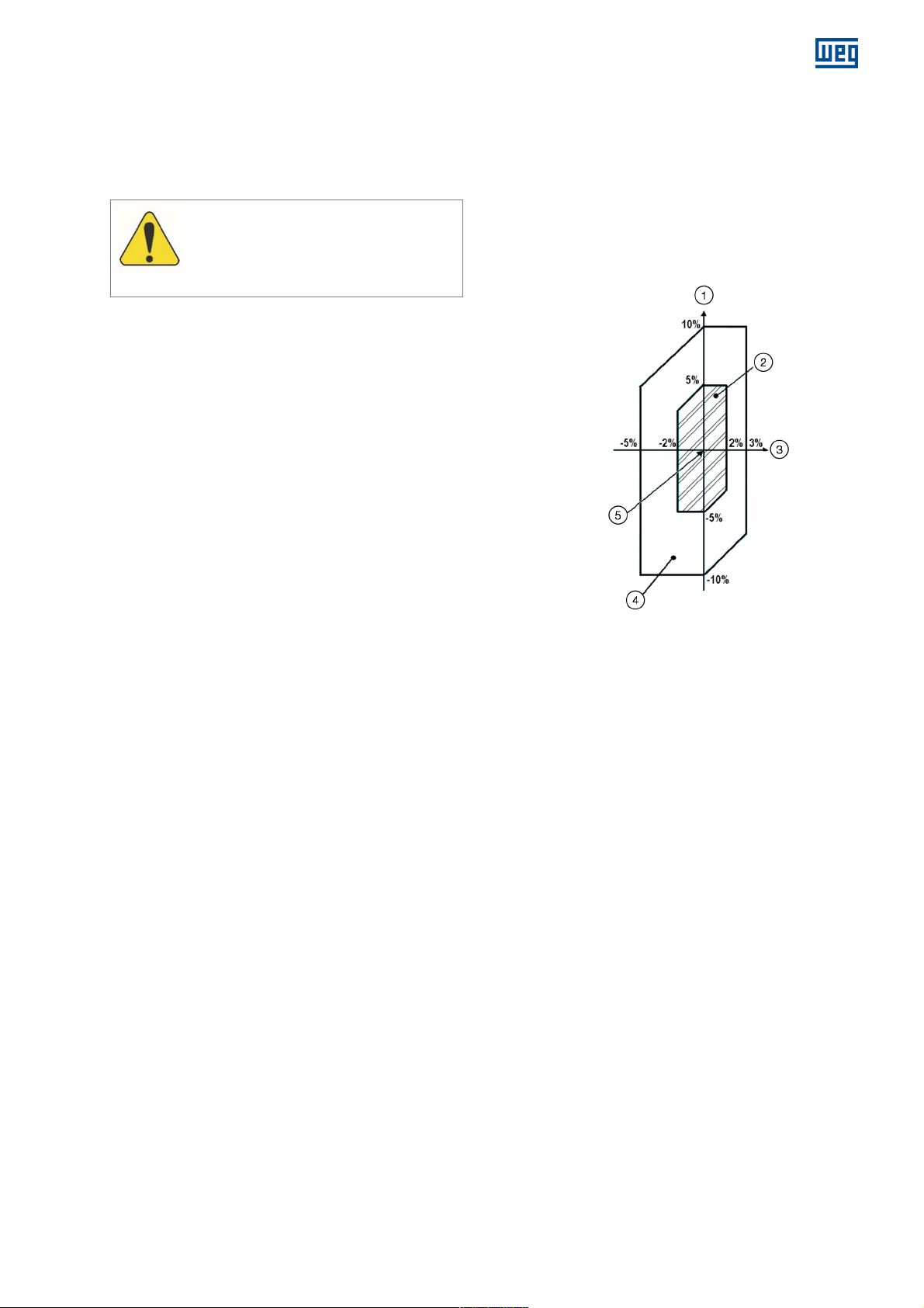
Voltage: may vary within a range of ±10% of the rated
value;
Frequency: may vary within a range of -5% to +3% of
the rated value.
Figure 2.1: Voltage and frequency variation limits
Figure 2.1 legend:
1. Voltage
2. Zone A
3. Frequency
4. Zone B (outside zone A)
5. Voltage with rated characteristics
The motor must be able to perform its main function
continuously in Zone A, but it may not fully meet its
performance characteristics at rated voltage and
frequency (refer to the point with rated characteristics in
Figure 2.1), when it may present some deviations. The
temperature rises may be above those at rated voltage
and frequency.
The motor must be able to perform its main function in
Zone B, but regarding the performance characteristics at
rated voltage and frequency, it may present deviations
greater than those of Zone A. The temperature rises may
be higher than those observed at rated voltage and
frequency, and they will most likely be higher than those in
Zone A.
Prolonged operation in the periphery of Zone B is not
recommended.
14108242 Installation, operation and maintenance manual – Squirrel cage motor – WGM20 Line l 13
Page 14
www.weg.net
ATTENTION
Any damage must be photographed,
documented and reported immediately to the
ATTENTION
ATTENTION
or transport the motor, the
must be able
lifting
LIFTING LUGS
3 RECEIVING, HANDLING AND STORAGE
3.1 RECEIVING
All motors were tested and are in perfect operating
conditions. The machined surfaces are protected against
corrosion. The package must be inspected upon receipt
for occasional damages during transportation.
carrier, the insurer and WEG. The noncommunication of this damage will void the
warranty.
Parts supplied in additional packages must be
checked upon receipt.
When lifting the package (or container), the proper
hoisting points, the weight indicated on the package or
on the nameplate and the operating capacity and
conditions of the hoisting equipment must be observed;
Motors packed in wooden crates must always be lifted
by their own lifting lugs or by a proper forklift; they must
never be lifted by the package;
The package can never be overturned. Place it on the
floor carefully (without impact) in order to avoid damage
to the bearing;
Do not remove the grease for protection against
corrosion from the shaft end, or the closing plugs
present in the terminal box holes. These protections
must remain in place until the moment of the final
assembly.
A complete visual inspection of the motor must be
arried out after removing the package;
c
The shaft locking system must be removed just before
the installation and stored to be used in future
transportation of the motor.
3.2 HANDLING
In order to move
shaft must be locked with the locking
device supplied with the motor.
Lifting equipment and devices
to withstand the motor weight.
Failure to comply with these
recommendations may cause damage to the
equipment, personal injuries or both.
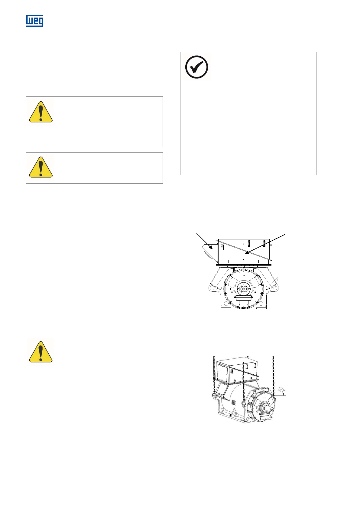
3.2.1 Horizontal motor handling
Horizontal motors must be handled as shown in Figure
3.2.
In order to lift the motor, use only the lifting lugs provided
for that purpose.
CABLES GUIDE TERMINAL BOX
Remove the cable guide and lift the motor, as shown in
Figure 3.2.
NOTES
Observe the indicated weight. Do not lift
the motor causing jolts or put it down
abruptly on the floor, because this may
cause damage to the bearings;
In order to lift the motor, use only the
lugs provided for that purpose. If
necessary, use a crossbeam to protect
parts of the motor.
The lifting lugs on the heat exchanger, end
shields, bearings, radiator, terminal box,
etc. are designed to handle these
components only separately;
Never use the shaft to lift the motor;
The frame lifting lugs are intended to lift
nly the motor. Never use them to lift the
o
motor-driven machine set.
Figure 3.1: Horizontal motor handling
14 l Installation, operation and maintenance manual – Squirrel cage motor – WGM20 Line 14108242
Figure 3.2: Motor handling
Page 15
ATTENTION
recommendations may cause damage to the
ATTENTION
Any damage to the paint
ATTENTION
To assure that the motor warranty be valid, it
3.2.2 Vertical motor handling
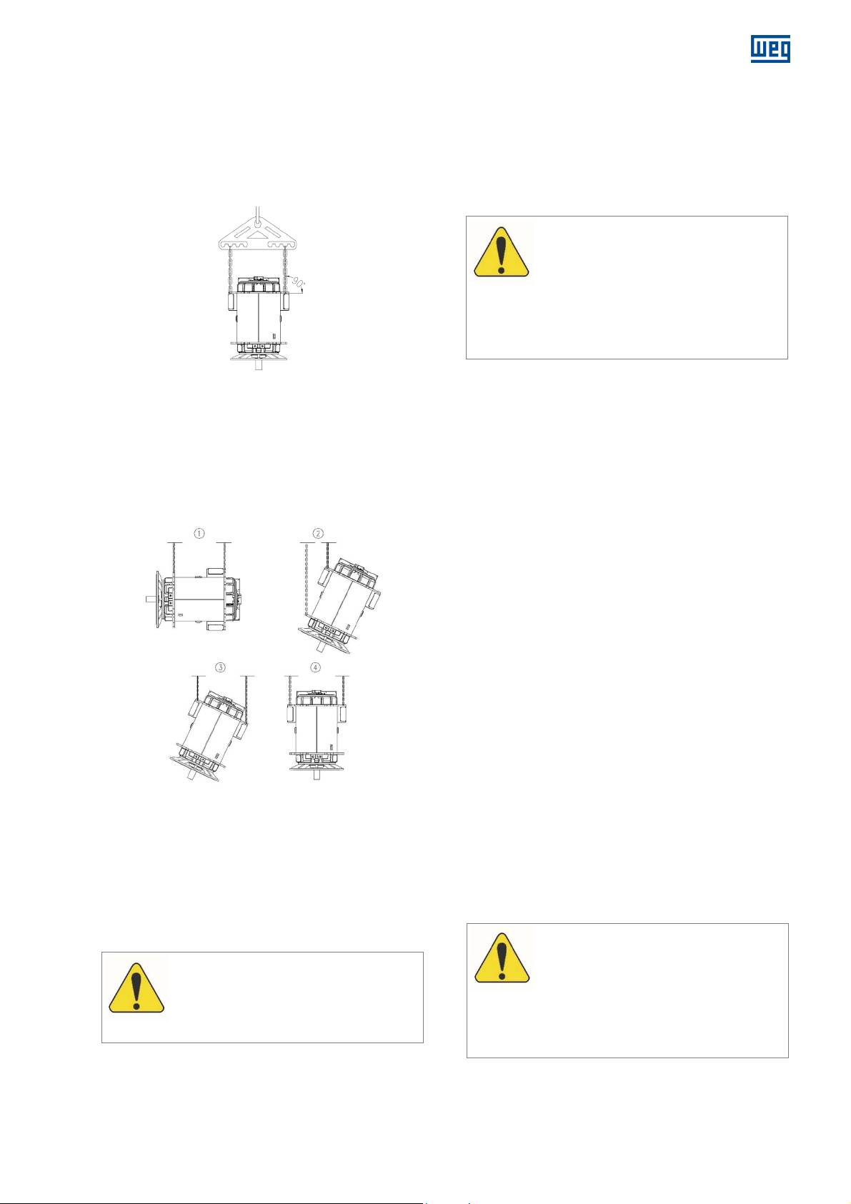
Vertical motors must be handled as shown in Figure 3.3;
Always use the upper lifting lugs of the motor for handling
it in the vertical position, making sure the chains and
cables are also in the vertical position, avoiding too much
stress on the lifting lugs.
www.weg.net
3.3 STORAGE
If the Motor is not installed immediately after reception, it
must remain inside the package and stored in a location
protected against moisture, vapors, sudden changes in
temperature, rodents and insects.
The motor must be stored in vibration-free locations in
order to avoid bearing damage.
Figure 3.3: Vertical motor handling
3.2.3 Vertical motor positioning
Vertical motors are supplied with lifting lugs at the drive
end DE and non-drive end NDE.
Some motors are transported in the horizontal position
and need to be moved to the original position. The
following procedure shows how to move motors from the
horizontal position to the vertical position and vice versa.
Figure 3.4: Vertical motor positioning
1. Lift the motor with the side lifting lugs using two hoists;
2. Lower the motor drive end (DE) and lift the non-drive
end (NDE) at the same time until balance is reached;
3. Loosen the DE cables and turn the motor 180º in
order to enable the connection of these cables to the
other lifting lugs of the NDE;
4. Connect the loose cables to the NDE lifting lugs and
lift them until the motor reaches the vertical position.
Space heaters must remain powered during
storage in order to avoid moisture
condensation inside the motor.
protection of the machined parts must be
repaired.
or corrosion
3.3.1 Outdoor storage
The motor must be stored in a dry location, free of
flooding and vibrations.
Repair any damages on the package before storing the
motor, which is needed to ensure proper storage
conditions.
Place the motor on platforms or foundations that ensure
protection against humidity from the ground and prevent it
from sinking into the soil. Free air circulation underneath
the motor must be assured.
The cover used to protect the motor against the bad
weather must not be in contact with its surfaces. In order
to ensure free air circulation between the motor and such
covers, place wooden blocks as spacers.
3.3.2 Long term storage
When the motor is stored for a long period of time (two
months or more) before start-up, it is exposed to
external agents, such as temperature variations,
moisture, aggressive agents, etc.
The empty spaces inside the motor – such as rolling
bearings, terminal boxes, and windings – are exposed to
humidity, which can cause condensation, and,
depending on the degree of air contamination,
aggressive substances may also penetrate these empty
spaces.
Consequently, after long periods of storage, the winding
insulation resistance may drop below the acceptable
values, internal components, such as rolling bearings,
may oxidize, and the lubricant power of the lubricant
agent in the bearings may be adversely affected.
All of these influences increase the risk of damages
before starting the motor.
Failure to comply with these
equipment, personal injuries or both.
14108242 Installation, operation and maintenance manual – Squirrel cage motor – WGM20 Line l 15
is necessary to make sure that all preventive
measures described in this manual, such as
constructive aspects, maintenance,
packaging, storage, and periodical
inspections, are followed and recorded.
Page 16
www.weg.net
ATTENTION
ATTENTION
The instructions for long term storage are valid for motors
that remain stored for long periods (two months or more)
before start-up or motors already installed that are in a
prolonged stoppage, considering the same period.
3.3.2.1 Storage location
In order to ensure the best storage conditions for the
motor during long periods, the chosen location must
strictly meet the criteria described in sections 3.3.2.1.1
and 3.3.2.1.2.
3.3.2.1.1 Indoor storage
In order to ensure better storage conditions for the motor,
the storage site must comply strictly with the criteria
described below:
The storage site must be closed, covered, dry, free
air contaminants (moisture, vapor, dust, particles and
aggressive fumes) and free of flooding;
The site should be protected against sudden
temperature variations, humidity, rodents and insects;
Vibration-free location, to avoid damaging to the motor
bearings;
The floor must be of leveled concrete with resistant
structure to support the motor weight;
Must have system to fire detection and extinguishing;
Be provided with electricity for supplying the space
heaters with power failure detection system;
Exclusive site to store electrical machines (do not mix
with other equipment and/or products that could
prejudice the correct motor storage);
Site with facilities of cargo handling services, suitable to
allow the motor handling and removal;
There must be no gas present, such as chlorine, sulfur
dioxide or acids;
The site must have ventilation system with air filter;
Ambient temperature between 5°C and 50°C, and
should not present sudden temperature variation;
Relative air humidity <50%;
Must have prevention against dirt and dust depositio
The motor should be stored on a suitable metal base
that prevents the absorption of moisture from the floor.
If any of these requirements is not met in the storage site,
WEG suggests that additional protections be added to the
motor package during the storage period, as follows:
A closed wooden crate or the like with an electrical
installation that allows the energization of the space
heaters;
If there is a risk of infestation and fungus formation, the
package must be protected in the storage place by
spraying it or painting it with appropriate chemicals;
The package preparation must be prepared carefully by
an experienced person.
of
n;
3.3.2.1.2 Outdoor storage
moisture and other odd materials, using resistant
canvas or plastic.
The package must be placed on platforms or
f
oundations that ensure protection against dirt and
moisture and prevent it from sinking into the soil;
After the package is covered, a shelter must be erected
to protect it against direct rain, snow and excessive sun
heat.
In case the motor remains stored for long
periods (two months or more), it is
recommended to inspect it regularly as
specified in the section 3.3.3.11 of this
manual.
3.3.2.2 Separate parts
If parts are supplied separately (terminal boxes, heat
exchanger, end shields, etc.), these parts must be
mounted on motor to store it;
Spare parts must be stored in an adequate place, as
specified in sections 3.3.2.1.1 and 3.3.2.1.2 of this
manual.
The relative humidity inside the package must not
exceed 50%.
Rolling bearings must not be subject to shocks, falls or
storage with vibration or humidity, which can cause
marks on the internal tracks or on the balls, reducing
their useful life.
3.3.3 Preservation during the storage
3.3.3.1 Cooling system
After the motor operation, to preserve the cooling system
during long term storage, the following criteria must be
strictly observed:
Blow hot air in one of the holes for 15 to 20 minutes
eliminate the moisture from inside the frame inner
channels;
After drying, the water inlet and outlet should be closed.
, to
3.3.3.2 Space heater
Space heaters must remain powered during storage to
avoid moisture condensation inside the motor and ensure
that the winding insulation resistance remains within
acceptable levels.
The space heaters drive circuit must be unique and the
voltage and current of this circuit must be measured and
recorded monthly.
It is recommended that a signal be installed near the
motor to indicate that the space heaters are energized.
In case outdoor storage is unavoidable, the motor must be
packed in specific packaging for such conditions, as
follows:
For outdoor storage (exposed to the weather), besides
16 l Installation, operation and maintenance manual – Squirrel cage motor – WGM20 Line 14108242
Outdoor storage of the motor is not
recommended.
the packaging recommended for indoor storage, the
package must be covered with protection against dust,
Page 17
3.3.3.3 Insulation resistance
ATTENTION
complete turns
ATTENTION
During the storage period, the insulation resistance of the
motor windings must be measured and recorded every
two months, and before the motor installation or eventually
if there is any change in the preservation process (E.g.
prolonged lack of power).
The measurement procedures and the criteria for
acceptance of the results shall be according to IEEE-43
Standard.
Any insulation resistance reduction must be investigated.
3.3.3.4 Exposed machined surfaces
All exposed machined surfaces (e.g., shaft end and
flanges) are protected at the factory with a temporary
protective agent (rust inhibitor).
This protection coating must be reapplied at least every
six months or when removed and/or damaged.
rotective agent Anticorit BW
Recommended Product:
Supplier
: Fuchs
P
3.3.3.5 Sealing
The rubber seals, gaskets, plugs and cable glands of the
motor shall be inspected annually and replaced, if
necessary.
3.3.3.6 Bearings
The rolling bearings are lubricated at the factory for
motor testing.
In order to keep the bearings in good
condition during the storage period,
the
shaft locking device must be removed
every two months, and the motor rotor
must be rotated at least 10
at 30 rpm
preserve the internal parts of the bearings.
to circulate the grease and
Before putting the motor into operation, the rolling
bearings must be lubricated;
If the motor remains stored for a period exceeding two
years, the rolling bearings must be disassembled,
washed, inspected and relubricated.
3.3.3.7 Terminal boxes
When the insulation resistance of the motor windings is
measured, the main terminal box and the other terminal
boxes must also be inspected, observing the following
aspects:
The inside must be dry, clean and free of any dust
accumulation;
The contact elements cannot present corrosion;
The seals must be in proper condition;
The cable inlets must be correctly sealed.
www.weg.net
If any of these items are not accordingly,
clean or replace the damaged parts.
3.3.3.8 Cleanliness and conservation of the motor during storage
The motor should be free of oil, water, dust and dirt.
The motor outside must be cleaned with compressed
air at reduced pressure;
Remove the removable rust signs with a clean cloth
soaked in petroleum solvent.
Check if the bearings and lubrication nipples are free of
dust and dirt and if the bearing plugs are properly
tightened.
Risks, marks or rust on the shaft-end should be
emoved carefully.
r
3.3.3.9 Inspections and records during storage
The stored motor must be inspected periodically and
inspection records must be filed.
The following items must be inspected:
1. Check the motor for physical damages and repair it, if
necessary;
2. Inspection of the cleanliness conditions;
3. Check for signs of water condensation inside the
motor;
4. Check of the protective coating conditions of the
exposed machined parts;
5. Check the paint conditions, and repair if necessary;
6. Check for aggressive agents signs;
7. Check the operation of the space heaters.
8. Measure and record the temperature, insulation
resistance and polarization index of the stator winding;
9. Make sure that the storage location complies with the
criteria described in section 3.3.2.1.
3.3.3.10 Predictive/preventive maintenance
WEG recommends that, every 3 years of storage, the
stored motor be sent to a WEG Authorized Repair Shop or
to WEG own factory, in order to perform a complete
predictive maintenance.
The complete predictive maintenance procedure
comprises disassembling the complete motor for
inspection and, after assembly, performing a routine test in
the laboratory.
14108242 Installation, operation and maintenance manual – Squirrel cage motor – WGM20 Line l 17
Page 18
www.weg.net
Inspect the humidity and temperature
Check the function of the signal system (if
Check
the rust inhibitor
on the exposed
Drain the water condensed inside the motor
If the storage period exceeds 2
3.3.3.11 Maintenance plan during storage
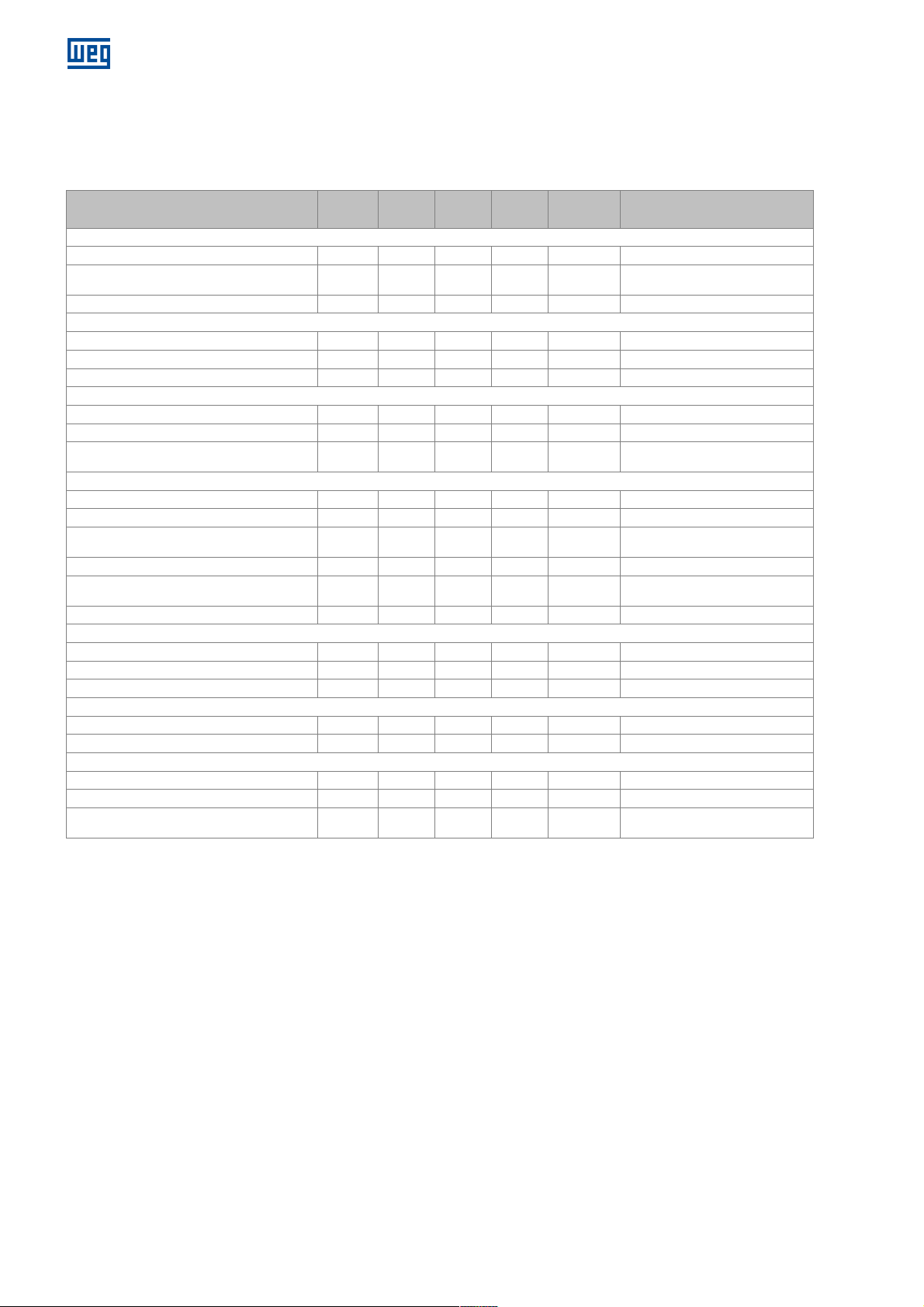
During the storage period, the motor maintenance must be performed and recorded according to the plan described in
Table 3.1.
Monthly
Inspect the cleanliness conditions
conditions
Inspect for insect infestation signs
Inspect for damages
Check the internal relative humidity
Replace the desiccant in the package (if any)
Check the operating conditions
Measure the circuit voltage and frequency
any)
Perform external cleaning
Check the painting conditions
machined parts
Reapply the rust inhibitor
(if any)
Complete predictive maintenance
Measure the winding temperature
Measure the insulation resistance
Measure the polarization index
TERMINAL BOX AND GROUNDING TERMINALS
Clean the interior of the terminal boxes
Inspect the seals and gaskets
Rotate the shaft
Relubricate the bearing
Disassemble and clean the bearing
3.3.4 Preparation for commissioning
3.3.4.1 Cleaning
The internal and external parts of the motor must be
free of oil, water, dust and dirt.
Remove the rust inhibitor from the exposed surfaces
with a cloth damped in a petroleum-based solvent;
Make sure that the bearings and cavities used for
lubrication are free of dirt and that the cavity plugs are
correctly sealed and tightened. Oxidation and marks on
the bearing seats and on the shaft must be carefully
removed.
3.3.4.2 Bearing lubrication
Use the lubricant specified for bearing lubrication.
Information on the bearings and lubricants are indicated
on the bearing nameplates, and the lubrication must be
done as described in section 7.10 of this manual, always
considering the type of bearing.
18 l Installation, operation and maintenance manual – Squirrel cage motor – WGM20 Line 14108242
Table 3.1: Storage plan
2
months
STORAGE LOCATION
X
X
X
X
X
X
X
X
X
X
X
X
X
PACKAGE
SPACE HEATER
X
WHOLE MOTOR
WINDINGS
X
X
X
BEARINGS
X
6
months
2 years
Whenever necessary.
X
X
Before
start-up
X
X
According to item 3.3.3.10
X
X
X
X
X
X
years.
3.3.4.3 Insulation resistance verification
Before putting the motor into operation, the insulation
resistance must be measured according to section 4.4.3
of this manual.
3.3.4.4 Cooling system
If the motor remains out of operation for a long term (two
months or more), it must be ensured that water circulates
freely through the motor cooling system, before putting
the motor in operation.
3.3.4.5 Others
Follow the other procedures described in section 6 of this
manual before putting the motor into operation.
Notes
Page 19
4 INSTALLATION
ATTENTION
The
whenever the motor is removed from its base
The shaft end is protected at the factory with
In order to measure the insulation resistance,
The
winding being tested must be connected
Failure to comply with these procedures may
4.1 INSTALLATION SITE
Electric motors must be installed in easily accessible
places, allowing periodic inspections, on-site maintenance
and, if necessary, removal for external services.
The following environmental conditions must be ensured:
Clean and well-ventilated location;
The installation of other equipment or walls must not
block or hinder the motor ventilation;
The area around and above the motor must be
sufficient for maintenance or handling;
The environment must be in accordance with the motor
protection degree.
4.2 SHAFT LOCK
The motor leaves the factory with a lock on the shaft to
prevent damages to the bearings during transportation.
This lock must be removed prior to motor installation.
shaft-locking device must be installed
(uncoupled) in order to prevent damages to
the bearings during transportation.
a temporary protective agent (rust inhibitor).
During the motor installation, it is necessary
to remove this product from the grounding
brush (if any) contact track on the shaft.
4.3 ROTATION DIRECTION
The motor rotation direction is indicated by a plate affixed
to the frame on the drive end and in the motor specific
documentation.
4.4 INSULATION RESISTANCE
4.4.1 Safety Instructions
www.weg.net
to establish fixed rules for the actual value of winding
insulation resistance, as it varies according to the
environmental conditions (temperature, humidity), machine
cleanliness conditions (dust, oil, grease, dirt) and quality
and condition of the insulating material used.
The evaluation of the periodical follow-up records is useful
to conclude whether the motor is able to operate.
4.4.3 Measurement on the stator windings
The insulation resistance must be measured with a
megohmmeter. The testing voltage for the motor
windings must be in accordance with Table 4.1: Voltage for
the winding Insulation resistance test
and IEEE43 standard.
Table 4.1: Voltage for the winding Insulation resistance test
Winding rated
voltage (V)
< 1000 500
1000 - 2500 500 - 1000
2501 - 5000 1000 - 2500
5001 - 12000 2500 - 5000
> 12000 5000 - 10000
Before measuring the stator winding insulation resistance:
Disconnect all connections to the stator terminals;
Disconnect and insulate all CTs and PTs (if any);
Ground the motor frame;
Measure the winding temperature;
Ground all temperature sensors;
Check the humidity.
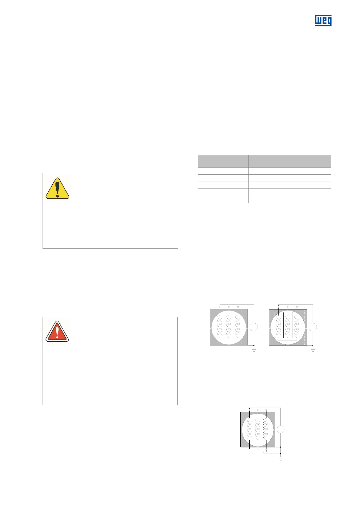
The insulation resistance measurement of the stator
windings must be done in the main terminal box.
The megohmmeter must be connected between the
motor frame and the winding.
The frame must be grounded and the three phases of the
stator winding must remain connected to the neutral point,
according to Figure 4.1.
Insulation resistance test -
continuous voltage (V)
DANGER
MΩ MΩ
the motor must be turned off and stopped.
to the frame and grounded until all residual
electrostatic charges are removed.
Capacitors (if any) must also be grounded
before disconnecting and separating the
terminals to measure the insulation
resistance.
result in personal injury.
Figure 4.1: Megohmmeter connection
Whenever possible, each phase must be isolated and
tested separately. The separate test allows the
comparison between the phases. When a phase is tested,
the other two phases must be grounded to the same
ground of the frame, according to Figure 4.2.
4.4.2 General considerations
When the motor is not immediately put into operation, it
must be protected against moisture, high temperatures,
and dirt, thus avoiding impacts on the insulation
resistance.
The winding insulation resistance must be measured
before putting the motor into operation.
If the environment is too humid, the insulation resistance
must be measured periodically during storage. It is difficult
14108242 Installation, operation and maintenance manual – Squirrel cage motor – WGM20 Line l 19
Figure 4.2: Connection of the megohmmeter to separate phases
MΩ
Page 20
www.weg.net
ATTENTION
obtained in previous tests on the same motor
ATTENTION
After measuring the insulation resistance,
The testing voltage to measure the insulation
Vdc and for the other accessories, 100 Vdc.
In order to avoid accidents, the winding must
be grounded immediately after measuring the
Polarization
Index
Insulation assessment
1 or lower
Unacceptable
< 1.5 Dangerous
1.5 to 2.0
Fair
2.0 to 3.0
Good
3.0 to 4.0
Very Good
> 4.0 Excellent
Winding t
emperatur
e ºC
If the total winding measurement presents a value below
the recommended, the neutral connections must be
opened and the insulation resistance of each phase must
be measured separately.
Much higher values may be frequently
obtained from motors in operation for long
periods of time. Comparison with values
- under similar load, temperature and
humidity conditions – may be an excellent
parameter to evaluate the winding insulation
conditions, instead of using the value
obtained in a single test as the basis.
Significant or sudden reductions are
considered suspicious.
4.4.4 Additional Information
ground the tested winding in order to
discharge it.
resistance of the space heater must be 500
It is not recommended to measure the
insulation resistance of thermal protectors.
4.4.5 Polarization Index
The polarization index is defined by the ratio between the
insulation resistance measured in 10 minutes and the
insulation resistance measured in 1 minute. This
measurement procedure is always carried out at relatively
constant temperatures.
The polarization index allows the assessment of the motor
insulation conditions.
DANGER
insulation resistance.
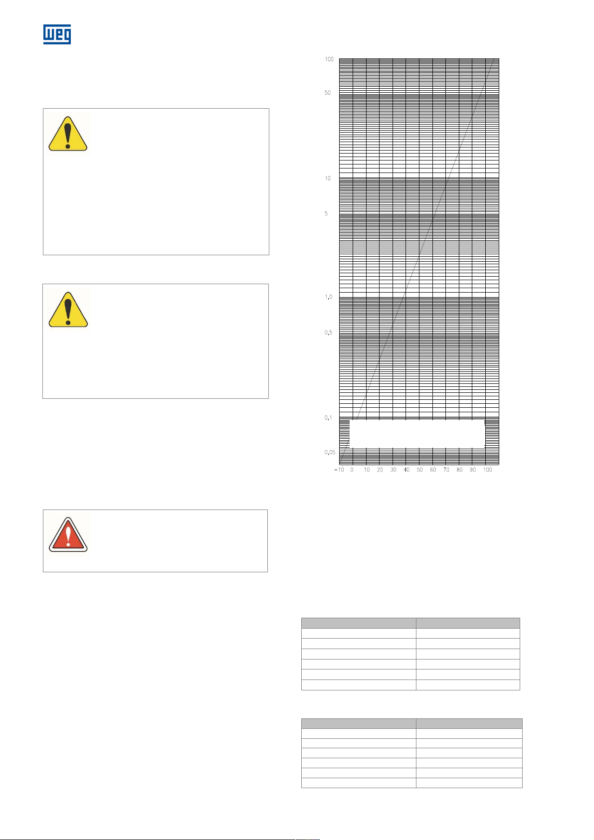
4.4.6 Conversion of the measured values
The insulation resistance must be referred to 40°C. If the
measurement is performed at a different temperature, it is
necessary to correct the reading to 40°C by using a curve
of the insulation resistance variation as a function of the
temperature, obtained at the motor itself. If this curve is
not available, the approximate correction provided by the
curve in Figure 4.3, according to NBR 5383 / IEEE43
standard, may be used.
40ºC
Coefficient of insulation resistance variation Kt
To convert the insulation resistance
measured (Rt) for 40 ºC, multiply by the
temperature coefficient (Kt)
R
= Rt x Kt
40ºC
Figure 4.3: Insulation resistance variation coefficient according to
the temperature
40ºC
4.4.7 Insulation assessment
Table 4.2 and Table 4.3 present guiding limits of insulation
resistance and polarization index for the assessment of
the motor insulation conditions.
Table 4.2: Insulation resistance guiding limits on electrical
Insulation resistance value Insulation assessment
2 MΩ or lower
< 50 MΩ
50...100 MΩ Fair
100...500 MΩ Good
500...1000 MΩ
Table 4.3: Polarization index (ratio between 10 minutes and 1
> 1000 MΩ
machines
Unacceptable
Dangerous
Very Good
Excellent
minute)
20 l Installation, operation and maintenance manual – Squirrel cage motor – WGM20 Line 14108242
Page 21
ATTENTION
B
Ambient temperature
°C 40 40 40
T =
temperature rise (temperature
Difference between the hottest spot and
Total: temperature of the hottest point
°C
130 155 180
ATTENTION
and
Maximum temperature
Alarm
Trip
Winding class F
Winding class F
Bearings
-
110 120
ATTENTION
The alarm and trip
values may be determined
ATTENTION
The motor protection devices are listed
in the
If the measured insulation resistance,
referred to 40 ºC, is below 100 MΩ or the
polarization index is below 2, than before
putting the motor into operation, consult
WEG.
4.5 PROTECTIONS
Motors used in continuous duty must be protected
against overloads by means of a motor integral device, or
an independent protection device, which is generally a
thermal relay with rated or adjustable current equal to or
below the value obtained by multiplying the full load motor
supply current by:
1.25 for motors with service factor equal to or above
1.15;
1.15 for motors with service factor equal to 1.0.
Motors also have protection devices against overheating
(in cases of overloads, locked rotor, low voltage, lack of
motor ventilation).
4.5.1 Thermal protections
The over-temperature protections devices are installed on
the main stator, bearings and other parts that require
temperature monitoring and thermal protection.
These sensors must be connected to an external
temperature monitoring and protection system.
The type of temperature sensor, the connection terminals
and the setting temperatures for alarm and shutdown are
given in the motor CONNECTION DIAGRAM.
4.5.2 Temperature limits for the windings
The temperature of the hottest spot of the winding must
be kept below the limit of the insulation thermal class. The
total temperature is obtained by the sum of the ambient
temperature and the temperature rise (T), plus the
difference between the average temperature of the
winding and the hottest spot of the winding.
The ambient temperature must not exceed 40 °C, in
accordance with NBR IEC60034-1 standard. Above this
temperature, the working conditions are considered
special and the motor specific documentation must be
consulted. The Table 4.4 shows the numerical values and
the composition of the acceptable temperature at the
hottest spot on the winding.
www.weg.net
measurement method by resistance
variation)
the average temperature
Table 4.4: Insulation class
Insulation class
If the motor operates with winding
F H
°C 80 105 125
°C 10 10 15
temperatures above the limits of the insulation
thermal class, the lifespan of the insulation,
hence that of the motor, will be significantly
reduced, or it may even result in the motor
burnout.
4.5.3 Alarm and trip temperatures
The motor alarm and trip temperatures must be set at the
lowest possible value. These temperatures can be
determined based on the factory tests or through the
motor operating temperature. The alarm temperature can
be set 10ºC above the machine operating temperature at
full load, always considering the highest ambient
temperature on site. The adjusted trip temperatures must
not exceed the maximum admissible temperatures for the
stator winding insulation class and for the bearings
(considering the lubrication type and system), according
to Table 4.5.
Component
Table 4.5: Maximum temperature settings
settings for protections
(155°C)
(155°C)
Temperature
rise (∆t)
Class B 120 130
Class F 130 155
as a result of experience, but they must not
exceed the values indicated in Table 4.5.
(ºC)
14108242 Installation, operation and maintenance manual – Squirrel cage motor – WGM20 Line l 21
WEG drawing – Connection diagram.
Not using these devices is the sole
responsibility of the user and, in case of
damage to the motor, it will void the
warranty.
Page 22

www.weg.net
4.5.4 Installation of temperature sensors
To avoid noise in the Pt100 sensor signals, which may
cause errors in temperature readings, the following
precautions should be taken when installing these
equipment:
The connecting cables must be shielded and the shield
must be grounded;
The installation of the signal cables should be done in a
linear manner, avoiding turns and should not be
installed near of the power cables.
The cables connection must be tightened to prevent
poor contact or loose.
It is recommended that reading the temperature signal of
the Pt100 by specific instruments for temperature
acquisition in electric machines, as these instruments have
filters capable of eliminate the inherent noise of the
application.
22 l Installation, operation and maintenance manual – Squirrel cage motor – WGM20 Line 14108242
Page 23
www.weg.net
The water leak
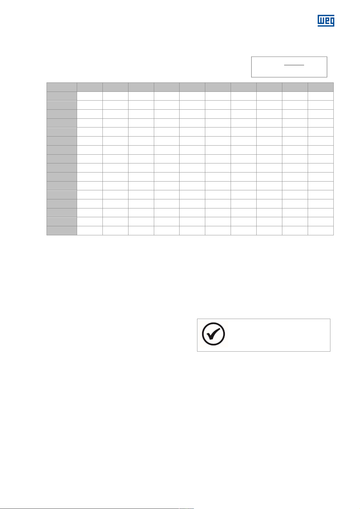
4.5.5 Temperature and ohmic resistance of the PT100 thermoresistance
Table 4.6 shows the temperature as a function of the ohmic resistance measured across PT100 RTDs.
º C 0 1 2 3 4 5 6 7 8 9
0 100.00 100.39 100.78 101.17 101.56 101.95 102.34 102.73 103.12 103.51
10 103.90 104.29 104.68 105.07 105.46 105.95 106.24 106.63 107.02 107.40
20
30 111.67 112.06 112.45 112.83 113.22 113.61 113.99 114.38 114.77 115.15
40 115.54 115.93 116.31 116.70 117.08 117.47 117.85 118.24 118.62 119.01
50
60 123.24 123.62 124.01 124.39 124.77 125.16 125.54 125.92 126.31 126.69
70 127.07 127.45 127.84 128.22 128.60 128.98 129.37 129.75 130.13 130.51
80
90
100 138.50 138.88 139.26 139.64 140.02 140.39 140.77 141.15 141.53 141.91
110 142.29 142.66 143.04 143.42 143.80 144.17 144.55 144.93 145.31 145.68
120
130 149.82 150.20 150.57 150.95 151.33 151.70 152.08 152.45 152.83 153.20
140 153.58 153.95 154.32 154.70 155.07 155.45 155.82 156.19 156.57 156.94
150
107.79 108.18 108.57 108.96 109.35 109.73 110.12 110.51 110.90 111.28
119.40 119.78 120.16 120.55 120.93 121.32 121.70 122.09 122.47 122.86
130.89 131.27 131.66 132.04 132.42 132.80 133.18 133.56 133.94 134.32
134.70 135.08 135.46 135.84 136.22 136.60 136.98 137.36 137.74 138.12
146.06 146.44 146.81 147.19 147.57 147.94 148.32 148.70 149.07 149.45
157.31 157.69 158.06 158.43 158.81 159.18 159.55 159.93 160.30 160.67
4.5.6 Space heater
The motor is equipped with a space heater to prevent
internal water condensation during long periods out of
operation, it must be assured that the space heater is
energized shortly after turning the motor off, and that it is
de-energized before the motor is put into operation.
The values of the space heater supply voltage and power
are informed in the connection diagram and in the specific
plate affixed to the motor.
Table 4.6: Temperature X Resistance (Pt100)
4.5.7 Water leak sensor
The motor is supplied with a water leak optical sensor,
installed internally, which uses the detection system by
diffraction.
The optical sensor is connected to the activation relay
installed inside of the accessories terminal box and serves
to detect any water leaks from the cooling system into the
motor.
The details of this accessory are shown in CONNECTION
DIAGRAM supplied with the motor.
Formula: Ω - 100 = °C
0.386
NOTE
sensor is installed in the
lowest part of the motor.
4.5.8 Water temperature sensor
The temperature sensors installed at the water inlet and
outlet (if any) are used to monitor the water temperature.
The water inlet temperature is indicated in item 4.6.1.3
and on a specific plate of the cooling system fixed to the
motor frame.
14108242 Installation, operation and maintenance manual – Squirrel cage motor – WGM20 Line l 23
Page 24
www.weg.net
ATTENTION
Maximum
Maximum
400 57 4 6 0,7
450 79 4 6 0,7
500 100 4 6 0,7
560 100 4 6 0,7
ATTENTION
The cooling system protection devices must
The water inlet and outlet must not be
1
2
3
1
2
3
4.6 COOLING
Only the correct installation of the motor and of the cooling
system can ensure its continuous operation without
overheating.
4.6.1 Cooling system
The motor water jacket cooling (IC71W) is done by the
axial water flow along to the frame and the cyclically
internal air circulation.
With the motor running, the internal fan causes the air to
circulate internally and to pass through the cooling
channels around the frame, cooling the motor internal
parts.
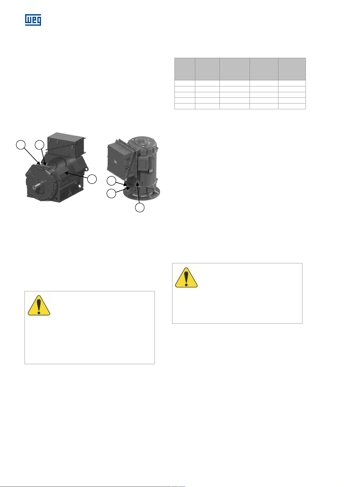
Figure 4.4: WGM20 motor cooling
Figure 4.4 legend:
1. Water inlet
2. Water outlet
3. Frame with internal channels for water circulation
The water circulating inside the frame dissipates the motor
internal heat.
The user must install the water supply system, complying
with the characteristics specified on the cooling system
nameplate fixed on motor frame.
4.6.1.1 Cooling system characteristics
Table 4.7: Cooling system technical characteristics (referential
Motor
Frame
355 50 4 6 0,7
Water
Flow
(l/min.)
values)
Operation
pressure
(bar)
system
pressure
(bar)
system
losses
(bar)
4.6.1.2 Cooling water characteristics
Make use of treated industrial water with the following
characteristics:
pH: 7.0 to 8.0;
Chlorides: < 50 ppm;
Sulphates: < 50 ppm;
Nitrates: < 10 ppm;
Iron content: < 0.3 ppm
Hardness < 150 ppm
Alkalinity < 200 ppm
Ammonia: < 10 ppm;
Conductivity: < 400 µS/cm;
Maximum size of charged particles in the water: ≤ 0.1
mm.
4.6.1.3 Cooling water temperature
In motors cooled by water jacket, the maximum
temperature difference between the inlet and outlet of
water must not exceed 10°C.
4.6.1.4 Protective devices
be monitored periodically.
In order to ensure proper operation and
prevent overheating of the motor, the data
of the cooling system informed on the
motor cooling system nameplate must be
strictly followed;
The water inlets and outlets must not be
obstructed, because it can cause
overheating or even lead to burning the
motor.
obstructed, because it can cause overheating
or even lead to burning the motor. For more
details, consult the motor DIMENSIONAL
DRAWING.
24 l Installation, operation and maintenance manual – Squirrel cage motor – WGM20 Line 14108242
Page 25
4.7 ELECTRICAL ASPECTS
The
ATTENTION
The stator terminal box allows for 180°
ATTENTION
ATTENTION
Place shims of different thicknesses between
The user is responsible for dimensioning and
1
2
3
4.7.1 Electrical connections
Before beginning the connection of the main cables and
those of the accessories, analyze carefully the electrical
CONNECTION DIAGRAM supplied with the motor. For the
electrical connection of auxiliary equipment, refer to their
specific manuals.
4.7.1.1 Main electrical connections
The location of stator terminal box is identified in the
specific motor DIMENSIONAL DRAWING.
The stator and rotor terminal identifications and their
corresponding connections are indicated in the specific
motor CONNECTION DIAGRAM.
Make sure the cross section and insulation of the
connection cables are suitable for the motor current and
voltage.
The motor must rotate in the rotation direction specified
on its nameplate and on the indicative arrow fixed on
motor drive end side.
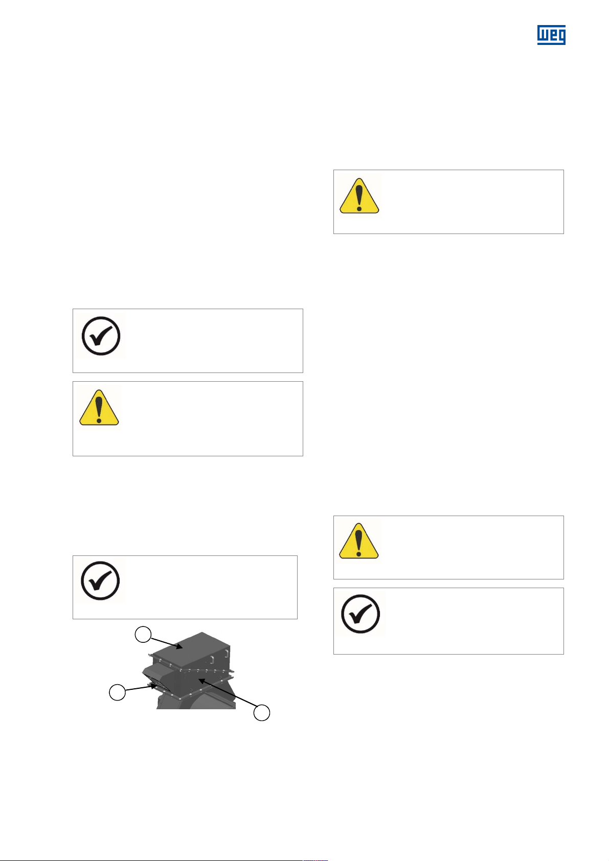
In order to connect the motor main power supply cables,
unscrew the cover (3) of the stator terminal box (1),
remove the cables inlet cover (2), cut the power supply
cables to the necessary length, strip the ends, place the
terminals on the connecting cables and secure them to
the stator connection bars.
Make sure that the connecting cables are correctly fixed
and close the
NOTE
rotation direction is, by convention,
determined looking to the shaft end at motor
drive end.
Before making the connections between the
motor and the power supply, it is necessary
to perform a careful measurement of the
winding insulation resistance.
terminal box with the cover (3).
NOTE
rotation in horizontal motors and 90° in
vertical motors.
www.weg.net
4.7.1.2 Grounding
The motor frame and the main terminal box must be
grounded before connecting the motor to the supply
system.
Connect the metallic sheath of the cables (if any) to the
common grounding conductor. Cut the grounding
conductor to the proper length and connect it to the
terminal in the terminal box and/or on the frame.
Fasten all connections firmly.
Do not use washers made of steel or other
materials with low electrical conductivity to
fasten the cable lugs.
4.7.2 Connection diagram
For the correct installation of the motor main power supply
circuit, refer to the motor specific CONNECTION
DIAGRAM.
4.7.3 Accessories connection diagram
For the correct installation of the accessories, refer to the
motor specific CONNECTION DIAGRAM.
4.8 MECHANICAL ASPECTS
4.8.1 Base
The base or structure where the motor will be installed
must be sufficiently rigid, flat, free of external vibration
and capable to withstand the mechanical loads to
which it will be submitted;
If the dimensioning of the base is not carefully executed,
this may cause vibration in the base, on the motor and
the driven machine;
The base structural design must be done based on the
dimensional drawing, on the information about base
mechanical loads, and on the motor anchoring method.
the motor supporting surfaces and the base
in order to allow a precise alignment.
NOTE
Figure 4.5: Stator terminal box
Figure 4.5 legend
1. Stator terminal box
2. Connection cables guide
3. Stator connection box cover
14108242 Installation, operation and maintenance manual – Squirrel cage motor – WGM20 Line l 25
building the base where the motor will be
installed.
Page 26
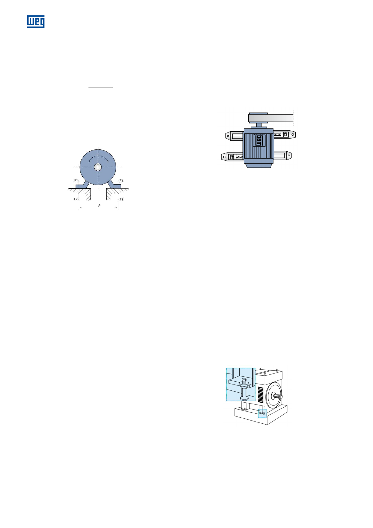
www.weg.net
4.8.2 Base loads
Based on Figure 4.6, base loads can be calculated by the
equations:
Where:
m - Motor mass (kg)
Cmax - Maximum torque (Nm)
A - Obtained from the motor dimensional drawing
(m)
1
2
F1 and F2 - Reaction of the feet on the base (N)
g - Acceleration of gravity (9.81m/s²)
gmF ++=
...5.0
gmF −+=
max)4(
C
...5.0
)(
A
max)4(
C
)(
A
The rail closer to the driving pulley must be mounted so
that the positioning bolt is placed between the motor and
the driven machine. The other rail must be mounted with
the bolt in the opposite position, as shown in Figure 4.7.
The motor is bolted on rails and positioned on the
foundation.
The driving pulley is then aligned so that its center and the
center of the driven pulley are in the same plane, and the
motor and machine shafts are perfectly parallel.
The belt must not be stretched too much. After the
alignment, the rails are fixed.
Figure 4.7: Sliding base
4.8.3.3 Metal base
The motor must rest evenly on the metal base in order to
Figure 4.6: Foundation loads
4.8.3 Base types
4.8.3.1 Concrete base
The type and size of the base, bolts and anchoring plates
depend on the motor size and type.
Example of base preparation:
Remove all the dirt from the foundation to ensure a
proper binding between the foundation blocks and the
mortar.
Fasten the foundation blocks to the motor feet using
bolts.
Use shims of different thicknesses (total thickness of
approximately 2 mm) between the motor feet and the
foundation surfaces in order to obtain a precise vertical
alignment.
In order to ensure the centralization of the bolts
regarding the foot holes, use a metallic or a cardboard
(prespan) sheet as bushing, making possible a precise
horizontal alignment later.
Place shims or leveling bolts under the foundation
blocks to ensure proper leveling and perfect alignment
of the motor with the driven machine. After the mortar
is applied, the alignment must be precisely controlled.
Occasional small corrections may be done with
washers or metal sheets or by readjusting the clearance
of the fastening bolts.
Tighten all the fastening bolts firmly. Make sure the
motor feet surfaces are supported evenly without
distorting the motor frame.
For precise fixation, introduce the tapered pins after
finishing the test.
4.8.3.2 Sliding base
In case of pulley drive, the motor must always be mounted
on a sliding base (rails), and the lower part of the belt must
be tightened.
26 l Installation, operation and maintenance manual – Squirrel cage motor – WGM20 Line 14108242
prevent deformations of the frame. Occasional errors in
the height of the surface that supports the motor feet can
be corrected with shims (a maximum height of 2 mm is
recommended).
Do not remove the machines from the common base to
align them. The base must be leveled on the foundation by
using spirit levels or other leveling devices.
When a metal base is used to align the height of the motor
shaft end with the machine shaft end, it must be leveled
on the concrete base.
After the base has been leveled, the anchor bolts
tightened and the couplings checked, then the metal base
and the anchor bolts are cemented.
4.8.3.4 Anchor bolts
Anchor bolts are devices to fasten the motors directly on
the foundation when the motors are applied with elastic
coupling. This coupling type is characterized by the
absence of loads on the bearings.
The anchor bolts must neither be painted, nor present
rust, since that impairs the adhesion to the concrete,
loosening them.
Figure 4.8: Anchor bolts
4.8.4 Natural frequency of the base
In order to ensure a safe operation, the motor must be
precisely aligned with the coupled equipment and both
must be properly balanced.
As a requirement, the motor installation base must be flat
and meet the requirements of DIN 4024-1 standard.
Page 27
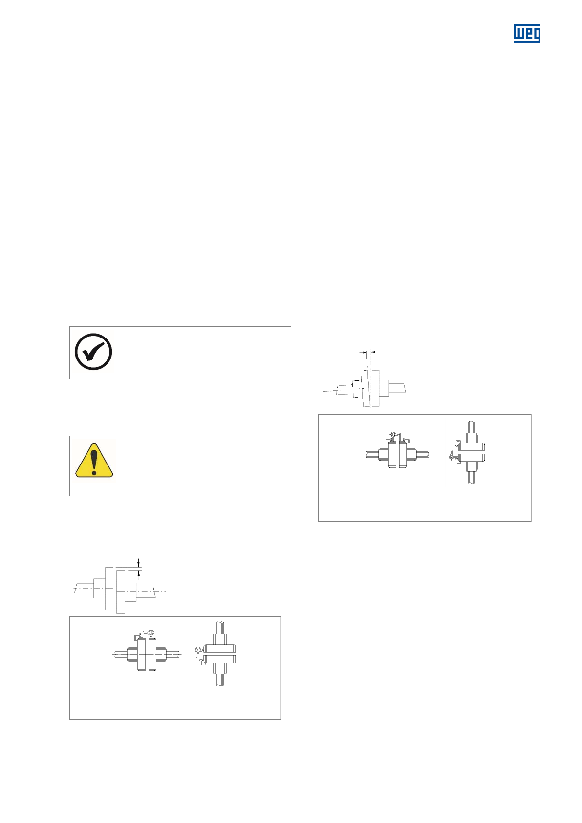
In order to verify if the criteria of the standard are being
At least 75% of the
ATTENTION
R
adial measurement
Paral
lel misalignment
Angular
misalignment
met, the following potential vibration excitation frequencies
generated by the motor and coupled machine must be
checked:
The motor rotation frequency;
The double of the rotation frequency;
The double of the motor electric frequency.
According to DIN 4024-1 standard, the natural
frequencies of the base or foundation must be away from
these potential excitation frequencies, as specified next:
The first natural frequency of the base or foundation
(first order natural frequency of the base) must be out of
the range from 0.8 to 1.25 times any of the potential
excitation frequencies above;
The other natural frequencies of the base or foundation
must be out of the range from 0.9 to 1.1 times any of
the potential excitation frequencies above.
4.8.5
Leveling
The motor must rest on a surface with flatness of up to
0.08 mm/m.
Verify whether the motor is perfectly leveled, both in the
vertical and horizontal planes. Make the proper
adjustments by placing shims under the motor. The motor
leveling must be checked with proper equipment.
NOTE
motor foot support
surfaces must rest on the motor base.
www.weg.net
Figure 4.9 shows the parallel misalignment of the two
shaft ends and the practical way to measure it by using
suitable dial gauges.
The measurement is performed in four points 90° away
from each other with the two half-couplings rotating
together in order to eliminate effects of support surface
irregularities on the dial gauge tip. Choosing the upper
vertical point as 0°, half of the difference between the dial
gauge measurements at the 0° and 180° points
represents the vertical coaxial error. In case of deviation, it
must be corrected by adding or removing leveling shims.
Half of the difference between the dial gauge
measurements at the 90º and 270º points represents the
horizontal coaxial error.
These measurements indicate when it is necessary to lift
or lower the motor, or move it to the right or to the left on
the drive end in order to eliminate the coaxial error.
Half of the maximum difference among the dial gauge
measurements in a complete rotation represents the
maximum eccentricity found.
The misalignment in a complete shaft rotation, with rigid or
semiflexible coupling, cannot exceed 0.03 mm.
When flexible couplings are used, greater values than
those indicated above are acceptable, provided that they
do not exceed the value allowed by the coupling
manufacturer.
It is recommended to keep a safety margin for these
values.
4.8.6 Alignment
The motor must be correctly aligned with the driven
machine.
Incorrect alignment can damage the
bearings, generate excessive vibration and
even break the shaft.
The alignment must be done according to the coupling
manufacturer recommendations.
The motor and driven machine shafts must be aligned in
the axial and radial directions, as shown in Figure 4.9 and
Figure 4.10.
Horizontal Mounting Vertical Mounting
Figure 4.9: Parallel alignment
Horizontal Mounting Vertical Mounting
Axial measurement
Figure 4.10: Angular alignment
Figure 4.10 shows the angular misalignment and a
practical form to measure it.
The measurement is done in four points 90° away from
each other, with the two half-couplings rotating together in
order to eliminate effects of support surface irregularities
on the dial gauge tip. Choosing the upper vertical point as
0°, half of the difference between the dial gauge
measurements at the 0° and 180° points represents the
vertical misalignment. In case of deviation, it must be
corrected by adding or removing alignment shims.
Half the difference between the dial gauge measurements
at the 90° and 270° points represents the horizontal
misalignment, which must be properly corrected by
displacing the motor in the lateral/angular direction.
Half of the maximum difference among the dial gauge
measurements in a complete rotation represents the
maximum angular misalignment found.
The misalignment in a complete shaft rotation, with rigid or
semiflexible coupling, cannot exceed 0.03 mm.
14108242 Installation, operation and maintenance manual – Squirrel cage motor – WGM20 Line l 27
Page 28
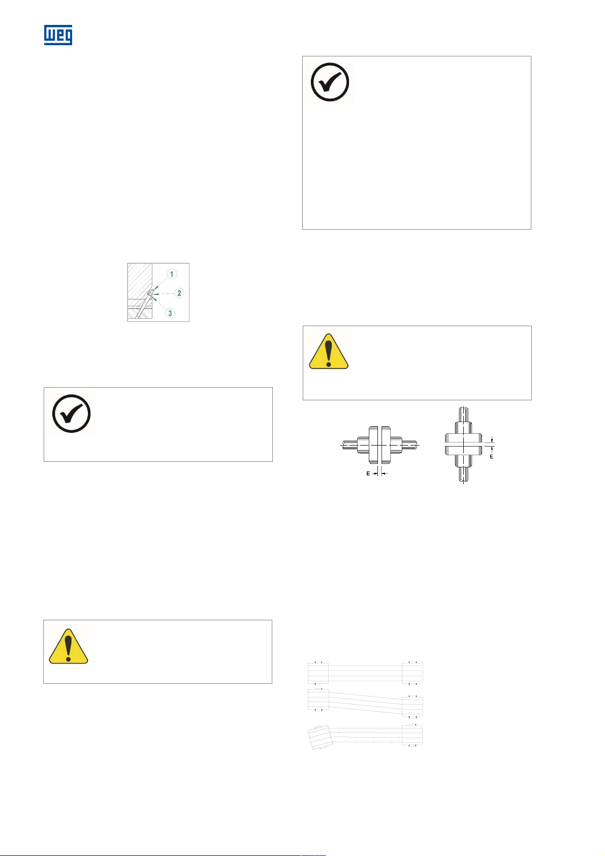
www.weg.net
ATTENTION
ins, nuts, washers and leveling shims
The user is responsible for the motor
ATTENTION
A
Corre
ct
Incorre
ct
When flexible couplings are used, greater values than
those indicated above are acceptable, provided that they
do not exceed the value allowed by the coupling
manufacturer.
It is recommended to keep a safety margin for these
values.
In the alignment/leveling, the influence of
the
temperature on the motor and the driven machine must
be taken into account. Different expansions of the parts
may change the alignment/leveling conditions during
operation.
4.8.7 Doweling
After aligning the set and having assured a perfect
alignment (both, hot and cold), the motor must be
doweled to the anchor plate or to the base, as shown in
Figure 4.11.
Figure 4.11 legend:
1. Dowel pin (optional supply)
2. Nut (optional supply)
3. Washer (optional supply)
Figure 4.11: Dowel pin set
NOTE
For the doweling, the motor has a pre-hole
with Ø9 mm, which must be first expanded
to Ø11.5 mm, and then reamed to Ø12 mm
with a taper of 1:50.
4.8.8 Couplings
Only proper couplings, which convey only torque without
generating transversal forces, must be used.
For both flexible and rigid couplings, the shaft centers of
the coupled machines must be in a single line.
Flexible couplings mitigate the effects of residual
misalignments and prevent transmission of vibration
between the coupled machines, which does not occur
when rigid couplings are used.
The coupling must be mounted or removed with the aid of
proper devices and never by means of rudimentary tools,
such as hammers, sledgehammers, etc.
Dowel p
may be supplied with the motor, when
requested in the purchase order.
NOTES
installation (unless otherwise specified by
commercial agreement).
WEG is not liable for damages to the motor,
associated equipment and installation
occurred because of:
Transmission of excessive vibration;
Poor installations;
Faulty alignment;
Improper storage conditions;
Noncompliance with the instructions
before start-up;
Incorrect electrical connections.
4.8.8.1 Direct coupling
Because of issues about cost, space economy, problems
with belt sliding and more safety against accidents, direct
coupling must be used whenever possible. Also, direct
coupling is preferable in case of transmission with
reduction gearing.
lign the shaft ends carefully, and, whenever
possible, use flexible coupling, leaving a
minimum clearance (E) of 3 mm between the
couplings, as shown in Figure 4.12.
Figure 4.12: Axial clearance of the coupling (E)
4.8.8.2 Gear coupling
Gear couplings badly aligned generate vibration in the
transmission itself and in the motor. Therefore, caution
must be taken so that the shafts be perfectly aligned,
rigorously parallel in case of spur gear transmissions and
in a correct angle in case of transmissions by bevel or
helical gears.
The gear teeth meshing can be controlled with the
insertion of a paper strip, on which the trace of all teeth
shows up after a gear turn.
4.8.8.3 Belt drive
Incorrect
Figure 4.13: Belt drive
28 l Installation, operation and maintenance manual – Squirrel cage motor – WGM20 Line 14108242
Page 29
When a reduction or increase in speed is required, the belt
ATTENTION
Always use properly balanced pulleys. Avoid
transmission is the most indicated.
In order to avoid unnecessary stress on the bearings, the
shafts and the pulleys must be perfectly aligned.
Belts that operate obliquely transmit alternating jolts to the
rotor and will be able to damage the bearings.
Belt slippage can be prevented by applying a resin like
material, such as pitch for instance.
The belt tension must be just enough to prevent slippage
during operation.
NOTE
Belts too tensioned increase the load on the
shaft end, causing vibration and fatigue, or
even the break of the shaft.
Avoid using too small pulleys, since they cause flexion of
the motor shaft because of the belt traction force that,
which increases as the diameter of the pulley decreases.
Consult WEG for the correct sizing of the
pulley.
NOTE
extra key lengths, because they increase the
unbalancing mass and increase the motor
vibration.
www.weg.net
14108242 Installation, operation and maintenance manual – Squirrel cage motor – WGM20 Line l 29
Page 30
www.weg.net
5 STARTING
5.1 DIRECT ON-LINE STARTING
It is the simplest and most economically feasible method;
however, it must only be used when the starting current
does not affect the power grid.
Bear in mind that the starting current of motors may reach
6 to 7 times the rated current value. Therefore, it must be
ensured that this current (Ip) will not affect the supply of
other consumers because of the high voltage drop in the
power grid.
This requirement is met in one of the three situations:
a) When the power grid is "strong" enough and the
motor current is negligible in relation to the grid
capacity.
b) The motor is always started without load, which
reduces the starting time and, in turn, the duration of
the starting current and the momentary voltage drop,
which is acceptable for the other consumers of the
grid;
c) When DOL starting is duly authorized by the local
electric utility company.
When the motor starting current is high, the following
detrimental consequences may occur:
a) The high voltage drop in the power supply system may
cause interference in equipment installed in this
system;
b) The protection system (cables, contactors) must be
oversized, increasing the installation costs.
30 l Installation, operation and maintenance manual – Squirrel cage motor – WGM20 Line 14108242
NOTE
In some cases, there is an imposition of the
electric utility companies that limits the
voltage drop of the grid.
5.2 DIRECT ONLINE STARTING
FREQUENCY
Since induction motors have a high starting current, the
time spent to accelerate loads with high inertia results in a
quick rise of the motor temperature. If the intervals
between successive starts are too short, the temperature
of the windings will rise quickly, reducing their useful life or
even burning them. The NBR 17094 and IEC60034-1
standards establishes a minimum starting duty to which
the motors must be able to comply:
a) Two successive starts: the first one with the motor
cold, i.e., with its windings at ambient temperature,
and the second one right afterwards, but only after
the motor has decelerated to a full stop;
b) One start with the motor hot, i.e., with the windings at
continuous duty temperature.
The first condition simulates the case in which the first
motor start is aborted, for instance, by the trip of the
motor protection, when a second motor start is permitted
right afterwards.
The second condition simulates the case of an accidental
motor shutdown under normal operation, for instance, by
power outage, when the motor restart is allowed right after
the power is reestablished.
NOTE
Special starting conditions must be checked
in the specific motor documentation before
starting the procedure.
5.3 LOCKED ROTOR CURRENT
The motor nameplate indicates the value of I
the relation between the starting current and the rated
current of the motor.
, which is
P/In
5.4 STARTING WITH REDUCED
CURRENT
If direct online starting is not possible, the following
starting systems can be used in order to reduce the motor
starting current.
Star-delta starter;
Series-parallel starter;
Autotransformer starter;
Static starter or soft-starter;
Frequency inverter.
Page 31
www.weg.net
ATTENTION
ATTENTION
6 COMMISSIONING
When the motor is started for the first time or after a prolonged standstill, several aspects must be considered besides the
regular operation procedures.
Avoid any contact with electric circuits;
Even low-voltage circuits may be life threatening;
In any electromagnetic circuit, overvoltages may occur under certain operating conditions;
Do not open an electromagnetic circuit suddenly, because the presence of an inductive discharge voltage
may break the insulation or injure the operator;
In order to open those circuits, disconnect switches or circuit breakers must be used.
6.1 PRELIMINARY INSPECTION
Before the first motor start or after long periods out of
operation, the following items must be inspected:
1. Check if all the motor fastening bolts are tightened;
2. Measure the winding insulation resistances, making
sure they are within the specified values;
3. Check if the motor is clean and if the packages,
measuring instruments and alignment devices were
removed from the motor operating area;
4. Check if coupling connecting components are in
perfect operating conditions, duly tightened and
greased, where necessary;
5. Check if the motor is correctly aligned;
6. Check if the bearings are properly lubricated. The
lubricant must be of the type specified on the
nameplate;
7. Inspect connections and parameterization of
accessories and protections;
8. Check if all electrical connections comply with the
motor connection diagram;
9. The cables connected to the stator and rotor main
terminals must be properly tightened in order to
prevent their short-circuit or loosening;
10. The terminal box covers must be correctly fastened;
11. Inspect the operation of the motor cooling water
supply system;
12. Motor air inlets and outlets must be unobstructed;
13. The moving parts of the motor must be protected to
prevent accidents;
14. Check if the power supply voltage and frequency
comply with the data on the motor nameplate;
6.2 FIRST STARTING
After all preliminary inspections have been carried out
proceed according to the directions presented next in
order to perform the first start of the uncoupled motor:
1. Turn off the space heaters;
2. Set the protections in the control panel;
3. Turn ON the water cooling system, checking the
necessary flow and pressure, and the temperature of
the cooling water;
4. Rotate the motor shaft slowly in order to check that no
part is being dragged or any abnormal noises are
occurring;
5. Start the motor with no load, making sure that it
bearing temperature indicates lubrication or friction
surface abnormality;
8. Monitor the bearing temperatures and the vibration
levels. If there is a significant variation of any value,
interrupt the motor starting, identify possible causes
and make the necessary corrections;
9. When the bearing temperatures stabilize, it is possible
to proceed to the other motor operation steps.
The noncompliance with the procedures
described in section 6.2 may impair the
motor performance, cause damages and
even lead to its burnout, voiding the
warranty.
6.3 OPERATION
The operating procedures vary considerably depending on
the motor application and the type of control equipment
used.
Only the general procedures are described in this manual.
For the control system operating procedures, refer to the
specific manual of this equipment.
6.3.1 General
After a first successful starting test, couple the motor to
the driven load, and then the starting procedure can be
reinitiated, as follows:
Start the motor coupled to the load until its temperature
stabilizes and check for unusual noises, abnormal
vibrations or excessive heating. If significant vibration
variations occur regarding the initial operation condition
until the condition after reaching thermal stability, then it
is necessary to check the alignment and the leveling.
Measure the current consumption and compare it to
the value given on the nameplate.
In continuous duty, without load variation, the measured
current must not exceed the value indicated on the
nameplate multiplied by the service factor;
All the instruments and devices for measurement and
control must be permanently monitored to detect
occasional alterations, determine their causes and
make the proper corrections.
rotates smoothly without strange noises;
6. Check the rotation direction with the motor uncoupled
from the load. In order to invert the rotation direction,
just invert the connection of any two phases;
7. Keep the motor rotating at rated speed and write
down the bearing temperatures at 1-minute intervals
until they become constant. Any sudden increase in
14108242 Installation, operation and maintenance manual – Squirrel cage motor – WGM20 Line l 31
Page 32
www.weg.net
ATTENTION
The motor cannot be operated without water
Vibration Levels (mm/s RMS)
Alarm 4.5 4.5 5.5
Alarm 3.5 4.5 5.5
ATTENTION
its
ATTENTION
The terminal boxes of motors equipped with
6.3.2 Temperatures
The temperatures of the bearings, stator winding and
cooling system must be monitored while the motor is
operating.
These temperatures must stabilize within 4 to 8 hours of
operation.
The stator winding temperature depends on the
machine load; therefore, the driven load must also be
monitored during the motor.
6.3.3 Bearings
The system start, as well as the first hours of operation,
must be monitored carefully.
During the first starting, it is important to pay attention
to unusual vibrations or noises; If the bearing is not
working silently and smoothly, shut the motor down,
identify de cause and correct it;
In case of overheating, the motor must be shut down
mmediately for the inspection of bearings and
i
temperature sensors, and the correction of possible
causes;
After the bearing temperatures stabilize, check if there
are no leaks through the plugs, gaskets or shaft end.
6.3.4 Cooling system
in the cooling system.
Adjust the water flow and pressure, as indicated on the
plate affixed to the motor;
For operation control purposes, it is recommended that
the cooling water temperatures at the inlet and outlet as
well as the differential pressure at the water inlet and
outlet be measured and recorded periodically;
These values must be periodically compared to the
riginal value, and an increase in the pressure
o
differential or a water temperature rise indicates the
need for cleaning the motor water circuit.
6.3.5 Vibration
The motors are balanced at the factory in compliance with
the vibration limits established by IEC60034-14, NEMA
MG1 – Part 7 and NBR 11390 standards (except when
the purchase contract specifies different values).
The vibration measurements are carried out on the NDE
and DE bearings, in the vertical, horizontal and axial
directions. When the customer sends the half coupling to
WEG, the motor is balanced with the half coupling
mounted on the shaft. Otherwise, according to the
standards above, the motor is balanced with half-key (i.e.,
the key slot is filled with a bar of the same width, thickness
and height of the key slot during the balancing operation).
The maximum vibration levels attended by WEG for
motors in operation are informed in Table 6.1. These
values are generic and for guidance, and the specific
application conditions must always be taken into account:
Table 6.1: Vibration (RMS)
Rated speed
(rpm)
600 ≤ n ≤ 1800
1800 < n ≤ 3600
Frame < 355 355 to 560 > 630
Tripping 7.0 7.0 8.0
Tripping 5.5 6.5 7.5
The main vibration causes are:
Misalignment between the motor and the driven
equipment;
Improper fastening of the motor to the base, with
“loose shims” under one or more motor feet, and loose
fastening bolts;
Improper or insufficiently rigid base;
External vibrations proceeding from other equipment.
Operating the motor with vibration levels
above the values contained in may impair
useful life and/or performance.
6.3.6 Shutdown
In order to shut down the motor, proceed as follows:
Reduce the load of the driven equipment, if possible;
Open the main circuit breaker.
After the motor stops completely:
Shut down the motor cooling water supply system;
Switch on the space heaters. They must be kept ON
until the next motor operation.
DANGER
Even after switching the motor off, while the
rotor is rotating, there is danger to life by
touching any of the motor active parts.
capacitors must not be opened before the
discharge time.
Discharge time of the capacitors: five
minutes after shutting down the motor.
32 l Installation, operation and maintenance manual – Squirrel cage motor – WGM20 Line 14108242
Page 33
7 MAINTENANCE
ATTENTION
The frequency of such inspections depends
7.1 GENERAL
A proper maintenance program for electric motors
includes the following recommendations:
Keep the motor and the associated equipment clean;
Measure the winding insulation resistance periodically;
Measure the temperature of windings, bearings and
cooling system periodically;
Check the wear, operation of the lubrication system
and useful life of the bearings;
Measure the motor vibration levels;
Inspect the cooling system;
Inspect associated equipment;
Inspect all the motor accessories, protections and
onnections, ensuring that they are operating properly;
c
Noncompliance with the recommendations
of item 7.1 may cause undesired stoppages
of the equipment.
on the local application conditions.
Every time that it becomes necessary to
transport the motor, the shaft must be
properly locked to prevent damages to the
bearings. Use the device supplied with the
motor to lock the shaft.
If the motor requires reconditioning or
replacement of any damaged part, consult
WEG.
7.2 GENERAL CLEANING
Keep the frame clean, without external accumulation
oil or dust, in order to facilitate the heat exchange with
the environment;
The inside of the motor must also be kept clean, free
of dust, debris and oils;
For cleaning, use brushes or clean cotton cloths. If the
dust is not abrasive, the cleaning must be done with
an industrial vacuum cleaner, “aspiring” the dirt from
the fan cover and the dust accumulated on the fan
blades and on the frame;
Debris impregnated with oil or moisture can be
removed with a cloth soaked in appropriate solvents;
Clean the terminal boxes when necessary. Terminals
and connectors must be kept clean, free of rust and in
perfect operating conditions. Avoid the presence of
grease or verdigris in the connection parts.
of
www.weg.net
7.3 WINDING INSPECTIONS
Yearly, the windings must be submitted to a complete
visual inspection, recording and repairing all and every
damage or defect observed.
The winding insulation resistance measurements must be
done at regular intervals, especially during humid weather
and after prolonged motor stoppages.
Low values or sudden variations in the insulation
resistance must be investigated.
The windings must be submitted to complete visual
inspections at frequent intervals, recording and repairing
all and every damage or defect observed.
The winding insulation resistance can be increased up to
an adequate value in the points where it is low (as a result
of excessive dust and moisture) by means of the dust
removal and by drying the winding moisture.
7.4 WINDING CLEANING
In order to obtain a more satisfactory operation and a
longer useful life of the insulated windings, it is
recommended to keep them free of dirt, oil, metal dust,
contaminants, etc.
Therefore, it is necessary to inspect and clean the
windings periodically, according to the recommendations
of the "Maintenance Plan" of this manual. If
reimpregnation is necessary, consult WEG.
The windings may be cleaned with an industrial vacuum
cleaner with a non-metallic crevice tool or just a dry cloth.
For extreme dirt conditions, it may be necessary to use a
proper liquid solvent for cleaning. This cleaning must be
quick to prevent prolonged exposure of the windings to
the solvent effects.
After being cleaned with solvents, the windings must be
completely dried.
Measure the insulation resistance and the polarization
index in order to assess the winding insulation conditions.
Winding drying time after cleaning varies depending on
the weather conditions such as temperature, humidity,
etc.
7.4.1 Inspections
The following inspections must be carried out after the
windings are carefully cleaned:
Check the insulations of the winding and connections;
Check if spacers, bindings, slot wedges, bandages
and supports are properly fixed;
Check for breaks, faulty welds, short-circuit betwee
turns and against the frame in the coils and
connections. In case any fault is detected, consult
WEG.
Ensure that all cables are properly connected and th
terminal fixation components are duly tightened.
Retighten, if necessary.
DANGER
Most solvents currently used are highly
toxic and/or flammable.
Solvents must not be used in the straight
parts of the coils of high-voltage motors,
because they may affect the protection
against corona effect.
n
at
14108242 Installation, operation and maintenance manual – Squirrel cage motor – WGM20 Line l 33
Page 34
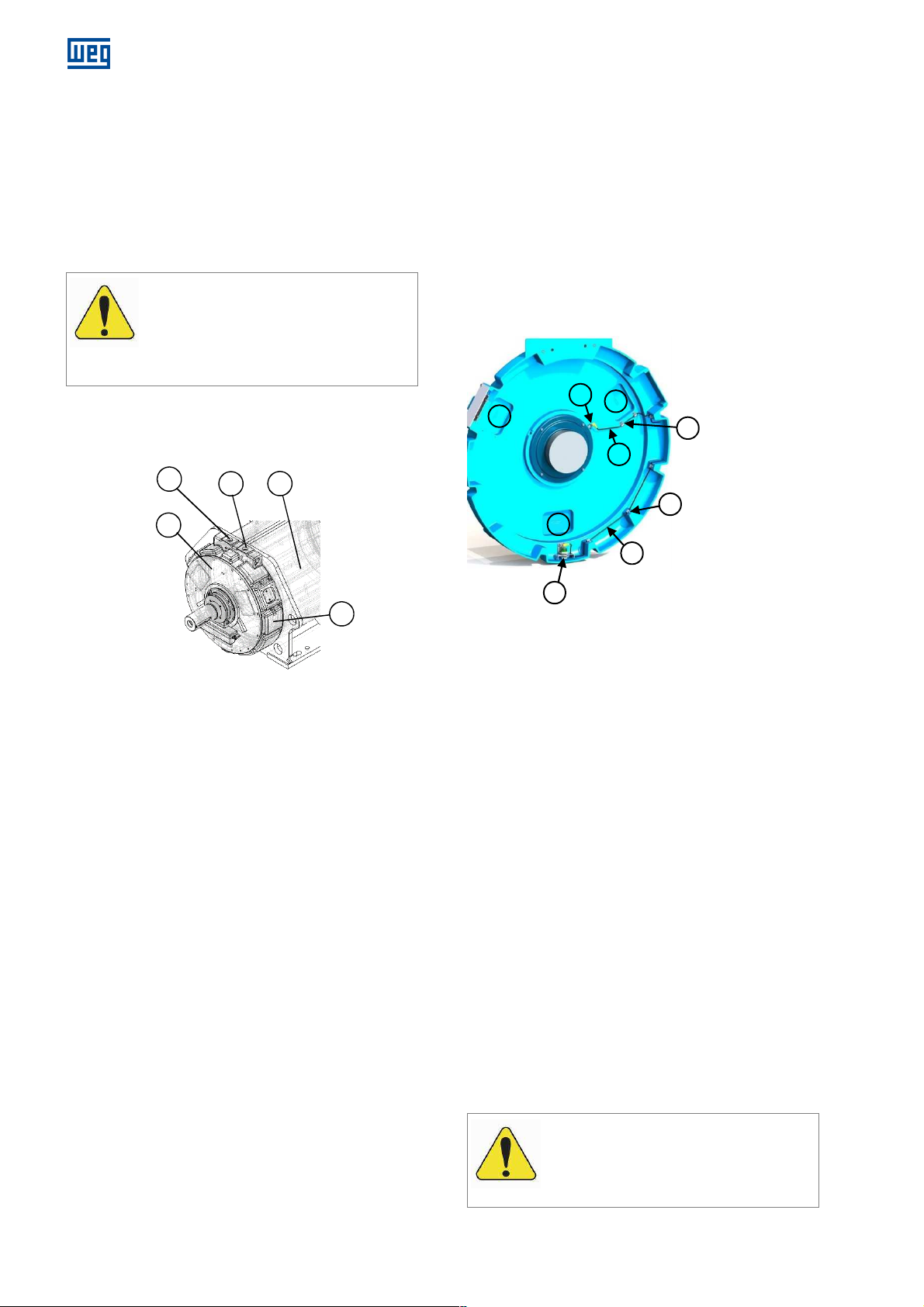
www.weg.net
ATTENTION
to operation,
ATENTION
from the
1
2
3
4
5
4
1
2
5
1
1
2
3
5
7.4.2 Reimpregnation
If any layer of resin on the windings is damaged during
cleaning or inspection, such parts must be corrected with
adequate material (in this case, consult WEG).
7.4.3 Insulation Resistance
The insulation resistance must be measured after the
completion of all of the maintenance procedures.
Before putting the motor back in
it is essential to measure the winding
insulation resistance and ensure that the
measured values meet the specifications.
7.5.1 Cleaning
In normal situations, where all recommendations
regarding water quality, flow and pressure are met, there
is no need to clean the cooling channels.
If there is an increase in the pressure drop and/or an
increase in cooling water temperature, it indicates an
increase of scale formation in the channels, which over
time, can clog and impair the water circulation. In this
case, the cooling water channels must be cleaned.
To access the water circulation channels, the motor
covers and cooling heads must be disassembled.
7.5.1.1 Motor end shield disassembly
7.5 COOLING SYSTEM
MAINTENANCE
Figure 7.1: Cooling system
Figure 7.1 legend:
1. Water inlet
2. Water outlet
3. Frame with water circulation channels
4. Motor end shield
5. Cooling head
The external part of the frame and the water
connections must be kept in good conditions;
If there is a freezing risk, antifreeze additive must be
used in the cooling water.
Add additives to the cooling water in proper quantities
for protection against corrosion and algae growth;
The type and amount of additives used must be
specified by the manufacturer of these additives and in
accordance with the environmental conditions where
the motor is installed.
34 l Installation, operation and maintenance manual – Squirrel cage motor – WGM20 Line 14108242
.
Figure 7.2: Motor end shield (internal view)
Figure 7.2 legend:
1. Inspection windows
2. Wire clamps
3. Bearing temperature sensor
4. Water leakage sensor
5. Accessories connecting cables
Before the motor end shield disassembling:
Remove the water from the motor frame by
disconnecting the water supply hoses and injecting
compressed air into the water inlet hole until the water
into the frame is completely withdrawn;
Loosen the cables of the bearing temperature sensors
in the accessory connection box. The bearing
temperature sensors must be removed together with
the motor end shields.
Disassembling the motor end shields:
1. Remove the inspection windows located on the
motor covers and cooling heads;
2. Disconnect the threaded connection cables of the
accessories (Pt100 of water inlet and outlet, and
water leakage sensor);
3. Loosen the clamps located near to the inspection
windows to loosen the cables from the covers;
4. Disassemble the accessories located in the motor
outside, if any. (E.g. vibration sensor and grounding
brush).
5. Support the motor shaft to support the rotor weight;
6. Remove the front and rear end shields of the motor.
It is important to make sure that all
connecting cables have been loosed
end shields before removing them.
Page 35
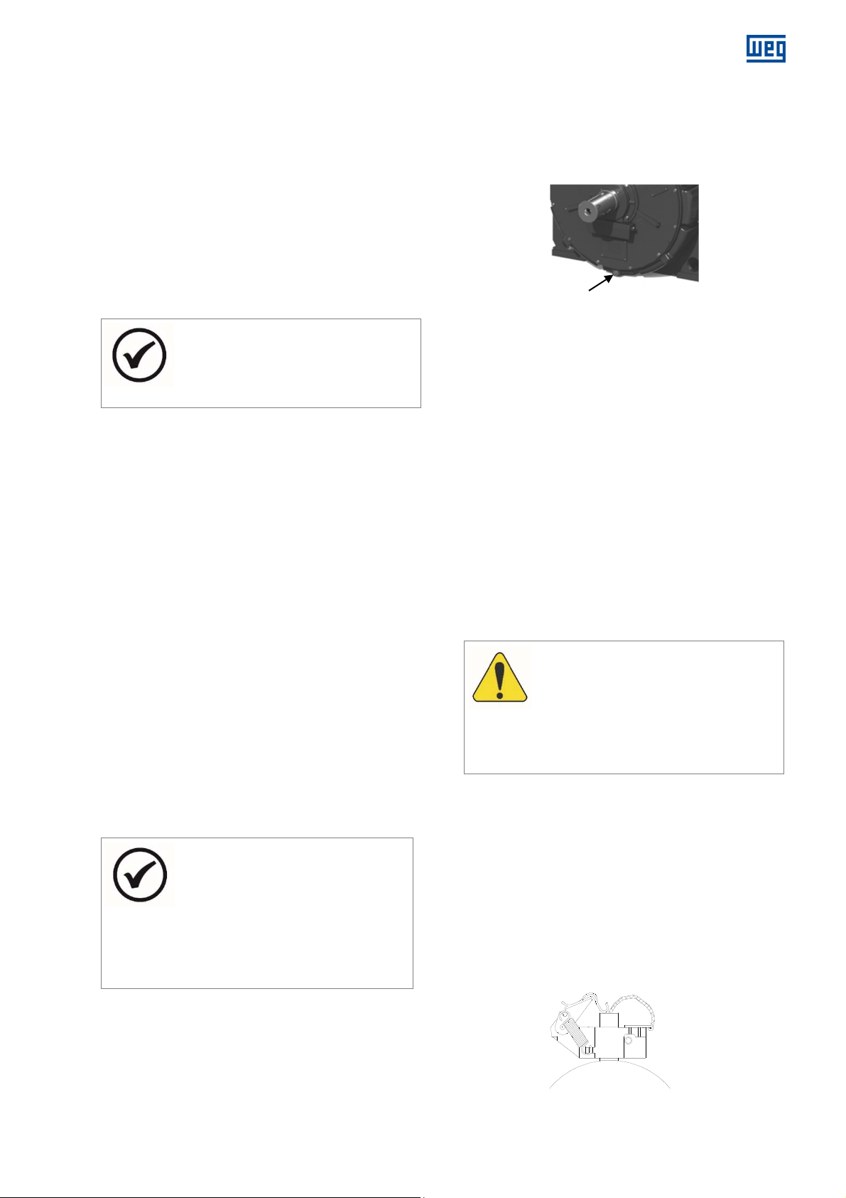
7.5.1.2 Cooling heads disassembly
To disassemble the cooling heads, first
The sealing gaskets should be assembled
annels. Anaerobic glue should not be
All screws
ATTENTION
water
Shaft
After removing the motor end shields, loosen all cables
fastened by clamps on the cooling heads.
Protect the motor internal parts before removing the
cooling heads to avoid wetting them, as there may be
water accumulated inside of the cooling heads channels.
1. Pull all accessories connecting cables;
2. Disconnect the connecting cables from the stator
connection box and pass them to inside the motor.
3. Apply compressed air on the cooling circuit to
eliminate any remaining water and prevent the motor
coil heads from being wetted;
4. Carefully remove the cooling heads so as not to
damage the gaskets.
NOTE
remove the motor end shields, to access the
stator and accessories connection cables.
7.5.1.3 Inspection and cleaning of water channels
The WGM20 motor allows full access to water circulation
channels.
1. After disassembling the motor covers and the cooling
heads, perform a detailed visual inspection on all water
channels to identify those that need cleaning;
2. Protect the motor internal parts (stator, rotor, shaft,
etc.)
3. Scrape the water channels to unclog the water
passage;
4. Remove debris from the channels;
5. Also, clean the inner part and the water inlet and outlet
of the cooling heads, if necessary.
7.5.1.4 End shields and cooling heads assembly
Before assembling the cooling heads, make sure that the
sealing gaskets, used between the cooling heads and the
motor frame, are in good condition of use, otherwise they
must be replaced.
To mount the motor covers and the cooling heads, follow
the procedure for disassembling these parts in the reverse
order.
NOTES
using only the grease to position it inside
the ch
used inside the channels.
that securing the cooling heads
must be tightened according to Table 8.1
or Table 8.2 and locked with chemical lock.
7.6 VIBRATION
Any evidence of increase in the unbalance or vibration of
the motor must be investigated immediately.
www.weg.net
7.7 MOTOR OUT OF OPERATION
When the motor is stopped, water may condense inside it.
In horizontal motors, this water must be removed through
the drain located at the lowest point of the cooling heads,
as shown in Figure 7.3.
Drain
Figure 7.3: Drain of horizontal motors
In vertical motors, the drain is located in the lower part of
the motor cooling head.
After the motor operation, if it remain stopped for long
term, the water inside the frame must be completely
drained, as follows:
In order to remove the water from the frame of
horizontal motors, disconnect the water supply hoses
and inject compressed air into one of the water inlets
until it drains out completely;
In order to remove the water from the frame of vertical
motors, disconnect the water supply hose and allow it
to drain completely through the lower opening;
For storage during long terms, follow the procedures
described in item 3.3.2 of this manual.
Turn ON the space heaters so that the temperature
inside the motor be kept slightly above the ambient
temperature, avoiding water condensation and
consequent drop of the winding insulation resistance
and oxidation of metallic parts.
If the motor remains stopped in
environments with negative temperatures,
the freezing of the motor cooling circuit
must be prevented. This can be done by
draining all the water from the frame or by
using antifreeze additives in the water;
7.8 SHAFT GROUNDING DEVICE
The rear end shield of the WGM20 motor is insulated. This
insulation in the end shield in relation to the rear bearing,
combined with the grounding brush installed in the front
bearing avoids the electric current circulation of the rotor
through the bearings, preventing the bearings from
prematurely failure due to wear caused by electric shocks.
The brush is put in contact with the shaft and connected
by a cable to the motor frame, which must be grounded.
Make sure that the brush holder fastening and its
connection to the frame have been made correctly.
14108242 Installation, operation and maintenance manual – Squirrel cage motor – WGM20 Line l 35
Figure 7.4: Shaft grounding brush
Page 36
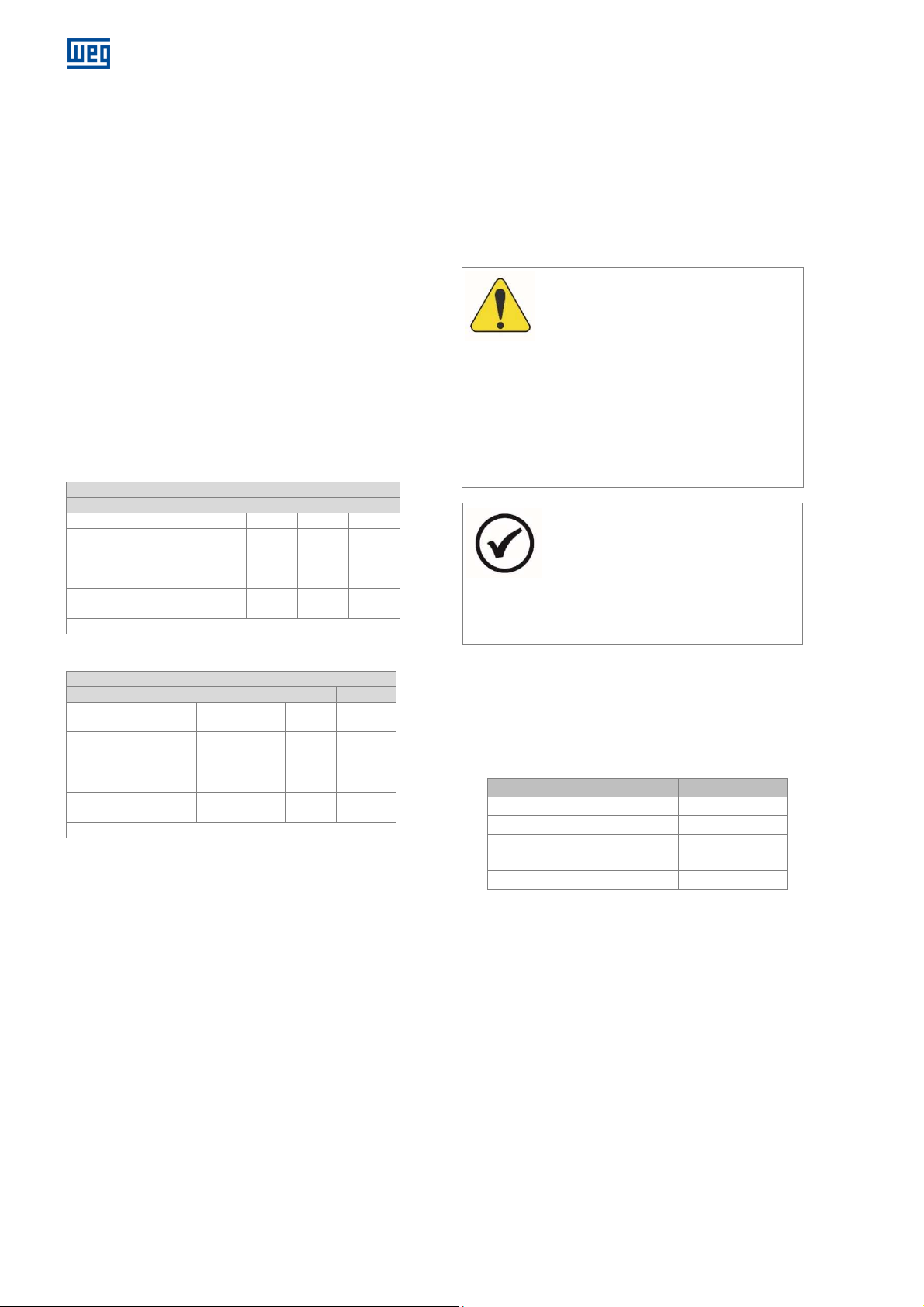
www.weg.net
Bearing data
– Horizontal motors
Front and Rear
Frame
355 400 450 500 560
Rolling
Grease
Lubrication
Grease
Polirex EM 103
Bearing data
– Vertical motors
Front Rear
355 to
Rolling
Grease
Lubrication
Grease
Polirex EM 103
ATTENTION
The injection of all the grease with the
The
Drying oil is used to protect the motor shaft against rust
during transportation. In order to ensure the proper
operation of the grounding brush, this oil, as well as any
residue between the shaft and the brush, must be
removed before starting the motor. The brush must be
constantly monitored during operation, and it must be
replaced by another one of the same quality (granulation)
at the end of its useful life.
7.9 ENCODER MAINTENANCE
The correct installation of the encoder (if any) is very
important for its operation. Both disassembly and
assembly must be done by skilled and trained personnel,
according to the procedures contained in the specific
manual of the equipment manufacturer.
If any further explanations are necessary, consult WEG.
7.10 BEARING MAINTENANCE
7.10.1 Bearing data
Table 7.1: Bearing data: horizontal motors
It is recommended to make the lubrication with the motor
in operation in order to ensure the renewal of the grease in
the rolling bearing housing.
If that is not possible due to the presence of rotating parts
near the grease nipple (pulleys, etc.) which may put the
operator at risk, follow the procedures below:
With the motor stopped, inject approximately half of
the
total intended amount of grease and operate the motor
for approximately one minute at full speed;
Stop the motor and inject the rest of the grease.
motor stopped may lead to the penetration
of part of the lubricant into the motor
through the internal seal of the rolling
bearing cap;
It is important to clean the grease nipples
prior to lubrication in order to prevent
foreign materials from being dragged into
the rolling bearing. For lubrication, use only
manual grease gun.
Bearing
quantity (g)
interval (h)
6222 6224 6228 6232 6232
38 43 52,5 69,6 69,6
4500 4500 4420 3420 3420
quantity (g)
interval (h)
Table 7.2: Bearing data - vertical motors
Frame 355 400 450 500
Bearing
6222 6224 6226 6232 7222
41 43 46 69,6 38
4500 4500 4500 3270 2240
500
7.10.2 Instructions for lubrication
The lubrication system was designed in such a way that
during the lubrication of the rolling bearings, all the old
grease is removed from the rolling bearing races and
expelled through a drain which enables the exit of the
grease, but prevents the ingress of dust or other harmful
contaminants.
This drain also prevents damage to the rolling bearings by
excessive lubrication.
NOTE
rolling bearing data, amount and type
of grease, and lubrication intervals are
informed in Table 7.1, Table 7.2 and on a
bearing nameplate fixed to the motor.
Check this information before performing
the lubrication.
The lubrication intervals informed consider the working
temperature of the rolling bearing of 70ºC;
Based on the operating temperature ranges listed in
Table 7.3, apply the following correction factors for the
rolling bearing lubrication intervals:
Table 7.3: Reduction factor for lubrication intervals
Bearing operating temperature Reduction factor
Below 60 ºC 1.59
Between 70 and 80 ºC 0.63
Between 80 and 90 ºC 0.40
Between 90 and 100 ºC 0.25
Between 100 and 110 ºC 0.16
7.10.3 Procedures for bearing lubrication
1. Clean with a cotton cloth around the hole of the
grease nipple;
2. With the rotor operating, inject the grease with a
manual grease gun until grease starts coming out from
the drain or until the proper amount of grease,
informed in Table 7.1 and Table 7.2 has been injected.
3. Keep the motor running long enough so that the
grease excess passes through the drain;
4. Inspect the bearing temperature to make sure there
was no significant change;
36 l Installation, operation and maintenance manual – Squirrel cage motor – WGM20 Line 14108242
Page 37
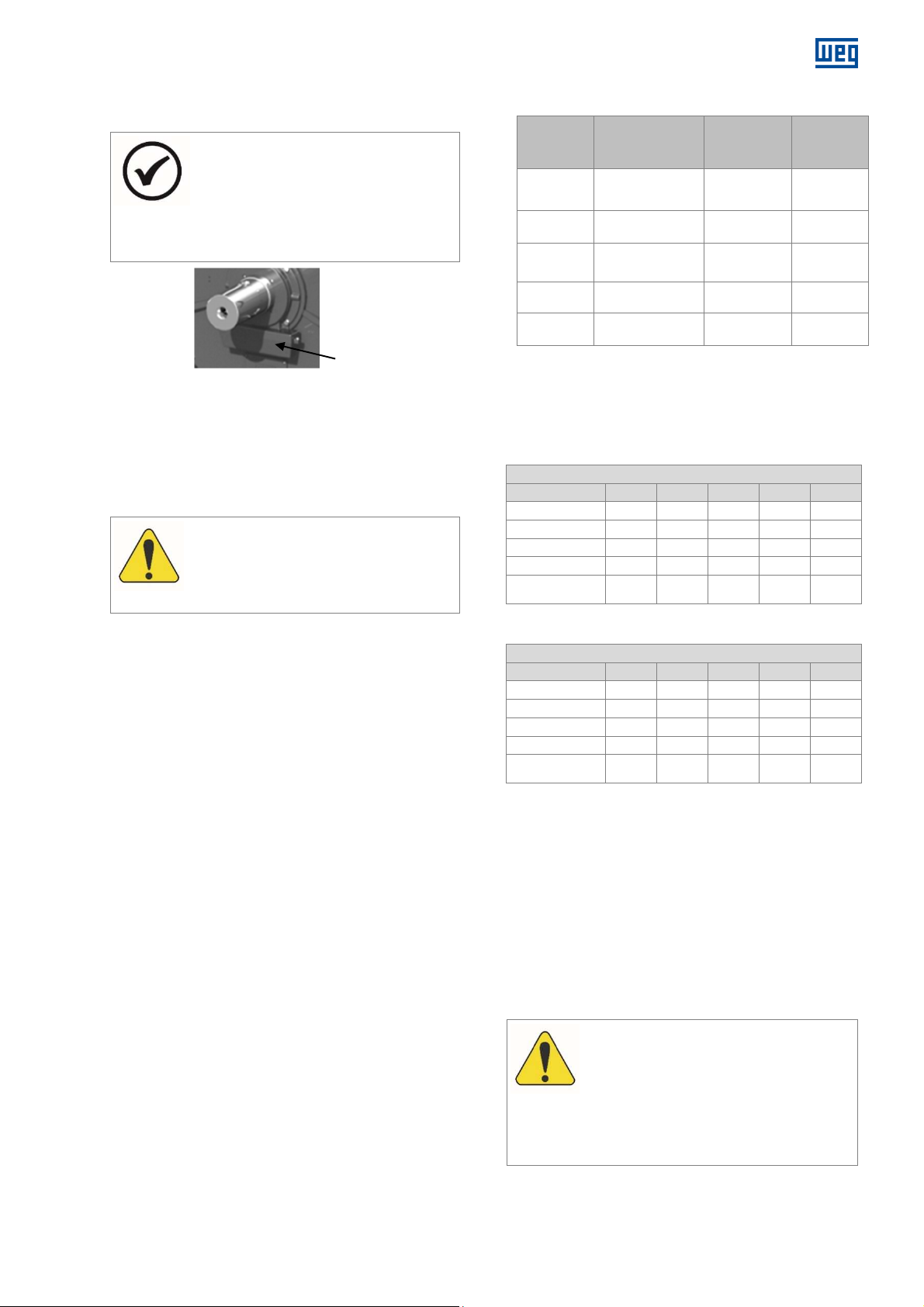
The excess of grease exits through the lower bearing drain
It is not necessary to remove old grease from
ATTENTION
Lubrax Industrial
Lubrax Industrial
ATTENTION
attempt to purge it. This
and deposits in the grease reservoir.
NOTE
the reservoir at each relubrication. When the
reservoir is full, disassemble it, discard the
old grease in an appropriate location and
reassemble it, as shown in Figure 7.5.
Grease reservoir
Figure 7.5: Grease reservoir
7.10.4 Type and amount of grease
The relubrication of the bearings must always be done
with the
original grease
, specified on the bearing
nameplate and in the documentation of the motor.
WEG does not recommend the use of
greases different from the motor original
grease.
It is important to perform a correct lubrication, i.e., to
apply the correct grease and in the proper quantity,
because either poor or excessive lubrication will damage
the rolling bearings.
Excessive amount of grease cause temperature increase,
due to the great resistance it offers to the movement of
the bearing rotating parts. Consequently, due to the
heating, the grease can completely lose its lubricating
characteristics.
7.10.5 Alternative greases
If it is not possible to use the original grease, alternative
greases listed in Table 7.4 can be used, under the
following conditions:
1. The motor speed must not exceed the limit speed of
the grease, according to the type of rolling bearing, as
informed in Table 7.5 and table 7.6;
2. The bearing lubrication interval must be corrected by
multiplying the interval informed on the bearing
nameplate by the multiplication factor informed in
Table 7.4;
3. Use the correct procedure to change the grease,
according to section 7.10.6 of this manual.
www.weg.net
Table 7.4: Options and characteristics of the alternative greases
Manufacturer
Exxon Mobil
Shell
Petrobras
Shell
SKF
for regular applications
Grease
UNIREX N3
(Lithium Complex
Soap)
ALVANIA RL3
(Lithium Soap)
LUBRAX
INDUSTRIAL GMA-2
(Lithium Soap)
STAMINA RL2
(Diurea Soap)
LGHP 2
(Polyurea Soap)
Constant
operating
temperature
(°C)
(-30 to +150) 0.90
(-30 to +120) 0.85
(0 to +130) 0.85
(-20 to +180) 0.94
(-40 to +150) 0.94
Multiplication
factor
The Table 7.5 and the Table 7.6 show the types of rolling
bearings for the horizontal and vertical motors, the amount
of grease and the rotation limit of use the optional
greases.
Table 7.5: Optional greases application - horizontal motors
GREASE LIMIT ROTATION [rpm] – Horizontal Motors
Rolling bearing
Stamina RL2
LGHP 2
Unirex N3
Alvania RL3
GMA-2
Table 7.6: Optional greases application - vertical motors
GREASE LIMIT ROTATION [rpm] – Vertical Motors
Rolling bearing
Stamina RL2
LGHP 2
Unirex N3
Alvania RL3
GMA-2
6222 6224 6228 6232 7222
1800 1800 1800 1800 1800
1800 1800 1800 1800 1800
1800 1800 1800 1500 1800
1800 1800 1800 1200 1800
1800 1800 1500 1200 1800
6222 6224 6226 6232 7222
1800 1800 1800 1800 1800
1800 1800 1800 1800 1800
1800 1800 1800 1800 1800
1800 1800 1800 1500 1800
1800 1800 1500 1200 1800
7.10.6 Procedure for changing the grease
In order to replace the
POLYREX EM103
of the alternative greases, the bearings must be opened to
remove the old grease and then filled with the new grease.
If it is not possible to open the bearings, the old grease
must be purged by applying new grease until it begins to
appear in the exit drawer with the motor running.
In order to replace the
STABURAGS N12MF
one of the alternative greases, you must first open the
bearings, completely remove the old grease, and then fill it
with new grease.
grease by one
grease by
Since there is no grease compatible with
STABURAGS N12MF
not be injected in the
procedure will not expel completely the old
grease and they will mix, which may cause
damage to the bearings.
, other grease must
14108242 Installation, operation and maintenance manual – Squirrel cage motor – WGM20 Line l 37
Page 38
www.weg.net
ATTENTION
or for
Constant
MOBILITH SHC
ATTENTION
ATEN
When the bearing is opened, inject the new
grease through the grease nipple to expel
the old grease found in the grease inlet
tube, and apply the new grease in the
rolling bearing, to the inner and outer
bearing caps, filling 3/4 of the empty
spaces. In case of double bearings (ball
bearing + roller bearing), also fill 3/4 of the
empty spaces between the intermediate
rings.
Never clean the rolling bearing with cottonbased cloths, because they may release
some lint, working as solid particles.
NOTE
WEG is not liable for the grease change
any damages arising from this change.
7.10.7 Low temperature greases
Table 7.7: Grease for application at low temperatures
Manufacturer
Exxon Mobil
Grease
100
(Lithium Soap and
Synthetic Oil)
operating
temperature
(°C)
(-50 to +150)
Application
Low
temperature
7.10.8 Grease compatibility
You can say that greases are compatible when the
properties of the mixture are within the property ranges of
the greases individually.
In general, greases with the same type of soap are
compatible; however, depending on the proportion of the
mixture, there might be incompatibility. Therefore, it is not
recommended to mix different types of grease without
consulting the grease supplier or WEG.
Some thickeners and basic oils cannot be mixed, because
they do not form a homogeneous mixture. In this case,
one cannot rule the possibility of hardening or softening of
the grease, or reduction of the dropping point of the
resulting mixture.
Greases with different types of base must
never be mixed.
For example: Lithium-based greases must
never be mixed with sodium or calciumbased greases.
7.10.9 Bearing disassembly
Before disassembling the bearing:
Remove the water from the cooling circuit, as described
in item 7.7 of this manual;
Place the motor in the horizontal position (vertical
machines);
Clean the bearing outside completely;
Remove the grounding brush (if any);
Loose the cables of the bearing temperature sensors
on the accessory connection box.
TTION
During the bearings disassembly, care must
be taken to avoid damage the balls, rollers or
shaft surface.
38 l Installation, operation and maintenance manual – Squirrel cage motor – WGM20 Line 14108242
Page 39
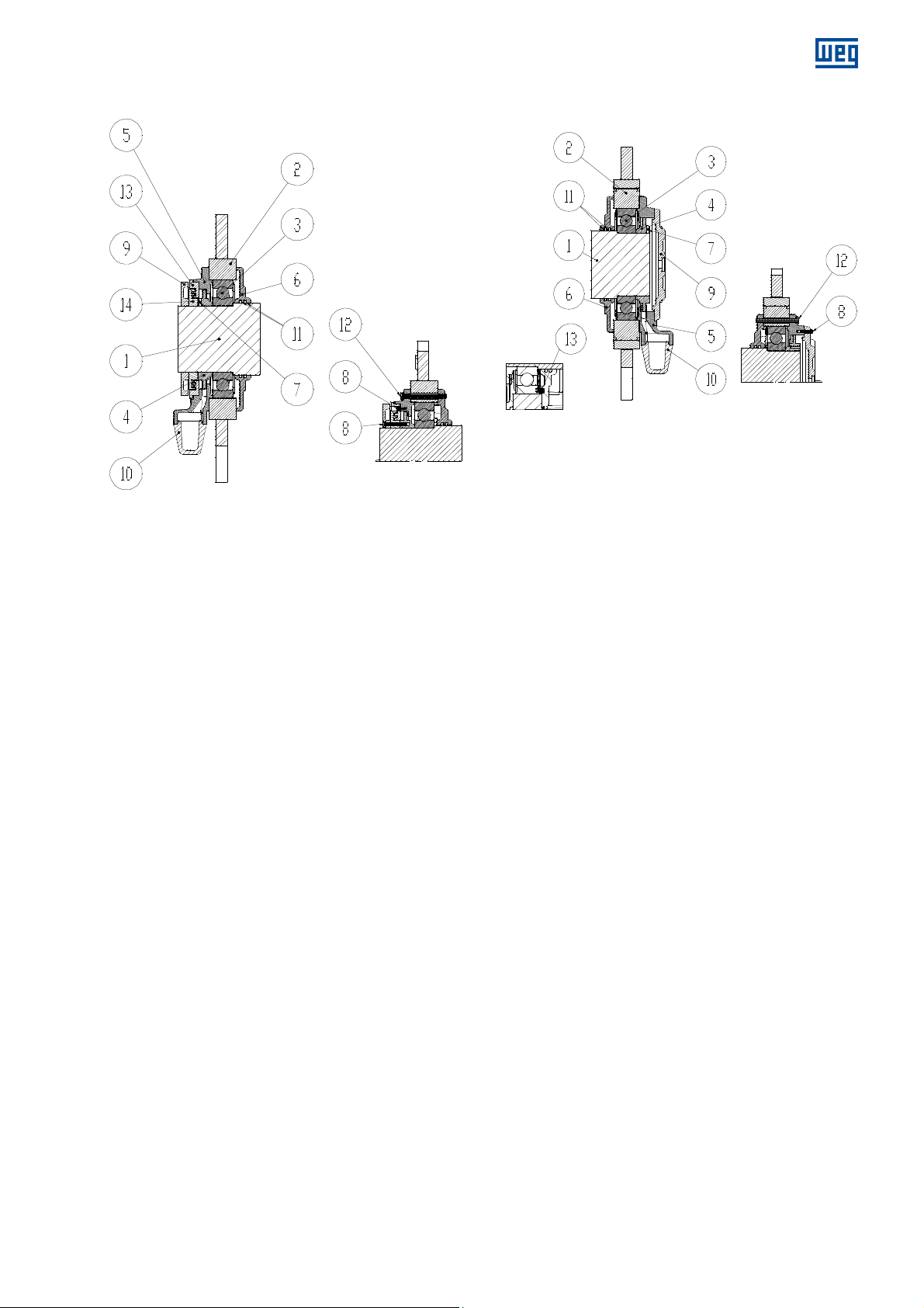
7.10.9.1 DE horizontal bearing disassembly
Figure 7.6: DE horizontal bearing
Figure 7.6 legend:
1. Shaft
2. DE end shield
3. Bearing
4. Grease flinger
5. External bearing cap
6. Internal bearing cap
7. Inner hexagon screw – with no head
8. Inner hexagon screw
9. Protection ring without labyrinth
10. Grease reservoir
11. Feltre
12. Hexagon head screw
13. Protection ring with labyrinth
14. Protection ring without bronze labyrinth
In order to disassemble the bearing, proceed according to
the following guidelines:
1. Remove the screws (8) and the protection rings (9, 13
and 14);
2. Remove the rings (12) that fasten the bearing internal
and external bearing caps;
3. Remove the external bearing cap (5);
4. Remove the screw (7) that fasten the grease flinger;
5. Remove the grease flinger (4);
6. Remove the DE end shield of the motor (2);
7. Remove the bearing (3);
8. Remove the internal bearing cap (6), if is necessary.
www.weg.net
7.10.9.2 NDE horizontal bearing disassembly
Figure 7.7 Legend:
1. Shaft
2. DE end shield
3. Bearing
4. Grease flinger
5. External bearing cap
6. Internal bearing cap
7. Inner hexagon screw – with no head
8. Inner hexagon screw
9. Protection ring without labyrinth
10. Grease reservoir
11. Feltre
12. Hexagon head screw
13. Compression spring
In order to disassemble the bearing, proceed according to
the following guidelines:
1. Remove the screws (8), and the protection ring (9);
2. Remove the rings (12) that fasten the bearing internal
and external bearing caps;
3. Remove the external bearing cap (5);
4. Remove the screw (7) that fasten the grease flinger;
5. Remove the grease flinger (4);
6. Remove the NDE end shield of the motor (2);
7. Remove the bearing (3);
8. Remove the internal bearing cap (6), if is necessary.
Figure 7.7: NDE horizontal bearing
14108242 Installation, operation and maintenance manual – Squirrel cage motor – WGM20 Line l 39
Page 40
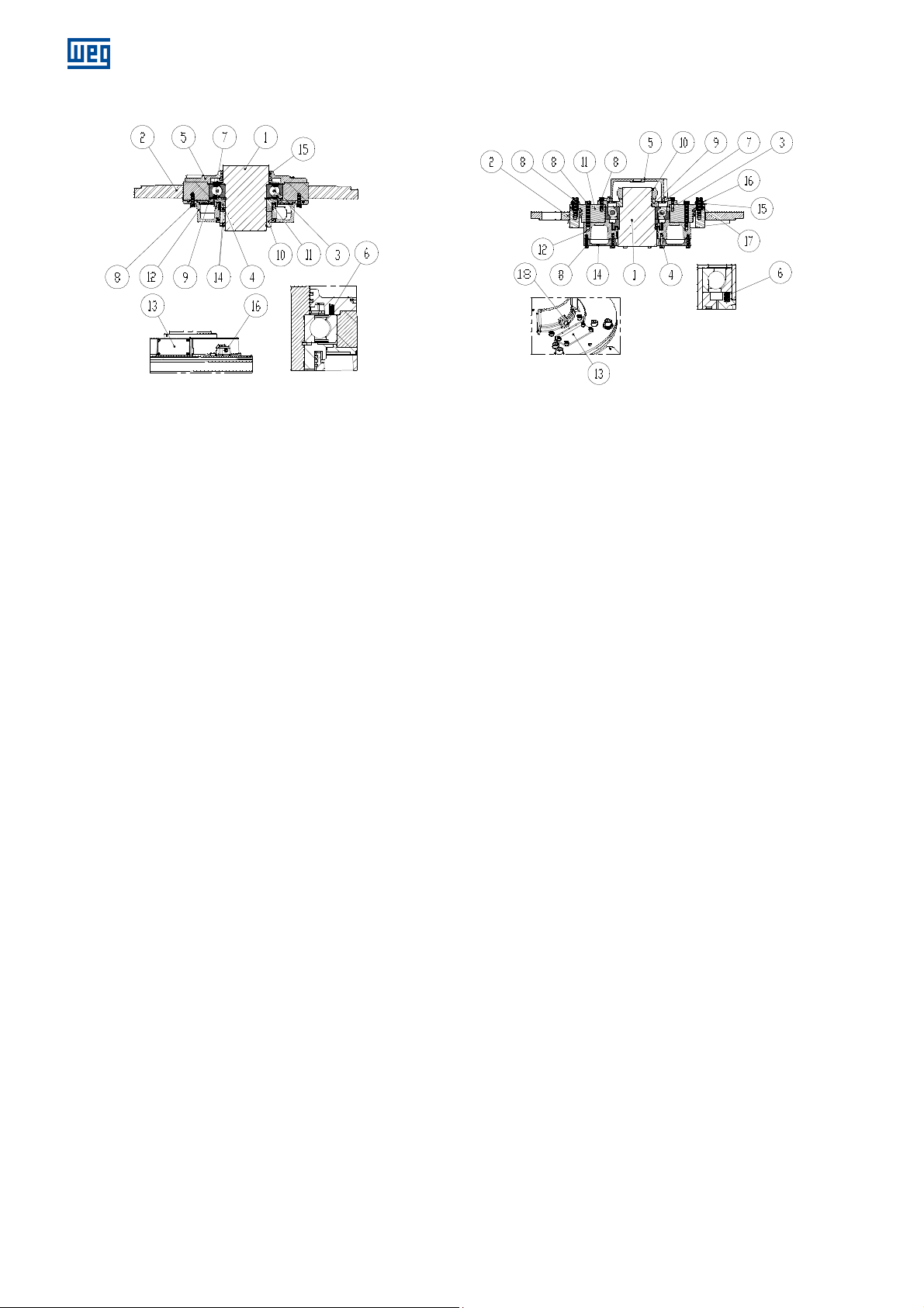
www.weg.net
7.10.9.3 DE vertical bearing disassembly
Figure 7.8 legend:
1. Shaft
2. DE end shield
3. Bearing
4. Grease slinger
5. Internal bearing cap
6. Compression spring
7. Grease retention disc
8. Inner hexagon screw
9. Intermediate ring
10. Bearing protection ring
11. Axial locking ring
12. Grease reservoir
13. Grease viewfinder cover
14. Inner hexagon screw – with no head
15. Feltre
16. Grease inlet
In order to disassemble the bearing, proceed according to
the following guidelines:
1. Place the motor in the horizontal position;
2. Remove the screws (14) and the bearing protection ring
(10);
3. Remove the screws (8) that fasten the grease reservoir;
4. Remove the grease reservoir (12), the grease slinger (4)
and the intermediate ring (9);
5. Remove the DE end shield (2);
6. Remove the axial locking ring (11)
7. Remove the bearing (3);
8. Remove the internal bearing cap (5), if is necessary.
Figure 7.8: DE vertical bearing
7.10.9.4 NDE vertical bearing disassembly
Figure 7.9: NDE vertical bearing
Figure 7.9 legend:
1. Shaft
2. NDE end shield
3. Bearing
4. Grease slinger
5. External bearing cap
6. Compression spring
7. Grease retention disc
8. Inner hexagon screw
9. Bearing protection ring – without labyrinth
10. KMT nut
11. Bearing hub
12. Grease reservoir
13. Grease viewfinder cover
14. Grease reservoir cover
15. Insulated washer
16. Flat washer
17. Insulated tube
18. Grease inlet
In order to disassemble the bearing, proceed according to
the following guidelines:
1. Support the motor shaft with a hydraulic jack;
2. Remove the screws (8) that fasten the external bearing
cap;
3. Remove the external bearing cap (5);
4. Remove the KMT nut (10), the bearing protection ring
(9) and the grease retention disc (7);
5. Remove the screws that fasten the bearing hub (11)
and remove it;
6. Remove the NDE end shield (2);
7. Move the grease reservoir (12) away from the bearing,
to provide space to set bearing removing device;
8. Remove the bearing (3);
9. Remove grease slinger (4) and grease reservoir (12), if
necessary.
40 l Installation, operation and maintenance manual – Squirrel cage motor – WGM20 Line 14108242
Page 41
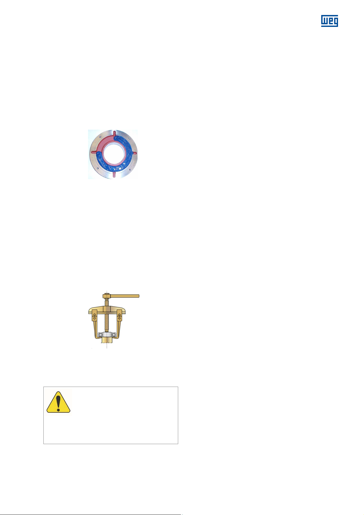
7.10.9.5 Bearing assembly
ATTENTION
The following temperatures must be set on
Alarm 110 ºC
The alarm temperature must be set 10 ºC
Clean the bearings completely and inspect the
disassembled parts and the inside of the bearing caps;
Make sure the rolling bearing, shaft and bearing cap
surfaces are perfectly smooth;
Fill up to ¾ of the inner and outer bearing cap deposits
with the recommended grease (Figure 7.10) and
lubricate the rolling bearing with enough grease before
assembling it;
Before assembling the rolling bearing on the shaft, heat
it up to a temperature between 50 ºC and 100 ºC;
For the complete assembly of the bearing, follow the
disassembly instructions in the reverse order.
Figure 7.10: External bearing cap
7.10.9.6 Bearing insulation
The motor has insulated NDE end shield and shaft
grounding brush to prevent the passage of electric current
through the bearings.
To replace these parts, it is recommended to use original
parts.
7.10.10 Rolling bearing replacement
The disassembly of rolling bearings must be done with an
appropriate tool (rolling bearing puller).
The arms of the puller must be placed on the lateral
surface of the bearing inner ring to be disassembled or on
an adjacent part.
Figure 7.11: Tool for rolling bearing extraction
7.10.11 Bearing protection
7.10.11.1 Protection settings
the bearing protection system:
above the operating temperature, not
exceeding the limit of 110 ºC.
– Trip 120 ºC
www.weg.net
14108242 Installation, operation and maintenance manual – Squirrel cage motor – WGM20 Line l 41
Page 42
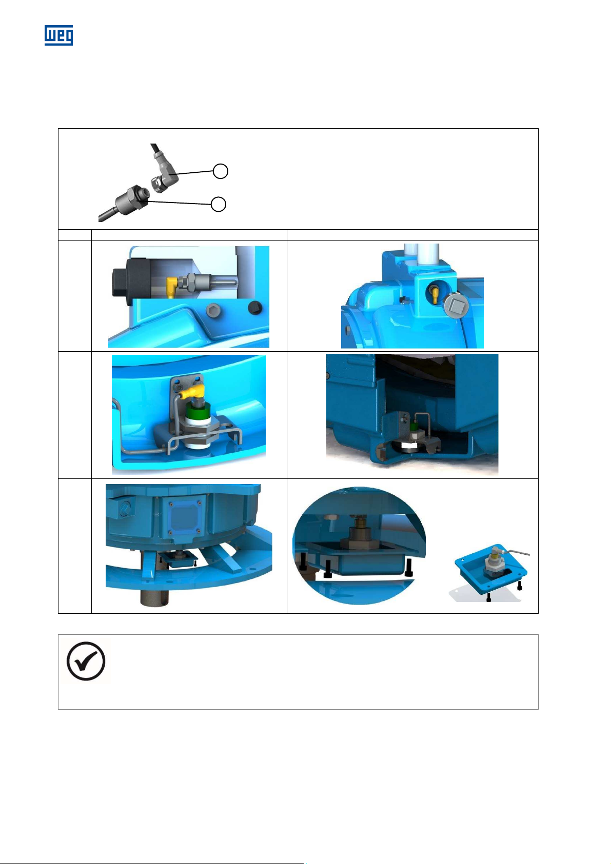
www.weg.net
Threaded
connection cable
Accessory location
Accessory d
isassembly
/ assembly
1
2
7.11 ACCESSORIES MAINTENANCE
The accessories shown in Table 7.8 have threaded connection cables and can be replaced without disconnecting the
connection cables in the terminal box.
Table 7.8: Accessories maintenance
1. Motor accessory
2. Accessory connection cable
Pt-100 of water inlet
and outlet
Water leakage sensor
Horizontal Motors
Water leakage sensor
Vertical Motors
42 l Installation, operation and maintenance manual – Squirrel cage motor – WGM20 Line 14108242
NOTES
The accessories are assembled and aligned with the inspection windows, allowing easy access for
assembly / disassembly;
It is not possible to replace the stator temperature sensors. The stator has reserve temperature sensors
to be used in case of failure of the sensors in operation.
Page 43
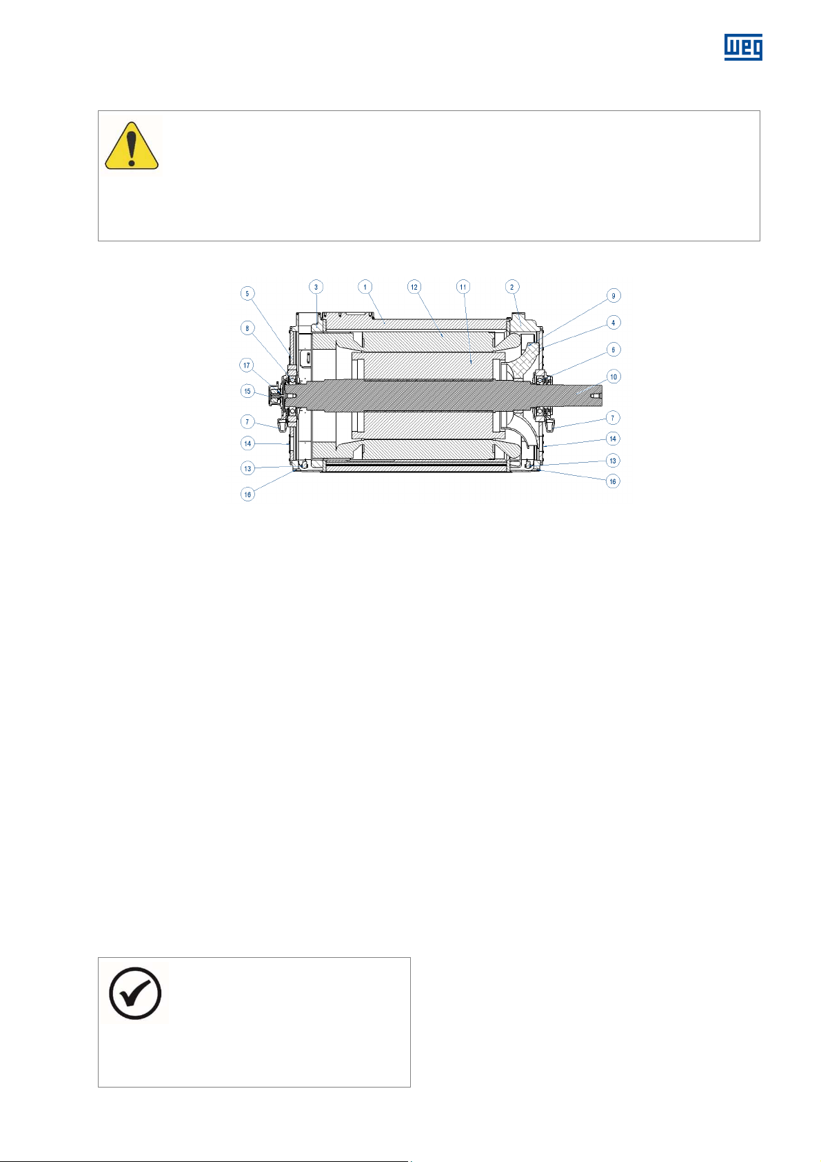
8 MOTOR DISASSEMBLY AND ASSEMBLY
ATTENTION
All the repair, disassembly and assembly services must be performed
The disassembly and assembly sequence
Always use
The bearing temperature sensors are removed
www.weg.net
only by properly qualified and trained
professionals; otherwise, equipment damage and personal injury may occur. If any further explanations are
necessary, consult WEG.
s depend on the motor model.
proper tools and devices. Any damaged part (cracks, dents on machined parts, faulty threads)
must be replaced, avoiding restorations.
8.1 HORIZONTAL MOTORS
NDE DE
Figure 8.1: Horizontal motor parts
DE = Drive end NDE = Non-drive end
Figure 8.1 legend:
1. Frame
2. DE cooling head
3. NDE cooling head
4. DE end shield
5. NDE end shield
6. DE bearing
7. Grease reservoir
8. NDE bearing
9. Fan
10. Shaft
11. Rotor
12. Stator
13. Water leakage sensor
14. Inspection cover
15. Encoder protective cover
16. Drain
17. Retainer
Before disassembling the motor:
1. Disconnect the supply pipes of the cooling water and place the motor in horizontal position;
2. Disconnect the electrical wiring from motor and accessories;
3. Remove grease fittings (if any) and bearing grease reservoirs (7);
4. Remove the shaft grounding brush (if any) and encoder (if any);
5. To prevent damage to the rotor and coil heads, support the shaft on DE and NDE sides.
8.1.1 Disassembly
1. Disconnect the cables of the bearings temperature
sensors in the accessories terminal box;
2. Disassemble the DE bearing (6) and the motor DE end
shield (4) as described in the item 7.10.9.1;
3. Disassemble the NDE bearing (8) and the motor NDE end
shield (5), as described in item 7.10.9.2 ;
4. Using a suitable device, remove the rotor (11) from inside
the stator (12), through the motor DE side, taking care
that the rotor does not drag against the stator core and
coil heads.
NOTES
8.1.2 Assembly
To assembly the motor:
1. Using a suitable device, place the rotor (11) inside the
stator (12), inserting it Through the motor DE side,
taking care that the rotor does not drag against the stator
core or on the coil heads;
2. Assemble the DE bearing (6) and the motor DE end
shield (4), following the procedure in item 7.10.9.5;
3. Assemble the NDE bearing (9) and the motor NDE end
shield (8), following the procedure described in item
7.10.9.5;
4. Install the grease fittings (if any) and the bearing grease
reservoirs (7);
5. Connect the cables of the bearing temperature
sensors on the accessories connection box;
together with the motor end shields. To remove
them, it is necessary to loosen the clamps that
fasten the sensor connection cables to the
motor inside and disconnect them from the
terminals in the terminal box.
6. Install the shaft ground brush (if any);
7. Fill the bearing grease through DE and NDE grease
fittings.
14108242 Installation, operation and maintenance manual – Squirrel cage motor – WGM20 Line l 43
Page 44
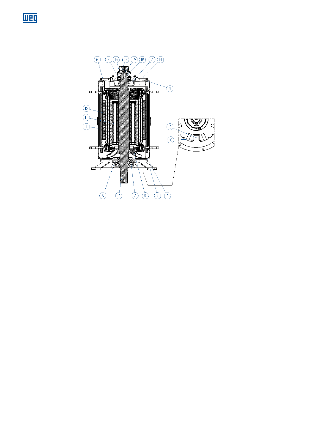
www.weg.net
8.2 VERTICAL MOTORS
NDE
DE
Figure 8.2 legend:
1. Frame
2. DE cooling head
3. NDE cooling head
4. DE end shield
5. NDE end shield
6. DE bearing
Before disassembling the motor:
1. Disconnect the supply pipes from the cooling water and place the motor in horizontal position;
2. Disconnect electrical wiring from motor and accessories;
3. Remove the grease fittings (if any) and bearing grease reservoirs (7);
4. Remove the shaft grounding brush (if any) and encoder (if any);
5. To prevent damage to the rotor and coil heads, support the shaft on DE and NDE sides.
8.2.1 Disassembly
1. Disconnect the cables of the bearings temperature
sensors in the accessories terminal box;
2. Disassemble the DE bearing (6) and the motor DE end
shield (4), as described in item 7.10.9.3;
3. Remove the KMT nut (16) that fasten the NDE bearing;
4. Disassemble the NDE bearing (8) and the motor NDE
end shield (5) as described in item 7.10.9.4;
5. Using a suitable device, remove the rotor (11) from
inside the stator (12), through the motor DE side,
taking care that the rotor does not drag against the
stator core and coil heads.
44 l Installation, operation and maintenance manual – Squirrel cage motor – WGM20 Line 14108242
7. Grease reservoir
8. NDE bearing
9. Fan
10. Shaft
11. Rotor
12. Stator
Figure 8.2: Vertical motor
13. Water leakage sensor
14. Inspection cover
15. Encoder protective cover
16. KMT nut
17. Encoder
18. Drain
19. Retainer
8.2.2 Assembly
To assembly the motor:
1. Using a suitable device, place the rotor (11) into the
stator (12), inserting it through the motor DE side,
taking care that the rotor does not drag against the
stator core and coil heads ;
2. Assemble the DE bearing (6) and the motor DE end
shield (4), following the procedure described in item
7.10.9.5;
3. Assemble the NDE bearing (8), the KMT nut (16) and
the motor NDE end shield (8), following the procedure
described in item 7.10.9.5;
4. Install the grease fittings (if any) and the bearing grease
reservoirs (7);
5. Connect the cables of the bearing temperature
sensors on the accessories connection box;
6. Install the shaft grounding brush (if any);
7. Fill the bearing grease through DE and NDE grease
fittings.
Page 45
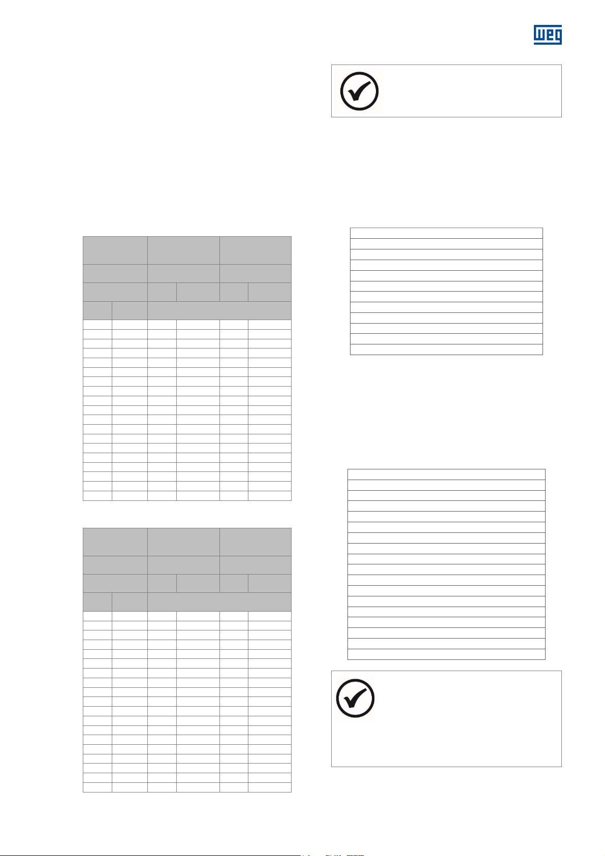
Material /
% Yield
Mol
ycote
Molycote
Pitch
M3 0,5 1,2 0,8 1 0,69
M4 0,7 2,7 1,8 2,4 1,6
M5 0,8 5,4 3,6 4,8 3,2
M6 1 9,3 6,3 8,2 5,5
M8 1,25 22,4 15 20 13
M10 1,5 44 30 39 26
M12 1,75 77 52 67 45
M14 2 123 82 107 72
M16 2 188 126 165 110
M18 2,5 263 176 230 154
M20 2,5 368 246 322 215
M22 2,5 500 332 437 290
M24 3 637 425 557 372
M27 3 926 615 810 538
M30 3,5 1260 838 1102 734
M33 3,5 1704 1130 1490 990
M36 4 2195 1459 1920 1277
M42 4,5 3507 2328 3070 2037
M48 5 5258 3488 4600 3052
Material /
% Yield
Molycote
Molycote
Pitch
M3 0,5 0,6 0,5 0,48 0,32
M4 0,7 1,5 1 1,1 0,76
M5 0,8 3 2 2,2 1,5
M6 1 5,2 3,4 3,8 2,6
M8 1,25 12,3 8,3 9,2 6,2
M10 1,5 24 16 18,2 12,2
M12 1,75 42 28 32 21
M14 2 68 45 51 34
M16 2 104 69 78 52
M18 2,5 145 98 108 72
M20 2,5 202 135 152 101
M22 2,5 274 183 206 137
M24 3 350 233 263 175
M27 3 510 338 382 254
M30 3,5 693 461 520 346
M33 3,5 937 622 703 466
M36 4 1207 802 905 602
M42 4,5 1929 1280 1447 960
M48 5 2892 1918 2170 1440
The resistance class is normally indicated
The spare
8.3 AIR-GAP MEASUREMENT
After disassembling and assembling the motor, it is
necessary to measure the air gap in order to check the
concentricity between rotor and stator.
The difference between the air-gap measured in two
points diametrically opposed must be less than 10% of
the average air gap.
8.4 TIGHTENING TORQUE
Table 8.1 and Table 8.2 shows the tightening torques of
the screws recommended for assembling the motor.
Table 8.1: Screw tightening torque for metal/metal parts
Resistance
class
Strength
Lubricant Dry
Diam
(mm)
Carbon Steel /
8.8 or above
60%
1000
Screws tightening torque (Nm)
Stainless steel /
A2 – 70 or above
70%
Dry
1000
Table 8.2: Screw tightening torque for metal/isolated parts
Resistance
class
Strength
Lubricant Dry
Diam
(mm)
Carbon Steel /
8.8 or above
33%
1000
Screws tightening torque (Nm)
Stainless steel /
A2 – 70 or above
33%
Dry
1000
www.weg.net
NOTE
on
the head of the hex bolts.
8.5 SPARE PARTS
WEG recommends that the spare parts required for the
maintenance procedures recommended in the item 9
Maintenance Plan, be kept in stock, as follows:
8.5.1 Necessary spare parts
DE bearing temperature sensor
NDE bearing temperature sensor
Space heater
Grounding brush
Bearing lubricant
DE bearing
NDE bearing
Cylindrical pressure spring for DE bearing
Cylindrical pressure spring for NDE bearing
Set of seal rings for DE cooling head
Set of seal rings for NDE cooling head
Encoder (if applicable)
The availability of the necessary spare parts is important to
reduce motor downtime due to need replacing
components.
8.5.2 Optional spare parts
The following spare parts are optional and may be
requested to meet any replacement needs.
Vibration sensor for DE bearing (if applicable)
Vibration sensor for NDE bearing (if applicable)
Vibration signal converter for DE bearing (if applicable)
Vibration signal converter for DE bearing (if applicable)
Water temperature sensor (if applicable)
Set of water leakage sensor (if applicable)
Repeater relay for water leak sensor (if applicable)
Water regulating valve (if applicable)
Internal bearing cap for DE bearing
Internal bearing cap for NDE bearing
External bearing cap for DE bearing
External bearing cap for NDE bearing
Grease valve for DE bearing
Grease valve for NDE bearing
Ring with labyrinth for DE bearing
Ring with labyrinth for NDE bearing
Protective ring for DE bearing
Protective ring for NDE bearing
Table 8.3: Necessary spare parts
Table 8.4: Optional spare parts
14108242 Installation, operation and maintenance manual – Squirrel cage motor – WGM20 Line l 45
NOTES
When ordering spare parts, inform the motor
model and serial number, according to the
motor nameplate.
parts must be stored in clean, dry,
well-ventilated environments and, if possible,
at constant temperature.
Page 46
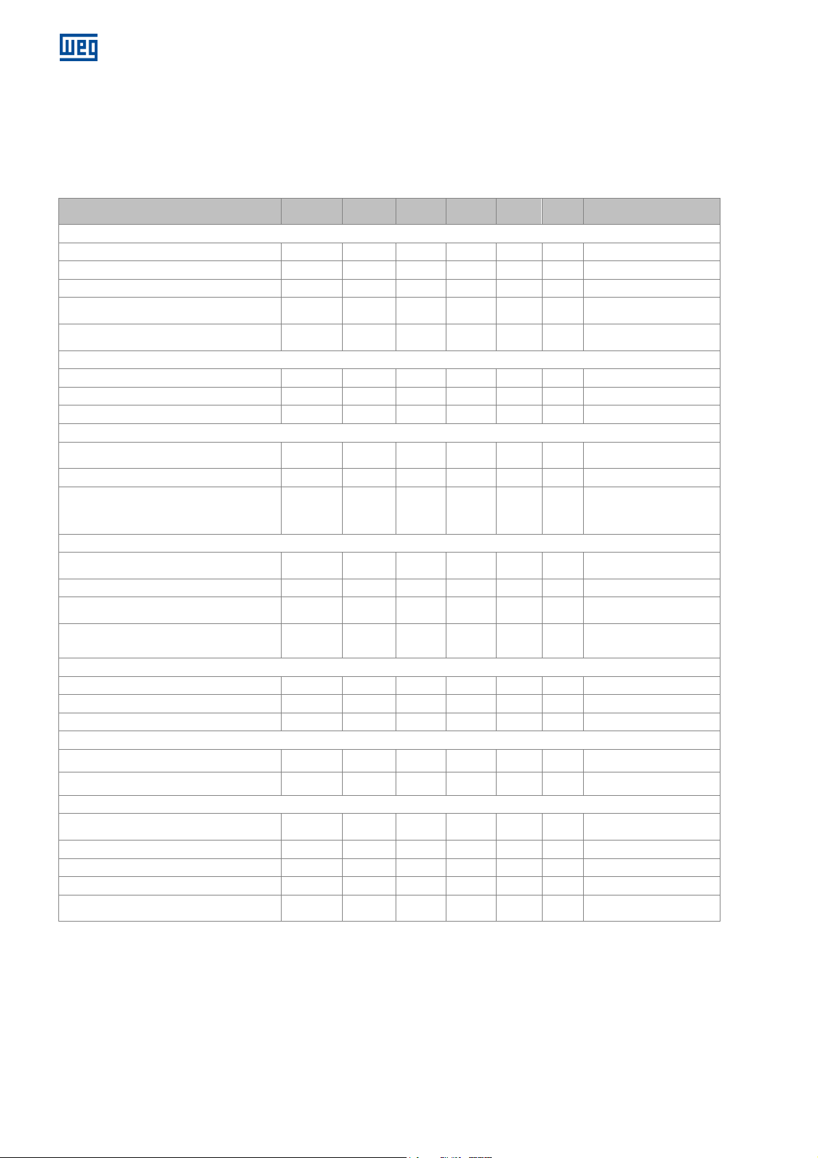
www.weg.net
3
6
3
Verification of
the
fastening of
stator
Measurement of the winding insulation
Control of n
oise, vibration, leak
s and
According to the period
Verification
of
the temperature, flow and
Check the water inlet and
outlet connections
Check for tightness, leaks.
If there is evidence of change
Check after the first week of
Check after the
first week of
Inspection of
the
cleanliness
, noise,
vibration
Retightening of
electrical and grounding
9 MAINTENANCE PLAN
The maintenance plan described in Table 9.1 is only referential, and the intervals between each maintenance intervention
may vary according to the motor location and operating conditions.
For the associated equipment, such as the water supply unit or control and protection system, it is necessary to refer to their
specific manuals.
MOTOR PART Weekly Monthly
Visual inspection of the stator.
Cleaning of the stator.
Inspection of the slot wedges.
terminals.
resistance.
Visual inspection.
Cleaning of the rotor.
Inspection of the shaft (wear, incrustations).
temperature.
Lubricant quality control.
Table 9.1: Maintenance plan
months
months
Annual
STATOR
x
x
x
ROTOR
x
BEARINGS
x
x
years
x
x
x
x
Lubricant change.
COOLING SYSTEM
pressure of the cooling water.
Inspection of the cooling water quality.
with the cooling circuit.
Cleaning of the frame internal channels and
cooling heads.
x
x
x
PROTECTION AND CONTROL EQUIPMENT
Recording of the values.
Inspection of the operation.
Disassembly and operation test.
x
x
COUPLING
Inspection of the alignment.
Inspection of the coupling fastening.
WHOLE MOTOR
and temperature.
Drainage of condensed water.
Retightening of the screws.
Cleaning of the terminal boxes.
connections.
x
x
x
x
x
x
x
x
indicated on the bearing
nameplate.
in the water flow or loss of
load.
operation.
operation.
46 l Installation, operation and maintenance manual – Squirrel cage motor – WGM20 Line 14108242
Page 47
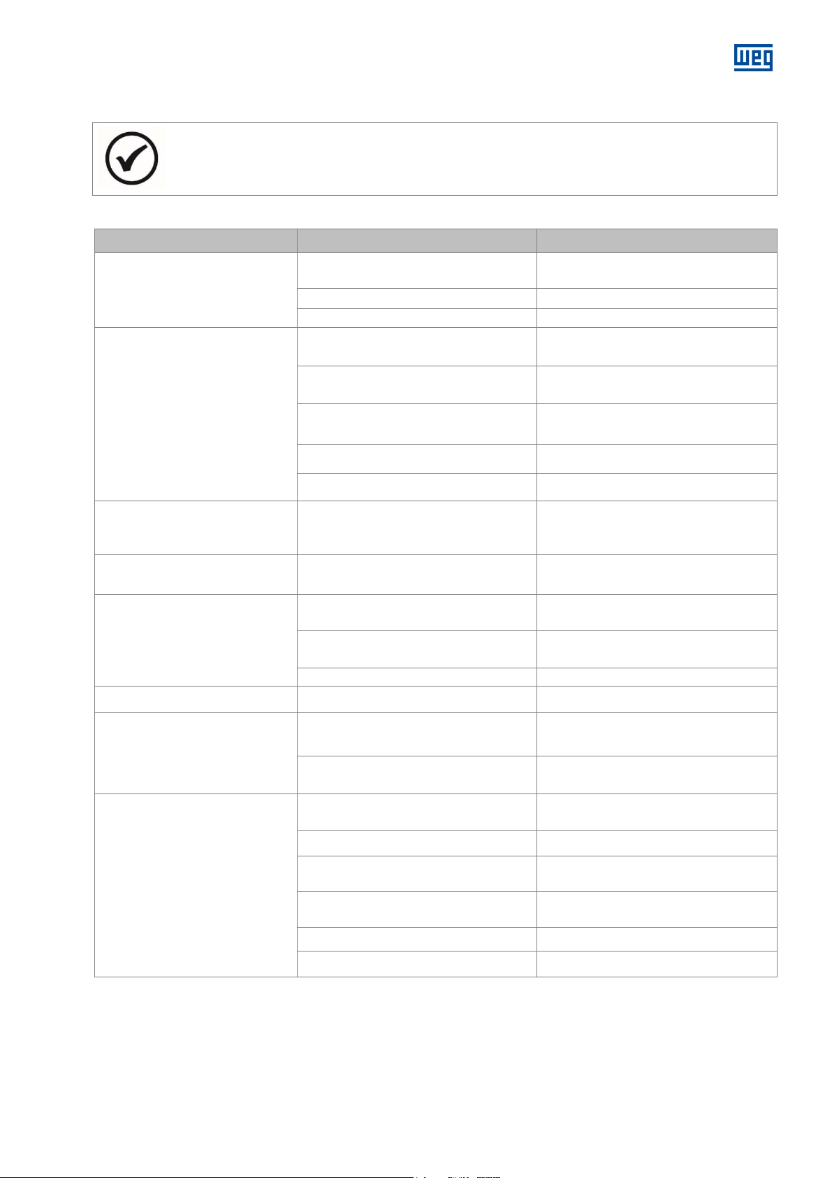
10 ABNORMALITIES, CAUSES AND SOLUTIONS
The
Check the sizing of the installation
A power cable was interrupted after the
The stator current oscillates under
www.weg.net
NOTE
Table 10.1 present a basic list of abnormalities, causes and corrective actions. In case of questions, consult
WEG.
ABNORMALITY POSSIBLE CAUSES CORRECTION
Neither coupled nor uncoupled
does the motor start
Motor starts with no load, but fails
when load is applied. It starts very
slowly and does not reach the
rated speed
load with double the slip
frequency. The motor presents a
humming noise during starting
Very high no load current Power supply voltage is too high
Table 10.1: Basic list of abnormalities, causes and corrective actions
At least two power cables are interrupted,
without voltage
Rotor is locked Unlock the rotor
Damaged bearing Replace the bearing
Load torque is too high during the start.
Power supply voltage is too low
Very high voltage drop in the power cables
Rotor with faulty or interrupted bars Check and repair the rotor winding
start
Rotor winding is interrupted Check and repair the rotor winding
Check the control panel, the power cables
and the terminals
Do not apply load to the driven machine
during the start
Measure the power supply voltage and set
it to the correct value.
(transformer, cable section, relays, circuit
breakers, etc.)
Check the power cables
Measure the power supply voltage and set
it to the correct value
Hot spots in the stator winding.
Hot spots in the rotor.
Abnormal noise during operation
with load.
When coupled, there is noise;
when uncoupled, the noise
disappears
Short-circuit between turns Rewind the stator
Interruption of parallel wires or phases of
the stator winding
Faulty connection Redo the connection
Interruptions in the rotor bars Repair the rotor or replace it
Mechanical causes
Electrical causes
Defect in the coupling parts or in the driven
machine
Defect in the gear coupling Align the driving set
Unaligned/unleveled base
Faulty balancing of the components or of
the driven machine
Defective coupling Repair the coupling
Wrong rotation direction of the motor Invert the connection of two phases
Redo the connection of the stator cables
The noise normally decreases when the
speed reduces; see also:
when uncoupled”
The noise disappears when the motor is
switched off. Contact the manufacturer
Check the power transmission, the
coupling and the alignment
Align/level the motor and the driven
machine
Perform new balancing
“noisy operation
14108242 Installation, operation and maintenance manual – Squirrel cage motor – WGM20 Line l 47
Page 48

www.weg.net
Do
not exceed 110% of the rated voltage,
ABNORMALITY POSSIBLE CAUSES CORRECTION
Stator winding becomes very
hot under load
Insufficient cooling due to dirty water
channels
Overload
High number of starts or moment of inertia
too high
Voltage too high, therefore, the iron losses
increase
Voltage too low, therefore, the current is
very high
Interruption in a power cable or in a winding
phase
Rotor drags against the stator
The operating condition does not
correspond to the nameplate data
Unbalance in the power supply (blown fuse,
wrong command)
Dirty windings Clean the windings
Rotation direction is not compatible with the
used fan
Clean the water passage channels
Measure the stator current. Reduce the
load. Analyze the motor application
Reduce the number of starts
except when otherwise specified on the
nameplate
Check the supply voltage and the voltage
drop on the motor
Measure the current in all the phases and, if
necessary, correct it
Check the air-gap, operating conditions
(vibration etc.), bearing conditions
Keep the operating condition according to
the nameplate or reduce the load
Check if there is voltage unbalance or
operation with two phases and correct it
Check the fan regarding to the motor
rotation direction
Unbalance Perform new balancing
Noisy operation when
uncoupled
Interruption in one phase of the stator
winding
Fastening screws are loose Retighten and lock the screws
The rotor balancing conditions become
worse after the assembly of the coupling
Resonance in the foundation Adjust the foundation
Motor frame deformed Check flatness of the base
Bent shaft Check the rotor balancing and eccentricity
Air-gap is not even Check shaft warping or rolling bearing wear
Measure the current of all connecting cables
Balance the coupling
11 ENVIRONMENTAL INFORMATION
11.1 PACKAGE
Electric motors are supplied in cardboard, polymer, wood
or metallic material packages. These materials are
recyclable or reusable and must be properly disposed
according to the current regulations of each country. All
the wood used in the packaging of WEG motors comes
from reforestation and receives anti-fungal treatment.
11.2 PRODUCT
Electric motors, under the constructive aspect, are
manufactured mainly with ferrous metals (steel, cast iron),
nonferrous metals (copper, aluminum) and plastic.
The electric motor, in general, is a product that has a long
useful life; however, when it must be disposed, WEG
recommends that the materials of the packaging and of
the product be properly separated and sent for recycling.
48 l Installation, operation and maintenance manual – Squirrel cage motor – WGM20 Line 14108242
The non-recyclable materials must be properly disposed
according to the environmental regulations, i.e., in
industrial landfills, co-processed in cement kilns or
incinerated. The service providers for recycling, disposal in
industrial landfills, co-processing or incineration of waste
must be properly licensed by the environmental agency of
each state to carry out these activities.
11.3 HAZARDOUS WASTE
Grease and oil waste used to lubricate the bearings
should be disposed, according to the instructions of the
relevant environmental agencies, because its improper
disposal can cause impacts to the environment.
Page 49
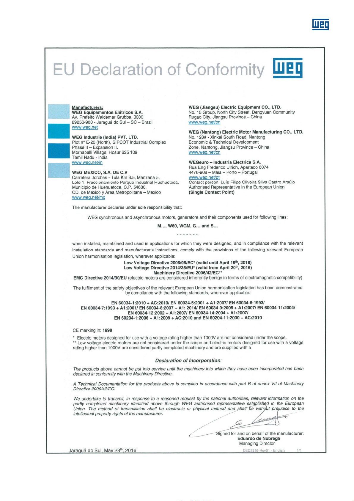
12 DECLARATION OF CONFORMITY
www.weg.net
14108242 Installation, operation and maintenance manual – Squirrel cage motor – WGM20 Line l 49
Page 50

www.weg.net
13 SERVICE NETWORK
To consult the Service Network, access the website www.weg.net.
14 WARRANTY TERM
These products, when operated under the conditions stipulated by WEG in the operating manual for such product,
are warranted against defects in workmanship and materials for twelve (12) months from start-up date or eighteen
(18) months from manufacturer shipment date, whichever occurs first.
However, this warranty does not apply to any product which has been subject to misuse, misapplication, neglect
(including without limitation, inadequate maintenance, accident, improper installation, modification, adjustment,
repair or any other cases originated from inadequate applications).
The company will neither be responsible for any expenses incurred in installation, removal from service,
consequential expenses such as financial losses nor transportation costs as well as tickets and accommodation
expenses of a technician when this is requested by the customer.
The repair and/or replacement of parts or components, when effected by WEG within the Warranty period do not
give Warranty extension, unless otherwise expressed in writing by WEG.
This constitutes WEG's only warranty in connection with this sale and is in lieu of all other warranties, expressed
or implied, written or oral.
There are no implied warranties of merchantability or fitness for a particular purpose that apply to this sale.
No employee, agent, dealer, repair shop or other person is authorized to give any warranties on behalf of WEG
nor to assume for WEG any other liability in connection with any of its products.
In case this happens without WEG's authorization, Warranty is automatically cancelled.
LIABILITY
xcept as specified in the foregoing paragraph entitled "Warranty Terms for Engineering Products", the
E
company shall have no obligation or liability whatsoever to the purchaser, including, without limitation, any claims
for consequential damages or labor costs, by reason of any breach of the express warranty described therein.
The purchaser further hereby agrees to indemnify and hold the company harmless from any causes of action
(other than cost of replacing or repairing the defective product as specified in the foregoing paragraph entitled
"Warranty Terms for Engineering Products"), arising directly or indirectly from the acts, omissions or
negligence of the purchaser in connection with or arising out of the testing, use, operation, replacement or
repair of any product described in this quotation and sold or furnished by the company to the purchaser.
WEG Group - Energy Business Unit
Jaraguá do Sul - SC - Brazil
Phone: 55 (47) 3276-4000
www.weg.net
50 l Installation, operation and maintenance manual – Squirrel cage motor – WGM20 Line 14108242
Page 51

ARGENTINA
WEG EQUIPAMIENTOS ELECTRICOS S.A.
Sgo. Pampiglione 4849
Parque Industrial San Francisco
2400 - San Francisco
Phone: +54 (3564) 421484
www.weg.net/ar
AUSTRALIA
WEG AUSTRALIA PTY. LTD.
14 Lakeview Drive, Scoresby 3179,
Victoria
Phone: +03 9765 4600
www.weg.net/au
AUSTRIA
WATT DRIVE ANTRIEBSTECHNIK GMBH *
Wöllersdorfer Straße 68
2753, Markt Piesting
Phone: + 43 2633 4040
www.wattdrive.com
LENZE ANTRIEBSTECHNIK GES.M.B.H *
Ipf - Landesstrasse 1
A-4481 Asten
Phone: +43 (0) 7224 / 210-0
www.lenze.at
BELGIUM
WEG BENELUX S.A.*
Rue de l’Industrie 30 D,
1400 Nivelles
Phone: +32 67 888420
www.weg.net/be
BRAZIL
WEG EQUIPAMENTOS ELÉTRICOS S.A.
Av. Pref. Waldemar Grubba, 3000,
CEP 89256-900 Jaraguá do Sul – SC
Phone: +55 47 3276-4000
www.weg.net/br
CHILE
WEG CHILE S.A.
Los Canteros 8600,
La Reina - Santiago
Phone: +56 2 2784 8900
www.weg.net/cl
CHINA
WEG (NANTONG) ELECTRIC MOTOR
MANUFACTURING CO. LTD.
No. 128# - Xinkai South Road, Nantong
Economic & Technical Development Zone,
Nantong, Jiangsu Province
Phone: +86 513 8598 9333
www.weg.net/cn
COLOMBIA
WEG COLOMBIA LTDA
Calle 46A N82 – 54
Portería II - Bodega 6 y 7
San Cayetano II - Bogotá
Phone: +57 1 416 0166
www.weg.net/co
DENMARK
WEG SCANDINAVIA DENMARK *
Sales Office of WEG Scandinavia AB
Verkstadgatan 9 - 434 22 Kumgsbacka,
Sweden
Phone: +46 300 73400
www.weg.net/se
FRANCE
WEG FRANCE SAS *
ZI de Chenes - Le Loup13 / 38297 Saint
Quentin Fallavier,
Rue du Mo¬rellon - BP 738/
Rhône Alpes, 38 > Isère
Phone: + 33 47499 1135
www.weg.net/fr
GREECE
MANGRINOX*
14, Grevenon ST.
GR 11855 - Athens, Greece
Phone: + 30 210 3423201-3
www.weg.net/gr
GERMANY
WEG GERMANY GmbH*
Industriegebiet Türnich 3 Geigerstraße 7
50169 Kerpen-Türnich
Phone: + 49 2237 92910
www.weg.net/de
GHANA
ZEST ELECTRIC MOTORS (PTY) LTD.
15, Third Close Street Airport Residential Area,
Accra
Phone: +233 3027 66490
www.zestghana.com.gh
HUNGARY
AGISYS AGITATORS & TRANSMISSIONS
LTD.*
Tó str. 2. Torokbalint, H-2045 Phone: + 36
(23) 501 150
www.agisys.hu
INDIA
WEG ELECTRIC (INDIA) PVT. LTD.
#38, Ground Floor, 1st Main Road,
Lower Palace, Orchards,
Bangalore, 560 003
Phone: +91 804128 2007
www.weg.net/in
ITALY
WEG ITALIA S.R.L.*
Via Viganò de Vizzi, 93/95
20092 Cinisello Balsamo, Milano Phone: + 39
2 6129 3535
www.weg.net/it
FERRARI S.R.L.*
Via Cremona 25 26015
Soresina (CR), Cremona
Phone: + 39 (374) 340-404
www.ferrarisrl.it
STIAVELLI IRIO S.P.A.*
Via Pantano - Blocco 16 - Capalle 50010 ,
Campi Bisenzio (FI)
Phone: + 39 (55) 898.448
www.stiavelli.com
JAPAN
WEG ELECTRIC MOTORS JAPAN CO., LTD.
Yokohama Sky Building 20F, 2-19-12
Takashima, Nishi-ku, Yokohama City,
Kanagawa, Japan 220-0011
Phone: + 81 45 5503030
www.weg.net/jp
MEXICO
WEG MEXICO, S.A. DE C.V.
Carretera Jorobas-Tula
Km. 3.5, Manzana 5, Lote 1 Fraccionamiento
Parque Industrial
Huehuetoca
Estado de México - C.P. 54680
Phone: +52 55 53214275
www.weg.net/mx
NETHERLANDS
WEG NETHERLANDS *
Sales Office of WEG Benelux S.A. Hanzepoort
23C, 7575 DB Oldenzaal
Phone: +31 541 571090
www.weg.net/nl
PORTUGAL
WEG EURO - INDÚSTRIA ELÉCTRICA, S.A.*
Rua Eng. Frederico Ulrich,
Sector V, 4470-605 Maia,
Apartado 6074, 4471-908 Maia, Porto
Phone: +351 229 477 705
www.weg.net/pt
RUSSIA
WEG ELECTRIC CIS LTD *
Russia, 194292, St. Petersburg, Pro¬spekt
Kultury 44, Office 419
Phone: +7 812 3632172
www.weg.net/ru
SOUTH AFRICA
ZEST ELECTRIC MOTORS (PTY) LTD.
47 Galaxy Avenue, Linbro Business
Park Gauteng Private Bag X10011
Sandton, 2146, Johannesburg
Phone: +27 11 7236000
www.zest.co.za
SPAIN
WEG IBERIA INDUSTRIAL S.L
C/ Tierra de Barros, 5-7
28823 Coslada, Madrid
Phone: +34 91 6553008
www.weg.net/es
SINGAPORE
WEG SINGAPORE PTE LTD
159, Kampong Ampat, #06-02A KA PLACE.
368328
Phone: +65 68581081
www.weg.net/sg
SWEDEN
WEG SCANDINAVIA AB *
Box 27, 435 21 Mölnlycke
Visit: Designvägen 5, 435 33
Mölnlycke, Göteborg
Phone: +46 31 888000
www.weg.net/se
SWITZERLAND
BIBUS AG
Allmendstrasse 26, 8320 – Fehraltorf
Phone: + 41 44 877 58 11
www.bibus-holding.ch
UNITED ARAB EMIRATES
The Galleries, Block No. 3, 8th Floor,
Office No. 801 - Downtown Jebel Ali
262508, Dubai
Phone: +971 (4) 8130800
www.weg.net/ae
UNITED KINGDOM
WEG ELECTRIC MOTORS (U.K.) LTD.*
Broad Ground Road - Lakeside Redditch,
Worcestershire B98 8YP
Phone: + 44 1527 513800
www.weg.net/uk
ERIKS *
Amber Way, B62 8WG Halesowen
West Midlands
Phone: + 44 (0)121 508 6000
BRAMMER GROUP *
PLC43-45 Broad St, Teddington
TW11 8QZ
Phone: + 44 20 8614 1040
USA
WEG ELECTRIC CORP.
6655 Sugarloaf Parkway, Duluth, GA 30097
Phone: +1 678 2492000
www.weg.net/us
VENEZUELA
WEG INDUSTRIAS VENEZUELA C.A.
Centro corporativo La Viña Plaza,
Cruce de la Avenida Carabobo con la calle
Uzlar de la Urbanización La Viña / Jurisdicción
de la Parroquia San José - Valencia
Oficinas 06-16 y 6-17, de la planta tipo 2, Nivel
5, Carabobo
Phone: (58) 241 8210582
www.weg.net/ve
*
* European Union Importers
.*
 Loading...