

Page 1
Motors | Automation | Energy | Transmission & Distribution | Coatings
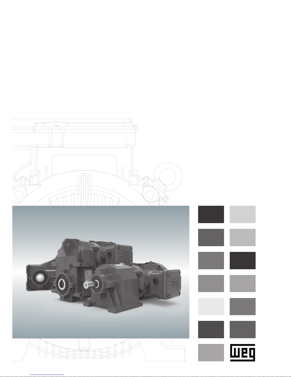
WG20 Geared Motors - Mounting Instruction
Page 2
E-2 | WG20 Geared Motors
1. General E-3
1.1. Safety and information markings E-3
1.2. General information E-3
1.3. Exclusion of liability E-3
1.4. Indication of copyright and protective right E-3
2. General safety E-4
3. Gear unit / Geared motor description E-5
3.1. Nameplate E-5
3.2. Type designation E-5
4. Transport E-7
5. Storage E-8
6. Gear unit construction E-9
6.1. Basic design principles helical gear unit C E-10
6.2. Basic design principles parallel shaft gear unit F E-12
6.3. Basic design principles helical bevel gear unit K E-14
7. Mechanical installation E-16
7.1. Preparatory work gear unit E-16
7.2. Preparatory work motor E-16
7.3. Setting up the gear unit / geared motor E-18
8. Check list - Gear unit E-24
9. Check list - Motor E-24
10. Startup E-24
10.1. Electrical connection of the motor E-24
10.2. Direction of rotation E-25
10.3. Oil level in the gear unit as delivered E-25
11. Operation E-25
12. Malfunction E-26
13. Inspection and maintenance E-27
13.1. Inspection and maintenance intervals E-27
13.2. Inspection and maintenance work on gear unit E-27
14. Lubricants E-28
15. Mounting positions and lubricant capacity E-29
15.1. Helical gear units C E-29
15.2. Parallel shaft gear units F E-30
15.3. Helical bevel gear units K E-31
16. Position of terminal box and cable entry E-32
17. Terminal board connection E-32
18. Optional motor devices E-34
18.1. Anti-condensation heating E-34
18.2. Drain E-34
18.3. Forced cooling E-34
18.4. Temperature controller Bimetal switch „NC contact“ (TH) E-35
18.5. PTC Thermistor protection (TF) E-35
18.6. Brake E-35
19. Table of Tightening Torques E-38
20. Disposal E-38
21. Declaration of incorporation E-39
22. EU declaration of conformity ATEX 2014/34/EU E-40
23. EU declaration of conformity: low voltage directive 2014/35/EU E-41
Page 3
WG20 Geared Motors | E-3
1. General
1.1. Safety and information markings
1.2. General information
1.3. Exclusion of liability
1.4. Indication of copyright and protective right
This Mounting Instruction (MI) is part of the gear unit as supplied and must be read carefully before working with the gear
unit. The instructions in the MI must be followed. Keep the MI close to the gear unit.
We assume no liability for damages or disruptions of operations resulting from the failure to observe this MI.
In order to develop the product further, the producer reserves the right to make modications to the individual components
or assemblies that are believed to be useful to improve the product, while maintaining its essential characteristics.
Protection class:
The gears are in accordance with Protection Class IP 65.
Motors are designed within Protection Class IP 55 at minimum (see nameplate).
Intended use:
The gears / geared motors are exclusively assigned for the generation of a dened rotary motion within machinery and
plants. The gears comply with the basic requirements of the machinery directive 2006/42/EC as far as possible.
Any other use or utilisation above this is deemed a not intended use. The user / operator of the machine / plant is solely
liable for damages resulting therefrom.
The details in this mounting instruction, on the nameplate as well as in other technical documentation, are to be considered
and observed.
Intended use for motors:
The motors comply with the basic requirements of the Low Voltage Directive 2014/35/EU. They are designed for power
operating as well as operating in combination with frequency inverters.
Standard motors are designed for use at:
■ Ambient temperatures of -20°C (-4°F) to +40°C (104°F)
■ Altitudes of ≤ 1,000 m above sea level
You must comply with the information contained in this MI to ensure safe operation of the gear unit, geared motor and to
achieve the specied product characteristics and performance requirements.
The producer assumes no liability for injury to people or damage to equipment or property resulting from non-observance
of this MI. In such cases, any liability for defects is excluded.
All technical documents are protected in the sense of the copyright law. The processing, reproduction and dissemination of
it, even in extracts, as well as other utilisation is not allowed, unless it has been expressly conceded in written form.
WARNING!
All safety and warning instructions must be followed without exception!
Warning of electrical or mechanical danger
ATTENTION!
Important instructions for safe and trouble-free operation
Page 4
E-4 | WG20 Geared Motors
2. General safety
The customer is responsible for setting up the drive in accordance with good engineering practices.
The instructions in this Mounting Instruction must be followed to achieve the conrmed characteristics of the drive units and
to ensure approval in case of warranty claims.
Make certain that you never put damaged products into operation!
Read this Mounting Instruction carefully before you begin any setup, installation or maintenance work.
Installation, start-up, maintenance and repair work on the gear unit / gear motor as well as on electrical accessory equip-
ment may only be performed by qualied technical personnel, taking the following items into account:
■ Operating Instructions
■ Information labels/tags on the gear unit / geared motor
■ All other project documents, setup manuals, operating manuals
■ Drive-specic specications and requirements belonging to the drive unit
■ The applicable regional and national regulations on safety and accident prevention
Work is only permitted:
■ on the stationary drive,
■ while disconnected and
■ prevented from being switched on again.
Operation of the drive unit by means of a frequency inverter may only occur if the specications shown on the motor nameplate have been carried out.
WARNING!
Page 5
WG20 Geared Motors | E-5
3. Gear unit / Geared motor description
3.1. Nameplate
3.2. Type designation
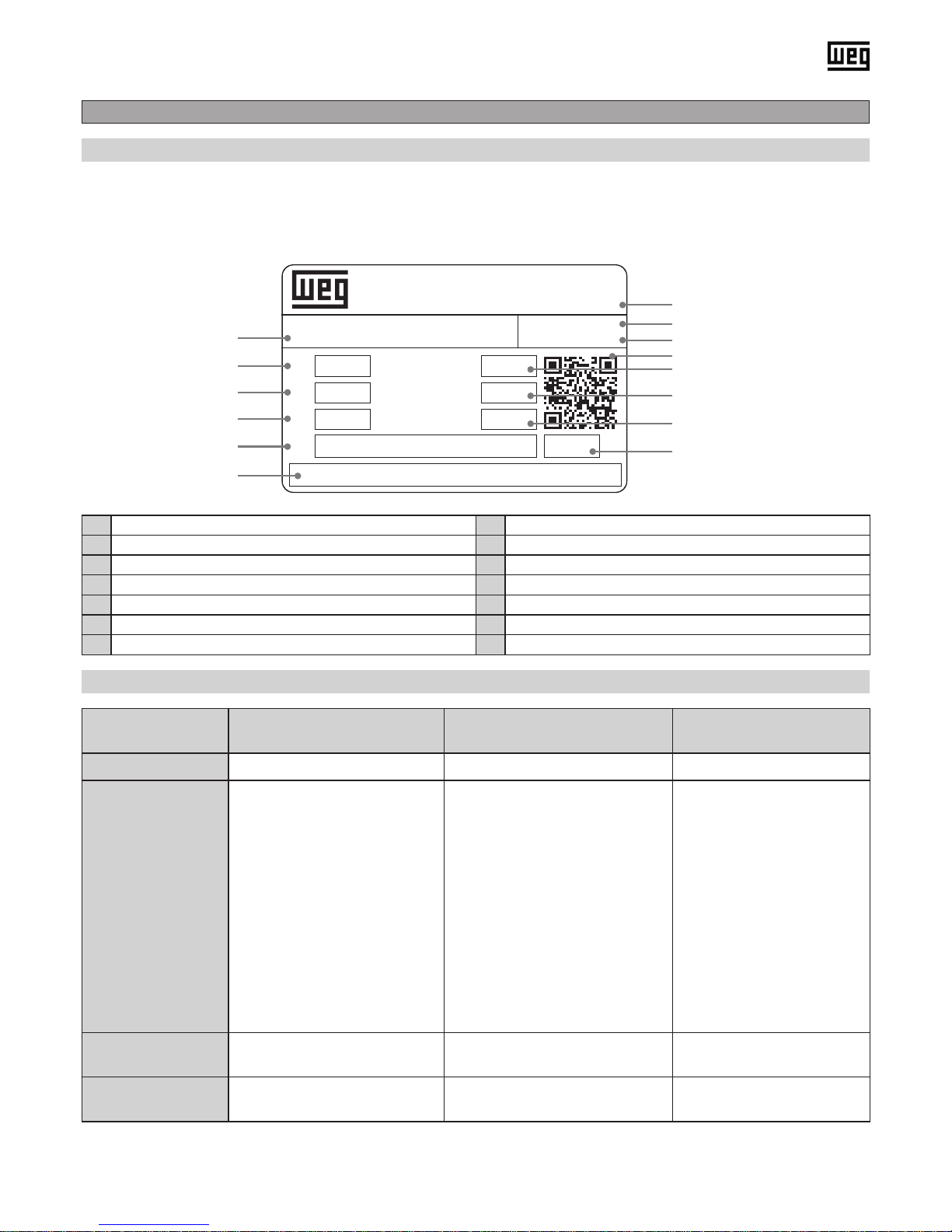
All data on the nameplate of the gear denes the limits of its intended usage. It is imperative to adhere to this data.
Please take further technical data and drawings from the latest geared motor catalogue.
a Type code h Serial number
b Motor power i Material number
c Output torque j QR code with link to additional data
d Service factor k Output speed
e Oil quantity and type l Total gear ratio
f Space for additional information m Mounting position
g Production date n Weight
Type designation
(example)
CG02-11N-63-04F-TH-TF-BR2 FH032-11P-80-04F-TH-TF-BR10 KH022-11N-63-04F-TH-TF
Type C (Helical gear unit) F (Parallel shaft gear unit) K (Helical bevel gear unit)
Possible gear unit
execution
CA … … Foot and ange type
with output shaft
CF … B14-ange housing with
output shaft
CG … Flange type with output
shaft
CW … Foot and B14-ange
type with output shaft
FD … Hollow shaft and shrink
disc
FF … B5-ange type with output
shaft
FH … Hollow shaft
FO … B5-ange type with hollow
shaft
FP … B5-ange type with hollow
shaft and shrink disc
FS … Output shaft
FT … Hollow shaft with rubber
buffer
FU … Hollow shaft with shrink
disc and rubber buffer
KD … Hollow shaft and
shrink disc
KF … B5-ange type with
output shaft
KH … Hollow shaft
KO … B5-ange type with
hollow shaft
KP … B5-ange type with
hollow shaft and shrink disc
KS … Output shaft
KT … Hollow shaft with
torque arm
KU … Hollow shaft with
shrink disc and torque arm
Possible gear unit
sizes
00, 01, 03, 05, 06, 07, 08 02, 03, 04, 05, 06, 07 02, 03, 04, 05, 06, 07
Possible gear
stages
00, 01: 2 stages
03-08: 2 or 3 stages
02, 03: 2 stages
04-07: 2 or 3 stages
02: 2 stages
03-07: 3 stages
Watt Drive Antriebstechnik
2753 Markt Piesting, Austria
www.wattdrive.com
MADE IN
AUSTRIA
SN:
Mat.:
P1 kW rpm
Oil kg
M2 Nm i
fB
CG012-11H-80-04F-TH-TF
12SEP16
16I18056
0.75
0.1 l - ISO VG 220 CLP
16.6
116
62 14.88
1.4 M1
WG20
a
b
c
d
e
f
g
h
i
j
k
l
m
n
WG20 nameplate (example)
Page 6
E-6 | WG20 Geared Motors
Gear unit input types
63... - 180... Motor frame size
I.. IEC adapter
N.. NEMA adapter
Optional additional motor devices
Type designation (example) 11P 100L-04F SH K1 KB MIP BRH40 FL SD
11P 100L-04F Motor type
TH, TF, KTY Temperature control
FL Forced cooling
IG, SG Encoder
BR.. Brake
BBR.. Double brake
BRH.. Brake with manual release
BRHA.. Brake with manual release and locking device
KKM, RSM Back stop
U, UW Unventilated
KB Drain
SH Anti condensation heating
K1, K2 Climatic protection
MIP, MIG Terminal box design
SD Protection cap
HR Hand wheel
ZM Metal fan
ZL Fly wheel fan
ZWM, ZWV Second shaft end
Page 7
WG20 Geared Motors | E-7
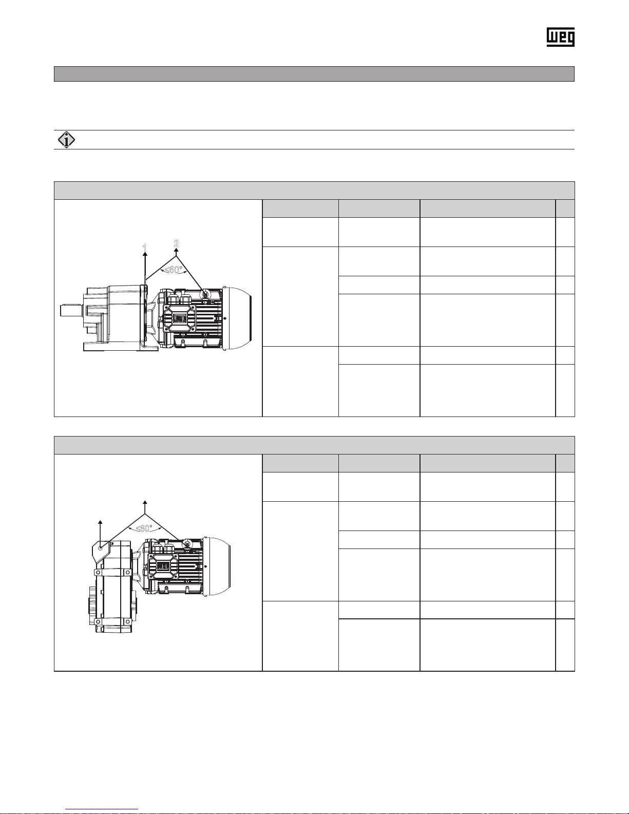
4. Transport
After delivery, the unit must be inspected for any damage that may have occurred during transport. In case of damage do
not put the motor into operation.
Helical geared motors C
1
<
60°
1
2
Gear size Motor size Load handling
C00
C01
all
No equipment for
load handling provided
-
C03
C05
C06
63 - 71
No equipment for
load handling provided
-
80 - 90 Lifting eye on the gearbox 1
100 - 132
Lifting eye on the gearbox
+ eye bolt on motor
(max. angle of 60° between
the ropes)
2
C07
C08
63 - 90 Lifting eye on the gearbox 1
100 - 180
Lifting eye on the gearbox
+ eye bolt on motor
(max. angle of 60° between
the ropes)
2
Parallel shaft geared motors F
1
<
60°
2
Gear size Motor size Load handling
F02 all
No equipment for
load handling provided
-
F03
F04
F05
63 - 71
No equipment for
load handling provided
-
80 - 90 Support hole 1
100 - 132
Support hole + eye bolt on
motor (max. angle of 60°
between the ropes)
2
F06
F07
63 - 90 Support hole 1
100 - 160
Support hole + eye bolt on
motor (max. angle of 60°
between the ropes)
2
ATTENTION!
To lift the geared motors, you have to use the following load handling equipment:
Page 8
E-8 | WG20 Geared Motors
5. Storage
General:
The following items must be taken into account when storing the gear units:
■ In general, the drive units must be stored in closed rooms.
■ Ambient temperature max. 25 °C (77 °F)
■ Relative humidity max. 80 %
■ The drive units are to be protected from exposure to the sun or UV light.
■ No aggressive or corrosive materials are to be stored in the vicinity of the unit.
■ The gear units are to be stored in the same position that is intended for a later use.
■ The gear units are to be rotated 1-2 revolutions on the output side every 6 months to ensure that the interior parts are
wetted with lubricant.
■ The units are to be protected from mechanical loads and exposure to outside forces.
Long-term storage:
■ When the gear units are to be stored for longer than 12 months, they must be completely lled with lubricant as stated
on the nameplate or lubricant plate.
■ Unnished, bare-metal parts on the outside of the unit are to be protected with a corrosion protection product
(inspection every 6 months is recommended). The corrosion protection must be replaced after one year.
■ Before starting the gear unit, drain the lubricant from it. If more than one lubricant chamber is present, make certain that
all of the lubricant chambers have been drained out.
■ Gaskets settle, especially after a longer period without loading. Before starting, the screws must be retightened.
■ Then ll the gear unit with the lubricant type specied on the nameplate using the specied quantity.
■ If the gear units are stored for longer than 24 months before being put into service, they must be checked for leaks.
If there are any visible cracks on the surfaces of sealing elements, such parts must be replaced.
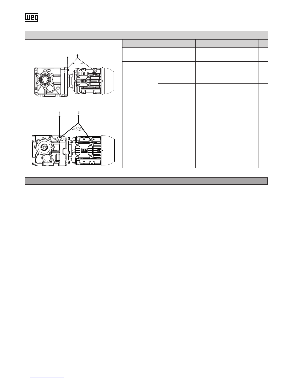
Helical bevel geared motors K
<
60°
1
2
Gear size Motor size Load handling
K02 all
No equipment for load
handling provided
-
K03
K04
K05
63 - 71
No equipment for load
handling provided
-
80 - 90 Lifting eye on the gearbox 1
100 - 132
Lifting eye on the gearbox
+ eye bolt on motor
(max. angle of 60° between
the ropes)
2
<
60°
1
2
K06
K07
63 - 90 Lifting eye on the gearbox 1
100 - 160
Lifting eye on the gearbox
+ eye bolt on motor
(max. angle of 60° between
the ropes)
2
Page 9

WG20 Geared Motors | E-9
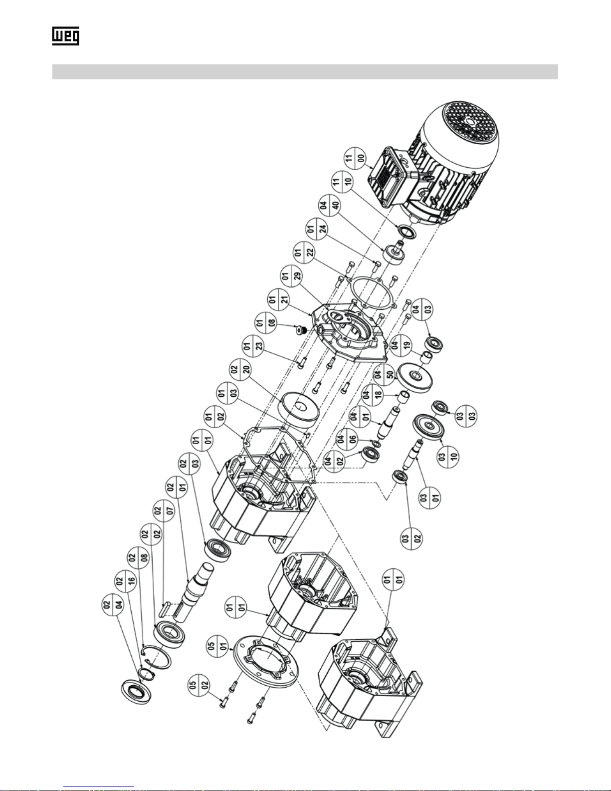
6. Gear unit construction
The following drawings basically show the construction of the various dry series in theory. Deviations from other gear unit
sizes and design versions are possible per gear unit series.
Legend for the construction drawings:
Position Description Position Description
01
01
01
01
01
01
01
01
01
01
01
01
01
01
01
01
01
01
02
02
02
02
02
02
02
02
02
02
02
02
02
02
02
02
02
02
02
03
03
03
03
03
03
03
03
03
03
00
01
02
03
04
05
06
08
09
20
21
22
23
24
25
26
27
29
00
01
02
03
04
05
06
07
08
09
10
11
12
13
14
15
16
17
20
00
01
02
03
04
05
06
07
10
20
Kit Housing
Housing
Gasket
Pin
Gasket
Inspection cover
Inspection cover screws
Plug
Vent plug
Kit Case cover/Motor adapter
Case cover/Motor adapter
Motor gasket
Screws
Screws
Screws
Pin screws
Hexagon nut
Lifting eye/Eye bolt
Kit Output shaft
Output shaft
Bearing 1 (C), 1/2 (F, K)
Bearing 2
Shaft sealing 1 (C), 1/2 (F, K)
Shaft sealing 2
Key
Key
Circlip
Distance sleeve
Bearing cover
Adjusting washer
Shrink disc
Glycodur bush
Shim washer
Shim washer
Circlip 2
Shim washer
Output gear
Kit Intermediate pinion shaft
Intermediate pinion shaft
Bearing 5
Bearing 6
Circlip 1
Circlip 2
Bearing cover
Key
1st stage gear
Bevel pair
04
04
04
04
04
04
04
04
04
04
04
04
04
04
04
04
04
04
04
04
04
04
04
04
04
04
04
05
05
05
05
05
05
05
05
05
05
05
05
05
05
05
05
05
05
05
11
11
11
00
01
02
03
04
05
06
07
08
09
11
18
19
20
21
22
23
24
25
26
27
28
29
30
31
40
50
00
01
02
10
11
12
13
14
20
21
22
30
31
32
33
40
41
42
43
00
10
11
Kit Output pinion shaft
Output pinion shaft
Bearing 3
Bearing 4
Circlip
Cover
Shim washer
Adjusting washer
Bearing 5
Key
Shim washer
Distance sleeve
Distance sleeve
Kit Bearing carrier
Bearing carrier
Bearing 5/6
Bearing 6
Circlip
Distance sleeve
Screws
Shim washer
Adjusting washer
Circlip
Shim washer
Key
Pinion
Intermediate gear/
1st stage gear
Kit Output ange
Output ange
Screw
Kit Torque arm
Torque arm
Silent block
Bushing
Screws
Kit Rubber buffer set
Rubber buffer
Shim
Kit Shaft cover
Shaft cover
Gasket
Screws
Kit Hollow shaft xing kit
Disc
Circlip
Screw
Motor
Slinger
Key
Page 10
E-10 | WG20 Geared Motors
6.1. Basic design principles helical gear unit C
Gear sizes C00 to C06
Page 11

WG20 Geared Motors | E-11
Gear sizes C07 to C08
Page 12
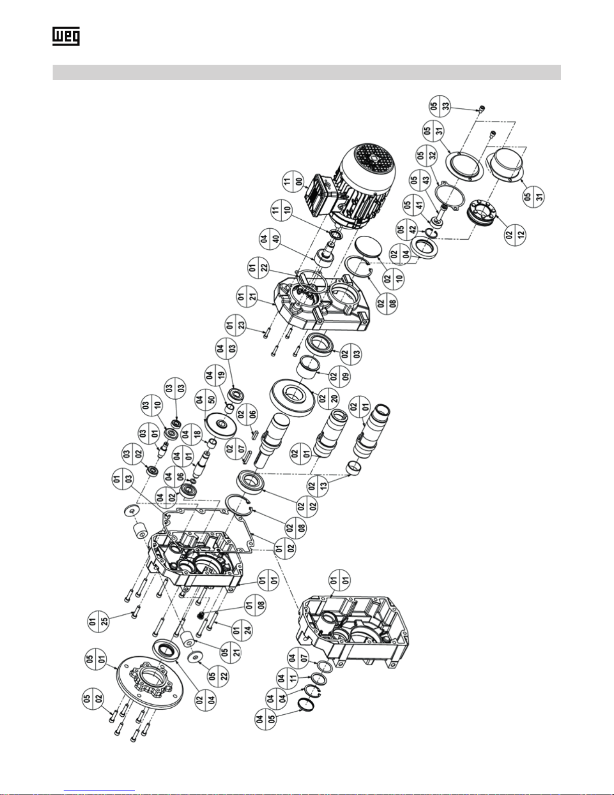
E-12 | WG20 Geared Motors
6.2. Basic design principles parallel shaft gear unit F
Gear sizes F02 to F05
Page 13

WG20 Geared Motors | E-13
Gear sizes F06 to F07
Page 14
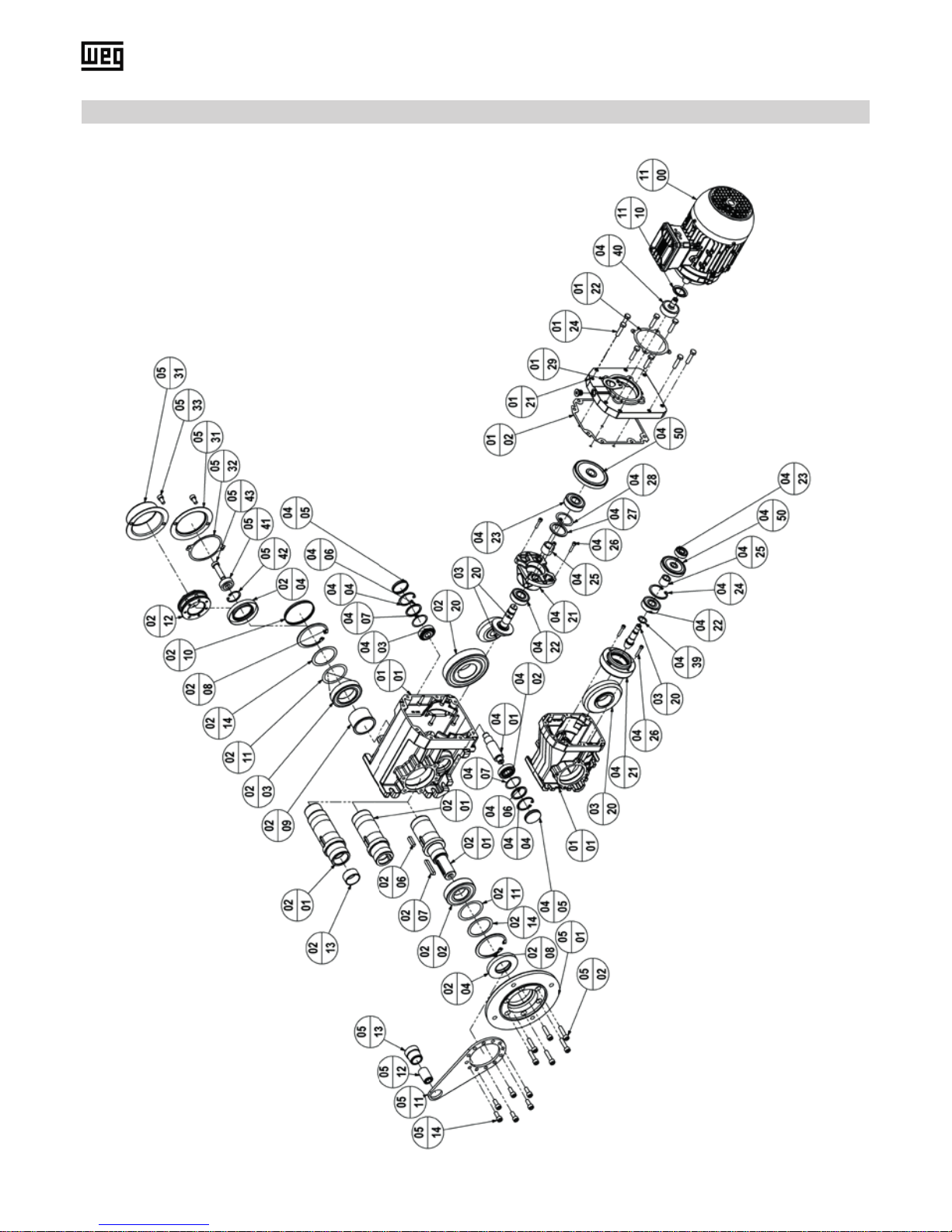
E-14 | WG20 Geared Motors
6.3. Basic design principles helical bevel gear unit K
Gear sizes K02 to K05
Page 15

WG20 Geared Motors | E-15
Gear sizes K06 to K07
Page 16

E-16 | WG20 Geared Motors
7. Mechanical installation
7.1. Preparatory work gear unit
7.1.1.Inspecting the gear unit
7.1.2.Mounting position
7.1.3.Torque support by means of rubber buffer
7.1.4.Painting the gear unit
7.1.5.Housing surface temperature
7.2. Preparatory work motor
7.2.1.Terminal box
The gear unit must not be put into operation unless:
■ no damage caused, for example, by storage or transport, is apparent.
■ in particular, the shaft seals, cover caps, and guard hoods are not damaged.
■ no leaks or loss of oil are visible.
■ no corrosion or other indication of improper storage or storage under damp conditions is present.
■ all of the packaging materials were removed.
■ oil drain plugs and vent plugs must be fully accessible!
As a general rule, drive shafts and ange surfaces must have all corrosion protection products and dirt cleaned from them,
standard commercial solvents can be used.
The gear unit may only be operated in the specied mounting position, which may be found on the nameplate. The mounting position must not be changed during operation.
Every Urelast spring must be mounted with a pre-stressing of 2 mm (F02, F03) or 3 mm (F04, F05, F06, F07).
If the gear unit will be painted or partially repainted, make certain that the vent plug and the shaft seals are carefully masked. Remove the masking tape after the painting work is completed.
In order to prevent excessive heating of the gear unit, the following must be observed:
■ Sufcient clearance must be provided around the gear unit.
■ The cooling air for gear unit motors must be able to ow unhindered around the gear unit.
■ The gear unit must not be completely boxed in with a housing.
■ The gear units must not be exposed to hot exhaust air from other units.
No heat must be transferred into the gear unit.
It must be ensured that there are no foreign bodies, dirt or moisture in the terminal box. Open entries are to be sealed
with an O ring or a suitable at gasket so that dust and water cannot enter, whereas the terminal box itself is to be sealed
against dust and water with the original seal.
It must be ensured that the terminal box, terminal board and cable connections etc. inside the terminal box are not damaged!
ATTENTION!
The sealing lips on the shaft seals must not be allowed to come in contact with the solvent!
Material can be damaged!
WARNING!
The terminal box must be sealed so that dust and water cannot enter!
Page 17

WG20 Geared Motors | E-17
7.2.2.Checking the insulation resistance
7.2.3.Connecting the ground conductor
The insulation resistance needs to be checked prior to start-up and again after any extended periods of storage or periods
during which the equipment is not in operation!
Before you begin measuring the insulation resistance, please read the manual for the insulation resistance meter you are
going to use. Any cables of the main circuit, which are already connected, should be disconnected from the terminals in
order to carry out the insulation measurements.
Where possible, measure the minimum insulation resistance of the winding to the motor enclosure when the winding temperature is between +20 °C and +30 °C. For other temperatures, different values apply to the insulation resistance. When
taking the measurement, you must wait until the nal resistance value is reached (approximately 1 minute).
If the critical insulation resistance is less than or equal to this value, the windings must be dried or, if the fan is
removed, cleaned thoroughly and dried. Note that the insulation resistance of dried, clean windings is lower than
that of warm windings. The insulation resistance can only be properly assessed after conversion to the reference
temperature of +25 °C. If the measured value is close to the critical value, you must subsequently check the insulation resistance at appropriately frequent intervals.
The following Table 1 indicates the measuring circuit voltage together with the minimum insulation resistance and the
critical insulation resistance. Values apply at a winding temperature of +25 °C.
Also note the following points:
■ When measuring at winding temperatures other than +25 °C, the measured value must be converted to the reference
temperature of +25 °C. The insulation resistance is reduced by a factor of a half for every 10 K increase in temperature,
and it is increased by a factor of two for every 10 K decrease in temperature.
■ New, dry windings have an insulation resistance of between 100 and 2,000 MΩ, or even higher values in some cases. If
the insulation resistance is close to or below the minimum value, the cause could be humidity and/or dirt accumulation.
The windings must then be dried.
■ During operation, the insulation resistance of the windings can fall to the critical insulation resistance due to ambient
and operational inuences. Depending on the rated voltage, the critical insulation resistance for a +25 °C winding
temperature can be calculated by multiplying the rated voltage (kV) by the specic critical resistance value (0.5 MΩ/kV);
e.g. critical resistance for a rated voltage (UN) 690 V: 1000 V x 0.5 MΩ/kV = 0.345 MΩ
The grounding has to be connected in the terminal box at the place intended for this purpose and marked accordingly.
The cross-section of the ground conductor of the machine must comply with the regulations for electrical installations, e.g.
DIN EN IEC 60204-1.
During the measurement, and immediately afterwards, some of the terminals are at hazardous voltage levels and
must not be touched. Carry out a check with the power cables connected that no voltage can be applied.
Rated voltage
U
rated < 2 kV
Measuring circuit voltage 500 V
Minimum insulation resistance with new, cleaned or repaired windings 10 MΩ
Critical specic insulation resistance after a long operating time 0.5 MΩ/kV
WARNING!
ATTENTION!
Table 1: Insulation resistance
Page 18

E-18 | WG20 Geared Motors
7.3. Setting up the gear unit / geared motor
7.3.1.Gear unit ventilation
Minimum surface area „S“
of phase conductor (L1, L2, L3)
Minimum surface area
of corresponding ground connection
mm² mm²
S ≤ 16 S
16 < S ≤ 35 16
S > 35 0.5 x S
■ When installing please ensure that the unit is not exposed to any shocks or vibrations in order to avoid noise during
operation.
■ The mounting surface should be even and torsionally rigid.
■ Distortion of the gear case should also be avoided.
■ Reduce reaction torque with a torque arm or a rubber buffer kit (no rigid joints).
■ Input and output elements have to be equipped with a contact protection.
■ When installing the motor, ensure that the intake is not obstructed and air can circulate freely. Do not remove the fan
blade or cowl, or enclose the motor with a casing because in both cases, there would not be enough air for cooling and
the motor could overheat.
Gear unit with vent plug:
Oil drain plugs and vent plugs must be fully accessible!
The vent plug with transport locking device is installed at the proper position for the mounting position.
Following gear unit sizes are equipped with a vent plug:
■ C07, C08
■ F06, F07
■ K06, K07
Activating the vent valve:
The vent valve is to be activated before the unit is put into operation by completely demounting the transport
protection (rubber clip) as described below.
Remove the rubber clip completely before start-up!
ATTENTION!
Figure 1: Information label (red) on the gear unit
Table 2: Minimum surface area
Please note the following when connecting-up:
■ The contact surface must be clean and bright, and protected with a suitable anti-corrosion agent, e. g. acid-free Vaseline.
Page 19

WG20 Geared Motors | E-19
7.3.2.Geared motor with backstop
7.3.3.Gear unit with solid shaft
7.3.4.Installation and demounting of hollow-shaft gear units
The backstop allows the operating in only one rotating direction. The free rotating direction is marked with a rotating direction arrow at the output of the gear or on the ventilation cover of the motor.
A start-up of the motor with full power consumption against the locking direction of the gear will lead to destruction
or damage of the backstop.
The free rotating direction has to be checked before the start-up.
Geared motor with a backstop at the motor:
Using gears with backstop, the rotating direction of the e-motor and the mains are to be detected with a meter. Mind the
rotating direction arrow on the housing! On motors, which are winded 400/690 Volt, the rotating direction can be detected
through a short-time start-up in star connection.
The output shafts are manufactured with a diameter of 50 mm in ISO k6 tolerance class and beginning at a diameter 55
mm in ISO m6 tolerance class.
All output shafts are equipped with DIN 332 tapped centre holes that are used to tighten the transfer elements.
All output shafts are provided with a corrosion protection product upon delivery. This product must be removed with a
conventional solvent.
■ The solvent must not be allowed to come into contact with the shaft seals!
■ Make certain to prevent all impacts and mechanical shocks on the end of the shaft since the output bearing
system can be damaged.
■ Mechanical drive elements that apply radial forces to the output shaft must be installed as close as possible to the
output shaft bearings!
■ Add-on power transfer elements should balance and must not cause any unacceptable radial or axial forces
(see Catalogue for acceptable values).
Concerning the design of the customer’s shaft please mind the construction references in the latest geared motor
catalogue.
Assembling: (see Figure 2 and Figure 3)
The hollow-shaft gear units must always be installed in such a way that no axial forces are applied to the output shaft
bearing system.
1. Check the machine shaft (3) on possible damages like e.g. notches or upsettings.
2. Clean the customer’s machine shaft (3) thoroughly before the mounting.
ATTENTION!
ATTENTION!
ATTENTION!
Gear drives lacking a vent plug:
Sealed-design gear drives are supplied without a vent plug.
This applies to the following gear unit types:
■ C00, C01, C03, C05, C06
■ F02, F03, F04, F05
■ K02, K03, K04, K05
Page 20

E-20 | WG20 Geared Motors
2
3
1
6
5
4
(1) Threaded rod + hex nut
(2) Thrust washer
(3) Customer-side machine shaft
(4) Retaining screw DIN6912
(5) Tension disc
(6) Circlip DIN472
Parts (4), (5) and (6) are included in the optional xing kit GMBSBSD.
Demounting:
1. Loosen the xing bolt (4). Remove the complete xing set and, if existing, the distance tube.
2. Put the pressure disc (11), jack nut (10) and circlip (6) into the hollow shaft.
3. Screw in the xing bolt (9). Through tightening of the screw you are pressing the gear off the machine shaft (3).
3 8111069
(3) Customer's shaft with tapped centre hole as per DIN332, sh.1
(6) Circlip DIN 472
(8) Hollow shaft
(9) RetainingscrewDIN933(tocustomerspecication,lengthaccordingtomachineshaftlength)
(10) Jack nut
(11) Thrust washer
Figure 2: Tightening the customer shaft Figure 3: Mounting the customer shaft using a mounting set
Figure 4: Demounting the customer shaft with or without contact shoulder
3. Before tightening the hollow-shaft gear unit onto the machine shaft, paint the surface of the machine shaft with lubricating paste (3) such as Klüber Paste 46MR401.
4. Mount the drive onto the machine shaft (4, 5). An additional distance tube is required for a customer’s shaft without
contact shoulder.
5. Implement the optionally obtainable xing set into the hollow shaft and secure the customer’s shaft axial with the
locking bolt (4). Screw tightening torque see Table 5 on page E-38.
Page 21

WG20 Geared Motors | E-21
7.3.5.Installation and demounting of shrink disks
Theshrinkdiscsaresuppliedreadytoinstall.Theymustnotbetakenapartpriortotherstinstallation.Thetightening of the locking bolts without an implemented customer’s shaft can lead to a deformation of the hollow shaft.
.
Assembling (see Figure 5):
1. Remove the possibly existing cover cap.
2. Loosen the locking bolts (3) with just a few threads. Do not screw them out completely!
3. Thoroughly degrease the entire hollow shaft boring (2, grey area). It must be ABSOLUTELY free of grease!
4. Thoroughly degrease the machine shaft (1, grey area) in the clamping area of the shrink disc. It must be ABSOLUTELY
free of grease!
5. Push the shrink disc onto the hollow shaft (2) until the outer ring of the shrink disc is ush with the hollow shaft (2). The
outer part of the hollow shaft (2) can be greased in the area where the shrink disc is tted.
6. Insert the degreased machine shaft (1) into the hollow shaft (2) so that the area of the shrink connection is fully used.
7. Slightly tighten the locking bolts (3) in sequence clockwise with several turns, so that both outer rings (5) are clamped
parallel towards each other. The number of locking bolts depends on the size of the shrink disc.
Do not tighten the locking bolts (3) „CROSSED“!
8. Tighten the locking bolts (3) with a torque key up to the indicated screwing torque (6) on the shrink disc. After the
tightening of the locking bolts (3) there has to be an even gap between the outer rings (5). If it is not the case the shrink
disc has to be mounted anew.
After installation you can sign the hollow shaft respectively the machine shaft with a marking (use a pencil) to
detect a slipping during the initial operation (under load).
1
2
4
3
6
5
1
2
3
4
5
6
7
(1) Customer-side machine shaft
(2) Hollow shaft
(3) Locking screw
(4) Inner ring
(5) Outer ring
(6) Tightening torque of the locking screws
(7) Jack nut
Demounting:
1. Undo the locking screws (3) uniformly and in sequence. Only undo each locking bolt about a quarter turn initially. Do
not remove the locking bolts completely.
2. Press the inner ring (4) off using the jack nut (7). Remove any rust beforehand that may have formed on the machine
shaft in front of the hollow shaft.
3. Remove the shrink disc from the hollow shaft (2) .
4. Step 2 only required for two-part shrink disk execution!
ATTENTION!
ATTENTION!
ATTENTION!
Figure 5: Hollow shaft with shrink disc
Page 22

E-22 | WG20 Geared Motors
7.3.6.Installation and demounting of protection cap
7.3.7.Installation of torque arms
Before being installed, the protection caps must be inspected for any damage that might have occurred during transport.
Damaged protection caps must not be installed, since they can possibly cause abrasion. All of the xing bolts are to be
used and secured by wetting them with a thread-locking adhesive (medium strength).
Bolt tightening torque see Table 5 on page E-38.
Pay attention to the direction of rotation of the hollow shaft!
The Urelast springs in the rubber buffer set are to be loaded under compression in the main working direction of rotation!
Recommended pre-loading of the Urelast spring: 2 mm (F02, F03) or 3 mm (F04, F05, F06, F07)
R L
ATTENTION!
180°
90°
270°
Clockwise Counterclockwise
Figure 6: Protection cap for hollow shaft Figure 7: Protection cap for shrink disc hollow shaft
Figure 8: Parallel shaft gear unit Figure 9:
Helical bevel gear unit K02 - K05
Figure 10:
Helical bevel gear unit K06 - K07
Possible positions of the torque arm:
K02: 90 °, 135 °, 180 °, 225 °, 270 °
K03 - K05: 90 °, 120 °, 150 °, 180 °, 210 °, 240 °, 270 °
Page 23

WG20 Geared Motors | E-23
7.3.8.Mounting of IEC/NEMA standard motors with IEC/NEMA adapters
Assembly procedure for IEC standard motors (B5) and IEC plug-in adapters I63 to I100:
Assembly procedure for NEMA standard motors (C-face) and NEMA plug-in adapters N56 to N182:
■ Clean the motor shaft and the ange surfaces of the motor and the adapter and check for damages.
■ Before installing, apply lubrication paste, e. g. Klüberpaste 46 MR 401, to the motor shaft.
■ Wet the retaining screws with thread-locking adhesive (medium strength).
■ Then place the motor on the adapter and tighten the bolts (not included) to the specied torque.
■ Use bolts with minimum property class 8.8. Tightening torque see Table 5 on page E-38.
Assembly procedure for IEC standard motors (B5) and IEC adapters I112 and I132 with geared coupling:
The correct assembly position must be observed when tting the supplied half coupling onto the motor shaft. The half
coupling has to be pushed onto the the motor shaft up to the shoulder and xed there.
■ Clean the motor shaft and the ange surfaces of the motor and the adapter.
■ Heat the half coupling to approx. 80 °C (176 °F).
■ Fit the half coupling onto the motor shaft (shaft shoulder ush with the end of the borehole).
■ Secure the key and the tted half coupling with a set pin by using thread-locking adhesive (medium strength).
■ Check that the half coupling is seated correctly.
■ The contact surface between motor and adapter has to be sealed with appropriate sealant (e.g. Loctite 510 or silicone).
This assembling step is only valid for ATEX applications.
■ Fit the motor onto the adapter. The gearing of the half coupling must t into the gearing of the coupling bush.
■ Fasten the motor onto the adapter using appropriate fastening screws (not included). Tightening torque see page E-38.
Minimum property class 8.8.
Mounting an IEC motor on the plug-in adapter
Mounting an IEC motor on the coupling adapter
Page 24

E-24 | WG20 Geared Motors
8. Check list - Gear unit
9. Check list - Motor
10. Startup
10.1. Electrical connection of the motor
Check the following before starting up the gear unit:
Information
see chapter
Check
Inspect the shipment immediately after reception for any transport damages. In some
cases, it may not be advisable to start up the unit.
Does the mounting position on the nameplate correspond to the actual mounting position? 3.1., 15.
Is the vent plug located at the correct location (in compliance with the installation position)
and freely accessible?
15.
Is the vent plug activated (rubber ap removed)? 7.3.1.
In the case of a shrink disc version: has the expansion been checked? 7.3.5.
Has the free rotating direction been checked when using a backstop? 7.3.2.
Is protection provided around rotating parts to prevent contact with them?
Check the following before starting up the motor:
Informationen
siehe Kapitel
Check
Check that the mains voltage and frequency correspond to the data on the motor rating
plate?
All connections have been made properly (motor connection, ground conductor, etc.)? 7.2.3.
Is the direction of rotation of the motor/geared motor correct? 10.2.
Has the free rotating direction been checked when using a backstop? 7.3.2.
Is the terminal box dust and watertight? 7.2.1.
Is a motor circuit breaker installed? 10.1.
Is all motor protection equipment active and set for the rated motor current?
Has the insulation resistance been checked? 7.2.2.
Optional anti-condensation heating is switched off? 18.1.
Optional forced cooling is connected to an external power supply? 18.3.
The mains voltage and the mains frequency must match the data on the nameplate. Voltage deviations of ± 5 % and/or
frequency deviations of ± 2 % are allowable..
Connect the motor only as shown in the wiring diagram included in the terminal box of the motor.
The wiring diagram for the motor series 11 and 22 is available in this manual on page E-33.
Connections must be made in such a way as to ensure that a permanently safe electrical connection is maintained (no
protruding wire ends); use the corresponding cable end pieces.
ATTENTION!
Page 25

WG20 Geared Motors | E-25
11. Operation
10.2. Direction of rotation
10.3. Oil level in the gear unit as delivered
The standard motors are suitable for clockwise and counter-clockwise rotation. Connection of the power cables in the
phase sequence L1, L2, L3 to U1, V1, W1 results in clockwise rotation (looking at the shaft end on the drive side).
If two connections are interchanged, this results in counterclockwise rotation (e.g. L1, L2, L3 to V1, U1, W1).
The proper oil level for the mounting position is designed by the plant. See gear unit nameplate for the
precise amount of oil to add.
Gear units that are ordered without oil lling are supplied with internal rust proong consisting of anti-corrosion oil. The
anti-corrosion oil can however be mixed with the recommended lubricant indicated on the nameplate. This means that the
unit does not have to be ushed before lling with oil.
If the gear unit is opened, for example: to make repairs, it must be lled with the correct lubricant in the correct amount as
stated on the nameplate before being put back into service. For lubricants see page E-28.
During the operation, the gear unit must be tested under maximum load for:
■ unusual noises,
■ vibrations and unusual oscillations,
■ smoke formation,
■ leaks.
■ With shrink disc types: After demounting the cover cap, check whether any relative movement has occurred between
the hollow shaft and the machine shaft. Then reinstall the cover guard.
■ Maximum gear housing temperature 90 °C.
Gear housing temperature:
During the operation, the surface temperature must be measured in the maximum operating condition. The max. surface
temperature is reached in about 3 hours, and it must not exceed 90°C.
The surface temperature shall be measured with standard commercially available temperature-measuring instruments.
The drive must be shut down if any abnormalities relative to the items listed above have been noted upon
inspection. Contact the producer.
A motor circuit breaker or contactor with an overcurrent relay should be installed to prevent the motor winding from
burning out. Fuses do not stop the motor overloading, but merely protect the power cables or switchgear from
damage in the event of a short circuit. Before energizing the motor, always make sure that the optional anti-condensation heating is switched off.
ATTENTION!
ATTENTION!
A change in the mounting position must not be made before consulting the producer.
ATTENTION!
ATTENTION!
Page 26

E-26 | WG20 Geared Motors
Incorrect work on the gear or motor can lead to damages. Should errors emerge at the gear or gearbox,
the drive has to be stopped immediately!
Malfunction Possible cause Settling
Unusual, even operating noise. Bearing damage, gearing damage. Consult the producer.
Unusual, uneven operating noise. Foreign object in the oil. Perform an oil change.
Movement of the gear unit during
switch-on.
Gear unit xation has loosened.
Tighten the xing bolts and nuts with
prescribed screwing torque.
Change damaged xing bolts and
nuts.
Rubber buffer set at the torque support is not pre-stressed or damaged.
Pre-stress the rubber buffer set correctly or change the damaged rubber
buffer set.
Gear unit gets too warm (Gear surface temp. > 90°C).
Too much oil. Correct the oil lling capacity.
Gear unit damage (gearing, bearing). Consult the producer.
Vent plug is defective. Change the vent plug.
Oil leakage at the gear unit or motor.
Gasket is damaged.
Check gaskets, change them if
necessary.
Gear unit is not ventilated.
Remove the transport lock at the vent
plug.
Oil leakage at the vent plug.
Too much oil. Correct the oil lling capacity.
Gear unit is operated with the wrong
type.
Mount the vent plug at the correct
position. Adjust the oil lling capacity
according to the type.
Vent plug is defect. Change the vent plug.
The gear unit output shaft does not
turn though the motor runs or the
drive shaft is being turned.
Breakage in the gear unit or shaft hub
connection disrupted.
Consult the producer.
Shrink disc connection slips through. Check the shrink disc connection.
Possible malfunctions on the gear unit:
ATTENTION!
12. Malfunction
Please provide the following information if help is needed:
■ Data from the nameplate
■ Type of problem
■ Time the problem occurred and circumstances accompanying the problem
■ Possible cause
Page 27

WG20 Geared Motors | E-27
13. Inspection and maintenance
13.1. Inspection and maintenance intervals
Gear units of the model range C (sizes 00 to 06), F (sizes 02 to 05) and K (sizes 02 to 05) are maintenance-free, oil
change is not necessary. The gear units are executed without vent plug, there are no oil drain or oil level screws..
For special applications under difcult/aggressive ambient conditions, we recommend oil change after 10000 service hours,
nevertheless.
Gear units of the model range C (sizes 07 and 08), F (sizes 06 and 07) and K (sizes 06 and 07) need an oil change according to the maintenance periods. The gear units are executed with oil drain plugs/oil lling screws for the main mounting
positions.
For special applications under difcult/aggressive ambient conditions, please contact your service partner!
Time interval Inspection and maintenance work
monthly
■ Gear units must be checked for noise changes (run-
ning noise of the gearing and rolling bearings)
■ Check the housing temperature (max. 90°C, 194°F)
■ Visible inspection of seals for leakage (Oil leakage)
■ Remove dust deposits
every 3 months Clean the exterior of the vent plug
every half year
■ Check the rubber buffer set
■ Check the xing bolts to make certain they are tight
every 5000 service hours, no later than every 4 years
Visual check of the shaft seals; if applicable replace the
shaft seals
every 10000 service hours, no later than every 5 years
Oil change:
■ Helical gear units C07, C08
■ Parallel shaft gear units F06, F07
■ Helical bevel gear units K06, K07
every 10 years General recovery
regularly on demand (depending on outside inuences)
■ Check the air gap
■ Clean the fan wheel of the motor
13.2. Inspection and maintenance work on gear unit
No explosive atmosphere may be prevented in any maintenance or repair work. Maintenance and repair
work must only be performed by qualied specialists in the eld.
Maintenance and repair work are only to be carried out on a drive, which is in standstill with zero potential
and secured against accidental switch on.
Before beginning the work let the gear cool down! Danger of burning!
Visible inspection of seals for leakage:
Make certain that no gear oil is leaking and that no oil traces can be found. In particular, the shaft seals and locking caps,
as well as the sealing surface must be checked.
Check the rubber buffer set:
The rubber buffer set must be checked for visible damage, such as cracks on the surface, and they must be replaced in
some cases.
WARNING!
WARNING!
Page 28

E-28 | WG20 Geared Motors
14. Lubricants
If a special agreement regarding the lubricant is not reached, the gear units shall be delivered factory-lled (see table
below marked grey). The specied gear ll amount and type is stated on the gear unit nameplate. The ll amount and oil
type can be different at special applications.
The following lubricant table shows the lubricants that are approved for WG20 gear units.
For helical, parallel shaft and helical bevel gear units at ambient temperatures -10 °C to +60 °C (14 °F to 140 °F)
Do not mix different types of lubricant!
Lubricants for other ambient conditions on request. Food proofed and biodegradable lubricants on request.
ALPHA SP 220 Klüberoil GEM 1-220 N
DEGOL BG 220 Mobilgear 600 XP 220
Energol GR-XP 220 Omala S2 GX220
Gear Oil 220 F
Remove dust deposits:
Remove any layers of dust that have accumulated on the gear unit. If the gear unit design included a protection cap, remove it and clean it too. Then reinstall the protection cap (see page E-22).
Change the shaft seals:
When changing the shaft seal, make certain that, depending on the design, a sufcient deposit of grease is present between the dust lip and the sealing lip.
When using double seals, ll one-third of the space between them with grease.
Oil change:
Let the gear cool down before beginning with the work! The oil has to be warm to make a complete emptying easier (poor
ow characteristics).
1. Put an appropriate container under the air vent and oil drain plug.
2. Remove the air vent and oil drain plug.
3. Let the oil drain completely.
4. Turn the plug in again completely.
5. Fill in the prescribed amount of oil over the vent plug (oil ll capacity see gear nameplate, permitted lubricants see page
E-28).
6. Tighten the vent plug completely again.
7. Dispose the used oil according to applicable regulations.
General overhaul:
The general overhaul is to be performed by the producer or by an authorised service partner.
Adjustment of air gap: see page E-35.
Nachträgliche Lackierung: Wird das Getriebe nachträglich neu lackiert, müssen Wellen, Wellendichtringe, Montage-
ächen, Gummibauteile, Entlüftungsventile, Ölschaugläser, Typenschilder und Aufkleber frei von Farben, Lacken und
Lösungsmitteln bleiben, um Beschädigungen und Unlesbarkeit zu vermeiden.
Page 29

WG20 Geared Motors | E-29
15. Mounting positions and lubricant capacity
15.1. Helical gear units C
Mounting positions and position of venting and oil drain screw
By default, gear units are only equipped with venting and oil drain screw from gear size C07!
Lubricant capacity
Stages Type with housing in foot execution
Mounting positions
M1 M2 M3 M4 M5 M6
2
C00 0.1 l 0.3 l 0.3 l 0.3 l 0.2 l 0.2 l
C01 0.1 l 0.4 l 0.4 l 0.3 l 0.3 l 0.3 l
C03 0.3 l 0.7 l 0.6 l 0.6 l 0.5 l 0.4 l
C05 0.4 l 1.2 l 1.1 l 1.2 l 0.8 l 0.7 l
C06 0.5 l 1.6 l 1.6 l 1.5 l 1.1 l 1.0 l
C07 1.6 l 3.8 l 3.6 l 4.6 l 2.8 l 2.4 l
C08 3.4 l 7.1 l 6.7 l 8.9 l 4.7 l 5.4 l
3
C03 0.2 l 0.7 l 0.7 l 0.6 l 0.4 l 0.4 l
C05 0.3 l 1.1 l 1.1 l 1.1 l 0.7 l 0.7 l
C06 0.3 l 1.5 l 1.6 l 1.4 l 1.0 l 0.9 l
C07 1.5 l 3.6 l 3.5 l 4.4 l 2.6 l 2.4 l
C08 3.3 l 6.9 l 6.6 l 8.8 l 4.8 l 5.1 l
Stages Type with housing in ange execution
Mounting positions
M1 M2 M3 M4 M5 M6
2
C00 0.1 l 0.3 l 0.4 l 0.3 l 0.2 l 0.3 l
C01 0.2 l 0.4 l 0.5 l 0.5 l 0.3 l 0.4 l
C03 0.4 l 0.8 l 0.7 l 0.8 l 0.5 l 0.5 l
C05 0.6 l 1.3 l 1.2 l 1.5 l 0.9 l 1.0 l
C06 0.9 l 1.8 l 1.9 l 2.2 l 1.9 l 1.4 l
C07 1.6 l 3.8 l 3.6 l 4.6 l 2.8 l 2.4 l
C08 3.4 l 7.1 l 6.7 l 8.9 l 4.7 l 5.4 l
3
C03 0.3 l 0.7 l 0.7 l 0.7 l 0.5 l 0.5 l
C05 0.5 l 1.2 l 1.3 l 1.5 l 0.9 l 1.0 l
C06 0.8 l 1.7 l 1.8 l 2.1 l 1.2 l 1.3 l
C07 1.5 l 3.6 l 3.5 l 4.4 l 2.6 l 2.4 l
C08 3.3 l 6.9 l 6.6 l 8.8 l 4.8 l 5.1 l
M1
M2
M3
M4
M5M6
Position of the venting screw
Position of the oil drain screw
1) Position ange execution
2) Position foot execution
1)
2)
1)
2)
Page 30

E-30 | WG20 Geared Motors
15.2. Parallel shaft gear units F
Lubricant capacity
Stages Type
Mounting positions
M1 M2 M3 M4 M5 M6
2
F02 0.5 l 0.7 l 0.6 l 0.8 l 0.5 l 0.5 l
F03 0.8 l 1.1 l 0.7 l 1.1 l 0.8 l 0.8 l
F04 1.1 l 1.8 l 1.1 l 1.9 l 1.1 l 1.1 l
F05 2.0 l 2.3 l 1.5 l 2.8 l 1.7 l 1.8 l
F06 2.3 l 3.6 l 2.5 l 4.0 l 2.3 l 2.5 l
F07 4.9 l 6.3 l 4.2 l 8.0 l 4.4 l 4.8 l
3
F04 1.5 l 1.7 l 1.1 l 1.8 l 1.0 l 1.1 l
F05 2.3 l 2.2 l 1.4 l 2.5 l 1.6 l 1.5 l
F06 2.7 l 3.5 l 2.3 l 3.8 l 2.4 l 2.3 l
F07 5.8 l 6.2 l 3.9 l 7.7 l 4.4 l 4.5 l
Mounting positions and position of venting and oil drain screw
By default, gear units are only equipped with venting and oil drain screw from gear size F06!
M1
M2
M3
M4
M5M6
Position of the venting screw
Position of the oil drain screw
Page 31

WG20 Geared Motors | E-31
15.3. Helical bevel gear units K
Lubricant capacity
Stages Type
Mounting positions
M1 M2 M3 M4 M5 M6
2 K02 0.4 l 0.8 l 0.7 l 0.9 l 0.5 l 0.6 l
3
K03 0.4 l 1.0 l 1.2 l 1.3 l 1.0 l 1.0 l
K04 0.6 l 1.6 l 1.9 l 2.1 l 1.7 l 1.7 l
K05 0.8 l 2.1 l 2.6 l 3.1 l 2.1 l 2.2 l
K06 0.8 l 2.0 l 2.7 l 3.0 l 2.2 l 2.4 l
K07 1.5 l 3.5 l 4.3 l 5.3 l 3.7 l 4.1 l
Mounting positions and position of venting and oil drain screw
By default, gear units are only equipped with venting and oil drain screw from gear size K06!
M1
M2
M3
M4
M5M6
Position of the venting screw
Position of the oil drain screw
Page 32

E-32 | WG20 Geared Motors
16. Position of terminal box and cable entry
17. Terminal board connection
Figure 11: Possible terminal box positions 1 to 4 (standard position on side 1) and cable entries I to IV (standard position
on side I)
Rated voltage series 11N, 11P (IEC frame sizes 63 to 100)
Possible connection Rated power P
N
Increased rated power 1.2 x P
N
VSD operation
Delta
220 - 230 - 240 V at 50 Hz -
400 V,
87 Hz
220 - 265 - 277 V at 60 Hz 254 - 265 - 277 V at 60 Hz
Delta - Delta
110 - 115 - 120 V at 50 Hz -
230 V,
100 Hz
110 - 132 - 138 V at 60 Hz 127 - 132 - 138 V at 60 Hz
Star
(Basic connection)
380 - 400 - 420 V at 50 Hz -
400 V,
100 Hz
380 - 460 - 480 V at 60 Hz 440 - 460 - 480 V at 60 Hz
Star - Star
190 - 200 - 210 V at 50 Hz -
460 V,
120 Hz
190 - 230 - 240 V at 60 Hz 220 - 230 - 240 V at 60 Hz
Rated voltage series 11P (IEC frame sizes 112 to 132) and 22P (IEC frame sizes 160 to 180)
Possible connection Rated power P
N
Increased rated power 1.2 x P
N
VSD operation
Delta
(Basic connection)
380 - 400 - 420 V at 50 Hz -
400 V,
100 Hz
380 - 460 - 480 V at 60 Hz 440 - 460 - 480 V at 60 Hz
Delta - Delta
190 - 200 - 210 V at 50 Hz 190 - 230 - 240 V at 60 Hz 220 - 230 - 240 V at 60 Hz
Star
660 - 690 - (730) V at 50 Hz -
460 V,
120 Hz
660 - (796) - (830) V at 60 Hz (760) - (796) V at 60 Hz
Star - Star
330 - 346 - 365 V at 50 Hz 330 - 400 - 415 V at 60 Hz 380 - 400 - 415 V at 60 Hz
1
2
3
4
I
II
III
IV
1
2
3
4
I
II
III
IV
Side B Side A
1
2
3
4
I
II
III
IV
Side A Side B
C:
F:
K:
Page 33

WG20 Geared Motors | E-33
The following connection diagram is valid for modular system motors of the series 11N and 11P in frame sizes 63 to 132
and 22P in frame sizes 160 to 180.
Figure 12: Terminal board connection - motor series 11N, 11P and 22P
Thread Tightening torque Ma [Nm]
M4 0.7 - 1.0
M5 1.6 - 2.2
M6 2.2 - 3.5
M8 6 - 8
M10 10 - 14
Table 3: Tightening torque for terminal box
Bimetal switch (2TB1/2TB2) only available for motor series 11
Page 34

E-34 | WG20 Geared Motors
18. Optional motor devices
18.1. Anti-condensation heating
18.2. Drain
18.3. Forced cooling
Brake, encoder, temperature controller, anti-condensation heating, forced ventilation, etc. are present only on special order.
Additional devices are to be connected according to the valid wiring diagrams.
Under certain climatic conditions, an anti-condensation heater may be required e. g. when there are great uctuations in
temperature or the motor is at rest in a humid atmosphere. For heater connection, see the motor terminal box.
Before energizing the motor, always make sure that the (optional) anti-condensation heating is switched off.
If motors are subject to great uctuations in temperature or extreme climatic conditions, humid air can condense inside the
machine. We recommend using a drain.
■ Open the drain depending on the environment and operating conditions. Afterwards, close the drain plug.
■ Before installing motors with drain, check that the mounting position is correct!
Figure 13: Detail of the drain plug position on drive endshield
■ The forced cooling must be connected according to the wiring diagram below (see also in forced cooling
terminal box).
■ If the motor is operated with a frequency inverter, it´s not allowed to connect the forced cooling to the frequen-
cy inverter. Connect the forced cooling to an EXTERNAL power supply.
IEC frame size Phases / Connection
Voltage range [V]
50 Hz 60 Hz
63 - 180
3~ / Star 346 - 525 380 - 575
3~ / Delta 200 - 303 220 - 332
1~ / Delta Steinmetz 230 - 277 230 - 277
WARNING!
ATTENTION!
ATTENTION!
Rubber drain plug closed Rubber drain plug open
Page 35

WG20 Geared Motors | E-35
18.4. Temperature controller Bimetal switch „NC contact“ (TH)
18.5. PTC Thermistor protection (TF)
18.6. Brake
U1 = black V1 = light blue W1 = brown
U2 = green V2 = white W2 = yellow
Thermostats have small bimetallic strips that make or break a contact when the critical temperature is reached. The break
contact opens the eld circuit and disconnects the power supply to the motor. Thermostats are only available for motor
series 11 (frame sizes 63 to 132).
Block terminal designation in the terminal box: 2TB1 / 2TB2 (see page E-33)
PTC thermistors are semi-conductors whose electrical resistance increases dramatically when the critical temperature is
reached.
In addition to the PTC thermistor, a control unit is also required. The relay in the tripping unit has a changeover contact,
which can either be used to open the excitation circuit in the motor contactor or trigger a warning signal.
Block terminal designation in the terminal box: 2TP1 / 2TP2 (see page E-33)
The single-disc brake is released electrically. The brake is applied mechanically when the voltage is switched off.
At delivery the brakes are adjusted to the brake torque.
Connecting the brake:
Connect the brake control system according to the circuit diagram supplied with the brake.
Maintenance:
DThe spring-loaded brakes hardly need any maintenance. The air gap "a" must be checked periodically to ensure safe
brake release. Adjust air gap "a" to the gures given in Table 4 if necessary.
Brake torque [Nm] 2 5 10 20 40 60 100 150 250
a (normal) [mm] 0.2 0.2 0.2 0.3 0.3 0.3 0.4 0.4 0.5
a (maximum) [mm] 0.6 0.6 0.7 0.8 0.9 1.0 1.1 1.1 1.2
Table 4: Brake air gap
Adjustment of the air gap (see Figure 14):
1. Loosen the three xing bolts (11) in a half turn.
2. Turn the hollow screws (9) counter-clockwise into the magnetic case (10).
3. Turn the three xing bolts (11) clockwise until the nominal air gap (siehe Tabelle 4) between the magnetic case (10) and
armature disc (8) is reached.
4. Turn the three hollow screws (9) again clockwise out of the magnetic case (10) and retighten the xing bolts (11). Con-
trol the air gap “a” with a feeler gauge on evenness and make a correction if necessary.
Star Connection Delta Connection Delta Steinmetz Connection
Page 36

E-36 | WG20 Geared Motors
18.6.1.Manual brake release
18.6.2.Locking device for the manual release lever
18.6.3.Rectier
1
2
3
4
5
6
7
8
9
10
11
12
13
14
15
16
17
18
(1) Brake endshield
(2) Key
(3) Motor shaft
(4) Dust protection ring
(5) Friction plate
(6) Gear hub
(7) Manual release lever (optional)
(8) Brake disc with friction linings
(9) Sleeve screws
(10) Magnetic case
(11) Socket cap screws
(12) Key
(13) Brake shaft extension
(14) Fan
(15) Retaining ring
(16) Socket cap screw
(17) Fan cover screws
(18) Fan cover (brake execution)
It is used to lift the brake in case of a loss of power supply. By pressing the lever, the anchor plate is pulled to the magnet
and the brake is lifted.
For safety reasons the adjustment of the manual release must not be changed.
In case of service, the manual brake release can be xed with a locking device.
The motor may only be taken into operation after having deactivated the locking device.
Brake motors will be delivered as standard with connected rectier for AC-side switching. For DC-side switching the bridge
between terminals 5 and 6 must be removed and a switching contact must be connected.
Start-up of motor only with connected brake. (Check!)
ATTENTION!
ATTENTION!
ATTENTION!
Figure 14: Exploded view brake
Page 37

WG20 Geared Motors | E-37
18.6.4.Encoder
Figure 15: Rectier
~~
1 2 3 4 5 6
-
+
Power supply:
The DC brake coil is normally supplied with power from a rectier installed in the motor terminal box. The rectiers are equipped with varistors to protect them against overvoltage. Max. ambient temperature for rectiers is +80 °C.
For starting frequency above 1/s, contact us for rectier loading capacity!
The braking system is connected with a rectier installed in the terminal box in accordance with the enclosed circuit dia-
gram.
Half-wave rectier (standard version) - Connection:
■ AC voltage 100% e.g. 400 V~
■ DC voltage 45% e.g. 180 V=
Bridge rectier - Connection:
■ AC voltage 100% e.g. 230 V~
■ DC voltage 90% e.g. 207 V=
If a brake motor is operated with a frequency converter, connect the brake coil to an external power
supply.
This encoder is a precision measuring instrument. Always observe the information and instructions of the datasheet to
ensure trouble-free function and to maintain warranty claims.
Please observe absolutely the following points:
■ It is not permissible to dismantle the encoder entirely or in part or to modify it.
■ Do not alter the shaft (by grinding, sawing, drilling, etc.), otherwise the accuracy of the encoder and the reliability of
bearing and seal will suffer.
■ Never align the instrument with a hammer.
■ It is imperative to avoid impact loads.
■ Observe maximal radial and axial loads to the encoder shaft under any circumstances.
■ Do not connect encoder and drive rigidly to one another at shafts and anges.
■ Never use the assembled encoder to lift the drive-unit.
■ Never step onto the encoder.
ATTENTION!
Connection to terminal board
(AC, V~)
Contact for DC switching
Brake
Type Voltage Pulses Output signal
Kübler 5020 10 - 30 V 1024 HTL
Kübler A02H (Heavy Duty) 10 - 30 V 1024 HTL
Technical Data Standard Encoder:
Page 38

E-38 | WG20 Geared Motors
19. Table of Tightening Torques
Pin denition standard encoder:
SIGNAL GRD B
INV
+ UB
Sens
0 0
INV
A A
INV
- B - 0 V
0 V
Sens
+UB U
AS
KÜBLER
M23 x 1
Can
1 2 3 4 5 6 7 8 9 10 11 12 -
PVC cable PH PK
BU/
RD
BU RD GN YE - GY - WH
GY/
PK
BN -
PUR cable
HT cable
PH PK BN* BU RD GN YE - GY - WH° WH* BN° -
Code Colour Code Colour Code Colour Code Colour Code Colour
BK Black GN Green RD Red YE Yellow
PH
Shield is
attached to con-
nector housing
BN Brown GY Grey VT Violet * Thin cable
BU Blue PK Pink WH White ° Thick cable
Screw connections are laid out for screw property class 8.8:
Table 5: Tightening Torques
Tightening torque Ma [Nm] - tolerance +10 %
Thread
Screw property class
8.8
Screw property class
10.9
Screw property class
12.9
M5 5.5 8.0 10
M6 10 14 18
M8 25 33 43
M10 45 65 80
M12 75 105 135
M16 190 270 340
M20 380 530 670
M24 650 900 1150
M30 1300 1800 2300
20. Disposal
Mind the current national regulations for the disposal.
Oils and greases or oil and grease containing wastes make up a high hazardous potential for the environment. Thus,
ensure a professional disposal!
Geared motors units Material
Gear housing, housing parts (input cover, adapters,
anges etc.)
Aluminium, Grey cast iron
Gear inner parts (tooth wheels, keys, shafts) Steel
Shaft sealing rings Elastomer with steel
Flat seals Asbestos-free
Gear oil Additivated mineral oil
Page 39

WG20 Geared Motors | E-39
21. Declaration of incorporation
Declaration of Incorporation
in terms of the EC Machinery Directive 2006/42/EC, Annex II B
Product: Classification:
Helical geared motors WG20 C.
Parallel shaft geared motors WG20 F.
Helical bevel geared motors WG20 K.
Producer: WATT DRIVE Antriebstechnik GmbH
Wöllersdorfer Straße 68
2753 Markt Piesting - Austria
Authorized person for the compilation of the technical documents:
Norbert Reisner - Wöllersdorfer Straße 68 - 2753 Markt Piesting
The producer herewith declares referring to the above named incomplete machines that:
They meet the basic requirements of the Direction 2006/42/EC as far as possible.
The technical documents have been compiled according to Annex VII Chapter B.
The special technical documents for partly completed machinery have been created and can be made
available to the national authorities in response to a reasonable request.
Their commissioning is prohibited until they have been implemented according to the mounting
instruction and an EC Declaration of Conformity for the whole machine according to Direction
2006/42/EC is submitted.
Relevant applicable provisions:
EC Machinery Direction 2006/42/EC
Security for Machinery EN ISO 12100:2010
Electric Equipment EN 60204 -1:2006 + A1:2009 + AC:2010
Separating Safety Equipment EN ISO 14120:2015
Safety Distances EN ISO 13857:2008
Rotating Electrical Machines
EN 60034-1:2010 + AC:2010, EN 60034-2-1:2007, EN 60034-5:2001 + A1:2007,
EN 60034-6:1993, EN 60034-7:1993 + A1:2001, EN 60034-8:2007 + A1:2014,
EN 60034-9:2005 + A1:2007, EN 60034-11:2004, EN 60034-12:2002 + A1:2007,
EN 60034-14:2004 + A1:2007, EN 60034-30:2009
The original version of the mounting instruction belonging to the incomplete machine is in German.
.
Markt Piesting, 26.04.2017
Place and date of issue Klaus Sirrenberg - Managing Director
Page 40

E-40 | WG20 Geared Motors
22. EU declaration of conformity ATEX 2014/34/EU
EU - Declaration of Conformity
in terms of the EU Directive on Explosion Protection 2014/34/EU
Products of the geared motor series WG20/MAS: Classification:
Helical geared motors C./H.
Shaft mounted geared motors - /A.
Parallel shaft geared motors F./F.
Helical worm geared motors - /S.
Helical bevel geared motors K./K.
Angle parallel shaft geared motors - /C.
Producer: WATT DRIVE Antriebstechnik GmbH
Wöllersdorfer Straße 68
2753 Markt Piesting - Austria
The manufacturer declares the sole responsibility for the above-mentioned products for:
Zone 2 and 22
Device Group II
Category 3G and 3D
Marking:
II 3G Ex h IIC T4 Gc / II 3G Ex nA IIC T3 Gc
II 3D Ex h IIIC 125°C Dc / II 3D Ex tc IIIC T125°C Dc
Applied harmonized standards:
EN 80079-36:2016
EN 80079-37:2016
EN 60079-0:2012
EN 60079-15:2010
EN 60079-31:2014
Markt Piesting, 12.04.2018
Place and date of issue Klaus Sirrenberg - Managing Director
Page 41

WG20 Geared Motors | E-41
23. EU declaration of conformity: low voltage directive 2014/35/EU
EU - Declaration of Conformity
In terms of the Low Voltage Directive 2014/35/EU
Product:
Asynchronous Three Phase motors with cage rotor
Single Phase Induction motors with cage rotor
IEC Motor Size: 56 – 355
Series:
WA_ 7WA_ 70 WA_ 7B WA_ 2A WA_ 2B WA_ 3A WA_ 3B WA_ 3C WA_
WP_ 7WP_ 70 WP_ 7B WP_ 2A WP_ 2B WP_ 3A WP_ 3B WP_ 3C WP_
11N 11H 11P M31_ M32_ M33_
Producer: WATT DRIVE Antriebstechnik GmbH
Wöllersdorfer Straße 68
2753 Markt Piesting - Austria
This declaration of conformity is issued under the sole responsibility of the manufacturer.
The object of the declaration described above is in conformity with the relevant Union harmonisation
legislation:
Low Voltage Directive 2014/35/EU
ErP Directive 2009/125/EC
1)
EMC Directive 2014/30/EU
Electrical Equipment EN60204-1:2006 + A1:2009 + AC:2010, EN 60204-11:2000 + AC:2010
Rotating Electrical Machines
EN 60034-1:2010 + AC:2010, EN 60034-2-1:2007, EN 60034-5:2001 + A1:2007,
EN 60034-6:1993, EN 60034-7:1993 + A1:2001, EN 60034-8:2007 + A1:2014,
EN 60034-9:2005 + A1:2007, EN 60034-11:2004, EN 60034-12:2002 + A1:2007,
EN 60034-14:2004 + A1:2007, EN 60034-30:2009
1)
Products that are covered by this ErP Directive meet the requirements of Regulation (EC) No. 640/2009
from July 22, 2009 resp. Regulation (EU) No. 4/2014 from January 6, 2014.
Markt Piesting, 26.04.2017
Ort und Datum der Ausstellung Klaus Sirrenberg - Managing Director
Page 42

E-42 | WG20 Geared Motors
Page 43

WG20 Geared Motors | E-43
Page 44

Watt Drive Antriebstechnik GmbH – WEG Group
Wöllersdorfer Straße 68, 2753 Markt Piesting, Austria
Phone: +43 (0)2633 / 404-0, Fax: +43 (0)2633 / 404-220
E-Mail: watt@wattdrive.com
Web: www.wattdrive.com
Code: 50069628 | Rev.: 02 | Date (M/J): 09/2018
Language: English, Original document: German
The values shown are subject to change without prior notice.
 Loading...