

WEG SSW900-CRS485-W Operation Manual
Motors | Autom ation | Energy | Transmi ssion & Distribu tion | Coatings
RS485 Communication Plug-in Module
Módulo Plug-in de Comunicación RS485
Módulo Plug-in de Comunicação RS485
SSW900-CRS485-W
Installation, Configuration and Operation Guide
Guía de Instalación, Configuración y Operación
Guia de Instalação, Configuração e Operação
Document: 100 03988739 / 00
13473747
1 INFORMAÇÕES DE SEGURANÇA
1.1 AVISOS DE SEGURANÇA
NOTA !
Somente utilizar o módulo plug-in de comunicação RS485
(SSW900 -CRS485-W ) nas soft-star ters WEG séri e SSW900.
Recomenda-se a l eitura do m anual do us uário da SSW 900
antes de ins talar ou operar e sse acessório.
1.2 RECOMENDAÇÕES PRELIMINARES
PERIGO!
Sempre descon ecte a alimentaç ão geral antes de c onectar ou
descone ctar os acessór ios da soft- star ter SSW900.
Aguarde pelo me nos 3 minutos pa ra garantir a de senergiz ação
completa da soft-starter.
ATENÇÃO!
Os cartões elet rônicos po ssuem com ponentes s ensíveis a
descarg as eletros táticas. Nã o toque direta mente sobr e os
componentes ou conectores.
2 INFORMAÇÕES GERAIS
Este guia or ienta na ins talação, c onfiguraç ão e operaç ão do módulo
plug-in de comunicação RS485 (SSW900-CRS485-W).
NOTA !
O módulo conectado no slot 1 deve ser diferente do conectado
no slot 2. Não é possível utilizar simultaneamente dois módulos
idêntic os nos slots 1 e 2.
3 CONTEÚDO DA EMBALAGEM
Ao recebe r o produto, verifica r se a embalagem con tém:
Acessório em em balagem anti-e stática.
Guia de instalação, configuração e operação.
4 INSTALAÇÃO DO ACESSÓRIO
O acessório SSW900-CRS485-W é incorporado de forma simples e
rápida à soft-starter SSW900, u sando o con ceito "plug a nd play". Os
procedi mentos abai xo devem ser s eguidos p ara a corret a instalaç ão e
colocação em funcionamento:
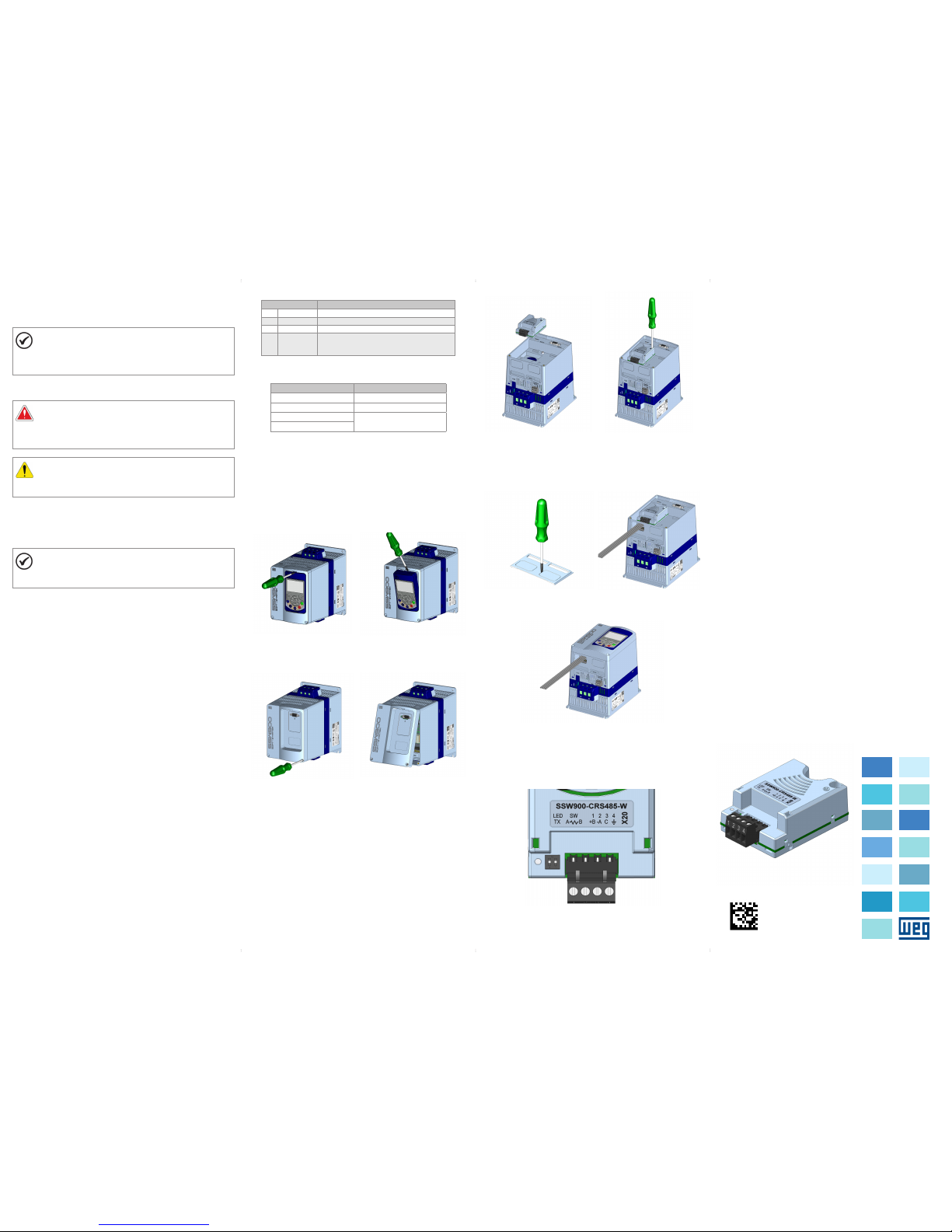
1. C om o controle da s oft-st arte r SSW900 de senergizad o, retire a tampa
frontal (Figura A1 (a) a (d)).
2. Encaixe o aces sório a ser i nstalado e m um slot conforme indi cado na
Figura A1 (e).
3. Fixar o paraf uso de aterramento d o acessório confo rme indicado pela
Figura A1 (f).
4. Remova a tampa do furo d e passage m dos cabos c onforme in dicado
pela Figura A1 (g) e conecte os cabos de sinal no conector do acessório
(Figura A1 (h)).
5. Recolo que a tampa fronta l (Figura A1 (i)).
6. Energize o c ontrole da so ft-s tar ter SSW9 00 e verifiq ue se o acessó rio foi
identificado corretamente. O modelo do acessório conectado é indicado
em S3.5.1 e S3.5.2.
5 CONFIGURAÇÕES
As conexõe s do acessó rio SSW90 0-CRS48 5-W devem se r feitas no
conector conforme Tabe la 1. O a cessóri o possui ch aves que pod em ser
ativadas p ara habili tar o resis tor de termin ação confo rme Tab el a 2. O
conectore do acessório e a chave para habilitar o resistor de terminação
são apres entados na Figura A2.
Tabela 1: Sinais d o conector RS485 (X 20)
Conector Descrição
1 + B RxD/TxD positivo
2 - A RxD/TxD negativo
3 C 0 V isolado do circuito RS485
4 Te rra Conexão co m o terra de proteção, nor malmente
utilizad o para ligação da bli ndagem do cabo de
comunicação
Tabela 2: Conf igurações da chave ( SW) de habilitaç ão do resistor de
terminação
Ajuste das Chaves Opção
SW.1 = OFF e SW.2 = OFF Terminação RS485 desligada
SW.1 = ON e SW.2 = ON Terminação RS485 ligada
SW.1 = OFF e SW.2 = ON
Combinação não permitida.
SW.1 = ON e SW.2 = OFF
6 OPERAÇÃO
Para detalhes relacionados à programação e operação do produto
utiliza ndo o acess ório SSW90 0-CRS4 85-W, consulte o m anual de
program ação, disponível e m www.weg.net.
Português
APPENDIX A - FIGURES
ANEXO A - FIG URAS
(a) Remova l of the HMI
(a) Remove t he HMI
(a) Remova a H MI
(b) Remova l of the HMI
(b) Remoc ión de la HMI
(b) Remoç ão da HMI
(c) Remove t he screws from t he
front cover
(c) Retir e los tornill os de la tapa
frontal
(c) Retir e os parafuso s da tampa
frontal
(d) Remova l of the front co ver
(d) Remoción de la tapa frontal
(d) Remoç ão da tampa fro ntal
(e) Accessory connection
(e) Conexión del accesorio
(e) Conexã o de acessóri o
(f) Tig hten the scre ws of the
access ory (Torque: 0 .51 N/m)
(f) Apr iete los torn illos del
acceso rio (Torque: 0. 51 N/m)
(f) Ape rte os paraf usos do
acessó rio (Torque: 0. 51 N/m)
(g) Remove t he cover hole
(g) Remue va la tapa del agu jero
(g) Remova a t ampa do furo
(h) Connect the signal cables
(h) cone cte los cable s de señal
(h) Cone cte os cabos de s inal
(i) Accessory connection
(i) Conexión del accesorio
(i) Conexão do acessório
Figure A1: (a) to (i): Installati on of accessory
Figura A1: (a) a (i): Instalaci ón de accesorio
Figura A1: (a) a (i): Instalação d e acessório
Figure A2: Connector and switch location
Figura A2: Localización del conectador y interruptores
Figura A2: Localização do co nector e chave
1 SAFETY INFORMATION
1.1 SAFETY WARNINGS
NOTE!
Only use the RS485 communication plug-in module
(SSW900 -CRS485-W ) on WEG SSW900 se ries soft-st arters.
It is recommende d reading the SSW90 0 user’s manual befo re
installing or operating this accessory.
1.2 PRELIMINARY RECOMMENDATIONS
DANGER!
Always disconnect the general power supply before connecting
or disconnecting the accessories of the SSW900 soft-starter.
Wait for at least 3 min utes for the ful l discharge of t he soft-star ter.
ATTENTION!
Electronic boards have components sensitive to electrostatic
discharges. Do not touch directly on components or connectors.
2 GENERAL INFORMATION
This guide provides directions for the installation, configuration
and opera tion of the RS4 85 communication plug-in module
(SSW900-CRS485-W).
NOTE!
The module connected to slot 1 must be different from the one
connected to slot 2. It is not possible to use simultaneously two
identic al modules on slots 1 a nd 2.
3 PACKAGE CONTENT
Upon receiving the product, check if the package contains:
Accessory in a nti-static packag e.
Installation, configuration and operation guide.
4 INSTALLATION OF THE ACCESSORY
The SSW90 0-CRS485-W is eas ily connected to the SS W900 soft-starter
by means of th e plug-and -play conc ept. The proc edures be low must be
observed for the proper installation and start-up:
1. With the S SW900 soft-star ter control powere d down, remove the fron t
cover (Figure A1 (a) to (d)).
2. Fi t the accessor y to be installed into a s lot, as shown in Figure A1 (e).
3. Faste n the grounding s crew of the access ory, as shown in Figure A1 (f).
4. Remove the c over of the cab le passag e hole, as ind icated in
Figure A1 (g), and connect the signal cables to the connector of
the acces sory (Figure A1 (h)).
5. Put the fro nt cover back in plac e (Figure A1 (i)).
6. Power up the SS W900 soft-st arter cont rol, and check t hat the acces sory
was corre ctly ident ified. Th e model of the a ccessor y conne cted is
indicate d in S3.5.1 and S3.5.2.
5 CONFIGURATIONS
The conne ctions of the SSW9 00-CRS485-W a ccessory mus t be made as
indicated in Table 1. The accesso ry has switches tha t can be activated to
enable the termination resistor according to Table 2. The accesso ry
connectors and the switch to enable the termination resistor are shown in
Figure A2.
Table 1: Signals of th e RS485 (X20) conne ctor
Connector Description
1 + B RxD/TxD positive
2 - A RxD/TxD negative
3 C 0 V isolated fr om the RS485 circui t
4 Protective
earth
Connection to the protective earth,
normally used to connect the shield of the
communication cable
Table 2: Config urations of the switc h (sw) that enables the te rmination resi stor
Switch Setting Option
SW.1 = OFF and SW.2 = OFF RS485 term ination off
SW.1 = ON and SW.2 = ON RS485 term ination on
SW.1 = OFF and SW.2 = ON
Combination not allowed
SW.1 = ON and SW.2 = OFF
6 OPERATION
For detail s related to the progra mming and operati on of the product usi ng
the SSW90 0-CRS48 5-W access ory, refer to the p rogrammi ng manual,
available on www.weg.net.
1 INFORMACIONES DE SEGURIDAD
1.1 AVIS OS DE SEGURIDAD
¡NOTA!
Solamente utilice el módulo plug-in de comunicación
RS485 (SSW9 00-CRS 485-W) en l os arranc adores su ave
WEG serie S SW900.
Se recomienda l a lectura del manua l del usuario del SSW 900
antes de ins talar o operar es te accesorio.
1.2 PRELIMINARY RECOMMENDATIONS
¡PELIGRO!
Siempre desconecte la alimentación general antes de conectar
o descone ctar los acceso rios del arranc ador suave SSW900.
Aguarde por lo men os 3 minutos para garantizar la
desenergización completa del arrancador suave.
¡ATENCIÓN!
Las tarjetas electrónicas poseen componentes sensibles
a descarg a electros tática. No to que direct amente los
componentes o conectores.
2 INFORMACIONES GENERALES
Esta guía orienta en la instalación, configuración y operación del módulo
plug-in de comunicación RS485 (SSW900-CRS485-W).
¡NOTA!
El módulo conec tado en el slo t 1 debe ser di ferente del
conectado en el slot 2. No es posible utilizar simultáneamente
dos módul os idénticos en lo s slots 1 y 2.
3 CONTENIDO DEL EMBALAJE
Al recibir el producto, verificar si el embalaje contiene:
Accesorio en embalaje antiestático.
Guía de instalación, configuración y operación.
4 INSTALACIÓN DEL ACCESORIO
El acceso rio SSW900-CRS 485-W es fácilmente c onectado al arrancador
suave SSW900 u tilizand o el concepto “ plug-and- play”. Los proced imientos
de abajo de be ser segu idos para l a correct a instalac ión y puest a en
funcionamiento:
1. Con el control del arrancador suave SSW900 desene rgizado, retire la
tapa front al (Figura A1 (a) a (d)).
2. Enca je el accesorio a s er instalado en un s lot, conforme es in dicado en la
Figura A1 (e).
3. F ijar el tornill o de puesta a tier ra del acceso rio, conforme e s indicado en
la Figura A1 (f).
4. Remueva la t apa del aguj ero de pasa je de los cab les, confo rme es
indicad o en la Figura A1 (g) y conecte los cables de señal en el conector
del acce sorio (Figura A1 (h)).
5. Recolo que a tapa frontal ( Figura A1 (i)).
6. En ergice el c ontrol del ar rancado r suave SSW90 0 y verifiq ue si el
accesor io fue ide ntificad o correct amente. El mo delo del ac cesorio
conectado es indicado en S3.5.1 y S3.5.2.
5 CONFIGURACIONES
Las conex iones del acces orio SSW900-CR S485-W deben ser he chas en
el conector conforme la Tabla 1. El accesorio pose e llaves que puede n ser
activadas para habilitar el resistor de terminación conforme la Tabla 2. Los
conectores del accesorio y la llave para habilitar el resistor de terminación
son prese ntados en la Figura A2.
Tabla 1: Señales d el conector RS485 ( X20)
Conector Descripción
1 + B RxD/TxD positivo
2 - A RxD/TxD negativo
3 C 0 V aisla do del circuito RS48 5
4 Ti erra de
protección
Conexión con el tierra de protección,
normalmente utilizado para conexión del
blindaje del cable de comunicación
Tabla 2: Config uraciones de la ll ave (SW) de habilita ción del resistor d e
terminación
Ajuste de las Llaves Opción
SW.1 = OFF y SW.2 = OFF Terminación RS485 apagada
SW.1 = ON y SW.2 = ON Terminación RS485 encendida
SW.1 = OFF y SW.2 = ON
Combinación no permitida
SW.1 = ON y SW.2 = OFF
6 OPERACIÓN
Para detalles relacionados a la programación y operación del producto
utiliza ndo, el acce sorio SSW9 00-CRS 485-W, consul te el manual d e
programación, disponible en www.weg.net.
English
Español
 Loading...