

WEG SSW900-CPDP-N Installation, Configuration And Operations Manual
Motors | Autom ation | Energy | Transmi ssion & Distribu tion | Coatings
Anybus-CC Profibus DP Communication
Plug-in Module
Módulo Plug-in de Comunicación
Anybus-CC Profibus DP
Módulo Plug-in de Comunicação
Anybus-CC Profibus DP
SSW900-CPDP-N
Installation, Configuration and Operation Guide
Guía de Instalación, Configuración y Operación
Guia de Instalação, Configuração e Operação
Document: 100 03988547 / 00
13473738
1 INFORMAÇÕES DE SEGURANÇA
1.1 AVISOS DE SEGURANÇA
NOTA !
Somente utilizar o módulo plug-in de comunicação Anybus-CC
Profibus D P (SSW900 -CPDP-N) na s soft-sta rters WEG s érie
SSW900.
Recomenda-se a le itura do ma nual do usu ário da SSW 900
antes de ins talar ou operar e sse acessório.
1.2 RECOMENDAÇÕES PRELIMINARES
PERIGO!
Sempre descone cte a alimentaçã o geral antes de c onectar ou
descone ctar os acessór ios da soft-star ter SSW900.
Aguarde pelo meno s 3 minutos para g arantir a dese nergizaç ão
completa da soft-starter.
ATENÇÃO!
Os cartões eletrônicos possuem componentes sensíveis a
descarg as eletros táticas. N ão toque dire tamente so bre os
componentes ou conectores.
2 INFORMAÇÕES GERAIS
Este guia or ienta na in stalação, c onfiguraç ão e operaç ão do módul o
plug-in de comunicação Anybus-CC Profibus DP (SSW900-CPDP-N).
NOTA !
O módulo conectado no slot 1 deve ser diferente do conectado
no slot 2. Não é possível utilizar simultaneamente dois módulos
idêntic os nos slots 1 e 2.
3 CONTEÚDO DA EMBALAGEM
Ao recebe r o produto, verifica r se a embalagem con tém:
Acessório em emb alagem anti-es tática.
Guia de instalação, configuração e operação.
4 INSTALAÇÃO DO ACESSÓRIO
O acessório SSW900-CPDP-N é incorporado de forma simples e rápida
à soft-starter SSW900, usando o conceito "plug and play". Os
procedi mentos aba ixo devem ser s eguido s para a corre ta instal ação e
colocação em funcionamento:
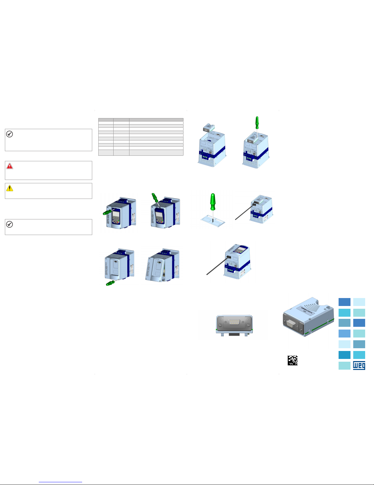
1. Com o controle da so ft-st art er SSW9 00 desen ergizad o, retire a tamp a
frontal (Figura A1 (a) a (d)).
2. Encaixe o aces sório a ser i nstalado em um slot co nforme ind icado na
Figura A1 (e).
3. Fixar o paraf uso de aterramento d o acessório confo rme indicado pela
Figura A1 (f).
4. Remova a tampa do furo d e passage m dos cabo s conforme i ndicado
pela Figura A1 (g) e conecte os cabos de sinal no conector do acessório
(Figura A1 (h)).
5. Recolo que a tampa fronta l (Figura A1 (i)).
6. Energize o controle d a soft-star ter SSW900 e ver ifique se o ac essório foi
identificado corretamente. O modelo do acessório conectado é indicado
em S3.5.1 e S3.5.2.
5 CONFIGURAÇÕES
As conexõe s do acessó rio SSW90 0-CPDP- N devem ser fe itas no
conector conforme Tabe la 1. O c onector do a cessór io é aprese ntado na
Figura A2.
Tabela 1: Sinais d o conector Profibu s DB9 fêmea
Conector Nome Função
1 - 2 - 3 B - Line (+) RxD/TxD positivo (vermelho)
4 RTS Request to send
5 GND 0 V isolado do c ircuito RS485 (saíd a)
6 + 5 V + 5 V iso lado do circuito RS4 85 (saída)
7 - 8 A - Li ne (-) RxD/TxD nega tivo (verde)
9 - Carcaça
metálica
Shield Terra de prote ção
6 OPERAÇÃO
Para detalhes relacionados à programação e operação do produto
utiliza ndo o acess ório SSW9 00-CPDP- N, consul te o manual de
program ação, disponível e m www.weg.net.
Português
APPENDIX A - FIGURES
ANEXO A - FIG URAS
(a) Remova l of the HMI
(a) Remove t he HMI
(a) Remova a H MI
(b) Remova l of the HMI
(b) Remoc ión de la HMI
(b) Remoç ão da HMI
(c) Remove t he screws from t he
front cover
(c) Retir e los tornill os de la tapa
frontal
(c) Retir e os parafuso s da tampa
frontal
(d) Remova l of the front co ver
(d) Remoción de la tapa frontal
(d) Remoç ão da tampa fro ntal
(e) Accessory connection
(e) Conexión del accesorio
(e) Conexã o de acessóri o
(f) Tig hten the scre ws of the
access ory (Torque: 0 .51 N/m)
(f) Apr iete los torn illos del
acceso rio (Torque: 0. 51 N/m)
(f) Ape rte os paraf usos do
acessó rio (Torque: 0. 51 N/m)
(g) Remove t he cover hole
(g) Remue va la tapa del agu jero
(g) Remova a t ampa do furo
(h) Connect the signal cables
(h) cone cte los cable s de señal
(h) Cone cte os cabos de s inal
(i) Accessory connection
(i) Conexión del accesorio
(i) Conexão do acessório
Figure A1: (a) to (i): Installati on of accessory
Figura A1: (a) a (i): Instalaci ón de accesorio
Figura A1: (a) a (i): Instalação d e acessório
Figure A2: Connector location
Figura A2: Localización del conectador
Figura A2: Localização do conector
1 SAFETY INFORMATION
1.1 SAFETY WARNINGS
NOTE!
Only use the Anybus-CC Profibus DP communication plug-in
module (SSW900-CPDP-N) on WEG SSW900 series softstarters.
It is recommended r eading the SSW90 0 user’s manual before
installing or operating this accessory.
1.2 PRELIMINARY RECOMMENDATIONS
DANGER!
Always disconnect the general power supply before connecting
or disconnecting the accessories of the SSW900 soft-starter.
Wait for at least 3 minute s for the full di scharge of th e soft-star ter.
ATTENTION!
Electronic boards have components sensitive to electrostatic
discharges. Do not touch directly on components or connectors.
2 GENERAL INFORMATION
This guide provides directions for the installation, configuration and
operatio n of the Anybu s-CC Profi bus DP communication plug-in
module (SSW900-CPDP-N).
NOTE!
The module connected to slot 1 must be different from the one
connected to slot 2. It is not possible to use simultaneously two
identic al modules on slots 1 a nd 2.
3 PACKAGE CONTENT
Upon receiving the product, check if the package contains:
Accessory in ant i-static package.
Installation, configuration and operation guide.
4 INSTALLATION OF THE ACCESSORY
The SSW90 0-CPDP-N is easil y connected to the SSW9 00 soft-starter by
means of the p lug-and -play conc ept. The pro cedures b elow must be
observed for the proper installation and start-up:
1. With the S SW900 soft-star ter control powere d down, remove the fron t
cover (Figure A1 (a) to (d)).
2. Fi t the accessor y to be installed into a s lot, as shown in Figure A1 (e).
3. Faste n the grounding s crew of the access ory, as shown in Figure A1 (f).
4. Remove the c over of the ca ble passa ge hole, as in dicated in
Figure A1 (g), and connect the signal cables to the connector of
the acces sory (Figure A1 (h)).
5. Put the fro nt cover back in plac e (Figure A1 (i)).
6. Power up the SSW900 sof t-starter c ontrol, and ch eck that the ac cessory
was corre ctly iden tified. Th e model of th e accesso ry conn ected is
indicate d in S3.5.1 and S3.5.2.
5 CONFIGURATIONS
The connections of the SSW900-CPDP-N accessory must be made as
indicated in Table 1. The accesso ry connector is s hown in Figure A2.
Table 1: Signals of th e female DB9 Profi bus connector
Connector Name Function
1 - 2 - 3 B - Line (+) RxD/TxD posi tive (red)
4 RTS Request to send
5 GND 0 V isolated fr om the RS485 circui t (input)
6 + 5 V + 5 V iso lated from the RS485 c ircuit (input)
7 - 8 A - Li ne (-) RxD/TxD negative (green)
9 - -
Metal frame Shield Protective earth
6 OPERATION
For detail s related to the progra mming and operati on of the product usi ng
the SSW90 0-CPDP-N a ccessor y, refer to the pro grammin g manual,
available on www.weg.net.
1 INFORMACIONES DE SEGURIDAD
1.1 AVIS OS DE SEGURIDAD
¡NOTA!
Solamente utilice el módulo plug-in de comunicación Anybus-CC
Profibus D P (SSW900-C PDP-N) en los arr ancadores s uave WEG
serie SSW900.
Se recomienda la le ctura del manual d el usuario del SSW9 00
antes de ins talar o operar es te accesorio.
1.2 PRELIMINARY RECOMMENDATIONS
¡PELIGRO!
Siempre desconecte la alimentación general antes de conectar
o descone ctar los acceso rios del arranc ador suave SSW900.
Aguarde por lo meno s 3 minutos para garantizar la
desenergización completa del arrancador suave.
¡ATENCIÓN!
Las tarjetas electrónicas poseen componentes sensibles
a descarg a electro stática. N o toque direc tamente lo s
componentes o conectores.
2 INFORMACIONES GENERALES
Esta guía orienta en la instalación, configuración y operación del módulo
plug-in de comunicación Anybus-CC Profibus DP (SSW900-CPDP-N).
¡NOTA!
El módulo conecta do en el slot 1 d ebe ser dif erente del
conectado en el slot 2. No es posible utilizar simultáneamente
dos módul os idénticos en lo s slots 1 y 2.
3 CONTENIDO DEL EMBALAJE
Al recibir el producto, verificar si el embalaje contiene:
Accesorio en embalaje antiestático.
Guía de instalación, configuración y operación.
4 INSTALACIÓN DEL ACCESORIO
El acceso rio SSW90 0-CPDP-N e s fácilme nte conect ado al arrancador
suave SSW900 util izando el c oncepto “plu g-and-pl ay”. Los procedim ientos
de abajo de be ser seg uidos para l a correc ta instala ción y pues ta en
funcionamiento:
1. Con el c ontrol del a rrancad or suave SSW9 00 dese nergizad o, retire la
tapa front al (Figura A1 (a) a (d)).
2. Enca je el accesorio a s er instalado en un s lot, conforme es in dicado en la
Figura A1 (e).
3. F ijar el tornill o de puesta a tier ra del acceso rio, conforme e s indicado en
la Figura A1 (f).
4. Remueva la t apa del agu jero de pas aje de los ca bles, con forme es
indicad o en la Figura A1 (g) y conecte los cables de señal en el conector
del acce sorio (Figura A1 (h)).
5. Recolo que a tapa frontal ( Figura A1 (i)).
6. En ergice el c ontrol del a rrancad or suave SSW9 00 y verif ique si el
accesor io fue ide ntifica do correc tamente. El m odelo del a ccesor io
conectado es indicado en S3.5.1 y S3.5.2.
5 CONFIGURACIONES
Las conex iones del accesor io SSW900-CPDP-N d eben ser hechas en e l
conector conforme la Tabla 1. El conector del acc esorio es prese ntado en
la Figura A2.
Tabla 1: Señales d el conector Profi bus DB9 hembra
Conector Nombre Función
1 - 2 - 3 B - Line (+) RxD/TxD positivo (rojo)
4 RTS Request to send
5 GND 0 V aislado de l circuito RS485 (sa lida)
6 + 5 V + 5 V ais lado del circuito RS 485 (salida)
7 - 8 A - Li ne (-) RxD/TxD nega tivo (verde)
9 - Carcasa
metálica
Shield Tierra de protección
6 OPERACIÓN
Para detalles relacionados a la programación y operación del producto
utiliza ndo, el acce sorio SSW9 00-CPD P-N, consul te el manua l de
programación, disponible en www.weg.net.
English
Español
 Loading...