

WEG SSW900-CDN-N Installation, Configuration And Operations Manual
Motors | Autom ation | Energy | Transmi ssion & Distribu tion | Coatings
Anybus-CC DeviceNet Communication
Plug-in Module
Módulo Plug-in de Comunicación
Anybus-CC DeviceNet
Módulo Plug-in de Comunicação
Anybus-CC DeviceNet
SSW900-CDN-N
Installation, Configuration and Operation Guide
Guía de Instalación, Configuración y Operación
Guia de Instalação, Configuração e Operação
Document: 10003988491 / 00
13473675
APPENDIX A - FIGURES
ANEXO A - FIG URAS
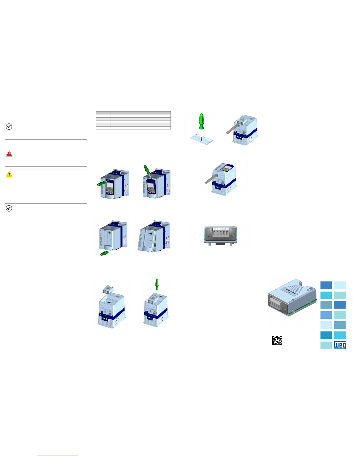
(a) Remova l of the HMI
(a) Remove t he HMI
(a) Remova a H MI
(b) Remova l of the HMI
(b) Remoc ión de la HMI
(b) Remoç ão da HMI
(c) Remove t he screws from t he
front cover
(c) Retir e los tornill os de la tapa
frontal
(c) Retir e os parafuso s da tampa
frontal
(d) Remova l of the front co ver
(d) Remoción de la tapa frontal
(d) Remoç ão da tampa fro ntal
(e) Accessory connection
(e) Conexión del accesorio
(e) Conexã o de acessóri o
(f) Tig hten the scre ws of the
access ory (Torque: 0 .51 N/m)
(f) Apr iete los torn illos del
acceso rio (Torque: 0. 51 N/m)
(f) Ape rte os paraf usos do
acessó rio (Torque: 0. 51 N/m)
1 INFORMAÇÕES DE SEGURANÇA
1.1 AVISOS DE SEGURANÇA
NOTA !
Somente utilizar o módulo plug-in de comunicação Anybus-CC
DeviceN et (SSW900 -CDN-N ) nas soft-st arters WE G série SSW9 00.
Recomenda-se a le itura do ma nual do usu ário da SS W900
antes de ins talar ou operar e sse acessório.
1.2 RECOMENDAÇÕES PRELIMINARES
PERIGO!
Sempre desconec te a alimentaçã o geral antes de co nectar ou
descone ctar os acessór ios da soft-star ter SSW900.
Aguarde pelo menos 3 m inutos para ga rantir a dese nergizaçã o
completa da soft-starter.
ATENÇÃO!
Os cartões eletrônicos possuem componentes sensíveis a
descarg as eletro státicas . Não toque di retamen te sobre os
componentes ou conectores.
2 INFORMAÇÕES GERAIS
Este guia or ienta na in stalaçã o, configur ação e ope ração do mó dulo
plug-in de comunicação Anybus-CC DeviceNet (SSW900-CDN-N).
NOTA !
O módulo conectado no slot 1 deve ser diferente do conectado
no slot 2. Não é possível utilizar simultaneamente dois módulos
idêntic os nos slots 1 e 2.
3 CONTEÚDO DA EMBALAGEM
Ao recebe r o produto, verifica r se a embalagem con tém:
Acessório em emba lagem anti-est ática.
Guia de instalação, configuração e operação.
4 INSTALAÇÃO DO ACESSÓRIO
O acessório SSW900-CDN-N é incorporado de forma simples e rápida à
soft-starter SSW900, usando o co nceito "plu g and play". Os proc edimento s
abaixo deve m ser seg uidos par a a correta i nstalaç ão e coloca ção em
funcionamento:
1. Com o controle da so ft-st ar ter SSW 900 dese nergiz ado, retire a ta mpa
frontal (Figura A1 (a) a (d)).
2. Encaixe o aces sório a se r instala do em um slot c onforme i ndicado n a
Figura A1(e).
3. Fixar o paraf uso de aterramento d o acessório confo rme indicado pela
Figura A1 (f).
4. Remova a tampa do furo d e passag em dos cab os confor me indica do
pela Figura A1 (g) e conecte os cabos de sinal no conector do acessório
(Figura A1 (h)).
5. Recolo que a tampa fronta l (Figura A1 (i)).
6. Energize o c ontrole da sof t-starter SSW 900 e verifi que se o acess ório foi
identificado corretamente. O modelo do acessório conectado é indicado
em S3.5.1 e S3.5.2.
5 CONFIGURAÇÕES
As conexões do acessório SSW900-CDN-N devem ser feitas no conector
conforme Tabe la 1. O cone ctor do acessóri o é apresentado na Figura A2.
Português
Tabela 1: Sinais do conector DeviceNet
Conector
Nome
Descrição
1 V - Pólo negati vo da fonte de aliment ação
2 CAN_L Sinal de comunicação CAN_L
3 Shield Bli ndagem do cabo
4 CAN_H Sinal de comunicação CAN_H
5 V + Pólo positi vo da fonte de aliment ação
6 OPERAÇÃO
Para detalhes relacionados à programação e operação do produto
utiliza ndo o acess ório SSW9 00-CD N-N, cons ulte o manu al de
program ação, disponível e m www.weg.net.
(g) Remove t he cover hole
(g) Remue va la tapa del agu jero
(g) Remova a t ampa do furo
(h) Connect the signal cables
(h) cone cte los cable s de señal
(h) Cone cte os cabos de s inal
(i) Accessory connection
(i) Conexión del accesorio
(i) Conexão do acessório
Figure A1: (a) to (i): Installati on of accessory
Figura A1: (a) a (i): Instalaci ón de accesorio
Figura A1: (a) a (i): Instalação d e acessório
Figure A2: Connector location
Figura A2: Localización del conectador
Figura A2: Localização do conector
1 SAFETY INFORMATION
1.1 SAFETY WARNINGS
NOTE!
Only use the Anybus-CC DeviceNet communication plug-in
module (SSW900-CDN-N) on WEG SSW900 series softstarters.
It is recommended re ading the SSW900 u ser’s manual before
installing or operating this accessory.
1.2 PRELIMINARY RECOMMENDATIONS
DANGER!
Always disconnect the general power supply before connecting
or disconnecting the accessories of the SSW900 soft-starter.
Wait for at le ast 3 minutes fo r the full dis charge of the sof t-starter.
ATTENTION!
Electronic boards have components sensitive to electrostatic
discharges. Do not touch directly on components or connectors.
2 GENERAL INFORMATION
This guide provides directions for the installation, configuration and
operatio n of the Anyb us-CC Dev iceNet communication plug-in
module (SSW900-CDN-N).
NOTE!
The module connected to slot 1 must be different from the one
connected to slot 2. It is not possible to use simultaneously two
identic al modules on slots 1 a nd 2.
3 PACKAGE CONTENT
Upon receiving the product, check if the package contains:
Accessory in anti -static package.
Installation, configuration and operation guide.
4 INSTALLATION OF THE ACCESSORY
The SSW900-CDN-N is easily connected to the SSW900 soft-starter by
means of the p lug-and -play con cept. The pr ocedure s below mu st be
observed for the proper installation and start-up:
1. With t he SSW900 soft-sta rter control powe red down, remove the fr ont
cover (Figure A1 (a) to (d)).
2. Fi t the accessor y to be installed into a s lot, as shown in Figure A1 (e).
3. Faste n the grounding s crew of the access ory, as shown in Figure A1 (f).
4. Remove the c over of the ca ble pass age hole, as i ndicate d in
Figure A1 (g), and connect the signal cables to the connector of
the acces sory (Figure A1 (h)).
5. Put the fro nt cover back in plac e (Figure A1 (i)).
6. Power up the S SW900 soft-s tarter con trol, and chec k that the acce ssory
was corre ctly iden tified. T he model o f the acces sory co nnected i s
indicate d in S3.5.1 and S3.5.2.
5 CONFIGURATIONS
The connections of the SSW900-CDN-N accessory must be made as
indicated in Table 1. The accesso ry connector is s hown in Figure A2.
Table 1: Signals of the DeviceNet connector
Connector
Name
Description
1 V - Negative p ole of the power suppl y
2 CAN_L Communication signal CAN_L
3 Shield Cable shield
4 CAN_H Communication signal CAN_H
5 V + Positive pole of the power supply
6 OPERATION
For detail s related to the progra mming and operati on of the product usi ng
the SSW90 0-CDN- N access ory, refer to the p rogramm ing manu al,
available on www.weg.net.
1 INFORMACIONES DE SEGURIDAD
1.1 AVIS OS DE SEGURIDAD
¡NO TA!
Solamente utilice el módulo plug-in de comunicación Anybus-CC
DeviceN et (SSW90 0-CDN- N) en los ar rancado res suave WEG
serie SSW900.
Se recomienda la le ctura del manual de l usuario del SSW9 00
antes de ins talar o operar es te accesorio.
1.2 PRELIMINARY RECOMMENDATIONS
¡PELIGRO!
Siempre desconecte la alimentación general antes de conectar
o descone ctar los acceso rios del arranc ador suave SSW900.
Aguarde por lo menos 3 m inutos para garantizar la
desenergización completa del arrancador suave.
¡ATENCIÓN!
Las tarjetas electrónicas poseen componentes sensibles
a descarg a electro stática. N o toque dire ctamen te los
componentes o conectores.
2 INFORMACIONES GENERALES
Esta guía orienta en la instalación, configuración y operación del módulo
plug-in de comunicación Anybus-CC DeviceNet (SSW900-CDN-N).
¡NO TA!
El módulo conectad o en el slot 1 d ebe ser dif erente de l
conectado en el slot 2. No es posible utilizar simultáneamente
dos módul os idénticos en lo s slots 1 y 2.
3 CONTENIDO DEL EMBALAJE
Al recibir el producto, verificar si el embalaje contiene:
Accesorio en embalaje antiestático.
Guía de instalación, configuración y operación.
4 INSTALACIÓN DEL ACCESORIO
El accesorio SSW900-CDN-N es fácilmente conectado al arrancador
suave SSW900 util izando el c oncepto “plu g-and-pl ay”. Los procedim ientos
de abajo de be ser seg uidos pa ra la corre cta insta lación y pu esta en
funcionamiento:
1. Con el c ontrol de l arranc ador suave S SW900 de senergi zado, retir e la
tapa front al (Figura A1 (a) a (d)).
2. Enca je el accesorio a s er instalado en u n slot, conforme e s indicado en
la Figura A1 (e).
3. F ijar el tornill o de puesta a tier ra del acceso rio, conforme e s indicado en
la Figura A1 (f).
4. Remueva la t apa del ag ujero de pa saje de lo s cables, c onforme e s
indicad o en la Figura A1 (g) y conecte los cables de señal en el conector
del acce sorio (Figura A1 (h)).
5. Recolo que a tapa frontal ( Figura A1 (i)).
6. En ergice el c ontrol de l arranc ador suave SS W900 y ver ifique s i el
accesor io fue ide ntific ado corre ctamen te. El modelo d el acces orio
conectado es indicado en S3.5.1 y S3.5.2.
5 CONFIGURACIONES
Las conex iones de l acceso rio SSW90 0-CDN -N deben s er hecha s en el
conector conforme la Tabla 1. El conector del acc esorio es prese ntado en
la Figura A2.
English
Español
Tabla 1: Señales del conector DeviceNet
Connector
Nombre
Descripción
1 V - Polo negati vo de la fuente de la ali mentación
2 CAN_L Señal de comunicación CAN_L
3 Shield Blindaje del cable
4 CAN_H Señal de comunicación CAN_H
5 V + Polo positi vo de la fuente de la ali mentación
6 OPERACIÓN
Para detalles relacionados a la programación y operación del producto
utiliza ndo, el acce sorio SSW 900-C DN-N, con sulte el ma nual de
programación, disponible en www.weg.net.
 Loading...