

WEG SSW900-CAN-W User Manual

CANopen
SSW900-CAN-W
Motors | Automation | Energy | Transmission & Distribution | Coatings
User’s Guide

CANopen User’s Guide
Series: SSW900
Software version: 1.2X
Language: English
Document: 10006223748 / 00
Build 5251
Publication Date: 01/2019

The information below describes the reviews made in this manual.
Version Revision Description
V1.2X R00 First edition
Summary of Revisions

Contents
CONTENTS
ABOUT THE MANUAL . . . . . .. . . . . . . . .. . . . . . . . .. . . . . . . . .. . . . . . . . .. . . . . . . . .. . . . . . . . .. . . . . . . . .. . . . . . . . .. . . . . . . 6
ABBREVIATIONS AND DEFINITIONS . . .. . . . . . . . .. . . . . . . . .. . . . . . . . .. . . . . . . . .. . . . . . . . .. . . . . . . . .. . . . . . . . .. . . . . . . . 6
NUMERICAL REPRESENTATION . . . . .. . . . . . . . .. . . . . . . . .. . . . . . . . .. . . . . . . . .. . . . . . . . .. . . . . . . . .. . . . . . . . .. . . . . . . . .. . 6
DOCUMENTS . . . . . . . . . . . . . . . .. . . . . . . . .. . . . . . . . .. . . . . . . . .. . . . . . . . .. . . . . . . . .. . . . . . . . .. . . . . . . . .. . . . . . . . .. . . . . . . . .. . . . . 6
1 MAIN CHARACTERISTICS . . . . .. . . . . . . . .. . . . . . . . .. . . . . . . . .. . . . . . . . .. . . . . . . . .. . . . . . . . .. . . . . . . . .. . . . . . 7
2 INTERFACE DESCRIPTION. . . . . . .. . . . . . . . .. . . . . . . . . . . . . . . . .. . . . . . . . .. . . . . . . . .. . . . . . . . .. . . . . . . . .. . . . 8
2.1 CANOPEN ACCESSORY . . . . . .. . . . . . . . .. . . . . . . . .. . . . . . . . .. . . . . . . . .. . . . . . . . .. . . . . . . . .. . . . . . . . .. . . . . . . . .. . . . . 8
2.2 CONNECTOR . . . .. . . . . . . . .. . . . . . . . .. . . . . . . . .. . . . . . . . .. . . . . . . . .. . . . . . . . .. . . . . . . . .. . . . . . . . .. . . . . . . . .. . . . . . . . .. . 8
2.3 POWER SUPLLY.. . . . . . . . .. . . . . . . . .. . . . . . . . .. . . . . . . . .. . . . . . . . .. . . . . . . . .. . . . . . . . .. . . . . . . . .. . . . . . . . .. . . . . . . . .. . 9
2.4 INDICATION LED . . .. . . . . . . . .. . . . . . . . .. . . . . . . . .. . . . . . . . .. . . . . . . . .. . . . . . . . .. . . . . . . . .. . . . . . . . .. . . . . . . . .. . . . . . . . 9
3 CANOPEN NETWORK INSTALLATION . . . . . . . .. . . . . . . . .. . . . . . . . .. . . . . . . . .. . . . . . . . .. . . . . . . . .. 10
3.1 BAUD RATE . . . . . . . . . . . . . . . . .. . . . . . . . .. . . . . . . . .. . . . . . . . .. . . . . . . . .. . . . . . . . .. . . . . . . . .. . . . . . . . .. . . . . . . . .. . . . . . . . . 10
3.2 ADDRESS IN THE CANOPEN NETWORK .. . . . . . . . . . . . . . . . .. . . . . . . . .. . . . . . . . .. . . . . . . . .. . . . . . . . .. . . . . . . . . 10
3.3 TERMINATION RESISTOR . . . . . . . .. . . . . . . . .. . . . . . . . .. . . . . . . . .. . . . . . . . .. . . . . . . . .. . . . . . . . .. . . . . . . . .. . . . . . . . .. 10
3.4 CABLE . . . . .. . . . . . . . .. . . . . . . . .. . . . . . . . .. . . . . . . . .. . . . . . . . .. . . . . . . . .. . . . . . . . .. . . . . . . . .. . . . . . . . .. . . . . . . . .. . . . . . . . . 10
3.5 CONNECTION IN THE NETWORK . . .. . . . . . . . .. . . . . . . . .. . . . . . . . .. . . . . . . . .. . . . . . . . .. . . . . . . . .. . . . . . . . .. . . . . . 11
4 S STATUS. . . . . . . .. . . . . . . . .. . . . . . . . .. . . . . . . . .. . . . . . . . .. . . . . . . . .. . . . . . . . .. . . . . . . . .. . . . . . . . .. . . . . . . . .. . . . . . . . .. . . . 12
S5 COMMUNICATIONS . . . .. . . . . . . . .. . . . . . . . .. . . . . . . . .. . . . . . . . .. . . . . . . . .. . . . . . . . .. . . . . . . . .. . . . . . . . .. . . . . . . . .. . . . . 12
S5.1 Status Word . . . . . . .. . . . . . . . .. . . . . . . . .. . . . . . . . .. . . . . . . . .. . . . . . . . .. . . . . . . . .. . . . . . . . .. . . . . . . . .. . . . . . . . .. . . . 12
S5.2 Command Word . .. . . . . . . . .. . . . . . . . .. . . . . . . . .. . . . . . . . .. . . . . . . . .. . . . . . . . .. . . . . . . . .. . . . . . . . .. . . . . . . . .. . . . 12
S5.3 Value for Outputs .. . . . . . . . .. . . . . . . . .. . . . . . . . .. . . . . . . . .. . . . . . . . .. . . . . . . . .. . . . . . . . .. . . . . . . . .. . . . . . . . .. . . 13
S5.3.2 Value for AO . . . . .. . . . . . . . .. . . . . . . . .. . . . . . . . .. . . . . . . . .. . . . . . . . .. . . . . . . . .. . . . . . . . .. . . . . . . . .. . . . 13
S5.7 CANopen/DeviceNet .. . . . . . . . .. . . . . . . . .. . . . . . . . .. . . . . . . . .. . . . . . . . .. . . . . . . . .. . . . . . . . .. . . . . . . . .. . . . . . . . 14
5 C CONFIGURATIONS . . . . . .. . . . . . . . .. . . . . . . . .. . . . . . . . .. . . . . . . . .. . . . . . . . .. . . . . . . . .. . . . . . . . .. . . . . . . . .. . . . 16
C8 COMMUNICATION. . .. . . . . . . . .. . . . . . . . .. . . . . . . . .. . . . . . . . .. . . . . . . . .. . . . . . . . .. . . . . . . . .. . . . . . . . .. . . . . . . . .. . . . . . . . 16
C8.4 CANopen/DeviceNet . . . . . . .. . . . . . . . .. . . . . . . . .. . . . . . . . .. . . . . . . . .. . . . . . . . .. . . . . . . . .. . . . . . . . .. . . . . . . . .. . 16
C8.4.5 CAN Error . . . . . . .. . . . . . . . .. . . . . . . . .. . . . . . . . .. . . . . . . . .. . . . . . . . .. . . . . . . . .. . . . . . . . .. . . . . . . . .. . . . . 18
6 OPERATION IN THE CANOPEN NETWORK . . . . . . . . .. . . . . . . . .. . . . . . . . .. . . . . . . . .. . . . . . . . .. 19
6.1 ACCESS TO THE DATA . . . . .. . . . . . . . .. . . . . . . . .. . . . . . . . .. . . . . . . . .. . . . . . . . .. . . . . . . . .. . . . . . . . .. . . . . . . . .. . . . . . . . 19
6.2 CYCLIC DATA.. . . . . . . . .. . . . . . . . .. . . . . . . . .. . . . . . . . .. . . . . . . . .. . . . . . . . .. . . . . . . . .. . . . . . . . .. . . . . . . . .. . . . . . . . .. . . . . 19
6.3 ACYCLIC DATA . . . . . . . .. . . . . . . . .. . . . . . . . .. . . . . . . . .. . . . . . . . .. . . . . . . . .. . . . . . . . .. . . . . . . . .. . . . . . . . .. . . . . . . . .. . . . . 19
6.4 COMMUNICATION OBJECTS - COB . .. . . . . . . . .. . . . . . . . .. . . . . . . . .. . . . . . . . .. . . . . . . . .. . . . . . . . .. . . . . . . . .. . . . 19
6.5 COB-ID . . . . . .. . . . . . . . .. . . . . . . . .. . . . . . . . .. . . . . . . . .. . . . . . . . .. . . . . . . . .. . . . . . . . .. . . . . . . . .. . . . . . . . .. . . . . . . . .. . . . . . . 20
6.6 EDS FILE . . . . . . . .. . . . . . . . .. . . . . . . . .. . . . . . . . .. . . . . . . . .. . . . . . . . .. . . . . . . . .. . . . . . . . .. . . . . . . . .. . . . . . . . .. . . . . . . . .. . . 20
7 OBJECT DICTIONARY. . . .. . . . . . . . .. . . . . . . . .. . . . . . . . .. . . . . . . . .. . . . . . . . .. . . . . . . . .. . . . . . . . .. . . . . . . . .. . . . . 21
7.1 DICTIONARY STRUCTRE . .. . . . . . . . .. . . . . . . . .. . . . . . . . .. . . . . . . . .. . . . . . . . .. . . . . . . . .. . . . . . . . .. . . . . . . . .. . . . . . . . 21
7.2 DATA TYPE . . . . . . . .. . . . . . . . .. . . . . . . . .. . . . . . . . .. . . . . . . . .. . . . . . . . .. . . . . . . . .. . . . . . . . .. . . . . . . . .. . . . . . . . .. . . . . . . . .. 21
7.3 COMMUNICATION PROFILE - COMMUNICATION OBJECTS . . . . . . .. . . . . . . . .. . . . . . . . .. . . . . . . . .. . . . . . 21
7.4 MANUFACTURER SPECIFIC OBJECTS. . . . . . . . .. . . . . . . . .. . . . . . . . .. . . . . . . . .. . . . . . . . .. . . . . . . . .. . . . . . . . .. . . 22
8 COMMUNICATION OBJECTS DESCRIPTION . . . . .. . . . . . . . .. . . . . . . . .. . . . . . . . .. . . . . . . . .. . 23
8.1 IDENTIFICATION OBJECT . . . . . . . .. . . . . . . . .. . . . . . . . .. . . . . . . . .. . . . . . . . .. . . . . . . . .. . . . . . . . .. . . . . . . . .. . . . . . . . .. 23
8.1.1 Object 1000h - Device Type . . . . . . . .. . . . . . . . .. . . . . . . . .. . . . . . . . .. . . . . . . . .. . . . . . . . .. . . . . . . . .. . . . . . . . . 23
8.1.2 Object 1001h - Error Register .. . . . . . . .. . . . . . . . .. . . . . . . . .. . . . . . . . .. . . . . . . . .. . . . . . . . .. . . . . . . . .. . . . . . 23

Contents
8.1.3 Object 1018h - Identity Object . .. . . . . . . . .. . . . . . . . .. . . . . . . . .. . . . . . . . .. . . . . . . . .. . . . . . . . .. . . . . . . . .. . . 24
8.2 SERVICE DATA OBJECTS - SDOS .. . . . . . . .. . . . . . . . .. . . . . . . . .. . . . . . . . .. . . . . . . . .. . . . . . . . .. . . . . . . . .. . . . . . . . . 24
8.2.1 Object 1200h - SDO Server . . . .. . . . . . . . .. . . . . . . . .. . . . . . . . .. . . . . . . . .. . . . . . . . .. . . . . . . . .. . . . . . . . .. . . . . 24
8.2.2 SDOs Operation. . . . . . . . . . . .. . . . . . . . .. . . . . . . . .. . . . . . . . .. . . . . . . . .. . . . . . . . .. . . . . . . . .. . . . . . . . .. . . . . . . . .. 25
8.3 PROCESS DATA OBJECTS - PDOS . . . . . .. . . . . . . . .. . . . . . . . .. . . . . . . . .. . . . . . . . .. . . . . . . . .. . . . . . . . .. . . . . . . . .. 26
8.3.1 PDO Mapping Objects . . . . . . . . . . . . . . .. . . . . . . . .. . . . . . . . .. . . . . . . . .. . . . . . . . .. . . . . . . . .. . . . . . . . .. . . . . . . . 26
8.3.2 Receive PDOs . . . . .. . . . . . . . .. . . . . . . . .. . . . . . . . .. . . . . . . . .. . . . . . . . .. . . . . . . . .. . . . . . . . .. . . . . . . . .. . . . . . . . .. 27
8.3.3 Transmit PDOs . . . . . . . . .. . . . . . . . .. . . . . . . . .. . . . . . . . .. . . . . . . . .. . . . . . . . .. . . . . . . . .. . . . . . . . . . . . . . . . .. . . . . . 28
8.4 SYNCHRONIZATION OBJECT - SYNC .. . . . . . . . .. . . . . . . . .. . . . . . . . . . . . . . . . .. . . . . . . . .. . . . . . . . .. . . . . . . . .. . . . 30
8.5 NETWORK MANAGEMENT - NMT.. . . . . . . . .. . . . . . . . .. . . . . . . . .. . . . . . . . .. . . . . . . . .. . . . . . . . .. . . . . . . . .. . . . . . . . 31
8.5.1 Slave State Control . . .. . . . . . . . .. . . . . . . . .. . . . . . . . .. . . . . . . . .. . . . . . . . .. . . . . . . . .. . . . . . . . .. . . . . . . . .. . . . . . 31
8.5.2 Error Control - Node Guarding. . .. . . . . . . . .. . . . . . . . .. . . . . . . . .. . . . . . . . .. . . . . . . . .. . . . . . . . .. . . . . . . . .. . 32
8.5.3 Error Control - Heartbeat .. . . . . . . . .. . . . . . . . .. . . . . . . . .. . . . . . . . .. . . . . . . . .. . . . . . . . .. . . . . . . . .. . . . . . . . .. 34
8.6 INITIALIZATION PROCEDURE . . . . . . . .. . . . . . . . .. . . . . . . . .. . . . . . . . .. . . . . . . . .. . . . . . . . .. . . . . . . . .. . . . . . . . .. . . . . 35
9 STARTUP GUIDE. . . . . . . . . . . . .. . . . . . . . .. . . . . . . . .. . . . . . . . .. . . . . . . . .. . . . . . . . .. . . . . . . . .. . . . . . . . .. . . . . . . . .. . . . . 37
9.1 INSTALLING THE ACCESSORY . . . . .. . . . . . . . .. . . . . . . . .. . . . . . . . .. . . . . . . . .. . . . . . . . .. . . . . . . . .. . . . . . . . .. . . . . . . 37
9.2 CONFIGURING THE EQUIPMENT . . . . . . . .. . . . . . . . .. . . . . . . . .. . . . . . . . .. . . . . . . . .. . . . . . . . .. . . . . . . . .. . . . . . . . .. 37
9.3 CONFIGURING THE MASTER . . . .. . . . . . . . .. . . . . . . . .. . . . . . . . .. . . . . . . . .. . . . . . . . .. . . . . . . . .. . . . . . . . .. . . . . . . . .. 37
9.4 COMMUNICATION STATUS . . . . . . .. . . . . . . . .. . . . . . . . .. . . . . . . . .. . . . . . . . .. . . . . . . . .. . . . . . . . .. . . . . . . . .. . . . . . . . . 38
9.5 OPERATION USING PROCESS DATA . . . . . .. . . . . . . . .. . . . . . . . .. . . . . . . . .. . . . . . . . .. . . . . . . . .. . . . . . . . .. . . . . . . . 38
9.6 ACCESS TO PARAMETERS – ACYCLIC MESSAGES . . . . . . . .. . . . . . . . .. . . . . . . . .. . . . . . . . .. . . . . . . . .. . . . . . 38
10FAULTS AND ALARMS . . . . . . .. . . . . . . . .. . . . . . . . .. . . . . . . . .. . . . . . . . .. . . . . . . . .. . . . . . . . .. . . . . . . . .. . . . . . . . .. 39
Appendix A .. . . . . . . .. . . . . . . . .. . . . . . . . .. . . . . . . . .. . . . . . . . .. . . . . . . . .. . . . . . . . .. . . . . . . . .. . . . . . . . .. . . . . . . . .. . . . . . . . .. . . 40

ABOUT THE MANUAL
ABOUT THE MANUAL
This manual supplies the necessary information for the operation of the SSW900 soft-starter using the CANopen
protocol. This manual must be used together with the SSW900 user’s manual and programming manual.
ABBREVIATIONS AND DEFINITIONS
ASCII American Standard Code for Information Interchange
CAN Controller Area Network
CiA CAN in Automation
CIP
CRC Cycling Redundancy Check
HMI Human-Machine Interface
ISO International Organization for Standardization
ODVA Open DeviceNet Vendor Association
OSI Open Systems Interconnection
PLC Programmable Logic Controller
ro Read only
rw Read/write
RTR Remote Transmission Request
Common Industrial Protocol
NUMERICAL REPRESENTATION
Decimal numbers are represented by means of digits without suffix. Hexadecimal numbers are represented with the
letter ‘h’ after the number. Binary numbers are represented with the letter ‘b’ after the number.
DOCUMENTS
The CANopen protocol was developed based on the following specifications and documents:
Document Version Source
CAN Specification 2.0 CiA
CiA DS 301 CANopen Application Layer and Communication Profile 4.02 CiA
CiA DRP 303-1 Cabling and Connector Pin Assignment 1.1.1 CiA
CiA DSP 306 Electronic Data Sheet Specification for CANopen 1.1 CiA
CiA DSP 402 Device Profile Drives and Motion Control 2.0 CiA
Planning and Installation Manual - DeviceNet Cable System PUB00027R1 ODVA
SSW900 | 6

MAIN CHARACTERISTICS
1 MAIN CHARACTERISTICS
Below are the main characteristics for communication of the soft-starter SSW900 with CANopen accessory.
Network management task (NMT).
4 transmission PDOs.
4 reception PDOs.
Heartbeat Consumer.
Heartbeat Producer.
Node Guarding.
SDO Client.
SYNC producer/consumer.
It is supplied with an EDS file for the network master configuration.
Acyclic data available for parameterization.
SSW900 | 7
INTERFACE DESCRIPTION
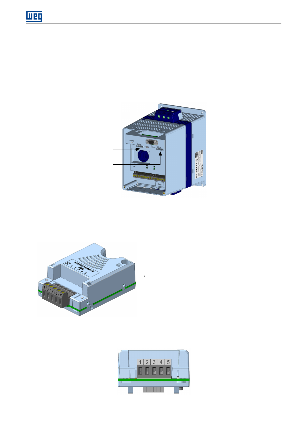
2 INTERFACE DESCRIPTION
The SSW900 soft-starter has two Slots for accessories (Figura 2.1). Parameters S3.5.1 and S3.5.2 present which
accessory was recognized by Slot.
The accessories can be connected to any Slot, but only one type of each communication accessory is allowed.
Read the user’s manual of the SSW900 soft-starter before installing or using this accessory.
Slot 1
Slot 2
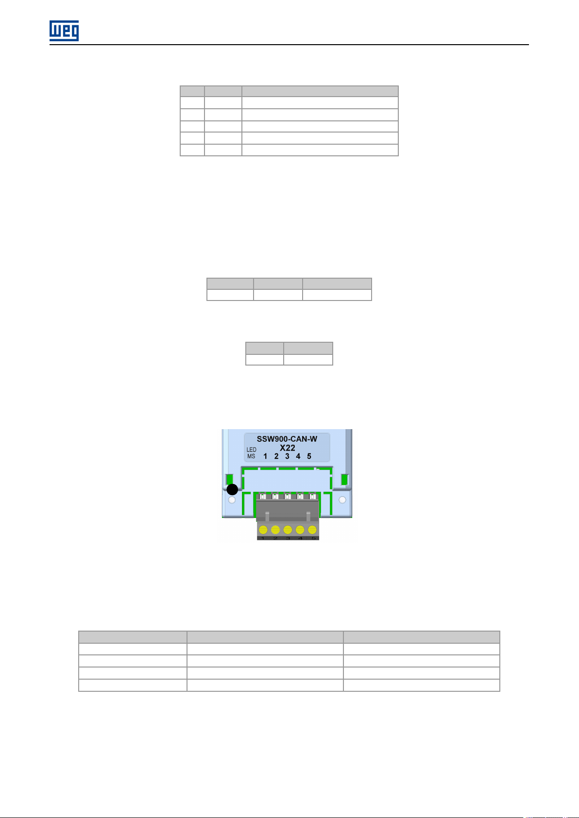
2.1 CANOPEN ACCESSORY
2.2 CONNECTOR
Figure 2.1: Slots for accessories
SSW900-CAN-W:
Supplied items:
– Installation guide.
– CANopen/DeviceNet communication module.
SSW900 | 8
INTERFACE DESCRIPTION
Table 2.1: Pin assignment of connector for CANopen interface
Pin Name Function
1 V- Negative pole of the power supply
2 CAN_L Communication signal CAN_L
3 Shield Cable shield
4 CAN_H Communication signal CAN_H
5 V+ Positive pole of the power supply
2.3 POWER SUPLLY
The power supply of the network must be able to supply enough current to power up the equipments and interfaces
connected to the network. The data for individual consumption and input voltage are presented in tables 2.2 and
2.3.
Table 2.2: Power Suplly (Vdc)
Minimum Maximum Recommended
11 V 30 V 24 V
Table 2.3: Current
Typical Maximum
30 mA 50 mA
2.4 INDICATION LED
MS
The MS LED indicates the conditions of the module itself. That is, whether it is able to work or not. The table below
shows the possible states.
Table 2.4: State of the CANopen module
Status Description Comments
Off No power Green Module operating and in normal conditions Red Module in error Reinitializing the equipment is required.
Flashing green/red Equipment performing self-diagnosis It occurs during initialization.
SSW900 | 9

CANOPEN NETWORK INSTALLATION
3 CANOPEN NETWORK INSTALLATION
The CANopen network, such as several industrial communication networks, for being many times applied in
aggressive environments with high exposure to electromagnetic interference, requires that certain precautions be
taken in order to guarantee a low communication error rate during its operation. Recommendations to perform the
connection of the product in this network are presented next.
NOTE!
✓
3.1 BAUD RATE
Equipments with CANopen interface generally allow the configuration of the desired baud rate, ranging from 10 kbit/s
to 1 Mbit/s. The baud rate that can be used by the equipment depends on the length of the cable used in the
installation. The table 3.1 shows the baud rates and the maximum cable length that can be used in the installation,
according to the protocol recommendation.
Detailed recommendations on how to perform the installation are available at document ”Planning and
Installation Manual” (item DOCUMENTS).
Table 3.1: Supported baud rates and cable length
Baud Rate Cable length
10 kbit/s 1000 m
20 kbit/s 1000 m
50 kbit/s 1000 m
100 kbit/s 600 m
125 kbit/s 500 m
250 kbit/s 250 m
500 kbit/s 100 m
800 kbit/s 50 m
1 Mbit/s 25 m
All network equipment must be programmed to use the same communication baud rate.
3.2 ADDRESS IN THE CANOPEN NETWORK
Each CANopen network device must have an address or Node-ID, and may range from 1 to 127. This address must
be unique for each equipment.
3.3 TERMINATION RESISTOR
The use of termination resistors at the ends of the bus is essential to avoid line reflection, which can impair the signal
and cause communication errors. Termination resistors of 121 Ω | 0.25 W must be connected between the signals
CAN_H and CAN_L at the ends of the main bus.
3.4 CABLE
The connection of CAN_L and CAN_H signals must be done with shielded twisted pair cable. The following table
shows the recommended characteristics for the cable.
SSW900 | 10
CANOPEN NETWORK INSTALLATION
Table 3.2: CANopen cable characteristics
Cable Length (m) Resistence per Meter (mΩ/m) Conductor Cross Section (mm2)
0 ... 40 70 0.25 ... 0.34
40 ... 300 <60 0.34 ... 0.60
300 ... 600 <40 0.50 ... 0.60
600 ... 1000 <26 0.75 ... 0.80
It is necessary to use a twisted pair cable to provide additional 24Vdc power supply to equipments that need this
signal. It is recommended to use a certified DeviceNet cable.
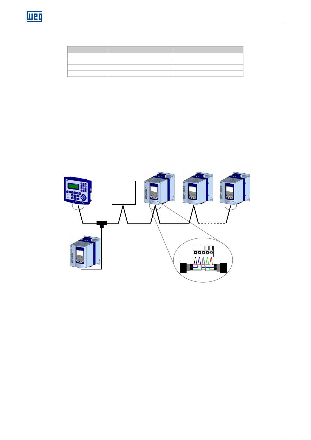
3.5 CONNECTION IN THE NETWORK
In order to interconnect the several network nodes, it is recommended to connect the equipment directly to the
main line without using derivations. During the cable installation the passage near to power cables must be avoided,
because, due to electromagnetic interference, this makes the occurrence of transmission errors possible.
CANopen
Master
24Vdc
Power
Supply
Termination Termination
5
3
1
4
2
Derivation
Figure 3.1: CANopen network installation example
In order to avoid problems with current circulation caused by difference of potential among ground connections, it is
necessary that all the devices be connected to the same ground point.
To avoid voltage difference problems between the power supplies of the network devices, it is recommended that the
network is fed by only one power supply and the signal is provided to all devices through the cable. If it is required
more than one power supply, these should be referenced to the same point. Use the power supply to power the bus
cable system only.
The maximum number of devices connected to a single segment of the network is limited to 64. Repeaters can be
used for connecting a bigger number of devices.
SSW900 | 11

S STATUS
4 S STATUS
Allows viewing of the SSW reading variables.
S5 COMMUNICATIONS
HMI monitoring parameters of the communication interfaces.
For a detailed description, refer to the Anybus-CC, CANopen, DeviceNet and Modbus RTU User’s Manuals of the
SSW according to the interface used.
S5.1 Status Word
.1 SSW 0 ... 15 Bit
Description:
Word of SSW status.
.1 SSW Word of SSW status.
Bit Value/Description
Bit 0
Running
Bit 1
Gener. Enabled
Bit 2
JOG
Bit 3
Initial Test
Bit 4
Ramp Up
Bit 5
Full Voltage
Bit 6
Bypass
Bit 7
Ramp Down
Bit 8
Remote
Bit 9
Braking
Bit 10
FWD/REV
Bit 11
Reverse
Bit 12
Ton
Bit 13
Toff
Bit 14
Alarm
Bit 15
Fault
0: The motor is not enabled.
1: The motor is enabled.
0: When it is general disabled by any mean.
1: When it is general enabled by all the means.
0: The JOG function is inactive.
1: The JOG function is active.
0: None.
1: During the initial tests before the motor starting.
0: It is not accelerating.
1: During the whole acceleration.
0: There is no full voltage applied to the motor.
1: Full voltage is being applied to the motor.
0: With open bypass.
1: With closed bypass.
0: It is not decelerating.
1: During the whole deceleration.
0: Local.
1: Remote.
0: It is not executing braking.
1: During the braking process.
0: It is not reverting the rotation direction.
1: During the rotation reversion process.
0: Forward rotation.
1: Reverse rotation.
0: None.
1: Time before start (C5.7.2).
0: None.
1: Time after stop (C5.7.3).
0: The SSW is not in alarm condition.
1: The SSW is in alarm condition.
Note: The active alarm codes can be read by means of the menu D2.1.
0: The SSW is not in fault condition.
1: The SSW is in fault condition.
Note: The active fault code can be read by means of the menu D1.1.
S5.2 Command Word
.5 Slot1 0 ... 15 Bit
.6 Slot2 0 ... 15 Bit
SSW900 | 12

S STATUS
Description:
Command word of all sources of the SSW. The RUN/STOP and JOG commands of the sources which are not active
will be reset.
.5 Slot1 Control word via any communication accessory connected to Slot 1.
.6 Slot2 Command word via any communication accessory connected to Slot 2.
Bit Value/Description
Bit 0
Start/Stop
Bit 1
Gener. Enabled
Bit 2
JOG
Bit 3
FWD/REV
Bit 4
LOC/REM
Bit 5 … 6
Reserved
Bit 7
Reset
Bit 8 … 15
Reserved
0: stopping by ramp.
1: starting by ramp.
0: general disable.
1: general enable.
0: no JOG.
1: with JOG.
0: clockwise CW.
1: counterclockwise CCW.
0: local.
1: remote.
0 → 1: execute fault reset (if a fault is active).
Note: Only in the 0 to 1 transition command.
NOTE!
✓
If the RUN/STOP and JOG commands are by a certain source and it is active, only these commands
can be viewed in S5.2. For security reasons, all the other commands of the other sources which are
not active will be reset.
S5.3 Value for Outputs
.1 DO Value 0 ... 15 Bit
Description:
Value for digital and analog outputs via serial communication.
.1 DO Value Value for the digital outputs via network interfaces.
Bit Value/Description
Bit 0
DO1
Bit 1
DO2
Bit 2
DO3
Bit 3 … 15
Reserved
0: Inactive.
1: Active.
0: Inactive.
1: Active.
0: Inactive.
1: Active.
S5.3.2 Value for AO
.1 AO in 10 bits 0 ... 1023
Description:
Value for the analog output via network interfaces.
.1 AO in 10 bits Value for the analog output via network interfaces: 0...1023. 0=0% and 1023=100%.
SSW900 | 13

S STATUS
S5.7 CANopen/DeviceNet
.1 CAN Controller Status 0 ... 6
.2 Received Telegram 0 ... 65535
.3 Transmitted Telegram 0 ... 65535
.4 Bus Off Counter 0 ... 65535
.5 Lost Messages 0 ... 65535
.6 CANopen Comm. Status 0 ... 5
.7 CANopen Node State 0 ... 4
Description:
Status of the CAN communication accessory and the protocols that use this interface.
.1 CAN Controller Status It allows identifying if the CAN interface board is properly installed and if the communication
presents errors.
Indication Description
0 = Disabled Inactive CAN interface. It occurs when CAN protocol is not programmed at C8.4.1.
1 = Auto-baud CAN controller is trying to detect baud rate of the network (only for DeviceNet
2 = CAN Enabled CAN interface is active and without errors.
3 = Warning CAN controller has reached the warning state.
4 = Error Passive CAN controller has reached the error passive state.
5 = Bus Off CAN controller has reached the bus off state.
6 = No Bus Power CAN interface does not have power supply between the pins 1 and 5 of the connector.
communication protocol).
.2 Received Telegram This parameter works as a cyclic counter that is incremented every time a CAN telegram is
received. It informs the operator if the device is being able to communicate with the network.
.3 Transmitted Telegram This parameter works as a cyclic counter that is incremented every time a CAN telegram
is transmitted. It informs the operator if the device is being able to communicate with the network.
.4 Bus Off Counter It is a cyclic counter that indicates the number of times the device entered the bus off state in
the CAN network.
.5 Lost Messages It is a cyclic counter that indicates the number of messages received by the CAN interface, but
could not be processed by the device. In case that the number of lost messages is frequently incremented, it is
recommended to reduce the baud rate used in the CAN network.
NOTE!
✓
This counter is reset every time the device is switched off, a reset is performed or the parameter
maximum limit is reached.
.6 CANopen Comm. Status It indicates the board state regarding the CANopen network, informing if the protocol
has been enabled and if the error control service is active (Node Guarding or Heartbeat).
Indication Description
0 = Disabled CANopen protocol disabled.
1 = Reserved
2 = Comm. Enabled Communication enabled.
3 = ErrorCtrl.Enab Communication enabled and error control service enabled (Node Guarding/Heartbeat).
4 = Guarding Error Node Guarding error occurred.
5 = HeartbeatError Heartbeat error occurred.
.7 CANopen Node State It operates as a slave of the CANopen network, and as such element it has a state machine
that controls its behavior regarding the communication. This parameter indicates in which state the device is.
SSW900 | 14

Indication Description
0 = Disabled CANopen protocol disabled.
1 = Initialization Communication with the device is not possible during this stage, which is concluded
automatically.
2 = Stopped Only the NMT object is available.
3 = Operational All the communication objects are available.
4 = PreOperational It is already possible to communicate with the slave but its PDOs are not yet available
for operation.
S STATUS
SSW900 | 15

5 C CONFIGURATIONS
This menu allows the programming of all SSW configuration parameters.
C8 COMMUNICATION
To change information via communication network, the SSW has several standard protocols.
The following necessary accessories and protocols are available:
Protocol Accessory
CANopen SSW900-CAN-W
DeviceNet SSW900-CDN-N, SSW900-CAN-W
EtherNet/IP SSW900-CETH-IP-N
Modbus RTU SSW900-CRS485-W
Modbus TCP SSW900-CMB-TCP-N
Profibus DP SSW900-CPDP-N
PROFINET IO SSW900-CPN-IO-N
C CONFIGURATIONS
For further details regarding the SSW configuration to operate these protocols, refer to the SSW Communication
Manual.
C8.4 CANopen/DeviceNet
Configuration for the SSW900-CAN-W communication accessory and protocols that use this interface.
C8.4 CANopen/DeviceNet
C8.4.1 Protocol
Range: 0 ... 2 Default: 2
Properties:
Description:
It allows selecting the desired protocol for the CAN interface.
Indication Description
0 = Disabled Disable CAN interface.
1 = CANopen Enable CAN interface with CANopen protocol.
2 = DeviceNet Enable CAN interface with DeviceNet protocol.
C8.4 CANopen/DeviceNet
C8.4.2 Address
Range: 0 ... 127 Default: 63
Properties:
SSW900 | 16

C CONFIGURATIONS
Description:
It allows programming the address used for the CAN communication. It is necessary that each element of the network
has an address different from the others. The valid addresses for this parameter depend on the protocol programmed
in P0700:
P0700 = 1 (CANopen): valid addresses: 1 to 127.
P0700 = 2 (DeviceNet): valid addresses: 0 to 63.
NOTE!
✓
C8.4 CANopen/DeviceNet
C8.4.3 Baud Rate
Range: 0 ... 8 Default: 0
Properties:
Description:
It allows programming the desired baud rate for the CAN interface, in bits per second. This rate must be the same
for all the devices connected to the network. The supported bauld rates for the device depend on the protocol
programmed in the parameter C8.4.1:
After changing this configuration, for the modification to be effective, the change takes effect only if the
CAN interface is not exchanging cyclic data with the network.
C8.4.1 = 1 (CANopen): It is possible to use any rate specified in this parameter, but it does not have the automatic
baud rate detection function – autobaud.
C8.4.1 = 2 (DeviceNet): only the 500, 250 and 125 Kbit/s rates are supported. Other options will enable the
automatic baud rate detection function – autobaud.
After a successful detection, the baud rate parameter (C8.4.3) changes automatically to the detected rate. In order
to execute the autobaud function again, it is necessary to change the parameter C8.4.3 to one of the ‘Autobaud’
options.
Indication Description
0 = 1 Mbps/Auto CAN baud rate (automatic detection for DeviceNet).
1 = Reserved Reserved
2 = 500 Kbps CAN baud rate.
3 = 250 Kbps CAN baud rate.
4 = 125 Kbps CAN baud rate.
5 = 100 Kbps/Auto CAN baud rate (automatic detection for DeviceNet).
6 = 50 Kbps/Auto CAN baud rate (automatic detection for DeviceNet).
7 = 20 Kbps/Auto CAN baud rate (automatic detection for DeviceNet).
8 = 10 Kbps/Auto CAN baud rate (automatic detection for DeviceNet).
NOTE!
✓
After changing this configuration, for the modification to be effective, the change takes effect only if the
CAN interface is not exchanging cyclic data with the network.
C8.4 CANopen/DeviceNet
C8.4.4 Bus Off Reset
Range: 0 ... 1 Default: 1
Properties:
Description:
It allows programming the inverter behavior when detecting a bus off error at the CAN interface.
SSW900 | 17

C CONFIGURATIONS
Indication Description
0 = Manual If bus off occurs, the A134/F134 alarm will be indicated on the HMI and the
1 = Automatic If bus off occurs, the communication will be reinitiated automatically and the error will be
communication will be disabled. In case of alarm, the action programmed in parameter
C8.4.5.2 will be executed. In order that the inverter communicates again through the
CAN interface, it will be necessary to disable and enable the interface, or reinitiate the
device.
ignored. In this case the alarm will not be indicated on the HMI and the inverter will not
execute the action programmed in C8.4.5.2.
C8.4.5 CAN Error
Protection against interruption in the CAN communication.
If for some reason there is an interruption in the CAN communication, a communication error will be indicated, alarm
A133...A137 or fault F133...F137 will be shown on the HMI, depending on the programming of C8.4.5.1, and the
action programmed in C8.4.5.2 will be executed.
It only occurs after the equipment is online. This error is only generated for the SSW900-CAN-W module.
C8.4.5 CAN Error
C8.4.5.1 Mode
Range: 0 ... 2 Default: 0
Properties:
Description:
It allows configuring the tripping mode of the protection against interruption in the CAN communication.
Indication Description
0 = Inactive No tripping.
1 = Fault Trips as fault. Disables the motor.
2 = Alarm Trips as alarm. Action described in C8.4.5.2.
C8.4.5 CAN Error
C8.4.5.2 Alarm Action
Range: 0 ... 4 Default: 0
Properties:
Description:
Action for the CAN communication interruption alarm.
The actions described in this parameter are executed through the writing of the respective bits in the control word
of the SLOT to which the accessory SSW900-CAN-W is connected. Thus, for the commands to be effective, the
equipment must be programmed to be controlled by the network interface used. This programming is done through
menu C3.
✓
Indication Description
0 = Indicates Only No action is taken; the equipment remains in the current state.
1 = Ramp Stop The stop by ramp command is executed, and the motor stops according to the
programmed deceleration ramp.
2 = General Disable The equipment is general disabled, and the motor stops by inertia.
3 = Change to LOC The equipment is commanded to local mode.
4 = Change to REM The equipment is commanded to remote mode.
NOTE!
The alarm action will only have a function if the error tripping mode C8.4.5.1 is programmed for Alarm.
SSW900 | 18

OPERATION IN THE CANOPEN NETWORK
6 OPERATION IN THE CANOPEN NETWORK
6.1 ACCESS TO THE DATA
Each slave of the CANopen network has a list called object dictionary that contains all the data accessible via network.
Each object of this list is identified with an index, which is used during the equipment configuration as well as during
message exchanges. This index is used to identify the object being transmitted.
6.2 CYCLIC DATA
Cyclic data is the data normally used for status monitoring and equipment control. For CANopen protocol, the
interface supports 4 receive PDOs and 4 transmit PDOs.
It is necessary the configuration to be made both at the slave and master.
6.3 ACYCLIC DATA
In addition to the cyclic data, the interface also provides acyclic data via SDO. Using this type of communication, you
can access any equipment parameter. Access to this type of data is commonly done using instructions for reading
or writing data, which should indicate the index and sub-index to the desired parameter. The item 7.4 describes how
to address the parameters for SSW900 soft-starter.
6.4 COMMUNICATION OBJECTS - COB
There is a specific set of objects that are responsible for the communication among the network devices. Those
objects are divided according to the type of data and the way they are sent or received by a device. The following
communication objects (COBs) are described by the specification:
Table 6.1: Types of Communication Objects (COBs)
Type of object Description
Service Data Object (SDO) SDO are objects responsible for the direct access to the object dictionary of a device. By means
Process Data Object (PDO) PDO are used for accessing equipment data without the need of indicating explicitly which dictionary
Emergency Object (EMCY) This object is responsible for sending messages to indicate the occurrence of errors in the device.
Syncronization Object (SYNC) In the CANopen network, it is possible to program a device (SYNC producer) to send periodically
Network Management (NMT) Every CANopen network needs a master that controls the other devices (slaves) in the network.
of messages using SDO, it is possible to indicate explicitly (by the object index) what data is being
handled. There are two SDO types: Client SDO, responsible for doing a read or write request to
a network device, and the Server SDO, responsible for taking care of that request. Since SDO are
usually used for the configuration of a network node, they have less priority than other types of
message.
object is being accessed. Therefore, it is necessary to configure previously which data the PDO will
be transmitting (data mapping). There are also two types of PDO: Receive PDO and Transmit PDO.
They are usually utilized for transmission and reception of data used in the device operation, and for
that reason they have higher priority than the SDO.
When an error occurs in a specific device (EMCY producer), it can send a message to the network.
In the case that any network device be monitoring that message (EMCY consumer), it can be
programmed so that an action be taken (disabling the other devices, error reset, etc.).
a synchronization message for all the network devices. Those devices (SYNC consumers) will then
be able, for instance, to send a certain datum that needs to be made available periodically.
This master will be responsible for a set of services that control the slave communications and their
state in the CANopen network. The slaves are responsible for receiving the commands sent by
the master and for executing the requested actions. The protocol describes two types of service:
device control service, with which the master controls the state of each network slave, and error
control service (Node Guarding an Heartbeat), with which the device sends periodic messages to
inform that the connection is active.
SSW900 | 19

OPERATION IN THE CANOPEN NETWORK
All the communication of the slave with the network is performed using those objects, and the data that can be
accessed are the existent in the device object dictionary.
6.5 COB-ID
A telegram of the CANopen network is always transmitted by a communication object (COB). Every COB has an
identifier that indicates the type of data that is being transported. This identifier, called COB-ID has an 11 bit size,
and it is transmitted in the identifier field of a CAN telegram. It can be subdivided in two parts:
Function Code Address
bit 10 bit 9 bit 8 bit 7 bit 6 bit 5 bit 4 bit 3 bit 2 bit 1 bit 0
Function Code: indicates the type of object that is being transmitted.
Adrress: indicates with which network device the telegram is linked.
A table with the standard values for the different communication objects is presented next. Notice that the standard
value of the object depends on the slave address, with the exception of the COB-ID for NMT and SYNC, which are
common for all the network elements. Those values can also be changed during the device configuration stage.
Table 6.2: COB-ID for the different objects
COB Function Code (bits 10-7) COB-ID Resultant COB-ID (function + address)
NMT 0000 0
SYNC 0001 128 (80h)
EMCY 0001 129 - 255 (81h - FFh)
PDO1 (tx) 0011 385 - 511 (181h - 1FFh)
PDO1 (rx) 0100 513 - 639 (201h - 27Fh)
PDO2 (tx) 0101 641 - 767 (281h - 2FFh)
PDO2 (rx) 0110 769 - 895 (301h - 37Fh)
PDO3 (tx) 0111 897 - 1023 (381h - 3FFh)
PDO3 (rx) 1000 1025 - 1151 (401h - 47Fh)
PDO4 (tx) 1001 1153 - 1279 (481h - 4FFh)
PDO4 (rx) 1010 1281 - 1407 (501h - 57Fh)
SDO (tx) 1011 1409 - 1535 (581h - 5FFh)
SDO (rx) 1100 1537 - 1663 (601h - 67Fh)
Node Guarding/Heartbeat 1110 1793 - 1919 (701h - 77Fh)
6.6 EDS FILE
Each device on an CANopen network has an EDS configuration file, which contains information about the device
functions on the network. This file is used by a master or configuration software to program devices present at
CANopen network.
The EDS file is available from WEG website (http://www.weg.net). It is important to note if the EDS configuration file
is compatible with the firmware version of the SSW900 soft-starter.
SSW900 | 20

OBJECT DICTIONARY
7 OBJECT DICTIONARY
The object dictionary is a list containing several equipment data which can be accessed via CANopen network. An
object of this list is identified by means of a 16-bit index, and it is based in that list that all the data exchange between
devices is performed.
The CiA DS 301 document defines a set of minimum objects that every CANopen network slave must have. The
objects available in that list are grouped according to the type of function they execute. The objects are arranged in
the dictionary in the following manner:
Table 7.1: Object dictionary groupings
Index Objects Description
0001h - 025Fh Data type definition Used as reference for the data type supported by the system.
1000h - 1FFFh Communication objects They are objects common to all the CANopen devices. They
2000h – 5FFFh Manufacturer specific objects In this range, each CANopen equipment manufacturer is free to define
6000h – 9FFFh Standardized device objects This range is reserved to objects that describe the behavior of similar
contain general information about the equipment and also data for the
communication configuration.
which data those objects will represent.
equipment, regardless of the manufacturer.
The other indexes that are not referred in this list are reserved for future use.
7.1 DICTIONARY STRUCTRE
The general structure of the dictionary has the following format:
Index Object Name Type Access
Index: indicates directly the object index in the dictionary.
Object: describes which information the index stores (simple variable, array, record, etc.).
Name: contains the name of the object in order to facilitate its identification.
Type: indicates directly the stored data type. For simple variables, this type may be an integer, a float, etc. For
arrays, it indicates the type of data contained in the array. For records, it indicates the record format according
to the types described in the first part of the object dictionary (indexes 0001h – 0360h).
Access: informs if the object in question is accessible only for reading (ro), for reading and writing (rw), or if it is
a constant (const).
For objects of the array or record type, a sub-index that is not described in the dictionary structure is also necessary.
7.2 DATA TYPE
The first part of the object dictionary (index 0001h – 025Fh) describes the data types that can be accessed at a
CANopen network device. They can be basic types, as integers and floats, or compound types formed by a set of
entries, as records and arrays.
7.3 COMMUNICATION PROFILE - COMMUNICATION OBJECTS
The indexes from 1000h to 1FFFh in the object dictionary correspond to the part responsible for the CANopen network
communication configuration. Those objects are common to all the devices, however only a few are obligatory. A list
with the objects of this range that are supported by the soft-starter SSW900 is presented next.
SSW900 | 21

Table 7.2: Object list – Communication Profile
Index Object Name Type Access
1000h VAR device type UNSIGNED32 ro
1001h VAR error register UNSIGNED8 ro
1005h VAR COB-ID SYNC UNSIGNED32 rw
100Ch VAR quard time UNSIGNED16 rw
100Dh VAR life time factor UNSIGNED8 rw
1016h ARRAY consume heartbeat time UNSIGNED32 rw
1017h VAR producer heartbeat time UNSIGNED16 rw
1018h RECORD Identity Object Identity ro
Server SDO Parameter
1200h RECORD 1st Server SDO parameter SDO Parameter ro
Receive PDO Communication Parameter
1400h RECORD 1st receive PDO Parameter PDO CommPar rw
1401h RECORD 2nd receive PDO Parameter PDO CommPar rw
1402h RECORD 3rd receive PDO Parameter PDO CommPar rw
1403h RECORD 4th receive PDO Parameter PDO CommPar rw
Receive PDO Mapping Parameter
1600h RECORD 1st receive PDO mapping PDO Mapping rw
1601h RECORD 2nd receive PDO mapping PDO Mapping rw
1602h RECORD 3rd receive PDO mapping PDO Mapping rw
1603h RECORD 4th receive PDO mapping PDO Mapping rw
Transmit PDO Communication Parameter
1800h RECORD 1st transmit PDO Parameter PDO CommPar rw
1801h RECORD 2nd transmit PDO Parameter PDO CommPar rw
1802h RECORD 3rd transmit PDO Parameter PDO CommPar rw
1803h RECORD 4th transmit PDO Parameter PDO CommPar rw
Transmit PDO Mapping Parameter
1A00h RECORD 1st transmit PDO mapping PDO Mapping rw
1A01h RECORD 2nd transmit PDO mapping PDO Mapping rw
1A02h RECORD 3rd transmit PDO mapping PDO Mapping rw
1A03h RECORD 4th transmit PDO mapping PDO Mapping rw
OBJECT DICTIONARY
These objects can only be read and written via the CANopen network, it is not available via the keypad (HMI) or other
network interface. The network master, in general, is the equipment responsible for setting up the equipment before
starting the operation. The EDS configuration file brings the list of all supported communication objects.
Refer to item 8 for more details on the available objects in this range of the objects dictionary.
7.4 MANUFACTURER SPECIFIC OBJECTS
For indexes from 2000h to 5FFFh, each manufacture is free to define which objects will be present, and also the
type and function of each one. In the case of the SSW900, the whole list of parameters was made available in this
object range. It is possible to operate the SSW900 by means of these parameters, carrying out any function that the
inverter can execute. The parameters were made available starting from the index 2000h, and by adding their Net Id
to this index their position in the dictionary is obtained. To identify how the parameters are distributed in the object
dictionary, refer to the Appendix A.
In order to be able to program the SSW900 operation correctly via the CANopen network, it is necessary to know its
operation through the parameters.
Refer to the SSW900 soft-starter programming manual for a complete list of the parameters and their detailed
description.
SSW900 | 22
 Loading...