

WEG SSW900 User Manual

Motors | Automation | Energy | Transmission & Distribution | Coatings
Anybus Modbus TCP
SSW900
User’s Guide

Anybus Modbus TCP User’s Guide
Series: SSW900
Software version: 1.1X
Language: English
Document Number: 10004628327 / 01
Build 4847
Publication Date: 08/2018

Version Revsion Description
- R00 First edition.
- R01 General revision V1.1x.
Summary of Revisions

Contents
CONTENTS
ABOUT THE MANUAL . . . . . . . . . . . . . . . . . . . . . . . . . . . . . . . . . . . . . . . . . . . . . . . . . . . . . . . . . . . . . . . . . . . . . . . . . . . . . . . . . . . . . 6
ABBREVIATIONS AND DEFINITIONS . . . . . . . . . . . . . . . . . . . . . . . . . . . . . . . . . . . . . . . . . . . . . . . . . . . . . . . . . . . . . . . . . . . . . . . . . . 6
NUMERICAL REPRESENTATION . . . . . . . . . . . . . . . . . . . . . . . . . . . . . . . . . . . . . . . . . . . . . . . . . . . . . . . . . . . . . . . . . . . . . . . . . . . . . . . 6
DOCUMENTS . . . . . . . . . . . . . . . . . . . . . . . . . . . . . . . . . . . . . . . . . . . . . . . . . . . . . . . . . . . . . . . . . . . . . . . . . . . . . . . . . . . . . . . . . . . . . . . . . . . . . . 6
1 MAIN CHARACTERISTICS . . . . . . . . . . . . . . . . . . . . . . . . . . . . . . . . . . . . . . . . . . . . . . . . . . . . . . . . . . . . . . . . . . . . . . . . . . 7
2 INTERFACE DESCRIPTION. . . . . . . . . . . . . . . . . . . . . . . . . . . . . . . . . . . . . . . . . . . . . . . . . . . . . . . . . . . . . . . . . . . . . . . . . 8
2.1 ANYBUS MODBUS TCP ACCESSORY . . . . . . . . . . . . . . . . . . . . . . . . . . . . . . . . . . . . . . . . . . . . . . . . . . . . . . . . . . . . . . . . . . . 8
2.2 CONNECTORS . . . . . . . . . . . . . . . . . . . . . . . . . . . . . . . . . . . . . . . . . . . . . . . . . . . . . . . . . . . . . . . . . . . . . . . . . . . . . . . . . . . . . . . . . . . . . . 8
2.3 INDICATION LEDS . . . . . . . . . . . . . . . . . . . . . . . . . . . . . . . . . . . . . . . . . . . . . . . . . . . . . . . . . . . . . . . . . . . . . . . . . . . . . . . . . . . . . . . . . . 9
3 MODBUS TCP NETWORK INSTALLATION . . . . . . . . . . . . . . . . . . . . . . . . . . . . . . . . . . . . . . . . . . . . . . . . 10
3.1 IP ADDRESS . . . . . . . . . . . . . . . . . . . . . . . . . . . . . . . . . . . . . . . . . . . . . . . . . . . . . . . . . . . . . . . . . . . . . . . . . . . . . . . . . . . . . . . . . . . . . . . . . 10
3.2 COMMUNICATION RATE . . . . . . . . . . . . . . . . . . . . . . . . . . . . . . . . . . . . . . . . . . . . . . . . . . . . . . . . . . . . . . . . . . . . . . . . . . . . . . . . . . 10
3.3 CABLE . . . . . . . . . . . . . . . . . . . . . . . . . . . . . . . . . . . . . . . . . . . . . . . . . . . . . . . . . . . . . . . . . . . . . . . . . . . . . . . . . . . . . . . . . . . . . . . . . . . . . . . . 10
3.4 NETWORK TOPOLOGY . . . . . . . . . . . . . . . . . . . . . . . . . . . . . . . . . . . . . . . . . . . . . . . . . . . . . . . . . . . . . . . . . . . . . . . . . . . . . . . . . . . . 10
3.5 RECOMMENDATIONS FOR GROUNDING CONNECTION AND CABLE ROUTING . . . . . . . . . . . . . . . . 11
4 S STATUS. . . . . . . . . . . . . . . . . . . . . . . . . . . . . . . . . . . . . . . . . . . . . . . . . . . . . . . . . . . . . . . . . . . . . . . . . . . . . . . . . . . . . . . . . . . . . . . . . . . . . . 12
S5 COMMUNICATIONS . . . . . . . . . . . . . . . . . . . . . . . . . . . . . . . . . . . . . . . . . . . . . . . . . . . . . . . . . . . . . . . . . . . . . . . . . . . . . . . . . . . . . . . . . . 12
S5.1 Status Word . . . . . . . . . . . . . . . . . . . . . . . . . . . . . . . . . . . . . . . . . . . . . . . . . . . . . . . . . . . . . . . . . . . . . . . . . . . . . . . . . . . . . . . . . . . . 12
S5.2 Command Word . . . . . . . . . . . . . . . . . . . . . . . . . . . . . . . . . . . . . . . . . . . . . . . . . . . . . . . . . . . . . . . . . . . . . . . . . . . . . . . . . . . . . . . 12
S5.3 Value for Outputs . . . . . . . . . . . . . . . . . . . . . . . . . . . . . . . . . . . . . . . . . . . . . . . . . . . . . . . . . . . . . . . . . . . . . . . . . . . . . . . . . . . . . 13
S5.5 Anybus-CC . . . . . . . . . . . . . . . . . . . . . . . . . . . . . . . . . . . . . . . . . . . . . . . . . . . . . . . . . . . . . . . . . . . . . . . . . . . . . . . . . . . . . . . . . . . . . 14
5 C CONFIGURATIONS . . . . . . . . . . . . . . . . . . . . . . . . . . . . . . . . . . . . . . . . . . . . . . . . . . . . . . . . . . . . . . . . . . . . . . . . . . . . . . . . . . 15
C8 COMMUNICATION. . . . . . . . . . . . . . . . . . . . . . . . . . . . . . . . . . . . . . . . . . . . . . . . . . . . . . . . . . . . . . . . . . . . . . . . . . . . . . . . . . . . . . . . . . . . 15
C8.1 I/O Data . . . . . . . . . . . . . . . . . . . . . . . . . . . . . . . . . . . . . . . . . . . . . . . . . . . . . . . . . . . . . . . . . . . . . . . . . . . . . . . . . . . . . . . . . . . . . . . . 15
C8.1.1 Data Read . . . . . . . . . . . . . . . . . . . . . . . . . . . . . . . . . . . . . . . . . . . . . . . . . . . . . . . . . . . . . . . . . . . . . . . . . . . . . . . . . . . 15
C8.1.2 Data Write . . . . . . . . . . . . . . . . . . . . . . . . . . . . . . . . . . . . . . . . . . . . . . . . . . . . . . . . . . . . . . . . . . . . . . . . . . . . . . . . . . . 16
C8.3 Anybus-CC. . . . . . . . . . . . . . . . . . . . . . . . . . . . . . . . . . . . . . . . . . . . . . . . . . . . . . . . . . . . . . . . . . . . . . . . . . . . . . . . . . . . . . . . . . . . . 18
C8.3.9 Modbus TCP Timeout. . . . . . . . . . . . . . . . . . . . . . . . . . . . . . . . . . . . . . . . . . . . . . . . . . . . . . . . . . . . . . . . . . . . . . 20
6 OPERATION IN THE MODBUS TCP NETWORK – SERVER MODE . . . . . . . . . 22
6.1 AVAILABLE FUNCTIONS . . . . . . . . . . . . . . . . . . . . . . . . . . . . . . . . . . . . . . . . . . . . . . . . . . . . . . . . . . . . . . . . . . . . . . . . . . . . . . . . . . . 22
6.2 MEMORY MAP .. . . . . . . . . . . . . . . . . . . . . . . . . . . . . . . . . . . . . . . . . . . . . . . . . . . . . . . . . . . . . . . . . . . . . . . . . . . . . . . . . . . . . . . . . . . . . 22
6.2.1 Parameters . . . . . . . . . . . . . . . . . . . . . . . . . . . . . . . . . . . . . . . . . . . . . . . . . . . . . . . . . . . . . . . . . . . . . . . . . . . . . . . . . . . . . . . . . . 22
6.2.2 Indirect Parameters . . . . . . . . . . . . . . . . . . . . . . . . . . . . . . . . . . . . . . . . . . . . . . . . . . . . . . . . . . . . . . . . . . . . . . . . . . . . . . . . 23
6.2.3 Input words . . . . . . . . . . . . . . . . . . . . . . . . . . . . . . . . . . . . . . . . . . . . . . . . . . . . . . . . . . . . . . . . . . . . . . . . . . . . . . . . . . . . . . . . . 23
6.2.4 Output Words . . . . . . . . . . . . . . . . . . . . . . . . . . . . . . . . . . . . . . . . . . . . . . . . . . . . . . . . . . . . . . . . . . . . . . . . . . . . . . . . . . . . . . 24
6.3 DATA ACCESS . . . . . . . . . . . . . . . . . . . . . . . . . . . . . . . . . . . . . . . . . . . . . . . . . . . . . . . . . . . . . . . . . . . . . . . . . . . . . . . . . . . . . . . . . . . . . . . 26
6.4 COMMUNICATION ERRORS . . . . . . . . . . . . . . . . . . . . . . . . . . . . . . . . . . . . . . . . . . . . . . . . . . . . . . . . . . . . . . . . . . . . . . . . . . . . . . 26
7 STARTUP GUIDE. . . . . . . . . . . . . . . . . . . . . . . . . . . . . . . . . . . . . . . . . . . . . . . . . . . . . . . . . . . . . . . . . . . . . . . . . . . . . . . . . . . . . . . . . . 27
7.1 INSTALLING THE ACCESSORY . . . . . . . . . . . . . . . . . . . . . . . . . . . . . . . . . . . . . . . . . . . . . . . . . . . . . . . . . . . . . . . . . . . . . . . . . . . 27
7.2 CONFIGURING THE EQUIPMENT . . . . . . . . . . . . . . . . . . . . . . . . . . . . . . . . . . . . . . . . . . . . . . . . . . . . . . . . . . . . . . . . . . . . . . . . 27
7.3 CONFIGURING THE MASTER . . . . . . . . . . . . . . . . . . . . . . . . . . . . . . . . . . . . . . . . . . . . . . . . . . . . . . . . . . . . . . . . . . . . . . . . . . . . . 27
7.4 COMMUNICATION STATUS . . . . . . . . . . . . . . . . . . . . . . . . . . . . . . . . . . . . . . . . . . . . . . . . . . . . . . . . . . . . . . . . . . . . . . . . . . . . . . . 28
8 WEB SERVER . . . . . . . . . . . . . . . . . . . . . . . . . . . . . . . . . . . . . . . . . . . . . . . . . . . . . . . . . . . . . . . . . . . . . . . . . . . . . . . . . . . . . . . . . . . . . . . 29

Contents
9 FAULTS AND ALARMS . . . . . . . . . . . . . . . . . . . . . . . . . . . . . . . . . . . . . . . . . . . . . . . . . . . . . . . . . . . . . . . . . . . . . . . . . . . . . . . . 30
Appendix A .. . . . . . . . . . . . . . . . . . . . . . . . . . . . . . . . . . . . . . . . . . . . . . . . . . . . . . . . . . . . . . . . . . . . . . . . . . . . . . . . . . . . . . . . . . . . . . . . . . . . . 31

ABOUT THE MANUAL
ABOUT THE MANUAL
This manual supplies the necessary information for the operation of the SSW900 soft-starter using the Anybus
Modbus TCP interface. This manual must be used together with the SSW900 user’s manual and programming
manual.
ABBREVIATIONS AND DEFINITIONS
ASCII American Standard Code for Information Interchange
CRC Cycling Redundancy Check
CSMA/CD Carrier Sense Multiple Access/Collision Detection
IP Internet Protocol
MAC Medium Access Control
TCP Transmission Control Protocol
UDP User Datagram Protocol
LSB Least Significant Bit/Byte
MSB Most Significant Bit/Byte
ro Read only
rw Read/write
NUMERICAL REPRESENTATION
Decimal numbers are represented by means of digits without suffix. Hexadecimal numbers are represented with the
letter ’h’ after the number. Binary numbers are represented with the letter ’b’ after the number.
DOCUMENTS
The Modbus protocol was developed based on the following specifications and documents:
Document Version Source
MODBUS Application Protocol Specification, December 28th 2006. V1.1b MODBUS.ORG
MODBUS Messaging On TCP/IP Implementation Guide, October 24th 2006. V1.0b MODBUS.ORG
In order to obtain this documentation, consult MODBUS.ORG, which is nowadays the organization that keeps, publishes and updates the information related to the Modbus protocol.
SSW900 | 6

MAIN CHARACTERISTICS
1 MAIN CHARACTERISTICS
Below are the main characteristics for communication of the soft-starter SSW900 with Anybus Modbus TCP accessory.
The interface follows the Fast Ethernet 100BASE-TX standard.
It allows communication using the 10 or 100 Mbps rates in half or full duplex mode.
It has a built-in, two-port Ethernet switch.
The Ethernet ports work with Auto-MDIX (automatic medium-dependent interface crossover), a technology which
automatically detects the type of cable used and configures the connection accordingly, eliminating the need of
cross-over cables.
Operates as Modbus TCP server.
The server provides up to 4 simultaneous Modbus TCP connections.
Allows data communication for equipment operation and parameterization.
SSW900 | 7
INTERFACE DESCRIPTION
2 INTERFACE DESCRIPTION
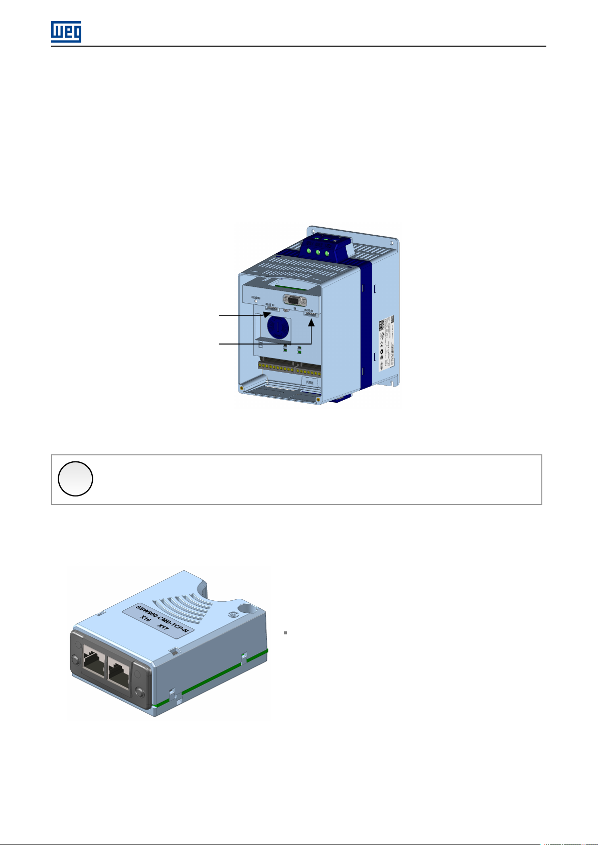
The SSW900 soft-starter has two Slots for accessories (Figura 2.1). Parameters S3.5.1 and S3.5.2 present which
accessory was recognized by Slot.
The accessories can be connected to any Slot, but only one type of each communication accessory is allowed. The
Anybus-CC communication accessories (regardless of the protocol implanted) are identified on these parameters as
Anybus-CC.
Read the user’s manual of the SSW900 soft-starter before installing or using this accessory.
Slot 1
Slot 2
Figure 2.1: Slots for accessories
NOTE!
✓
Only one Anybus-CC communication accessory can be connected to the SSW900 soft-starter, even
if they are different protocols.
2.1 ANYBUS MODBUS TCP ACCESSORY
SSW900-CMB-TCP-N:
Supplied items:
– Installation guide.
– Anybus Modbus TCP communication module.
– ”torx” screw driver for fixing the module.
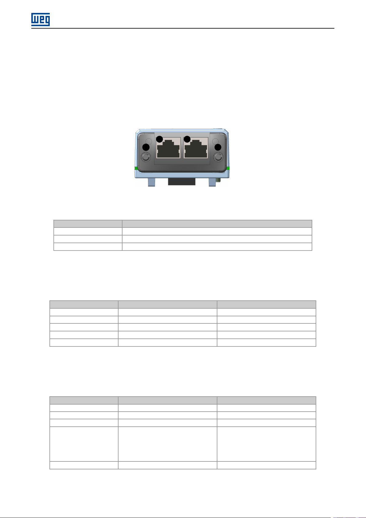
2.2 CONNECTORS
The accessory for Modbus TCP communication has two RJ45 connectors for network connection. The connector pin
out follows the Fast Ethernet 100BASE-TX standard, using two pairs of cables for data transmission and reception.
SSW900 | 8
INTERFACE DESCRIPTION
The housings of the Ethernet connectors, which are normally connected to the cable shield, have connections between themselves and to the protective earth via an RC circuit.
2.3 INDICATION LEDS
The Modbus TCP accessory has a Link LED indicator in each Ethernet connector (Ê and Ë), and two LEDs for state
indication, one for the communication module (MS) and another for the network (NS). These LEDs have the following
functions and indications.
1
MS
Table 2.1: Link LED
State Description
Off No link or powered off.
Green, solid Link up, no activity.
Green, flashing Link up and activity.
2
NS
The MS LED indicates the conditions of the module itself. That is, whether it is able to work or not. The table below
shows the possible states:
Table 2.2: State of the Modbus TCP module
Status Description Comments
Off No power or initializing Green, solid Normal operation Red, solid Module in error Reinitializing the equipment is required.
Red, flashing IP address is invalid/duplicated Flashing green/red Equipment performing self-diagnosis It occurs during initialization.
The NS LED provides information about the state of the Modbus TCP network. The table below presents the description of those states.
Table 2.3: State of the Modbus TCP network
Status Description Comments
Off No power or no IP address Green, solid Connection established Green, flashing Waiting for connections Red, solid Invalid/duplicated IP address, or fatal error Reinitializing the equipment is required. It in-
Flashing green/red Equipment performing self-diagnosis It occurs during initialization.
dicates that the slave cannot enter the network because of addressing problems. Verify if the address is being used by another
equipment or if there are installation problems.
SSW900 | 9

MODBUS TCP NETWORK INSTALLATION
3 MODBUS TCP NETWORK INSTALLATION
This chapter presents recommendations related to equipment installation in an Modbus TCP network.
3.1 IP ADDRESS
Every equipment in an Ethernet network needs an IP address and subnet mask.
The IP addressing is unique in the network, and each equipment must have a different IP. The subnet mask is used
to define which IP address range is valid in the network.
The SSW900 soft-starter allows the use of two methods for programming these features, programmable via C8.3.4:
Parameters: uses the configurations of IP address, mask and gateway as programmed on equipment parameters.
DHCP: enable the configuration of the SSW900 via DHCP server. The DHCP can automatically assign IP ad-
dresses, subnet mask, etc. to the devices on the network. The configurations performed via parameters are
disregarded.
NOTE!
✓
After changing these properties, for the changes to take effect, the equipment must be turned off and
on again, or requesting the settings update via C8.3.1.
3.2 COMMUNICATION RATE
The Ethernet interfaces of the SSW900 soft-starter can communicate using the 10 or 100 Mbps rates in half or full
duplex mode.
NOTE!
✓
It is important that, for each Ethernet connection made between two points, the baud rate and the
duplex mode are set to the same option. If the option AUTO is used in one of the points, you must set
the other point also to AUTO, or to half duplex mode.
3.3 CABLE
Recommended characteristics for the cable:
Standard Ethernet cable, 100Base-TX (FastEthernet), CAT 5e or higher.
Shielded cable.
Maximum length between devices: 100 m.
For installation, it is recommended the use of shielded Ethernet cables specific for use in industrial environment.
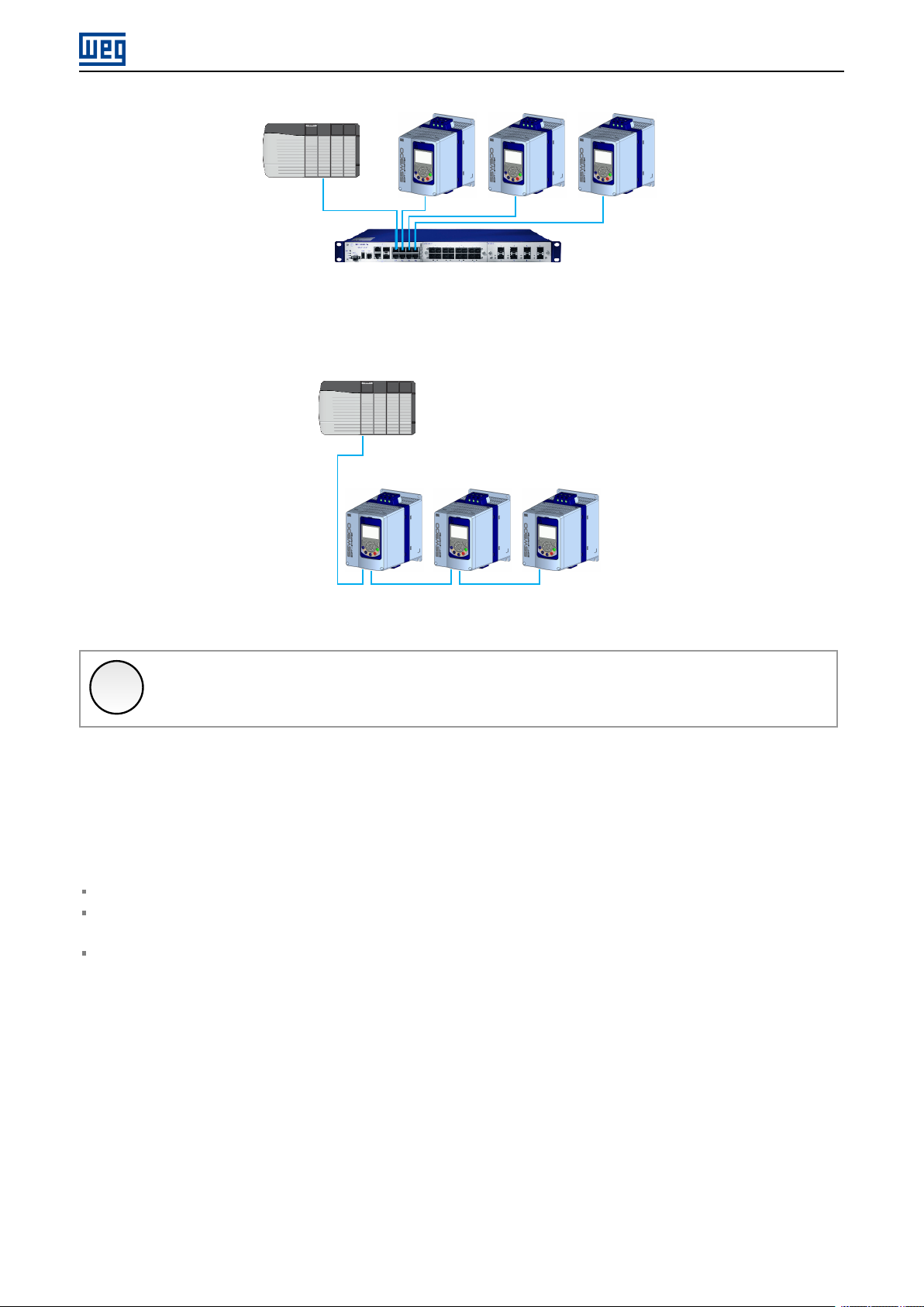
3.4 NETWORK TOPOLOGY
To connect SSW900 soft-starter in an Modbus TCP network, usually the star connection is made using an industrial
switch.
SSW900 | 10
MODBUS TCP NETWORK INSTALLATION
Figure 3.1: Star topology
It is also possible to make the connection in daisy chain, allowing a topology equivalent to a bus.
Figure 3.2: Daisy chain topology
NOTE!
✓
When the equipment is turned off, the built-in switch is also deactivated, preventing communication
with the subsequent equipment.
3.5 RECOMMENDATIONS FOR GROUNDING CONNECTION AND CABLE ROUTING
The correct connection with the ground decreases problems caused by interference in an industrial environment. The
following are some recommendations about grounding and cable routing:
Always use shielded twisted pair Ethernet cables and connectors with metallic housing.
Connect the equipment grounding via grounding terminal. Avoid the cable connection on multiple grounding
points, especially where there are grounds with different potentials.
Pass signal cables and communication cables in dedicated pathways. Prevent laying these cables next to power
cables.
SSW900 | 11

S STATUS
4 S STATUS
Allows viewing of the SSW reading variables.
S5 COMMUNICATIONS
HMI monitoring parameters of the communication interfaces.
For a detailed description, refer to the Modbus RTU and Anybus User’s Manuals of the SSW according to the interface
used.
S5.1 Status Word
.1 SSW 0 ... 15 Bit
Description:
Word of SSW status.
.1 SSW Word of SSW status.
Bit Value/Description
Bit 0
Running
Bit 1
Gener. Enabled
Bit 2
JOG
Bit 3
Initial Test
Bit 4
Ramp Up
Bit 5
Full Voltage
Bit 6
Bypass
Bit 7
Ramp Down
Bit 8
Remote
Bit 9
Braking
Bit 10
FWD/REV
Bit 11
Reverse
Bit 12
Ton
Bit 13
Toff
Bit 14
Alarm
Bit 15
Fault
0: The motor is not enabled.
1: The motor is enabled.
0: When it is general disabled by any mean.
1: When it is general enabled by all the means.
0: The JOG function is inactive.
1: The JOG function is active.
0: None.
1: During the initial tests before the motor starting.
0: It is not accelerating.
1: During the whole acceleration.
0: There is no full voltage applied to the motor.
1: Full voltage is being applied to the motor.
0: With open bypass.
1: With closed bypass.
0: It is not decelerating.
1: During the whole deceleration.
0: Local.
1: Remote.
0: It is not executing braking.
1: During the braking process.
0: It is not reverting the rotation direction.
1: During the rotation reversion process.
0: Forward rotation.
1: Reverse rotation.
0: None.
1: Time before start (C5.7.2).
0: None.
1: Time after stop (C5.7.3).
0: The SSW is not in alarm condition.
1: The SSW is in alarm condition.
Note: The active alarm codes can be read by means of the menu D2.1.
0: The SSW is not in fault condition.
1: The SSW is in fault condition.
Note: The active fault code can be read by means of the menu D1.1.
S5.2 Command Word
.5 Slot1 0 ... 15 Bit
.6 Slot2 0 ... 15 Bit
SSW900 | 12

S STATUS
Description:
Command word of all sources of the SSW. The RUN/STOP and JOG commands of the sources which are not active
will be reset.
.5 Slot1 Control word via any communication accessory connected to Slot 1.
.6 Slot2 Command word via any communication accessory connected to Slot 2.
Bit Value/Description
Bit 0
Start/Stop
Bit 1
Gener. Enabled
Bit 2
JOG
Bit 3
FWD/REV
Bit 4
LOC/REM
Bit 5 … 6
Reserved
Bit 7
Reset
Bit 8 … 15
Reserved
0: stopping by ramp.
1: starting by ramp.
0: general disable.
1: general enable.
0: no JOG.
1: with JOG.
0: clockwise CW.
1: counterclockwise CWW.
0: local.
1: remote.
0 → 1: execute fault reset (if a fault is active).
Note: Only in the 0 to 1 transition command.
NOTE!
✓
If the RUN/STOP and JOG commands are by a certain source and it is active, only these commands
can be viewed in S5.2. For security reasons, all the other commands of the other sources which are
not active will be reset.
S5.3 Value for Outputs
.1 DO Value 0 ... 15 Bit
Description:
Value for digital and analog outputs via serial communication.
.1 DO Value Value for the digital outputs via network interfaces.
Bit Value/Description
Bit 0
DO1
Bit 1
DO2
Bit 2
DO3
Bit 3 … 15
Reserved
0: Inactive.
1: Active.
0: Inactive.
1: Active.
0: Inactive.
1: Active.
S5.3.2 Value for AO
.1 AO in LSB 0 ... 1023
Description:
Value for the analog output via network interfaces.
.1 AO in LSB Value, Least Significant Bit, for the analog output via network interfaces: 0...1023. 0=0% e 1023=100%.
SSW900 | 13

S5.5 Anybus-CC
.1 Identification 0 ... 25
.2 Comm. Status 0 ... 8
Description:
Status of the Anybus communication accessory and the protocols that use this interface.
.1 Identification It allows identifying the connected Anybus module.
Indication Description
0 = Disabled Communication module not installed.
1 ... 15 = Reserved
16 = Profibus DP Profibus DP module.
17 = DeviceNet DeviceNet Module.
18 = Reserved
19 = EtherNet/IP EtherNet/IP module.
20 = Reserved
21 = Modbus TCP Modbus TCP module.
22 = Reserved
23 = PROFINET IO PROFINET IO module.
24 ... 25 = Reserved
S STATUS
.2 Comm. Status It informs the communication module status.
Indication Description
0 = Setup Module identified, waiting for configuration data (automatic).
1 = Init Module executing the interface initialization (automatic).
2 = Wait Comm Module initialized, but without communication with the network master.
3 = Idle Communication with the network master established, but in idle or programming mode.
4 = Data Active Communication with the network master established, and I/O data being communicated
5 = Error Not available.
6 = Reserved
7 = Exception Serious error on the communication interface. The interface requires reinitialization.
8 = Access Error Access error between the equipment and Anybus interface. Requires interface reset.
successfully. ”Online”.
SSW900 | 14
5 C CONFIGURATIONS
This menu allows the programming of all SSW configuration parameters.
C8 COMMUNICATION
To change information via communication network, the SSW has several standard protocols.
The following necessary accessories and protocols are available:
Protocol Accessory
Modbus RTU SSW900-CRS485-W
Profibus DP SSW900-CPDP-N
DeviceNet SSW900-CDN-N
EtherNet/IP SSW900-CETH-IP-N
Modbus TCP SSW900-CMB-TCP-N
PROFINET IO SSW900-CPN-IO
C CONFIGURATIONS
For further details regarding the SSW configuration to operate these protocols, refer to the SSW Communication
Manual.
C8.1 I/O Data
Configure network data exchange area.
Use this for cyclic communication over Anybus-CC for Profibus, DeviceNet, EtherNet/IP and PROFINET IO. For
RS485 using Modbus RTU protocol or Anybus-CC Modbus TCP module, a contiguous area of holding registers
(@1500-@1549 and @1600-@1619) can be accessed using standard Modbus functions.
Data write
{
{
Word #1 = Net Id
to
Word #10 = Net Id
Word #11 = Net Id
to
Word #20 = Net Id
Slot 1
1◦word = 1
Quantity = 25
Slot 2
1◦word =26
Quantity = 25
Data read
{
{
word #1 = Net Id
to
word #25 = Net Id
word #26 = Net Id
to
word #50 = Net Id
Figure 5.1: Example of data setting.
Slot 1
1◦Word = 1
Quantity = 10
Slot 2
1◦Word =11
Quantity = 10
C8.1.1 Data Read
Configure a set of 16 bit parameters to read over the network.
C8.1.1 Data Read
C8.1.1.1 Slot 1 1st Word
Range: 1 ... 50 Default: 1
Properties: Stopped
Description:
It sets the index of the first programmable read word for data communication (inputs for master).
SSW900 | 15

C CONFIGURATIONS
C8.1.1 Data Read
C8.1.1.2 Slot 1 Quantity
Range: 1 ... 50 Default: 1
Properties: Stopped
Description:
It sets the number of read words for data communication (inputs for master), from the first word on.
C8.1.1 Data Read
C8.1.1.3 Slot 2 1st Word
Range: 1 ... 50 Default: 26
Properties: Stopped
Description:
It sets the index of the first programmable read word for data communication (inputs for master).
C8.1.1 Data Read
C8.1.1.4 Slot 2 Quantity
Range: 1 ... 50 Default: 1
Properties: Stopped
Description:
It set the number of read words for data communication (inputs for master), from the first word on.
C8.1.1 Data Read
C8.1.1.5 Word #1
C8.1.1.5 to C8.1.1.54
C8.1.1 Data Read
C8.1.1.54 Word #50
Range: 0 ... 65535 Default: 0
Properties: Stopped
Description:
Select the net address of other parameter, which content will be available as reading data for fieldbus interfaces
(inputs: sent to master).
The data size of the referenced parameter must be considered. If data size is bigger than 16 bits, the next data read
word configuration must be set to the same net address.
C8.1.2 Data Write
Configure a set of 16 bit parameters to write over the network.
C8.1.2 Data Write
C8.1.2.1 Slot 1 1st Word
Range: 1 ... 20 Default:
Properties: Stopped
Description:
It sets the index of the first programmable write word for data communication (outputs for master).
C8.1.2 Data Write
C8.1.2.2 Slot 1 Quantity
Range: 1 ... 20 Default: 1
Properties: Stopped
SSW900 | 16
1
C CONFIGURATIONS
Description:
It sets the number of write words for data communication (outputs for master), from the first word on.
C8.1.2 Data Write
C8.1.2.3 Slot 2 1st Word
Range: 1 ... 20 Default: 11
Properties: Stopped
Description:
It sets the index of the first programmable write word for data communication (outputs for master).
C8.1.2 Data Write
C8.1.2.4 Slot 2 Quantity
Range: 1 ... 20 Default: 1
Properties: Stopped
Description:
It sets the number of write words for data communication (outputs for master), from the first word on.
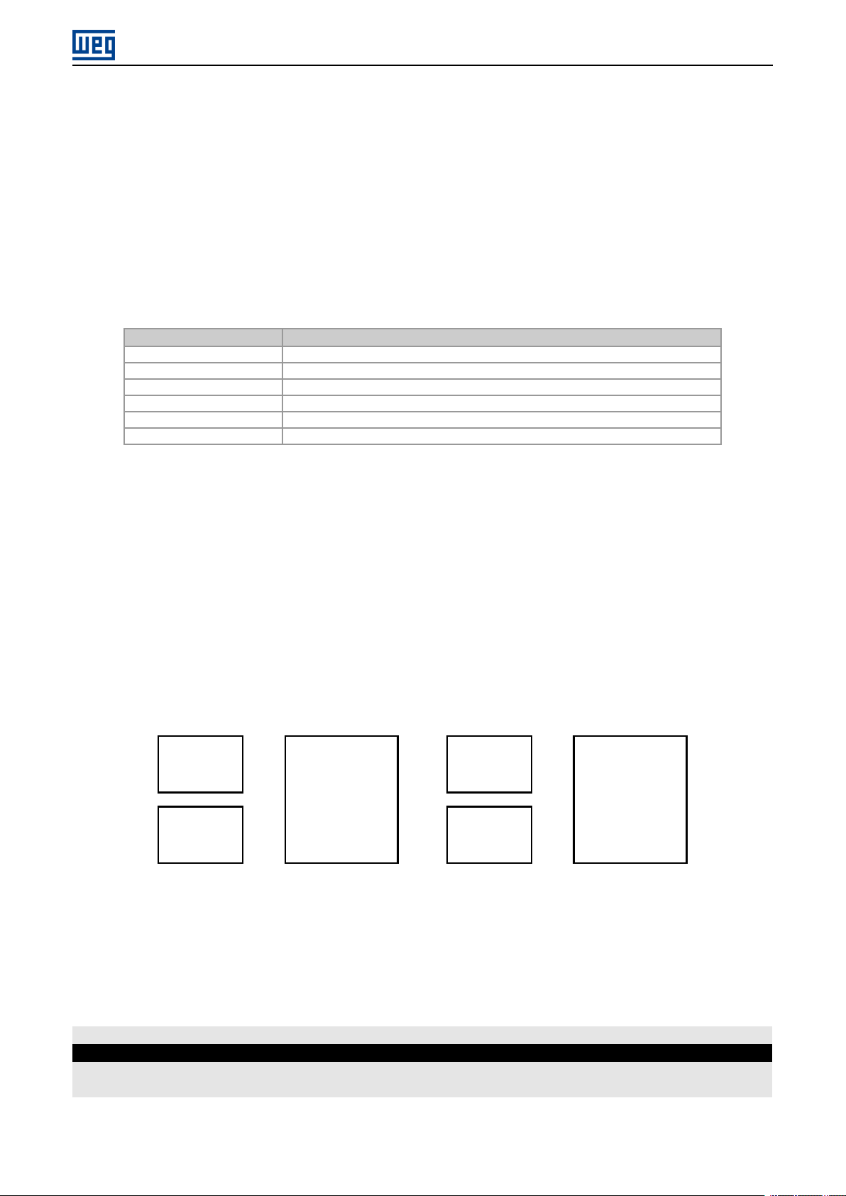
C8.1.2 Data Write
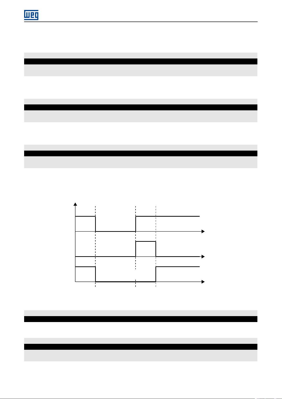
C8.1.2.5 Update Delay
Range: 0.0 ... 999.9 s Default: 0.0
Properties:
Description:
Whenever there is a transition from offline (without cyclic data) to online (with cyclic write data), the data received via
communication networks (write words) is ignored during this programmed time, remaining in the state it was before
the beginning of the reception.
Online Offline Online
Delay
Not updated
writing words
0
Figure 5.2: Delay in the update of the I/O words.
Updates
writing words
t(s)
C8.1.2 Data Write
C8.1.2.6 Word #1
C8.1.2.6 to C8.1.2.25
C8.1.2 Data Write
C8.1.2.25 Word #20
Range: 0 ... 65535 Default: 0
Properties: Stopped
Description:
Select the net address of other parameter, which content will be available as writing data for fieldbus interfaces
(outputs: received from master).
SSW900 | 17

C CONFIGURATIONS
The data size of the referenced parameter must be considered. If data size is bigger than 16 bits, the next data write
word configuration must be set to the same net address.
C8.3 Anybus-CC
Configuration for the Anybus-CC communication and protocols that use this interface.
For a detailed description, refer to the SSW900 Anybus-CC User’s Manual specific for the desired protocol, supplied
in electronic format.
C8.3 Anybus-CC
C8.3.1 Update Configuration
Range: 0 ... 1 Default: 0
Properties: Stopped
Description:
It allows forcing a reinitialization of the Anybus-CC communication module for the configurations done in the parameters of menus C8.1 and C8.3 to be applied.
The reinitialization implies communication loss. After the process is completed, this parameter automatically goes
back to Regular Operation.
Indication Description
0 = Normal Operation No action.
1 = Update configuration Reinitializes the Anybus module.
C8.3 Anybus-CC
C8.3.4 IP Address Configuration
Range: 0 ... 2 Default: 1
Properties:
Description:
It allows to choose how to set the IP address for the modules Anybus-CC EtherNet/IP, Modbus TCP and PROFINET
IO.
Indication Description
0 = Parameters The programming of the IP address, configurations of the subnet mask and gateway
1 = DHCP Enables the DHCP function. The IP address and other network configurations are re-
2 = DCP The IP address and other network configurations are received via DCP (PROFINET IO).
must be done through parameters C8.3.5, C8.3.6 and C8.3.7.
ceived from a DHCP server via network.
NOTE!
✓
C8.3 Anybus-CC
C8.3.5 IP Address
Range: 0.0.0.0 ... 255.255.255.255 Default: 192.168.0.10
Properties:
Description:
It allows programming the IP address of the module Anybus-CC EtherNet/IP, Modbus TCP or PROFINET IO. It is only
effective if C8.3.4 = Parameters.
After changing this configuration, for the modification to be effective, the equipment must be turned off
and then turned on again, or the configurations must be updated through C8.3.1.
SSW900 | 18

C CONFIGURATIONS
NOTE!
✓
After changing this configuration, for the modification to be effective, the equipment must be turned off
and then turned on again, or the configurations must be updated through C8.3.1.
C8.3 Anybus-CC
C8.3.6 CIDR
Range: 0 ... 31 Default: 24
Properties:
Description:
It allows programming the subnet mask used by the module Anybus-CC EtherNet/IP, Modbus TCP or PROFINET IO.
It is only effective if C8.3.4 = Parameters.
Indication Description
0 = Reserved
1 = 128.0.0.0 Subnet mask.
2 = 192.0.0.0 Subnet mask.
3 = 224.0.0.0 Subnet mask.
4 = 240.0.0.0 Subnet mask.
5 = 248.0.0.0 Subnet mask.
6 = 252.0.0.0 Subnet mask.
7 = 254.0.0.0 Subnet mask.
8 = 255.0.0.0 Subnet mask.
9 = 255.128.0.0 Subnet mask.
10 = 255.192.0.0 Subnet mask.
11 = 255.224.0.0 Subnet mask.
12 = 255.240.0.0 Subnet mask.
13 = 255.248.0.0 Subnet mask.
14 = 255.252.0.0 Subnet mask.
15 = 255.254.0.0 Subnet mask.
16 = 255.255.0.0 Subnet mask.
17 = 255.255.128.0 Subnet mask.
18 = 255.255.192.0 Subnet mask.
19 = 255.255.224.0 Subnet mask.
20 = 255.255.240.0 Subnet mask.
21 = 255.255.248.0 Subnet mask.
22 = 255.255.252.0 Subnet mask.
23 = 255.255.254.0 Subnet mask.
24 = 255.255.255.0 Subnet mask. Factory setting.
25 = 255.255.255.128 Subnet mask.
26 = 255.255.255.192 Subnet mask.
27 = 255.255.255.224 Subnet mask.
28 = 255.255.255.240 Subnet mask.
29 = 255.255.255.248 Subnet mask.
30 = 255.255.255.252 Subnet mask.
31 = 255.255.255.254 Subnet mask.
NOTE!
✓
After changing this configuration, for the modification to be effective, the equipment must be turned off
and then turned on again, or the configurations must be updated through C8.3.1.
C8.3 Anybus-CC
C8.3.7 Gateway
Range: 0.0.0.0 ... 255.255.255.255 Default: 0.0.0.0
Properties:
SSW900 | 19
 Loading...