

WEG SSW-08 User Manual
Soft-Starter
Arrancador Suave
Soft-Starter
SSW-08
Motors | Automation | Energy | Transmission & Distribution | Coatings
User's Manual
Manual del Usuario
Manual do Usuário

Soft-Starter User’s Guide
Manual del Usuario del Arrancador Suave
Manual do Usuário da Soft-Starter
Serie: SSW-08
English / Español / Português
Document: 10000008521 / 03
Date/Data: 03/2011
Summary of revisions / Sumario de las revisiones /
Sumário das revisões
The information below describes the revisions in this manual.
Revision Description Chapter
1 First Edition 2 Size 4 included -
3
Revision after the size 4 UL certification.
Changed: item 3.2; figure 3.4; figure 3.5; item 3.2.4.1;
3.2.4.2; 3.2.7; 3.3; 5.2.2; E77 in the table 6.1; table 8.1.
Included new functions of software version V1.4x.
3, 4, 5, 6, 8
La información abajo describe las revisiones ocurridas em este manual.
Revisión Descripción Capítulo
1 Primer Edición 2 Inclusión Mecánica 4 -
3
Corrección luego de la certificación UL de la mecánica 4.
Modificado: item 3.2; figura 3.4; figura 3.5; item 3.2.4.1;
3.2.4.2; 3.2.7; 3.3; 5.2.2; E77 en la tabla 6.1; tabla 8.1.
Inclusión de las nuevas funciones
de la version de software V1.4x.
3, 4, 5, 6, 8
As informações abaixo descrevem as revisões ocorridas neste manual.
Revisão Descrição Capítulo
1 Primeira Edição 2 Inclusão da mecânica 4 -
3
Correção depois da certificação UL da mecânica 4.
Alterado: item 3.2; figura 3.4; figura 3.5; item 3.2.4.1;
3.2.4.2; 3.2.7; 3.3; 5.2.2; E77 na tabela 6.1; tabela 8.1.
Inclusão das novas funções
da versão de software V1.4x.
3, 4, 5, 6, 8

Summary
1. SAFETY INSTRUCTIONS
1.1 SAFETY NOTICES IN THE MANUAL ................................................................................................ 1
1.2 SAFETY NOTICES ON THE PRODUCT ............................................................................................1
1.3 PRELIMINARY RECOMMENDATIONS .............................................................................................1
2. GENERAL INFORMATION
2.1 ABOUT THIS MANUAL ...................................................................................................................... 3
2.2 ABOUT THE SOFT-STARTER SSW-08 ............................................................................................3
2.3 SOFT-STARTER SSW-08 IDENTIFICATION PLATE .......................................................................5
2.4 RECEIVING AND STORAGE .............................................................................................................7
3. INSTALLATION AND CONNECTION
3.1 MECHANICAL INSTALLATION .........................................................................................................8
3.1.1 Environmental Conditions ........................................................................................................8
3.1.2 Soft-Starter SSW-08 Dimensions ...........................................................................................8
3.1.3 Mounting Specifications ..........................................................................................................9
3.1.3.1 Mounting Inside a Panel ............................................................................................10
3.1.3.2 Mounting on Surface ................................................................................................. 11
3.2 ELECTRICAL INSTALLATION ......................................................................................................... 11
3.2.1 Power Terminals .....................................................................................................................12
3.2.2 Location of the Grounding, Control and Power Connections .......................................... 13
3.2.3 Recommended Power and Grounding Cables ...................................................................13
3.2.4 Power Supply Connection to the Soft-Starter SSW-08 ..................................................... 14
3.2.4.1 Power Supply Capacity .............................................................................................15
3.2.4.2 Recommended Fuses ................................................................................................15
3.2.4.3 Recommended Contactors ......................................................................................16
3.2.5 Soft-Starter SSW-08 Connection to the Motor ..................................................................16
3.2.5.1 Standard Three-Wire Connection ............................................................................ 17
3.2.6 Grounding Connections ........................................................................................................17
3.2.7 Control and Signal Connections ..........................................................................................19
3.3 RECOMMENDED SET-UPS ............................................................................................................20
3.3.1 Recommended Set-up with Command via Two-wire Digital Inputs and
Isolation Contactor ..........................................................................................................................21
3.3.2 Recommended Set-up with Command via Three-wire Digital Inputs and ....................21
Circuit-Breaker ................................................................................................................................21
3.3.3 Recommended Set-up with Command via Two-wire Digital Inputs and
Direction of Rotation .......................................................................................................................22
3.3.4 Recommended Set-up with Command via Two-wires Digital Inputs and DC-Braking .23
3.3.5 Symbols ...................................................................................................................................24
4. SETTING THE SSW-08
4.1 CONTROL TYPE SETTING ..............................................................................................................25
4.2 KICK START .....................................................................................................................................26
4.3 INITIAL VOLTAGE SETTING ............................................................................................................26
4.4 CURRENT LIMIT SETTING .............................................................................................................27
4.5 ACCELERATION RAMP TIME SETTING ........................................................................................28
4.6 DECELERATION RAMP TIME SETTING ........................................................................................28
4.7 MOTOR CURRENT SETTING ..........................................................................................................29
4.8 MOTOR ELECTRONIC OVERLOAD PROTECTION .......................................................................30
4.9 RESET ...............................................................................................................................................32
4.10 DI2 DIGITAL INPUT SETTING .......................................................................................................32
4.11 OUTPUT RELAY OPERATION .......................................................................................................33
4.12 RELAY OUTPUT RL1 PROGRAMMING ........................................................................................33

Summary
5. PROGRAMMING INFORMATION AND SUGGESTIONS
5.1 APPLICATIONS AND PROGRAMMING ..........................................................................................34
5.1.1 Voltage Ramp Starting ...........................................................................................................35
5.1.2 Current Limit Starting ............................................................................................................36
5.1.3 Starting with Pump Control (P202 = 2) .................................................................................36
5.1.4 Programming the control type in pump control .................................................................38
5.2 PROTECTIONS AND PROGRAMMING ..........................................................................................38
5.2.1 Suggestion on How to Program the Thermal Class ...........................................................38
5.2.2 Service Factor......................................................................................................................... 41
6. SOLUTION AND TROUBLESHOOTING
6.1 FAULTS AND POSSIBLE CAUSES ..................................................................................................43
6.2 TROUBLESHOOTING ......................................................................................................................46
6.3 PREVENTIVE MAINTENANCE ........................................................................................................47
7. OPTIONS AND ACCESSORIES
7.1 IP20 KIT .............................................................................................................................................48
8. TECHNICAL CHARACTERISTICS
8.1 NOMINAL POWERS AND CURRENTS ACCORDING TO UL508 .................................................49
8.2 NOMINAL POWERS AND CURRENTS FOR STANDARD IP55, IV POLE WEG MOTOR ............49
8.3 POWER DATA ...................................................................................................................................50
8.4 ELECTRONICS AND PROGRAMMING DATA ................................................................................50
1
Safety Instructions
SSW-08 | 1
1. SAFETY INSTRUCTIONS
This Manual contains the necessary information for the correct use of the Soft-Starter SSW-08.
It was written to be used by qualified personnel with suitable training or technical qualifications
to operate this type of equipment.
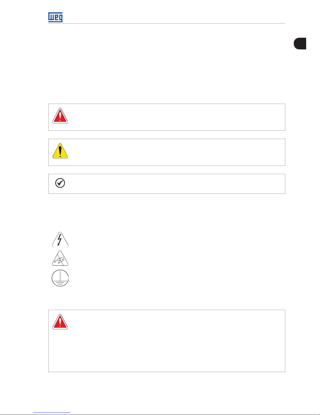
1.1 SAFETY NOTICES IN THE MANUAL
The following safety notices will be used in the text.
DANGER!
Failure to observe the recommended procedures may lead to serious or fatal injuries
and considerable material damage.
ATTENTION!
Failure to observe the recommended procedures in this notice may lead to material
damage.
NOTE!
Important information for the correct understanding and good function of the product.
1.2 SAFETY NOTICES ON THE PRODUCT
The following symbols may be attached to the product as a safety notice.
High Voltages.
Components are sensitive to electrostatic discharge.
Do not touch them.
Mandatory connection to ground protection (PE).
1.3 PRELIMINARY RECOMMENDATIONS
DANGER!
Only personnel with suitable qualification and familiar with the Soft-Starter SSW-08 and
associated equipment should plan or implement the installation, start-up, operation
and maintenance of this equipment.
These personnel must follow all safety instructions in this manual and/ or defined by
local regulations.
Failure to follow these safety instructions may result in personnel injury and/or
equipment damage.
1
Safety Instructions
2 | SSW-08
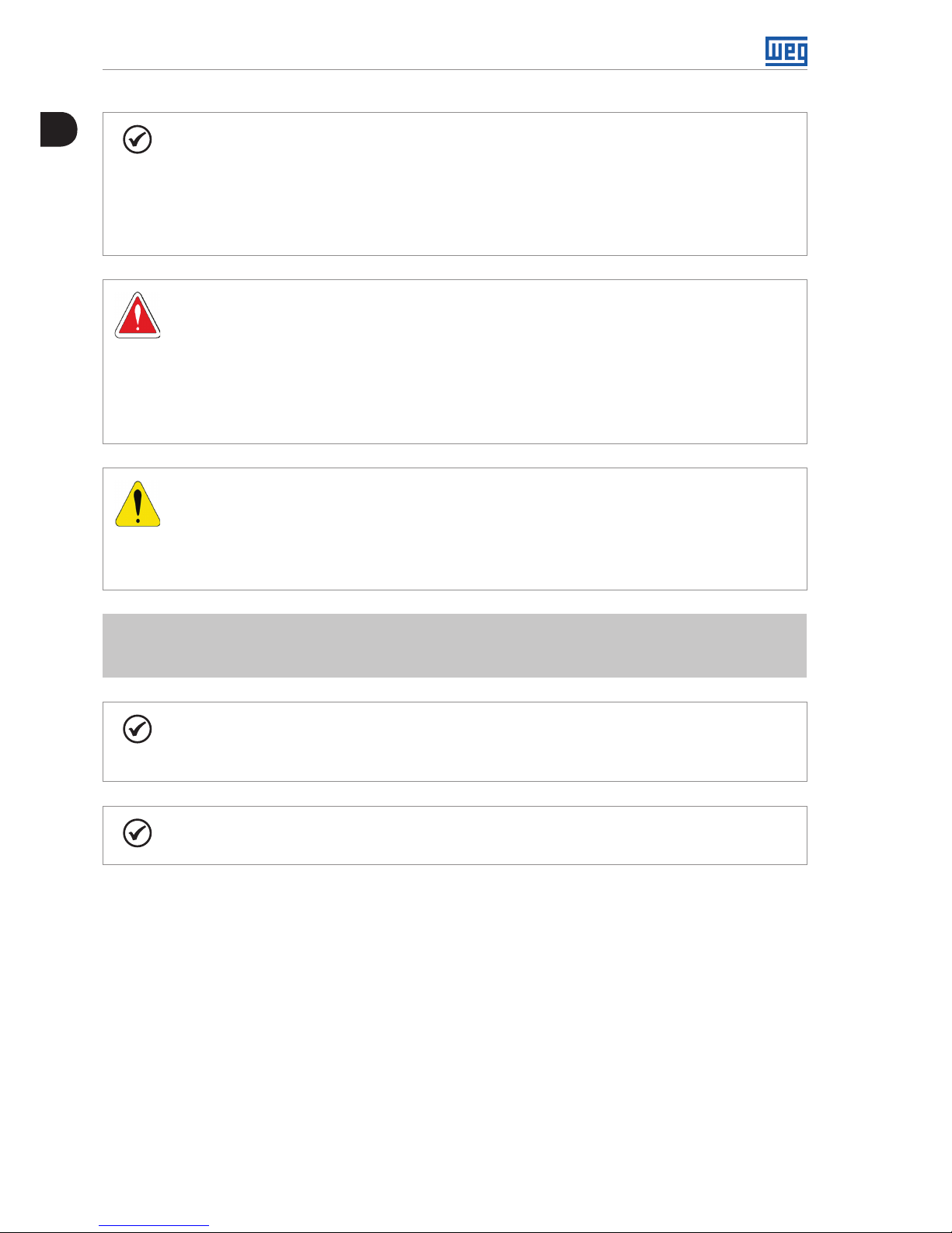
NOTE!
In this Manual, qualified personnel are those trained to:
1. Install, ground, power-up, and operate the Soft-Starter SSW-08 according to this
manual and the required safety procedures;
2. Use protection equipment according to established regulations;
3. Give First Aid.
DANGER!
Always disconnect the general power supply before touching any electrical component
associated to the Soft-Starter SSW-08.
High voltage may be present even after the power supply is disconnected. Wait at
least 3 minutes for the total discharge of the capacitors.
Always connect the equipment’s heatsink to the protection ground (PE), at the proper
connection point.
ATTENTION!
All electronic boards have components that are sensitive to electrostatic discharges.
Do not touch these components or connectors directly.
If necessary, first touch the grounded metallic heatsink or use a suitable grounded
wrist strap.
Do not apply any high voltage test on the Soft-Starter SSW-08!
If necessary, contact the manufacturer.
NOTE!
Soft-Starters SSW-08 may interfere with other electronic equipment. Follow the
measures in Chapter 3 to reduce these effects.
NOTE!
Read this manual completely before installing or operating the Soft-Starter SSW-08.
2
General Information
SSW-08 | 3
2. GENERAL INFORMATION
2.1 ABOUT THIS MANUAL
This manual presents the Soft-Starter installation, how to start it up, its main technical
characteristics and how to identify and correct the most common problems. The manuals listed
next must be consulted in order to get more information regarding the functions, accessories
and working conditions:
Programming Manual, with a detailed description of the parameters and its functions;
RS232 / RS485 Communication Manual.
These manuals are supplied in electronic format on the CD-ROM that accompanies the
Soft-Starter, or can be obtained at WEG’s web site: http://www.weg.net.
2.2 ABOUT THE SOFT-STARTER SSW-08
The Soft-Starter SSW-08 is a high performance product with 2 phases controled that permits
the start control of the three phase AC induction motors. Thus, it prevents mechanical shocks
on the load and current peaks in the supply line.
The SSW-08 electronic Soft-Starter has been designed to drive three-phase induction motors
applied to light duty loads, such as centrifugal pumps, small fans and screw compressors. If the
Soft-Starter shall be applied on heavy duty loads, please contact WEG.
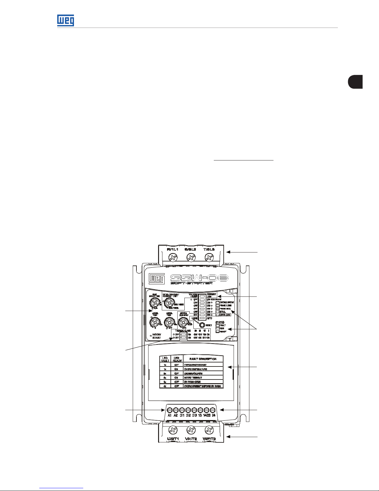
Three-phase
Power Supply
DIP Switch for
Soft-Starter adjustmente
and protection enabling
Status Indication LEDs
of the SSW-08
Lid for optional Plug-in
Modules
Relay Output
(13, 14/23 and 24)
Motor Output
Electronic Power
Supply
(A1 and A2)/
Start/Stop
Command of the
Motor (D1) and
Reset
(DI2 and DI3)
DIP switch to adjust
the Thermal Class
Trimpots to adjust
Figure 2.1: Frontal view of the SSW-08
2
General Information
4 | SSW-08
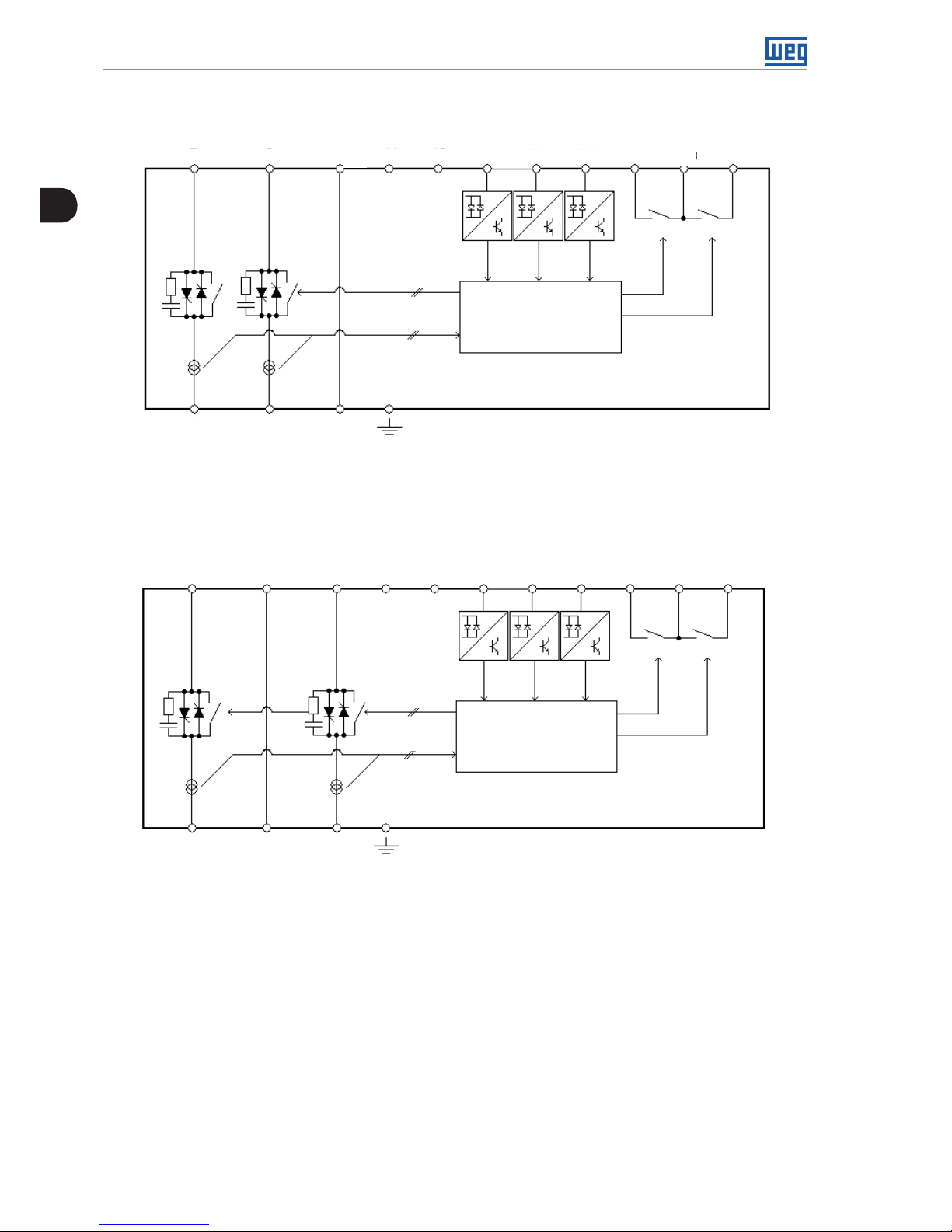
Three-Phase
Power Supply
Control
Power Supply
Programmable
Digital Inputs
Programmable Digital
Outputs
Three-Phase Motor
Digital Signal
Processor
DSP
R
S
T
A1
A2
Dl2
Dl3
13
14/23
24
Dl1
2 x
2 x
RL1
RL2
U
V W
PE
Figure 2.2.1: Soft-Starter SSW-08 size 1,2 and 3 block diagram
Three-Phase
Power Supply
Control
Power Supply
Programmable
Digital Inputs
Programmable Digital
Outputs
Three-Phase Motor
Digital Signal
Processor
DSP
R
S
T
A1
A2
Dl2
Dl3
13
14/23
24
Dl1
2 x
2 x
RL1
RL2
U
V W
PE
Figure 2.2.2: Soft-Starter SSW-08 Size 4 block diagram
2
General Information
SSW-08 | 5
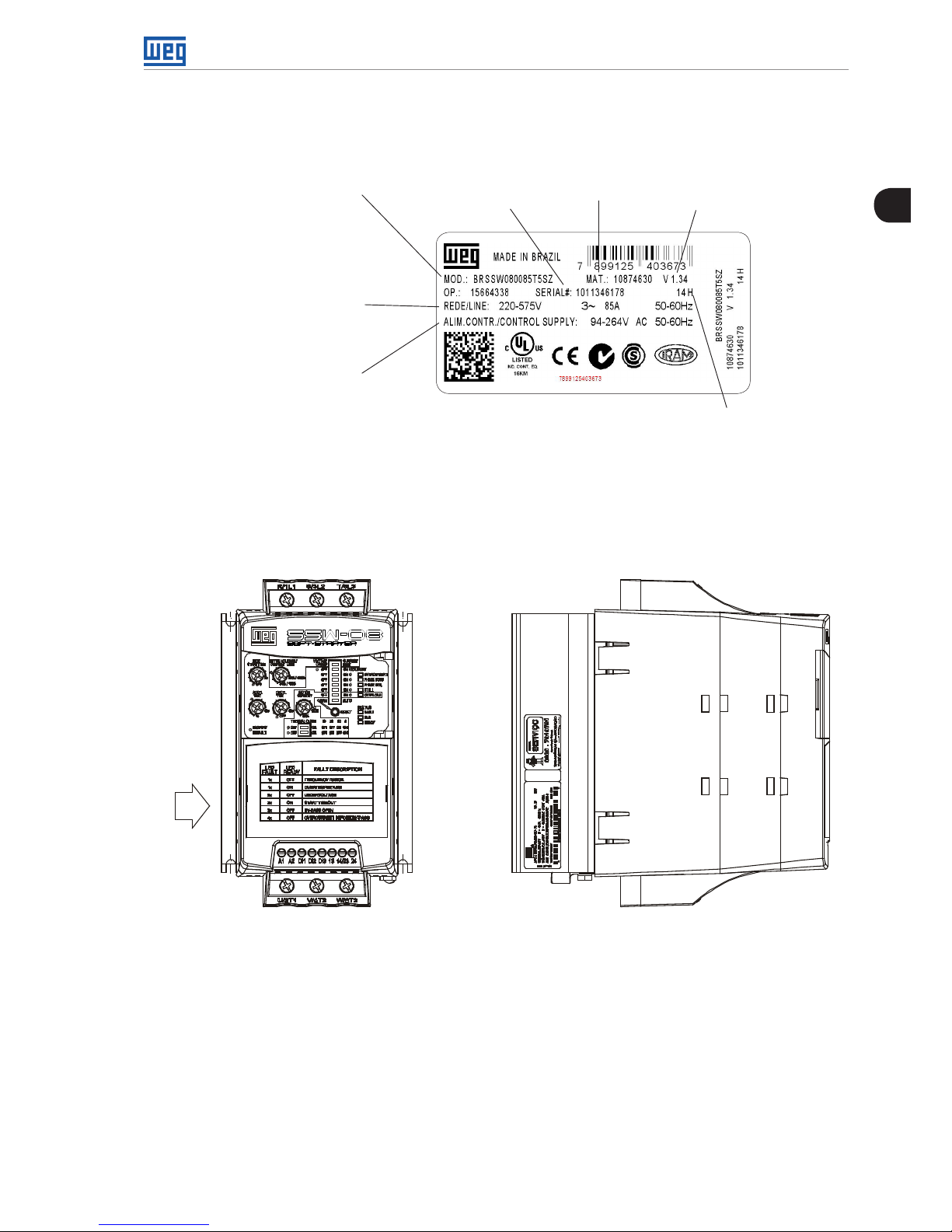
2.3 SOFT-STARTER SSW-08 IDENTIFICATION PLATE
SSW-08 Model
Input Data (Voltage,
Number of Phases,
Current and Frequency)
Control Power Supply Data
(Voltage, Frequency)
Serial
Number
Software
Version
Manufacturing date
(14 corresponds to
week and H to year)
WEG
Stock Item
Number
Figure 2.3: Soft-Starter SSW-08 identification plate
Position of the Identification Plate on the Soft-Starter SSW-08:
X
FRONTAL VIEW X VIEW
Figure 2.4: Detail of the Soft-Starter SSW-08 identification plate
2
General Information
6 | SSW-08
HOW TO SPECIFY THE SSW-08 MODEL:
EX SSW08 0017 T 5 S _ _ _ _ _ _ Z
Market/Manual
BR = Brazil
EX = Export
WEG Soft-Starter
Series SSW-08
SSW-08
Nominal Current
0017 = 17 A
0024 = 24 A
0030 = 30 A
0045 = 45 A
0061 = 61 A
0085 = 85 A
0130 = 130 A
0171 = 171 A
0200 = 200 A
0255 = 255 A
0312 = 312 A
0365 = 365 A
0412 = 412 A
Three-Phase
Power Supply
220-575 Vac Optional:
S = Standard
O = with
Optional
Degree of
Protection
Blank =
Standard
IP=IP20
(1)
Special
Hardware
Blank =
Standard
H1=Electronics
supply: 110 to
130 Vac
(2)
H2=
Electronics
supply: 208
to 240 Vac
(2)
Special
Software
Blank =
Standard
End of
Code
(1) Only for models 130 A to 412 A.
(2) Only for the 255 to 412A models.
REMARQUE!
The option field (S or O) defines if the Soft-Starter SSW-08 will be a standard version or if it will include any optional. If standard, the code
ends here.
Always put the letter Z at the end. For example:
EXSSW080017T5SZ = Standard Soft-Starter SSW-08 with 17 A and 220 V to 575 V to three-phase input with the User’s Guide in English,
Spanish and Portuguese.
If there is any optional, the fields must be filled out in the correct sequence until the code is completed with the letter Z.
The standard product as defined by this code is described as:
Degree of Protection: IP20 from 17 A to 85 A and IP00 from 130 A to 412 A.
2
General Information
SSW-08 | 7
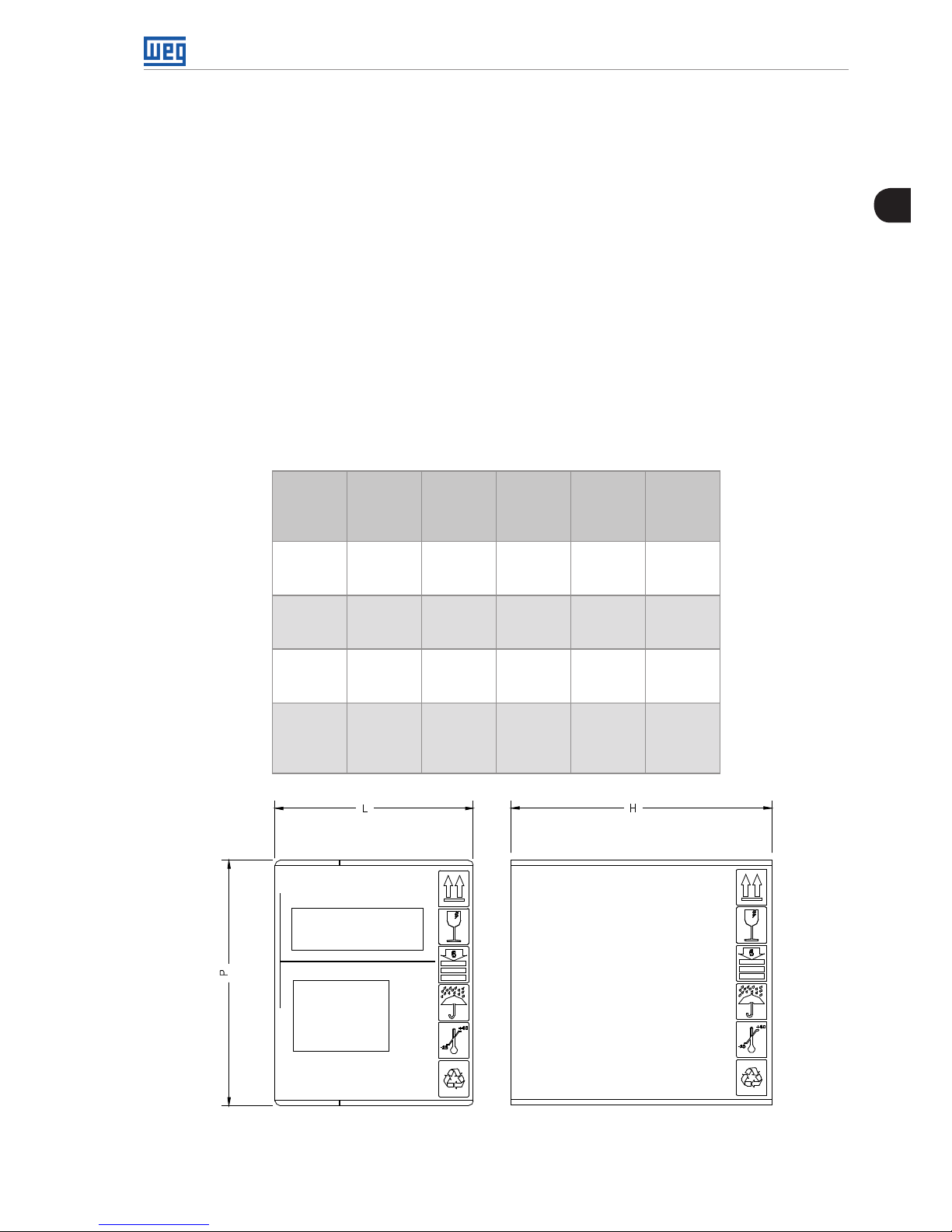
2.4 RECEIVING AND STORAGE
The Soft-Starter SSW-08 is supplied in a cardboard box. On the outside of the package there
is an identification plate which is identical to the one placed on the Soft-Starter SSW-08.
To open the package:
1- Put it on a table;
2- Open the package;
3- Take out the Soft-Starter.
Check if:
The Identification plate of the Soft-Starter SSW-08 matches the model purchased:
Damage has occurred during transport. If so, contact the carrier immediately.
If the Soft-Starter SSW-08 is not installed immediately, store it in its package in a clean and
dry place with temperature between -25 °C (-13 °F) and 65 °C (149 °F). 1 hour at -40 °C (-40 °F)
is permitted.
Table 2.1: Dimensions of the package in mm (in)
SSW-08
Model
Height
H
mm
(in)
Width
L
mm
(in)
Depth
P
mm
(in)
Volume
cm
3
(in3)
Weight
kg
(lb)
17 A
24 A
30 A
221
(8.70)
180
(7.09)
145
(5.71)
5768
(352.2)
1.65
(3.64)
45 A
61 A
85 A
260
(10.24)
198
(7.80)
245
(9.65)
12613
(770.8)
3.82
(8.42)
130 A
171 A
200 A
356
(14.02)
273
(10.75)
295
(11.61)
28670
(1750)
8.36
(18.43)
255 A
312 A
365 A
412 A
415
(16.34)
265
(10.43)
320
(12.6)
35192
(2147)
10.5
(23.2)
Figure 2.5: Dimensions of the package
3
Installation and Connection
8 | SSW-08
3. INSTALLATION AND CONNECTION
This chapter describes the procedures for the electrical and mechanical installation of the SoftStarter SSW-08. The guidelines and suggestions must be followed for the correct operation of
the Soft-Starter SSW-08.
3.1 MECHANICAL INSTALLATION
3.1.1 Environmental Conditions
The location of the Soft-Starters SSW-08 is an important factor to assure the correct operation
and high product reliability.
Avoid:
Direct exposure to sunlight, rain, high moisture and sea air ;
Exposure to explosive or corrosive gases and liquids;
Exposure to excessive vibration, dust or any metallic and/or oil particles in the air.
Allowed Environmental Conditions:
Surrounding air Temperature: 0 ºC to 55 ºC (32 ºF to 131 ºF) - nominal conditions.
Relative air moisture: 5 % to 90 %, with no-condensation.
Maximum altitude: 1,000 m (3,300 ft) above sea level - nominal conditions. From, 1,000 m
to 4,000 m (3,300 ft to 13,200 ft) above sea level – current reduction of 1 % for each 100 m
(330 ft) above 1,000 m (3,300 ft).
Pollution degree: 2 (according to the UL508).
Normally, only non conductive pollution. Condensation must not cause conduction in the
particles in the air.
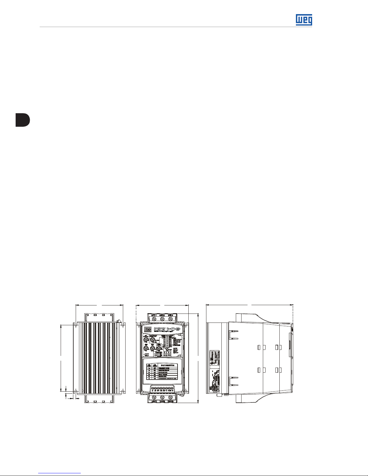
3.1.2 Soft-Starter SSW-08 Dimensions
The external dimensions and mounting holes are shown in figure 3.1 and table 3.1 below.
A
L
P
C
D
B
H
Figure 3.1: SW-08 dimensions
3
Installation and Connection
SSW-08 | 9
Table 3.1: Installation data with dimensions in mm (in)
SSW-08
Model
Height
H
mm
(in)
Width
L
mm
(in)
Depth
P
mm
(in)
A
mm
(in)
B
mm
(in)
C
mm
(in)
D
mm
(in)
Mountin
Screw
Weight
kg
(lb)
Degree
of
Protection
17 A
24 A
30 A
162
(6.38)
95
(3.74)
157
(6.18)85(3.35)
120
(4.72)5(0.20)4(0.16) M4
1.3
(2.9) IP20
45 A
61 A
85 A
208
(8.19)
144
(5.67)
203
(7.99)
132
(5.2)
148
(5.83)6(0.24)
3.4
(0.13) M4
3.3
(7.28) IP20
130 A
171 A
200 A
276
(10.9)
223
(8.78)
220
(8.66)
208
(8.19)
210
(8.27)
7.5
(0.3)
5
(0.2) M5
7.6
(16.8)
IP00 *
255 A
312 A
365 A
412 A
331
(13.0)
227
(8.94)
242
(9.53)
200
(7.87)
280
(11.0)15(0.59)9(0.35)
M8
9.2
(20.32)
IP00 *
* IP20 with optional.
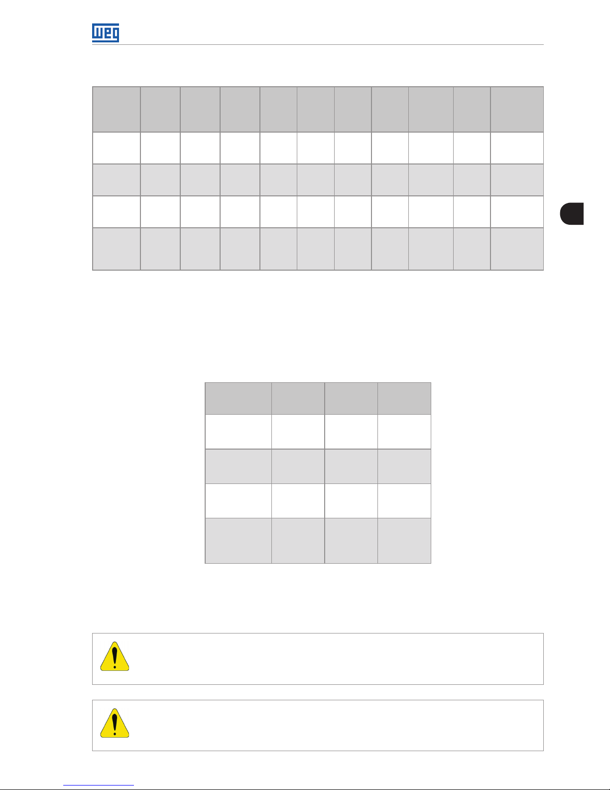
3.1.3 Mounting Specifications
To install the Soft-Starter SSW-08 leave at least the free spaces surrounding the Soft-Starter
as in figure 3.2 below. The dimensions of these free spaces are described in table 3.2.
Table 3.2: Recommended free spaces
SSW-08
Model
A
mm
(in)
B
mm
(in)
C
mm
(in)
17 A
24 A
30 A
50
(2)
50
(2)
30
(1.2)
45 A
61 A
85 A
80
(3.2)
80
(3.2)
30
(1.2)
130 A
171 A
200 A
100
(4)
100
(4)
30
(1.2)
255 A
312 A
365 A
412 A
150
(6)
150
(6)
30
(1.2)
Install the Soft-Starter SSW-08 in the vertical position according to the following recommendations:
1) Install on a reasonably flat surface;
2) Do not put heat sensitive components immediately above the Soft-Starter SSW-08.
ATTENTION!
If a Soft-Starter SSW-08 is installed on top of another use the minimum distance
A + B and diverge from the top Soft-Starter the hot air that comes from the one beneath it.
ATTENTION!
Independent conduits or cable trays must be planned for physic separation of signal,
control and power cables. (Refer to item 3.2 Electric Installation).
3
Installation and Connection
10 | SSW-08
Air Flow
Inlet
Air Flow
Outlet
A
B
C
Figure 3.2: Free spaces for ventilation
3.1.3.1 Mounting Inside a Panel
For Soft-Starters SSW-08 installed in panels or closed metallic boxes exhaustion/cooling is
required so the temperature does not exceed the maximum allowed. Refer to dissipated nominal
power in table 3.3.
Table 3.3: Dissipated power for ventilator panel dimensioning
SSW-08
Model
Dissipated
Power
in the
electronics
(W)
Average Power
dissipated
10 starts/h
3 x In @ 20 s
(W)
Total Average
Power
dissipated
10 starts/h
3 x In @ 20 s
(W)
17 A 12 6.8 18.8
24 A 12 9.6 21.6
30 A 12 12 24
45 A 12 18 30
61 A 12 24.4 36.4
85 A 12 34 46
130 A 12 52 64
171 A 12 68.4 80.4
200 A 12 80 92
255 A 36 102 138
312 A 36 125 161
365 A 36 146 182
412 A 36 165 201
3
Installation and Connection
SSW-08 | 11
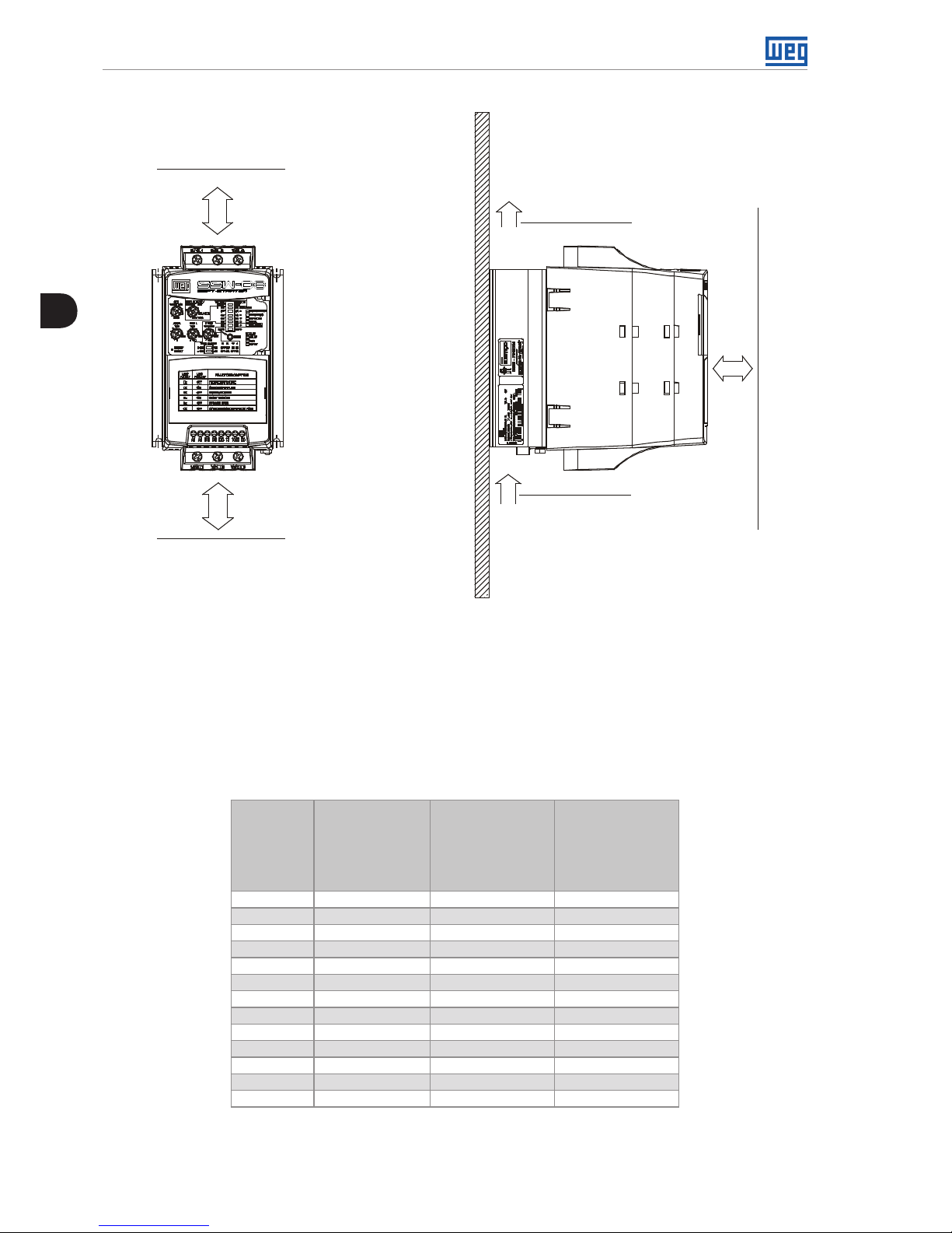
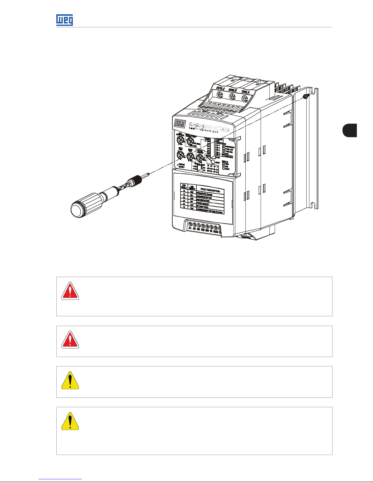
3.1.3.2 Mounting on Surface
Figure 3.3 shows the installation of the Soft-Starter SSW-08 on the surface of a mounting plate.
Figure 3.3: Installation procedures of the Soft-Starter SSW-08 on a surface
3.2 ELECTRICAL INSTALLATION
DANGER!
The Soft-Starter SSW-08 cannot be used as an emergency stop device.
Always use an isolation contactor or a circuit breaker to disconnect the power supply
of the SSW-08.
DANGER!
Be sure that the AC input power is disconnected before making any terminal
connection.
ATTENTION!
The information below may be used as a guide to achieve a proper installation. Follow
also the applicable local standards for electrical installations.
ATTENTION!
If a power isolating contactor or circuit breaker with minimum voltage coil is not used
at the first power on, then power up the electronics first, adjust the trimpots that are
necessary to put the SSW-08 into operation and only after this energize the power
section.
3
Installation and Connection
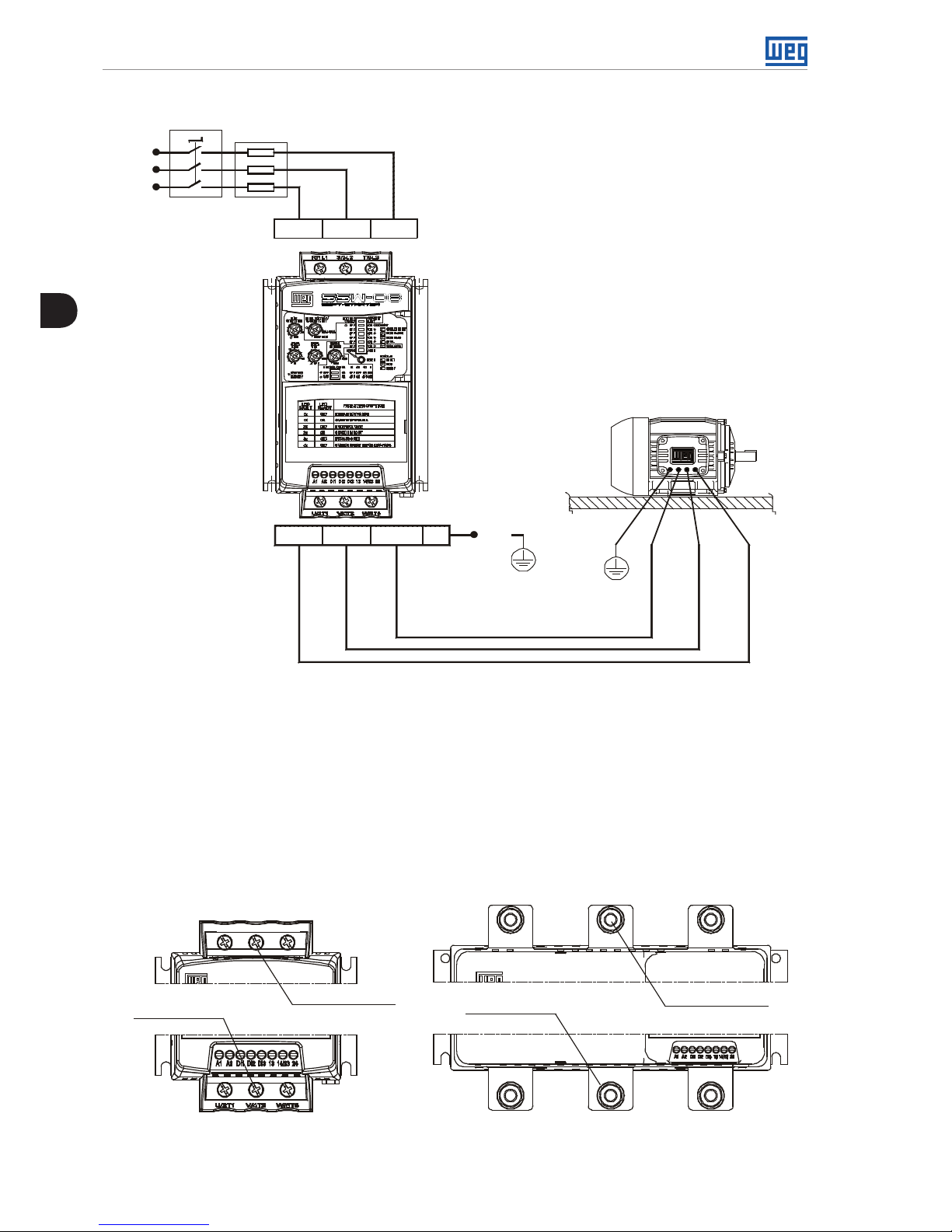
12 | SSW-08
Line
Circuit-breaker
Fuses
T
S
R
R/1L1 S/3L2 T/5L3
U/2T1 V/4T2 W/6T3 PE
PE
PE
Figure 3.4: Standard power/grounding connections
3.2.1 Power Terminals
The power connection terminals can be of different sizes and configurations depending on the
Soft-Starter SSW-08 model as shown in figures 3.5 and 3.6.
Terminals :
R / 1L1, S / 3L2 and T / 5L3: AC supply line.
U / 2T1, V / 4T2 and W / 6T3: Motor connection.
Output
Power Terminal
Input
Power Terminal
Output
Power Terminal
Input
Power Terminal
Models 17 A to 85 A
R/1L1 S/3L2 T/5L3
R/1L1 S/3L2
T/5L3
U/2T1
Models 130 A to 412 A
V/4T2
W/6T3
Figure 3.5: Power terminals
 Loading...