

WEG SSW-07 User Manual
Motors | Automation | Energy | Transmission & Distribution | Coatings
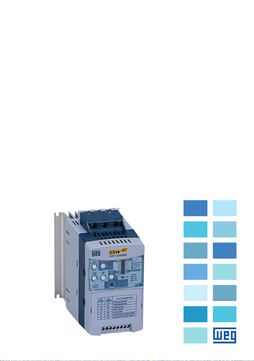
Soft-Starter
Arrancador Suave
Soft-Starter
SSW-07
User's Manual
Manual del Usuario
Manual do Usuário

SOFT-STARTER
USER’S MANUAL
MANUAL DEL
USUARIO DEL
ARRANCADOR
SUAVE
English
Español
MANUAL DO
USUÁRIO DA
SOFT-STARTER
Series: SSW-07
Document: 0899.5832 / 14
English - Español - Português
Português
04/2019
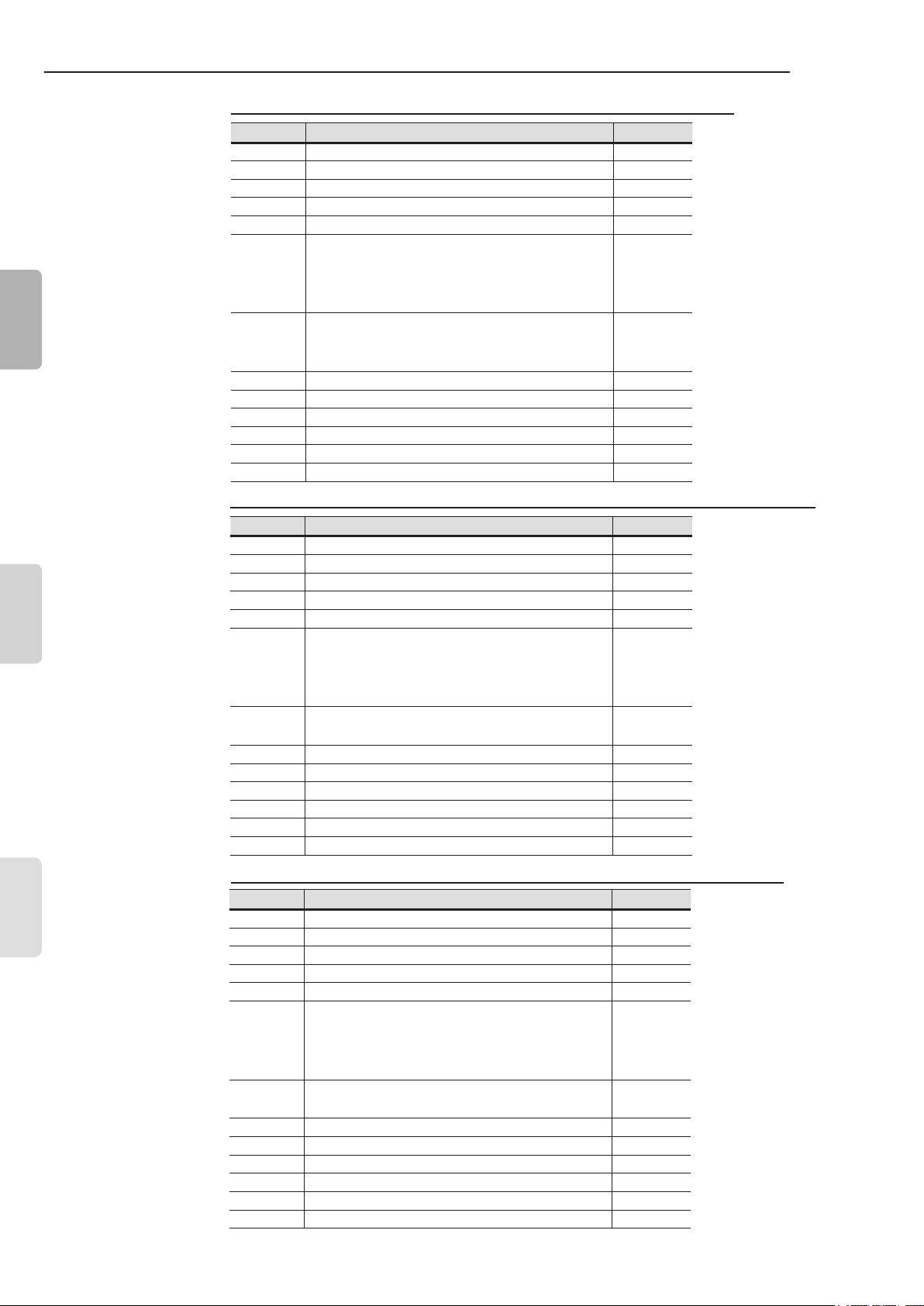
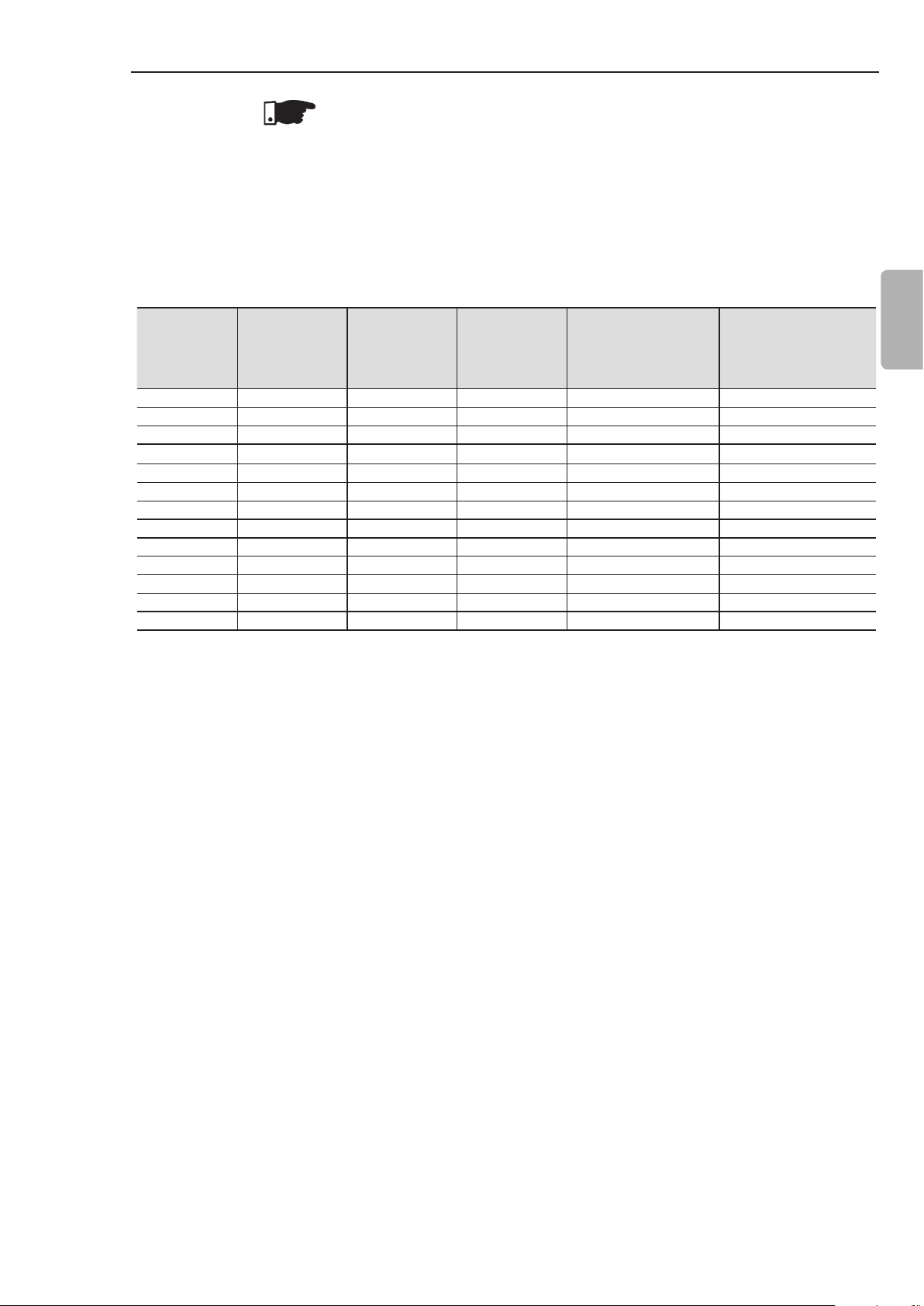
Summary of revisions / Sumario de las revisiones / Sumário das revisões
The information below describes the revisions in this manual.
Revision Description Chapter
1 First Edition 2 General Revision 3 General Revision 4 Size 4 Included -
5 and 6 Table 3.1 and 8.2 corrected 3 and 8
Revision after the Size 4 UL certication.
Changed: item 3.2.3; 3.2.4.1; 3.2.4.2; 3.2.7;
7
4.8; 5.2; E77 in the table 6.1; table 8.1
3, 4, 5, 6
and 8
English
Español
8
9 General Revision 10 Change in table 7.1 7
11 General Revision 12 General Revision 13 E19 Included in the table 6.1 6
14 Changes in item 3.2.4 3
Included new functions of
software version V1.4x
3,4
and 5
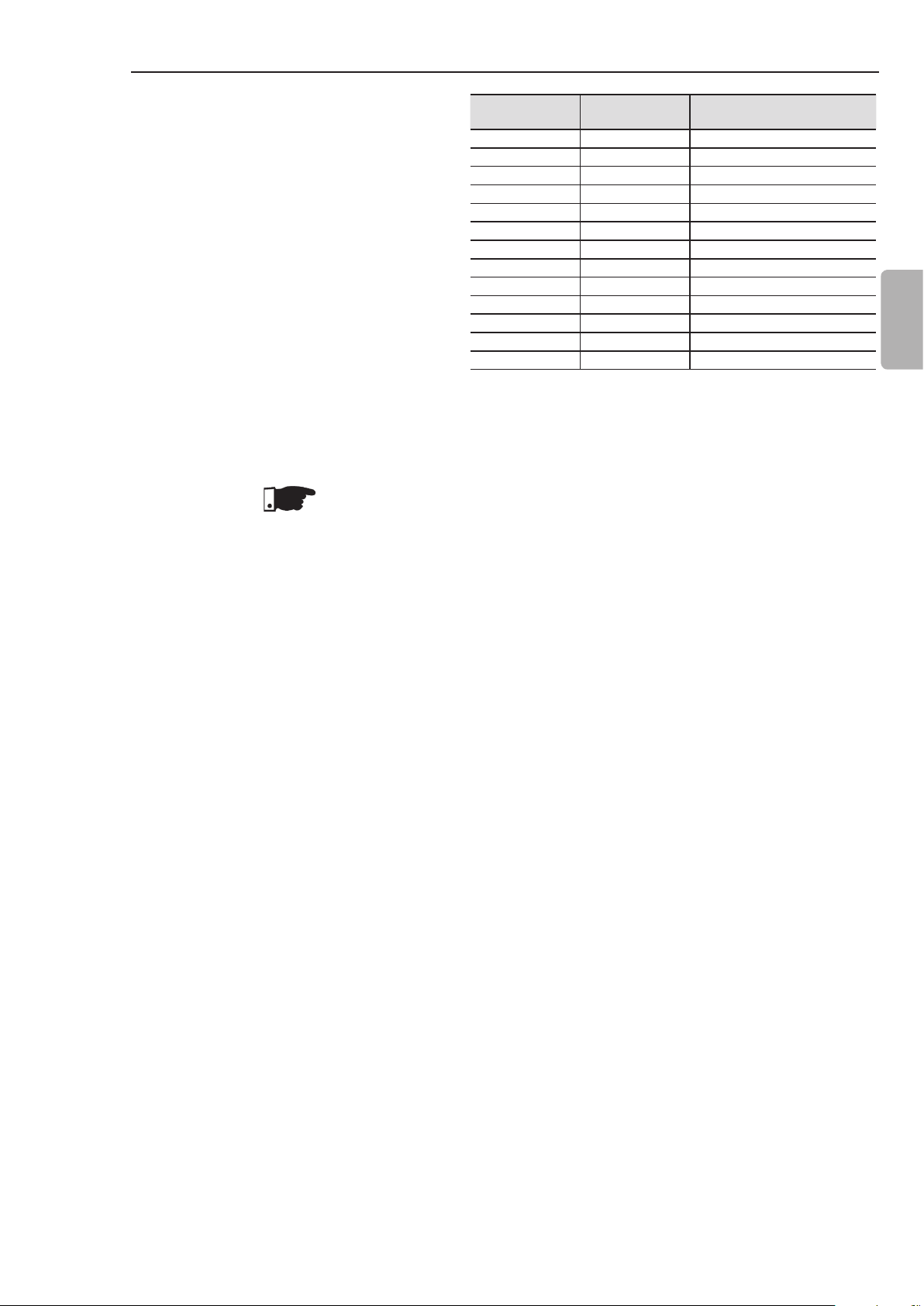
La información abajo describe las revisiones ocurridas en este manual.
Revisión Descripción Capítulo
1 Primer Edición -
2 Revisión General -
3 Revisión General -
4 Inclusión Mecánica 4 -
5 y 6 Correción de las tablas 3.1 y 8.2 3 y 8
Corrección luego de la certicación UL de la
Mecánica 4. Modicado: ítem 3.2.3; 3.2.4.1;
7
8
9 Revisión General 10 Alteración en la tabla 7.1 7
11 Revisión General 12 Revisión General 13 Inclusión E19 en la tabla 6.1 6
14 Modicaciones en el ítem 3.2.4 3
3.2.4.2; 3.2.7; 4.8; 5.2; E77 en la tabla 6.1;
tabla 8.1
Inclusión de las nuevas funciones de la
version de software V1.4x
3, 4, 5, 6
y 8
3, 4 y 5
Português
A informação abaixo descreve as revisões ocorridas neste manual.
Revisão Descrição Capítulo
1 Primeira Edição 2 Revisão Geral 3 Revisão Geral 4 Inclusão da mecânica 4 -
5 e 6 Correções das tabelas 3.1 e 8.2 3 e 8
Correção depois da certicação UL da
7
8
9 Revisão Geral 10 Alteração na tabela 7.1 7
11 Revisão Geral 12 Revisão Geral 13 Inclusão de E19 na tabela 6.1 6
14 Alterações no item 3.2.4 3
Mecânica 4. Alterado: item 3.2.3; 3.2.4.1;
3.2.4.2; 3.2.7; 4.8; 5.2; E77 na tabela 6.1;
tabela 8.1
Inclusão das novas funções da versão
de software V1.4x
3, 4, 5,
6 e 8
3, 4 e 5

Summary
CHAPTER 1
Safety Instructions
1.1 Safety Notices in the Manual ................................................5
1.2 Safety Notices on the Product ..............................................5
1.3 Preliminary Recommendations .............................................5
CHAPTER 2
General Information
2.1 About this Manual ................................................................7
2.2 About the Soft-Starter SSW-07 ............................................7
2.3 Soft-Starter SSW-07 Identication Plate ............................8
2.4 Receiving and Storage .......................................................11
CHAPTER 3
Installation and Connection
3.1 Mechanical Installation .......................................................12
3.1.1 Environmental Conditions ............................................12
3.1.2 Soft-Starter SSW-07 Dimensions ................................12
3.1.3 Mounting Specications ...............................................13
3.1.3.1 Mounting Inside a Panel .....................................14
3.1.3.2 Mounting on Surface ..........................................15
3.2 Electrical Installation ...........................................................15
3.2.1 Power Terminals ...........................................................16
3.2.2 Location of the Grounding, Control and Power
Connections ..................................................................17
3.2.3 Recommended Power and Grounding Cables ............18
3.2.4 Power Supply Connection to the Soft-Starter SSW-07 18
3.2.4.1 Short Circuit Capacity, Fuses, ................................
Circuit Breaker – UL ............................................19
3.2.4.2 Input Circuit Breakers and Fuses – IEC ..............20
3.2.4.3 Control Fuse ........................................................21
3.2.5 Soft-Starter SSW-07 Connection to the Motor .............22
3.2.5.1 Standard Three-Wire Connection .......................23
3.2.6 Grounding Connections ...............................................23
3.2.7 Control and Signal Connections ...................................24
3.3 Recommended Set-ups ......................................................25
3.3.1 Recommended Set-up with Command via Two-wire
Digital Inputs and Isolation Contactor ..........................26
3.3.2 Recommended Set-up with Command via Three-wire
Digital Inputs and Circuit-Breaker ................................26
3.3.3 Recommended Set-up with Command via Two-wire
Digital Inputs and Direction of Rotation .......................27
3.3.4 Recommended Set-up with Command via Two-wires
Digital Inputs and DC-Braking .....................................28
3.3.5 Symbols .......................................................................29
English

Summary
English
CHAPTER 4
Setting the SSW-07
4.1 Control Type Setting ...........................................................30
4.2 Kick Start ............................................................................31
4.3 Initial Voltage Setting ..........................................................31
4.4 Current Limit Setting ...........................................................32
4.5 Acceleration Ramp Time Setting ........................................31
4.6 Deceleration Ramp Time Setting ........................................31
4.7 Motor Current Setting .........................................................32
4.8 Motor Electronic Overload Protection ................................33
4.9 Reset ..................................................................................36
4.10 DI2 Digital Input Setting ....................................................36
4.11 Output Relay Operation ....................................................37
4.12 Relay Output RL1 Programming ......................................37
CHAPTER 5
Programming Information and Suggestions
5.1 Applications and Programming ...........................................38
5.1.1 Voltage Ramp Starting .................................................39
5.1.2 Current Limit Starting ...................................................40
5.1.3 Starting with Pump Control (P202 = 2) ........................40
5.1.4 Programming the control type in pump control ............42
5.2 Protections and Programming ............................................43
5.2.1 Suggestion on How to Program the Thermal Class .....43
5.2.2 Service Factor ..............................................................45
CHAPTER 6
Solution and Troubleshooting
6.1 Faults and Possible Causes ...............................................49
6.2 Troubleshooting ..................................................................52
6.3 Preventive Maintenance .....................................................53
CHAPTER 7
Options and Accessories
7.1 IP20 Kit ...............................................................................54
CHAPTER 8
Technical Characteristics
8.1 Nominal Powers and Currents According to UL508 ...........55
8.2 Nominal Powers and Currents for Standard IP55,
IV Pole Weg Motor .............................................................55
8.3 Power Data .........................................................................56
8.4 Electronics and Programming Data ....................................56
CHAPTER 1
SAFETY INSTRUCTIONS
This Manual contains the necessary information for the correct use
of the Soft-Starter SSW-07.
It was written to be used by qualied personnel with suitable training
or technical qualications to operate this type of equipment.
1.1 SAFETY NOTICES IN THE MANUAL
1.2 SAFETY NOTICES ON THE PRODUCT
The following safety notices will be used in the text.
DANGER!
The nonobservance of the procedures recommended in this warning
can lead to death, serious injuries and considerable material damage.
ATTENTION!
Failure to observe the recommended procedures in this notice may
lead to material damage.
NOTE!
The text intents to supply important information for the correct
understanding and good operation of the product.
The following symbols may be attached to the product as a safety
notice.
English
1.3 PRELIMINARY RECOMMENDATIONS
High Voltages.
Components are sensitive to electrostatic discharge.
Do not touch them.
Mandatory connection to ground protection (PE).
DANGER!
Only personnel with suitable qualication and familiar with the
Soft-Starter SSW-07 and associated equipment should plan or
implement the installation, start-up, operation and maintenance of
this equipment.
These personnel must follow all safety instructions in this manual
and/ or dened by local regulations.
Failure to follow these safety instructions may result in personnel
injury and/or equipment damage.
5
CHAPTER 1 - SAFETY INSTRUCTIONS
NOTE!
In this Manual, qualied personnel are those trained to:
1. Install, ground, power-up, and operate the Soft-Starter SSW-07
according to this manual and the required safety procedures;
2. Use protection equipment according to established regulations;
3. Give First Aid.
DANGER!
Always disconnect the general power supply before touching any
electrical component associated to the Soft-Starter SSW-07.
English
High voltage may be present even after the power supply is
disconnected. Wait at least 3 minutes for the total discharge of the
capacitors.
Always connect the equipment’s heatsink to the protection ground
(PE), at the proper connection point.
ATTENTION!
All electronic boards have components that are sensitive to
electrostatic discharges. Do not touch these components or
connectors directly.
If necessary, rst touch the grounded metallic heatsink or use a
suitable grounded wrist strap.
Do not apply any high voltage test on the Soft-Starter SSW-07!
If necessary, contact the manufacturer.
NOTE!
Soft-Starters SSW-07 may interfere with other electronic equipment.
Follow the measures in Chapter 3 to reduce these eects.
NOTE!
Read this manual completely before installing or operating the
Soft-Starter SSW-07.
NOTE!
For using this product in elevator applications be aware that it meets
elevator duty only in the USA market.
ATTENTION!
When in operation, electric energy systems – such as transformers,
converters, motors and cables – generate electromagnetic elds
(EMF), posing a risk to people with pacemakers or implants who
stay in close proximity to them. Therefore, those people must stay
at least 2 meters away from such equipment.
6
GENERAL INFORMATION
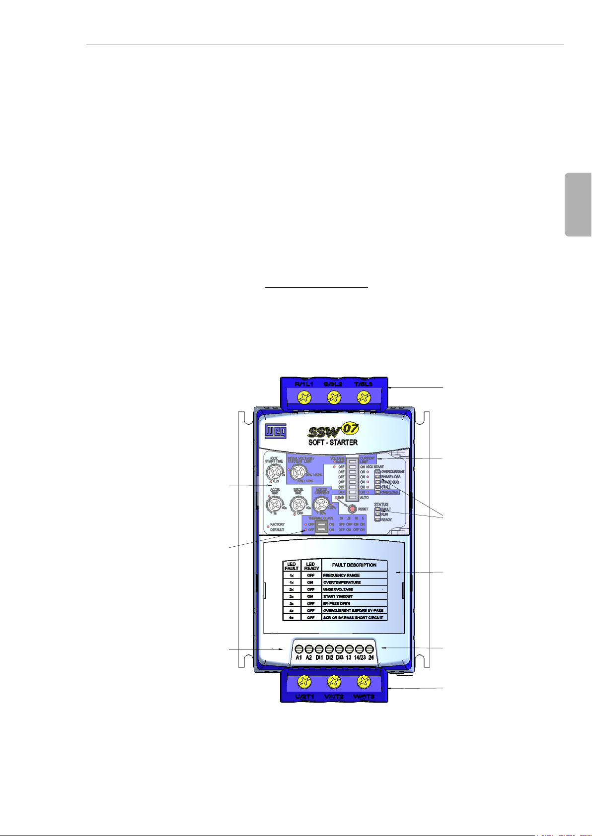
Tampa para
Trifásica
Opcionais Plug-In
Ajustes e Habilitar as
Proteções
DIP Swith para
LED's para Indicação
Entrada de Alimentação
de Status da SSW-07
Saída para Motor
Saida a Relé
(13,14/23 e 24)
CHAPTER 2
2.1 ABOUT THIS MANUAL
2.2 ABOUT THE
SOFT-STARTER
SSW-07
This manual presents the Soft-Starter installation, how to start it up,
its main technical characteristics and how to identify and correct the
most common problems. The manuals listed next must be consulted
in order to get more information regarding the functions, accessories
and working conditions:
Programming Manual, with a detailed description of the
parameters and its functions;
RS232 / RS485 Communication Manual.
DeviceNet Communication Manual.
These manuals are supplied in electronic format on the CD-ROM
that accompanies the Soft-Starter, or can be obtained at WEG’s
web site: http://www.weg.net.
The Soft-Starter SSW-07 is a high performance product that permits
the start control of the three phase AC induction motors. Thus, it
prevents mechanical shocks on the load and current peaks in the
supply line.
Three-phase
Power Supply
English
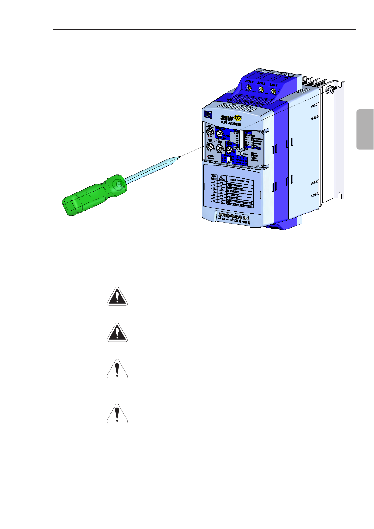
Trimpots to adjust
DIP switch to adjust
the Thermal Class
Electronic Power Supply
(A1 and A2)/
Start/Stop Command
of the Motor (D1) and
Reset (DI2 and DI3)
Figure 2.1 - Frontal view of the SSW-07
DIP Switch for
Soft-Starter adjustment
and protection enabling
Status Indication LEDs
of the SSW-07
Lid for optional Plug-in
Modules
Relay Output
(13, 14/23 and 24)
Motor Output
7
CHAPTER 2 - GENERAL INFORMATION
English
Three-Phase
Power Supply
R S
U
V W
Three-Phase Motor
Programmable
Digital Inputs
Dl1
Dl2
Dl3
T
Control
Power Supply
A1
A2
3 x
Digital Signal
2 x
Processor
DSP
PE
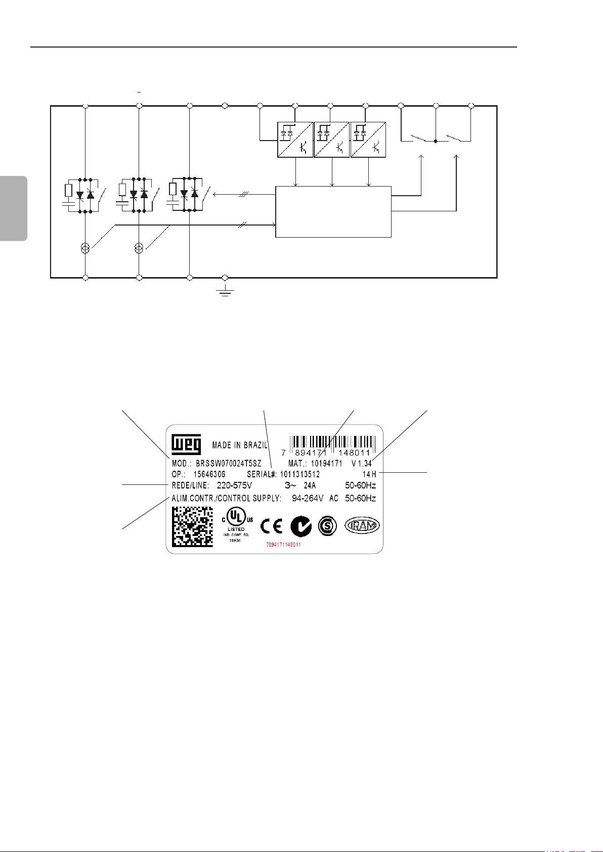
Figure 2.2 - Soft-Starter SSW-07 block diagram
Programmable Digital
Outputs
13
14/23 24
RL1
RL2
2.3 SOFT-STARTER SSW-07 IDENTIFICATION PLATE
WEG Stock
SSW-07 Model
Input Data (Voltage,
Number of Phases,
Current and Frequency)
Control Power Supply
Data (Voltage, Frequency)
Serial Number
Figure 2.3 - Soft-Starter SSW-07 identication plate
Item Number
Software
Version
Manufacturing date
(14 corresponds to
week and H to year)
8
CHAPTER 2 - GENERAL INFORMATION
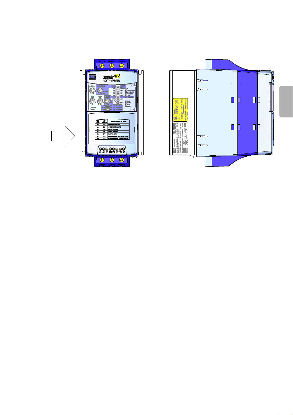
VISTA FRONTAL
VISTA DE X
Position of the Identication Plate on the Soft-Starter SSW-07:
FRONTAL VIEW X VIEW
English
X
Figure 2.4 - Location of the labels
9
CHAPTER 2 - GENERAL INFORMATION
End of
Code
Special
Software
Blank =
Standard
S1 = Special
Software
English
Special
Hardware
Blank =
Degree of
Protection
Blank =
S = Standard
O = with
220-575 Vac Optional:
(2)
Standard
H1 = Electronics
supply: 110 to
130 Vac
H2 = Electronics
(1)
Standard
IP=IP20
Optional
(2)
supply: 208 to
240 Vac
10
HOW TO SPECIFY THE SSW-07 MODEL:
Three-
Phase
SSW-07
Nominal Current
WEG Soft-
Starter
EX SSW-07 0017 T 5 S _ _ _ _ _ _ Z
Market
Power
Supply
0017 = 17 A
0024 = 24 A
0030 = 30 A
Series
SSW-07
BR = Brazil
EX = Export
0045 = 45 A
0061 = 61 A
0085 = 85 A
0130 = 130 A
0171 = 171 A
0200 = 200 A
0255 = 255 A
0312 = 312 A
0365 = 365 A
0412 = 412 A
(1) Only for models 130 A to 412 A.
(2) Only for the 255 A to 412 A models.
NOTE!
The option eld (S or O) denes if the Soft-Starter SSW-07 will be a standard version or if it will include any optional. If standard, the
code ends here.
Always put the letter Z at the end. For example:
EXSSW070017T5SZ = Standard Soft-Starter SSW-07 with 17 A and 220 V to 575 V to three-phase input with the User’s Guide in
English, Spanish and Portuguese.
If there is any optional, the elds must be lled out in the correct sequence until the code is completed with the letter Z.
The standard product as dened by this code is described as:
Degree of Protection: IP20 from 17 A to 85 A and IP00 from 130 A to 412 A.
CHAPTER 2 - GENERAL INFORMATION
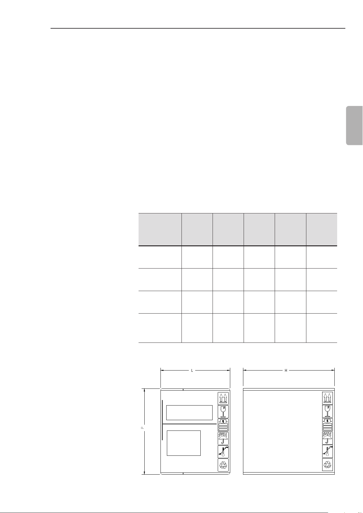
2.4 RECEIVING AND STORAGE
The Soft-Starter SSW-07 is supplied in a cardboard box. On the
outside of the package there is an identication plate which is
identical to the one placed on the Soft-Starter SSW-07.
To open the package:
1- Put it on a table;
2- Open the package;
3- Take out the Soft-Starter.
Check if:
The Identication plate of the Soft-Starter SSW-07 matches the
model purchased:
Damage has occurred during transport. If so, contact the carrier
immediately.
If the Soft-Starter SSW-07 is not installed immediately, store it in
its package in a clean and dry place with temperature between
-25 °C (-13 °F) and 65 °C (149 °F). 1 hour at -40 °C (-40 °F) is
permitted.
English
SSW-07
Model
17 A
24 A
30 A
45 A
61 A
85 A
130 A
171 A
200 A
255 A
312 A
365 A
412 A
Height
H
mm
(in)
221
(8.70)
260
(10.24)
356
(14.02)
415
(16.34)
Table 2.1 - Dimensions of the package in mm (in)
Width
L
mm
(in)
180
(7.09)
198
(7.80)
273
(10.75)
265
(10.43)
Depth
P
mm
(in)
145
(5.71)
245
(9.65)
295
(11.61)
320
(12.6)
Volume
3
cm
(in3)
5768
(352.2)
12613
(770.8)
28670
(1750)
35192
(2147)
Weight
kg
(lb)
1.65
(3.64)
3.82
(8.42)
8.36
(18.43)
12.8
(28.2)
Figure 2.5 - Dimensions of the package
11
C
A
B
P
L
3.1 MECHANICAL INSTALLATION
CHAPTER 3
INSTALLATION AND CONNECTION
This chapter describes the procedures for the electrical and
mechanical installation of the Soft-Starter SSW-07. The guidelines
and suggestions must be followed for the correct operation of the
Soft-Starter SSW-07.
3.1.1 Environmental
English
Conditions
The location of the Soft-Starters SSW-07 is an important factor to
assure the correct operation and high product reliability.
Avoid:
Direct exposure to sunlight, rain, high moisture and sea air ;
Exposure to explosive or corrosive gases and liquids;
Exposure to excessive vibration, dust or any metallic and/or oil
particles in the air.
Allowed Environmental Conditions:
Surrounding air Temperature: 0 ºC to 55 ºC (32 ºF to 131 ºF) -
nominal conditions.
Relative air moisture: 5 % to 90 %, with no-condensation.
Maximum altitude: 1,000 m (3,300 ft) above sea level - nominal
conditions.
From, 1,000 m to 4,000 m (3,300 ft to 13,200 ft) above sea level -
current reduction of 1 % for each 100 m (330 ft) above 1,000 m
(3,300 ft).
From 2000 m to 4000 m (6,600 ft to 13,200 ft) above sea level -
voltage reduction of 1.1 % for each 100m (330 ft) above 2,000 m
(6,600 ft).
Pollution degree: 2 (according to the UL508).
Normally, only non conductive pollution. Condensation must not
cause conduction in the particles in the air.
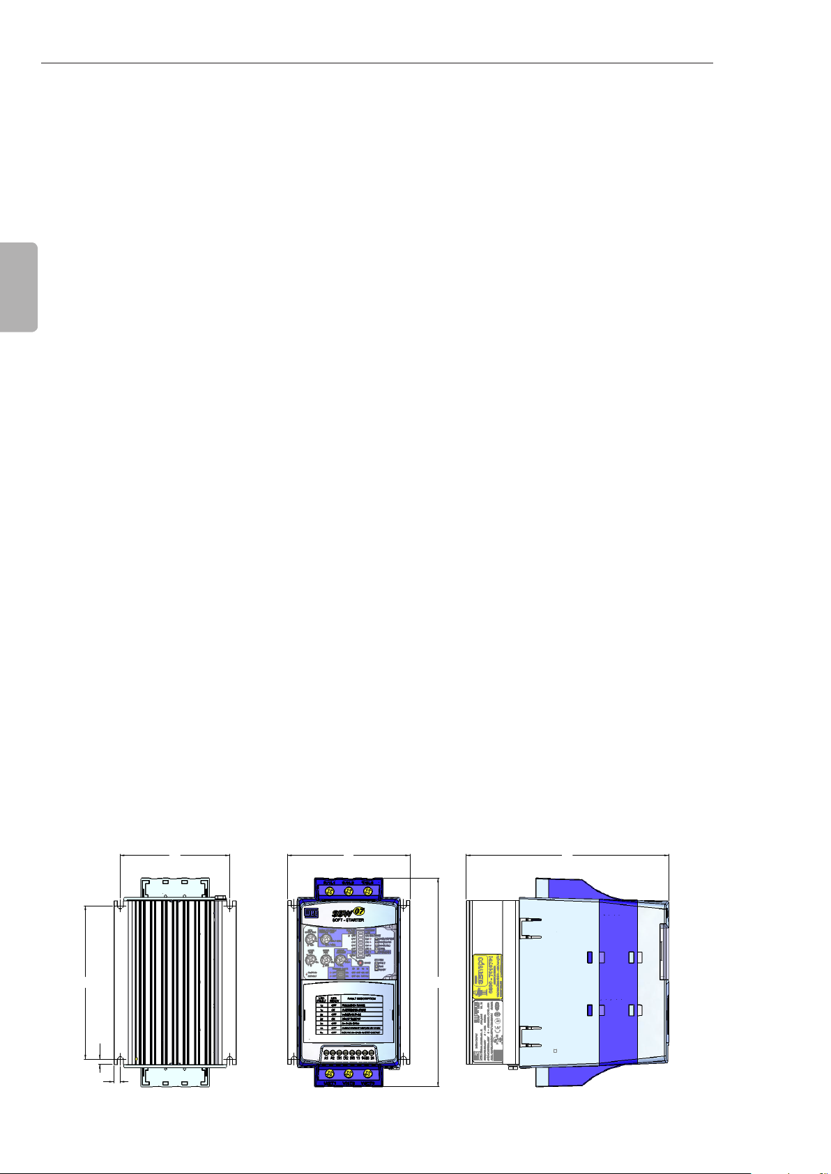
3.1.2 Soft-Starter SSW-07 Dimensions
B
D
D
C
12
The external dimensions and mounting holes are shown in gure
3.1 and table 3.1 below.
A
Figure 3.1 - SSW-07 dimensions
L
H
H
P
CHAPTER 3 - INSTALLATION AND CONNECTION
Height
SSW-07
Model
17 A
24 A
30 A
45 A
61 A
85 A
130 A
171 A
200 A
255 A
312 A
365 A
412 A
H
mm
(in)
162
(6.38)95(3.74)
208
(8.19)
276
(10.9)
331
(13.0)
* IP20 with optional.
3.1.3 Mounting
Specications
Width
L
mm
(in)
144
(5.67)
223
(8.78)
227
(8.94)
Depth
P
mm
(in)
157
(6.18)85(3.35)
203
(7.99)
220
(8.66)
242
(9.53)
A
mm
(in)
132
(5.2)
208
(8.19)
200
(7.87)
B
mm
(in)
120
(4.72)5(0.20)4(0.16) M4
148
(5.83)6(0.24)
210
(8.27)
280
(11.0)15(0.59)9(0.35)
C
mm
(in)
7.5
(0.3)
D
Mounting
mm
(in)
3.4
(0.13) M4
5
(0.2) M5
Screw
M8
Weight
kg
(lb)
1.3
(2.9) IP20
3.3
(7.28) IP20
7.6
(16.8)
11.5
(25.4)
Table 3.1 - Installation data with dimensions in mm (in)
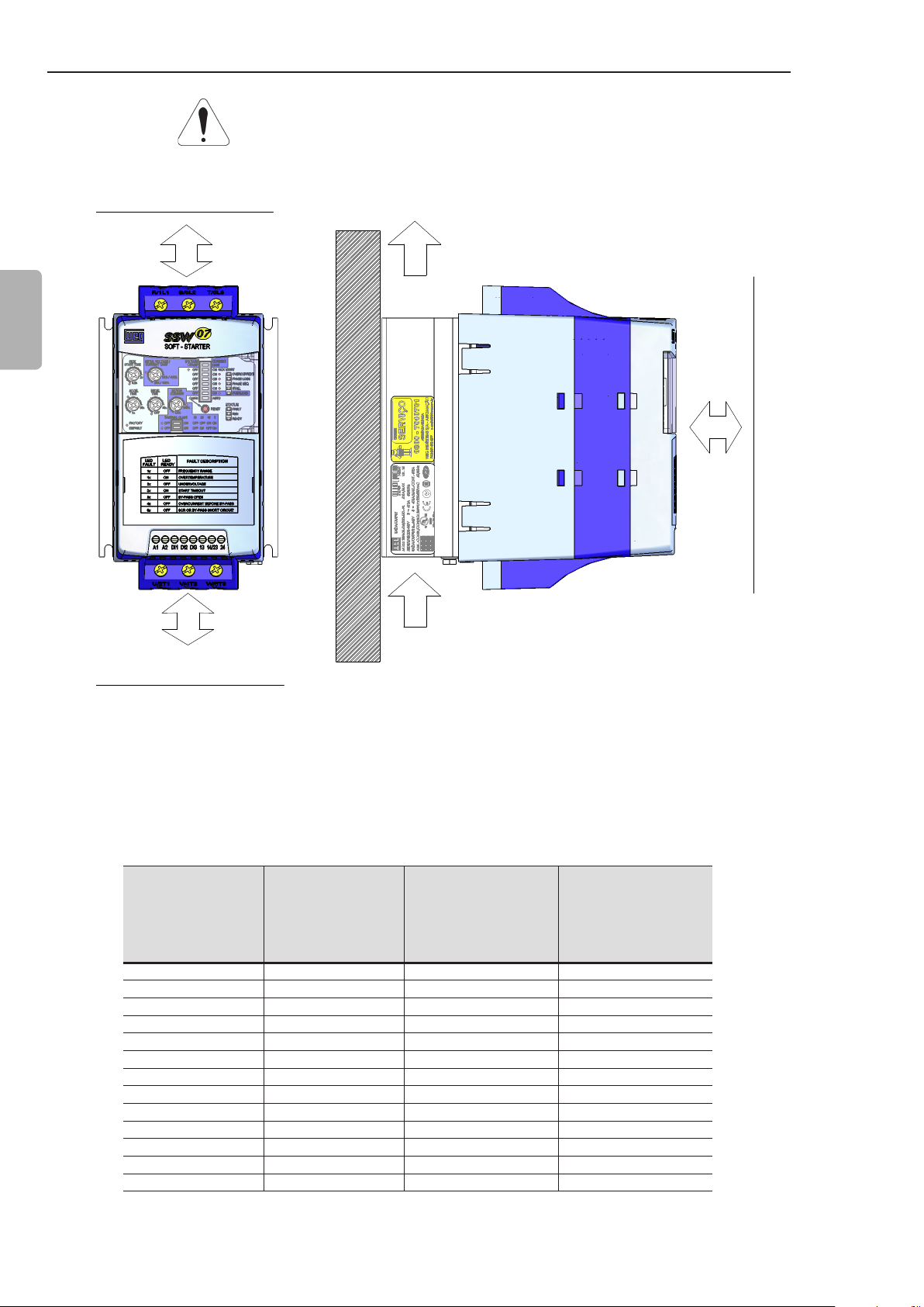
To install the Soft-Starter SSW-07 leave at least the free spaces
surrounding the Soft-Starter as in gure 3.2 below. The dimensions
of these free spaces are described in table 3.2.
Degree
of
Protection
IP00 *
English
IP00 *
SSW-07 Model
17 A
24 A
30 A
45 A
61 A
85 A
130 A
171 A
200 A
A
mm
(in)
50
(2)
80
(3.2)
100
(4)
B
mm
(in)
50
(2)
80
(3.2)
100
(4)
C
mm
(in)
30
(1.2)
30
(1.2)
30
(1.2)
255 A
312 A
365 A
150
(6)
150
(6)
30
(1.2)
412 A
Table 3.2 - Recommended free spaces
Install the Soft-Starter SSW-07 in the vertical position according to
the following recommendations:
1) Install on a reasonably at surface;
2) Do not put heat sensitive components immediately above the
Soft-Starter SSW-07.
ATTENTION!
If a Soft-Starter SSW-07 is installed on top of another use the
minimum distance A + B and diverge from the top Soft-Starter the
hot air that comes from the one beneath it.
13
CHAPTER 3 - INSTALLATION AND CONNECTION
ATTENTION!
Independent conduits or cable trays must be planned for physic
separation of signal, control and power cables. (Refer to item 3.2
Electrical Installation).
A
A
English
SAIDA
Air Flow
FLUXO DE AR
Outlet
C
C
3.1.3.1 Mounting Inside a Panel
SSW-07
Model
130 A 12 117 129
171 A 12 154 166
200 A 12 180 192
255 A 12 230 242
312 A 12 281 293
365 A 12 329 341
412 A 12 371 383
Air Flow
B
B
Figure 3.2 - Free spaces for ventilation
ENTRADA
FLUXO DE AR
Inlet
For Soft-Starters SSW-07 installed in panels or closed metallic
boxes exhaustion/cooling is required so the temperature does not
exceed the maximum allowed. Refer to dissipated nominal power
in table 3.3.
Average Power
Dissipated Power
in the electronics
(W)
17 A 12 15.3 27.3
24 A 12 21.6 33.6
30 A 12 27 39
45 A 12 41 53
61 A 12 55 67
85 A 12 77 89
dissipated
10 starts/h
3 x In @ 30 s
(W)
Total Average Power
dissipated
10 starts/h
3 x In @ 30 s
(W)
14
Table 3.3 - Dissipated power for ventilator panel dimensioning
CHAPTER 3 - INSTALLATION AND CONNECTION
3.1.3.2 Mounting on Surface
Figure 3.3 shows the installation of the Soft-Starter SSW-07 on the
surface of a mounting plate.
English
Figure 3.3 - Installation procedures of the Soft-Starter SSW-07 on a surface
3.2 ELECTRICAL
INSTALLATION
DANGER!
The Soft-Starter SSW-07 cannot be used as an emergency stop
device.
DANGER!
Be sure that the AC input power is disconnected before making any
terminal connection.
ATTENTION!
The information below may be used as a guide to achieve a proper
installation. Follow also the applicable local standards for electrical
installations.
ATTENTION!
If a power isolating contactor or circuit breaker with minimum voltage
coil is not used at the rst power on, then power up the electronics
rst, adjust the trimpots that are necessary to put the SSW-07 into
operation and only after this energize the power section.
15
CHAPTER 3 - INSTALLATION AND CONNECTION
Circuit-breaker
R
S
T
Line
English
Fuses
R/1L1 S/3L2 T/5L3
3.2.1 Power Terminals
U/2T1 V/4T2 W/6T3 PE
Figure 3.4 - Standard power/grounding connections
PE
PE
The power terminal blocks vary in size and conguration, depending
on the SSW-07 soft-starter model, as can be observed at the gures
3.5 and 3.6.
Terminals:
R / 1L1, S / 3L2 and T / 5L3: AC supply line.
U / 2T1, V / 4T2 and W / 6T3: Motor connection.
16
CHAPTER 3 - INSTALLATION AND CONNECTION
R/1L1 S/3L2 T/5L3
Output Power
BORNE DE SAIDA
POTENCIA
Terminal
Models 17 A to 85 A Models 130 A to 412 A
Input
BORNE DE ENTRADA
Power Terminal
POTENCIA
SSW-07
Model
17 A
24 A
30 A
45 A
61 A
85 A
130 A
171 A
200 A
255 A
312 A
365 A
412 A
Figure 3.5 - Power terminals
Enclosure
Size
Screw/
Terminal
Size 01 Terminal
Size 02 Terminal
Size 03
Size 04
M8
(5/16”)
M10
(3/8”)
R/1L1
Output
BORNE DE SAIDA
POTENCIA
Power Terminal
U/2T1
S/3L2
V/4T2
Input
BORNE DE ENTRADA
POTENCIA
Power Terminal
Line / Motor Grounding
Torque
Nm
Screw
(in lb)
3
(27)
5.5
(49)
19
(168)
37
(328)
M4
(5/32”)
M5
(3/16”)
M6
(1/4”)
Terminal
T/5L3
W/6T3
English
Torque
Nm
(in lb)
4.5
(40)
6
(53)
8.3
(73)
0.5
(4.5)
Table 3.4 - Maximum torque for power connection
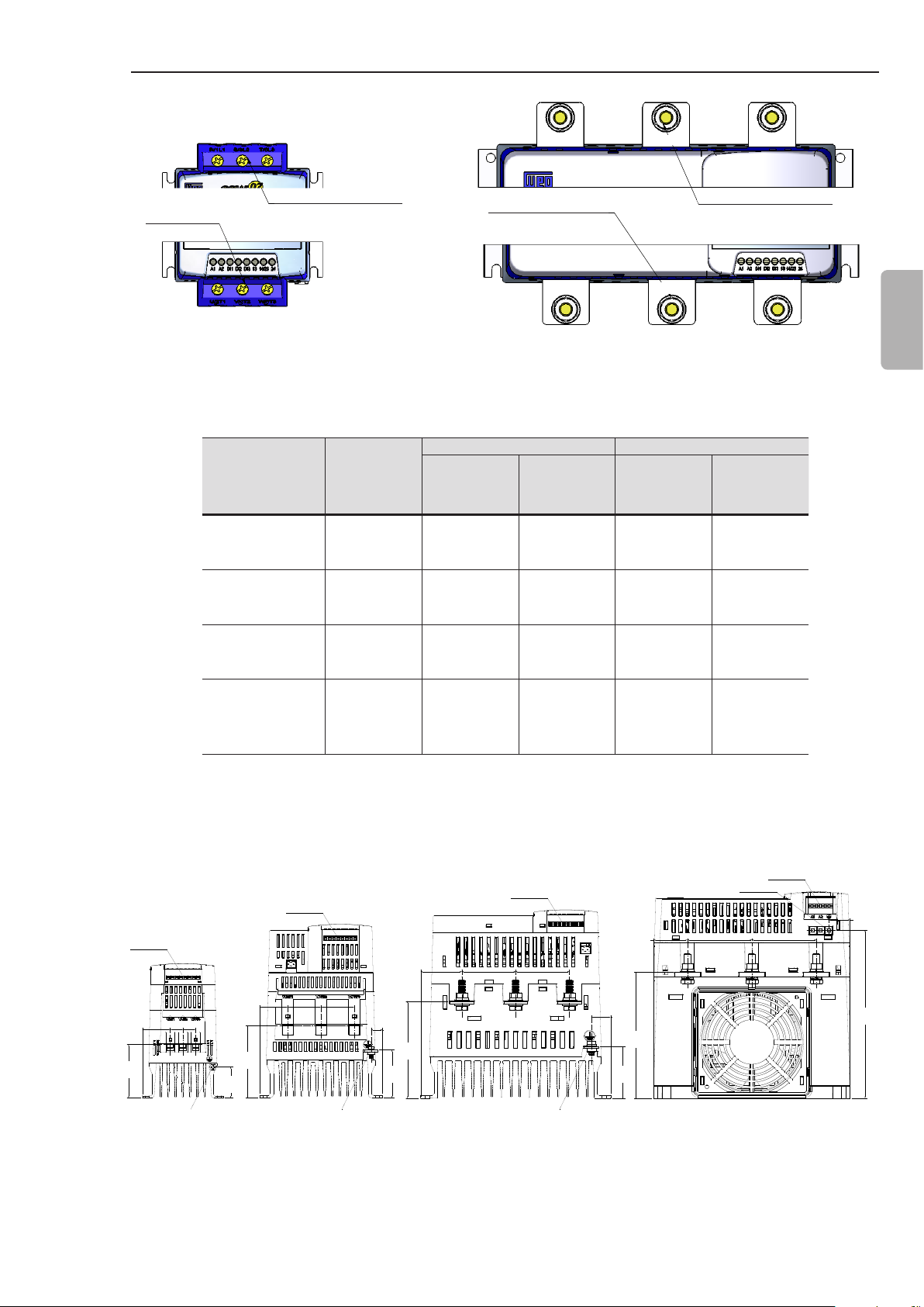
3.2.2 Location of the Grounding, Control and Power Connections
Control
Control
CO NTR OLE
Control
CO NTR OLE
48.2
(1.90)
39.0
(1.54)
ATERRAM EN TO
39.0
(1.54)
13.3
(0.52)
114
(4.48)
56.3
(2.22)
62.8
(2.48)
32.7
(1.29)
ATERRAM EN TO
33.0
36.3
84,8
(3.34)
(1.30)
14.8
14.8
(0.59)
(0.59)
(1.43)
Grounding Grounding Grounding
Dimensions in mm (in).
Figure 3.6 - Location of the grounding, control and power connections
CO NTR OLE
63.0
(2.48)
(2.48)
ATERRAM EN TO
63.0
22.7
(0.89)
60.5
(2.38)
39.7
(1.56)
148
(5.81)
Grounding
ATERRAM EN TO
75.5
(2.97)
Control
CO NTR OLE
75.5
(2.97)
25.1
(0.99)
197
(7.75)
17
CHAPTER 3 - INSTALLATION AND CONNECTION
3.2.3 Recommended Power and Grounding Cables
English
The described specications in table 3.5 are valid only for the
following conditions:
Copper wires for 70 ºC (158 ºF) with PVC insulation for ambient
temperature of 40 ºC (104 ºF), installed in perforated and not
agglomerated conduits.
Naked or silver coated copper busbars with round edges with 1
mm radius with ambient temperature of 40 ºC (104 ºF) and bus
temperature of 80 °C (176 °F).
NOTE!
For correct cable dimensioning, consider the installation condition
and the maximum permitted line voltage drop.
SSW-07
Model
17 A 4 12 4 12
24 A 6 10 6 10
30 A 6 10 6 10
45 A 10 8 6 10
61 A 16 6 10 8
85 A 25 4 10 8
130 A 50 1 25 4
171 A 70 2/0 35 2
200 A 95 3/0 50 1
255 A 120 250 kcmil 2.5 14
312 A 185 350 kcmil 2.5 14
365 A 240 500 kcmil 2.5 14
412 A 300 600 kcmil 2.5 14
Power Cable Grounding Cable
(mm2) AWG (mm2) AWG
3.2.4 Power Supply Connection to the Soft-Starter SSW-07
18
Table 3.5 - Minimum cable gauge specication
DANGER!
The AC input must be compatible with the voltage range of the
Soft-Starter SSW-07.
DANGER!
Provide a power supply disconnecting switch for the Soft-Starter
SSW-07. This disconnecting switch must disconnect the AC input
voltage to the Soft-Starter SSW-07 whenever necessary (for
example: during maintenance services).
If a disconnected switch or a contactor is inserted in the motor supply
line never operate these devices with the motor running or when
the Soft-Starter SSW-07 is enabled.
ATTENTION!
The overvoltage control in the line that feeds the soft-starter must
be done using overvoltage suppressors with a clamping voltage of
680 Vac (phase-to-phase connection) and an energy absorption
capability of 40 joules (17 A to 200 A models) and 80 joules (255 A
to 412 A models).
CHAPTER 3 - INSTALLATION AND CONNECTION
NOTE!
Use the wire sizes and fuses recommended in tables 3.5 and 3.7.
The connector tightening torque is indicated in table 3.4. Use only
copper wires 70 °C (158 °F).
3.2.4.1 Short Circuit Capacity, Fuses, Circuit Breaker – UL
SSW-07
Model
17 A 17 A 5 kA < 30A 6.6URD30TTF0050 170M2611
24 A 24 A 5 kA < 40A 6.6URD30TTF0080 170M1366
30 A 30 A 5 kA < 40A 6.6URD30TTF0080 170M1366
45 A 45 A 5 kA < 150A 6.6URD30TTF0100 170M1367
61 A 61 A 5 kA < 150A 6.6URD30TTF0125 170M1368
85 A 85 A 10 kA < 150A 6.6URD30TTF0200 170M1370
130 A 130 A 10 kA < 225A 6.6URD31TTF0325 170M1372
171 A 171 A 10 kA < 250A 6.6URD32TTF0450 170M3170
200 A 200 A 10 kA < 250A 6.6URD32TTF0500 170M3171
255 A 255 A 18 kA < 400A 6.6URD32TTF0400 170M5158
312 A 312 A 18 kA < 400A 6.6URD33TTF0500 170M3171
365 A 365 A 18 kA < 600A 6.6URD33TTF0550 170M5161
412 A 412 A 18 kA < 600A 6.6URD33TTF0700 170M6161
Nominal
Rating
Table 3.6 presents the short circuit capacity, Standard Fault, of
the power supply (symmetric Arms) at which the SSW-07 can be
installed, provided that protected by means of regular fuses or circuit
breakers, used in the UL tests.
Short Circuit
Rating
≤ 600V
Table 3.6 - Short circuit capacity – UL Standard Fault
Circuit Breaker
(CB) - UL489
Any MCCB
Ultra-fast Fuses
Ferraz Shawmut/
Mersen
Flush End Contacts
Ultra-fast Fuses
Cooper Bussmann
Bolted Contacts
English
The fuses in table 3.6 used in the SSW-07 UL tests are of the ultrafast (aR) type, which also reduce the risk of SCRs being burned by
over current transients.
Table 3.7, presents the short circuit capacity, High Fault, of the power
supply (symmetric Arms) at which the SSW-07 can be installed
within a closed panel, provided that protected by means of circuit
breakers, used in the UL tests.
19

CHAPTER 3 - INSTALLATION AND CONNECTION
SSW-07
Model
17 A 17 A 65 kA
24 A 24 A 65 kA WEG ACW125W-FTU30-3 18 kA
30 A 30 A 65 kA WEG ACW125W-FTU40-3 18 kA
Nominal
Rating
English
45 A 45 A 65 kA
61 A 61 A 65 kA
85 A 85 A 65 kA
130 A 130 A 65 kA
171 A 171 A 65 kA
200 A 200 A 65 kA
255 A 255 A 65 kA
312 A 312 A 65 kA
365 A 365 A 65 kA
412 A 382 A 65 kA
Short
Circuit
Rating
≤ 480V
Circuit Breaker
(DIVQ)
WEG ACW125W-FTU25-3 or
UBW225H-FTU30-3A or
HFD3030L
WEG ACW125W-FTU60-3
or UBW225H-FTU150-3A or
HFD3150L
WEG ACW125W-FTU60-3
or UBW225H-FTU150-3A or
HFD3150L
WEG ACW125W-FTU60-3
or UBW225H-FTU150-3A or
HFD3150L
WEG ACW250W-FTU250-3
or UBW225H-FTU225-3A or
HFD3225L
WEG ACW250W-FTU250-3 or
UBW250H-FTU250-3A
or HJD3250
WEG ACW250W-FTU250-3 or
UBW250H-FTU250-3A
or HJD3250
WEG ACW400W-FTU400-3
or UBW400H-FTU400-3A or
HKD3400
WEG ACW400W-FTU400-3
or UBW400H-FTU400-3A or
HKD3400
WEG ACW800W-FTU800-3 or
UBW600H-FTU600-3A
or HLD3600
WEG ACW800W-FTU800-3 or
UBW600H-FTU600-3A
or HLD3600
Short Circuit
Rating
≤ 600V
18 kA
18 kA
18 kA
18 kA
18 kA
30 kA
30 kA
30 kA
30 kA
42 kA
42 kA
Circuit Breaker
(DIVQ)
UBW225H-FTU40-
3A or HFD3040L
UBW225H-FTU40-
3A or HFD3040L
UBW225H-FTU40-
3A or HFD3040L
UBW225H-FTU40-
3A or HFD3040L
UBW225H-FTU150-
3A or HFD3150L
UBW225H-FTU150-
3A or HFD3150L
UBW225H-FTU150-
3A or HFD3150L
UBW225H-FTU225-
3A or HFD3225L
UBW250L-FTU250-
3A or JDC3250
UBW250L-FTU250-
3A or JDC3250
UBW400H-FTU400-
3A or HKD3400
UBW400H-FTU400-
3A or HKD3400
UBW600L-FTU600-
3A or LDC3600
Minimum
Enclosure
Dimensions
(WxHxL) (mm)
800 600 300
800 600 300
800 600 300
800 600 300
800 600 300
800 600 300
800 600 300
800 600 300
800 600 300
1000 600 400
1000 600 400
1000 600 400
1000 600 400
3.2.4.2 Input Circuit Breakers and Fuses – IEC
20
Table 3.7 - Short circuit capacity – UL High Fault
Ultra-fast fuses (aR), regular fuses or circuit breakers:
For Coordination Type 1, regular fuses or circuit breakers can be
used, according to IEC 60947-4-2, which will protect the installation
against short circuits, however, the SCRs will not be protected.
Circuit breakers of the table 3.6 and table 3.7.
For Coordination Type 2, the fuses to be used in the input must be
for protection of semiconductors, ultra-fast type (aR), according
to IEC 60947-4-2. They reduce the risk of the SCRs to burn out
because of overcurrent transients.
CHAPTER 3 - INSTALLATION AND CONNECTION
SSW-07
Model
17 A 720 FNH1-63-K-A
24 A 4000 FNH00-80-K-A
30 A 4000 FNH00-100-K-A
45 A 8000 FNH00-125-K-A
61 A 10500 FNH00-160-K-A
85 A 51200 FNH00-250-K-A
130 A 97000 FNH1-400-K-A
171 A 168000 FNH2-500-K-A
200 A 245000 FNH2-630-K-A
255 A 90000 FNH3-500-K-A
312 A 238000 FNH3-710-K-A
365 A 238000 FNH3-710-K-A
412 A 320000 2 x FNH3-500-K-A
Table 3.8 - I²t of the SCR and aR Weg fuses
I²t SCR
(A²s)
FNH aR
Blade Contacts
Ultra-fast fuses (aR), with l²t smaller than or equal to 75 % of the
value of the SCR indicated (A²s) in table 3.8.
NOTE!
The maximum I²t of the fuse of the SSWs varies according to the
design of the SCR used; therefore, higher rated currents may
present lower I²t.
English
3.2.4.3 Control Fuse
The fuse rated current should preferably be equal to or higher than
the motor starting current in order to prevent cyclic overloads and
the tripping of the fuse in the prohibited area of the Time x Current
curve.
The proper sizing of the fuse should take into account: the local
standards for electrical installations, the starting cycle, number
of starts per hour, starting current and starting time, ambient
temperature and altitude.
For the correct sizing of the fuses, see WEG Fuse Catalog:
www.weg.net
Automation - Fuses aR and gL/gG - Type NH Blade Contact, NH
Flush End and Diametral.
Annex 1: Sizing Criteria for Ultra-Fast Fuses aR Blade Contact and
Flush End.
Annex 2: Table for aR Fuse Sizing to Protect SSW Soft-Starters
and CFW Inverters.
For the electronic supply protection of the SSW-07 must be used
fuse type D, or circuit breaker type C:
Fuse 2 A Type D or Circuit breakers 2 A Type C.
21
CHAPTER 3 - INSTALLATION AND CONNECTION
3.2.5 Soft-Starter SSW-07 Connection to the Motor
DANGER!
Power factor correction capacitors must never be installed at the
output of the Soft-Starter SSW-07. (U / 2T1, V / 4T2 and W / 6T3).
English
ATTENTION!
To ensure that the protections based on the current reading and
display operate correctly, for example the overload, the motor
nominal current must not be lower than 50 % of the nominal SoftStarter SSW-07 current.
NOTE!
Use the wire sizes and fuses recommended in tables 3.5, 3.6 and
3.7. The connector tightening torque is indicated in table 3.4. Use
only copper wires.
NOTE!
The Soft-Starter SSW-07 is provided with electronic protection
against motor overload. This protection must be set according to
the specic motor. When several motors are connected to the same
Soft-Starter SSW-07 use individual overload relays for each motor.
Line current of the Soft-Starter SSW-07 is equal to the motor current.
22
CHAPTER 3 - INSTALLATION AND CONNECTION
3.2.5.1 Standard Three-Wire Connection
3.2.6 Grounding
Connections
R
S
T
N
PE
R
U
1/U1
S
V
4/U2
6/W2
3/W1
T
2/V1
5/V2
R
S
T
N
PE
R
W
U
1/U1
4/U2
S
2/V1
5/V2
6/W2
T
WV
3/W1
Figure 3.7 - Soft-Starter SSW-07 with standard connection
DANGER!
The Soft-Starter must be grounded for safety purposes (PE).
The ground connection must comply with the local regulations. Make
the ground connection to a grounding bar or to the general grounding
point (resistance ≤10 ohms).
English
DANGER!
The AC input for the Soft-Starter SSW-07 must have a ground
connection.
DANGER!
Do not use the neutral conductor for grounding purpose. Use
dedicated ground conductor.
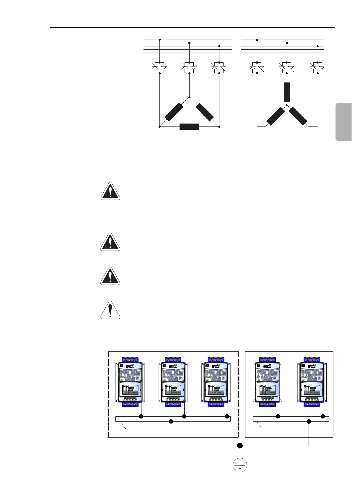
ATTENTION!
Do not share the ground wiring with other equipment that operate with
high current (for examples: high voltage motors, welding machines,
etc.). When several Soft-Starters SSW-07 are used, observe the
connections in the gure 3.8.
GROUNDING BAR
BARRA DE ATERRAMENTO
INTERNAL TO THE PANEL
INTERNA AO PAINEL
GROUNDING BAR
BARRA DE ATERRAMENTO
INTERNAL TO THE PANEL
INTERNA AO PAINEL
Figure 3.8 - Grounding connections for more than one Soft-Starter SSW-07
23
CHAPTER 3 - INSTALLATION AND CONNECTION
EMI - Electronic Interference
The Soft-Starter SSW-07 is developed to be used in industrial
systems (Class A) according to Standard EN60947-4-2.
It’s necessary to have a distance of 0.25 m (10 in) between the
Soft- Starter SSW-07 control cables and motor cables.
Example: PLC wiring, temperature controllers, thermocouple cables, etc.
Grounding of the Motor frame
Always ground the motor frame. The Soft-Starter SSW-07 output
wiring to the motor must be installed separately from the input wiring
as well as from the control and signal wiring.
English
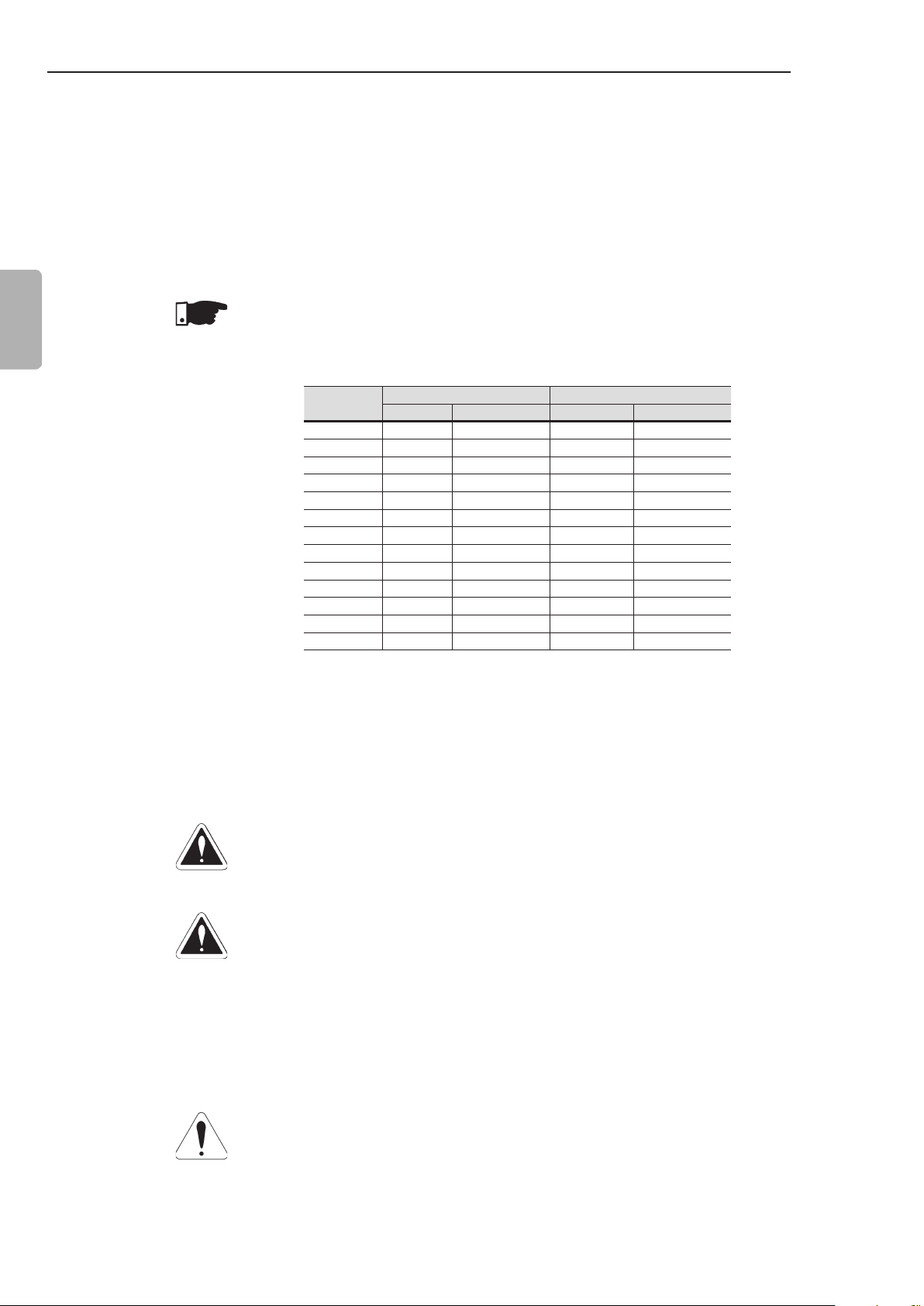
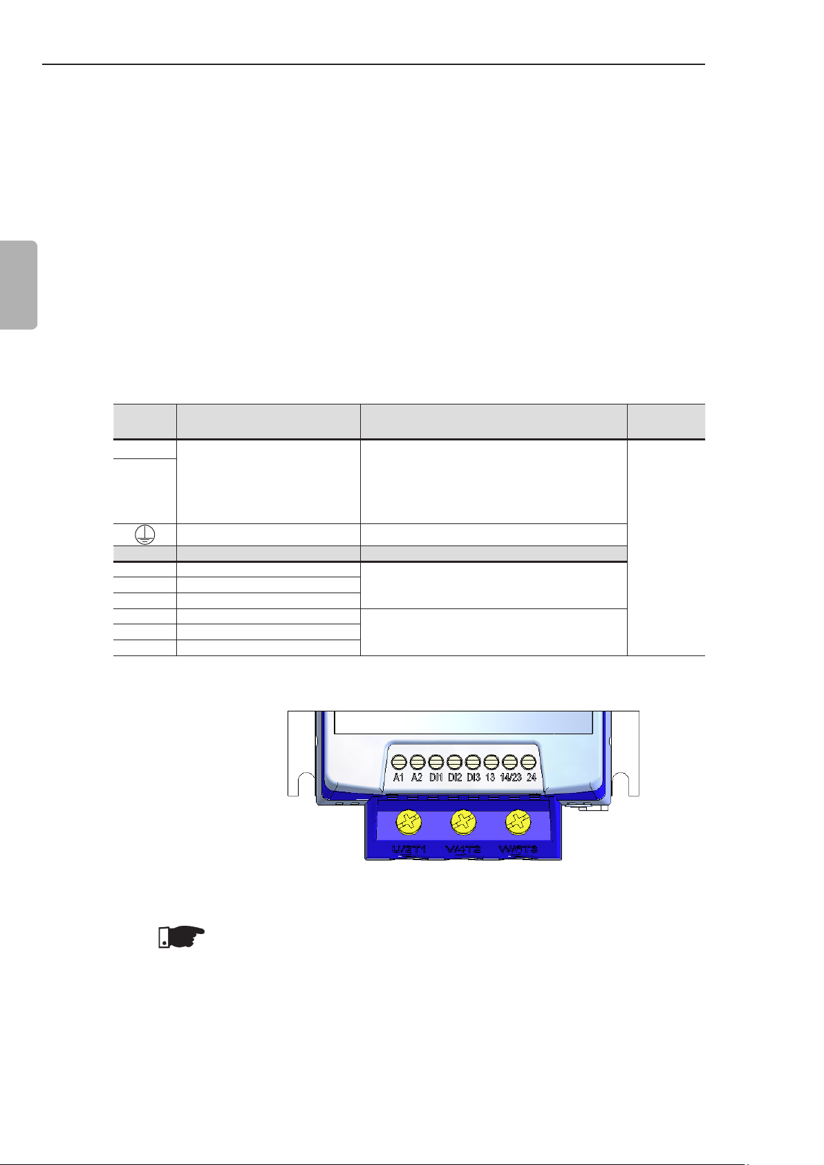
3.2.7 Control and Signal Connections
Terminal Description Specications
A1
A2
Terminal Factory Default Specications
DI1 Starts/Stops Motor
DI2 Fault reset
DI3 Fault reset
13 Relay 1 output - Operation
14/23 Relay common point
24 Relay 2 output - Full voltage
The control connections (digital inputs and relay outputs) are made
through the terminals (refer to gure 3.9).
Voltage: 110 to 240 Vac (-15 % to +10 %)
(models from 17 A to 200 A)
Electronics Supply
Grounding Only for the 255 to 412 A models
Table 3.9 - Description of the control connector pins
110 to 130 Vac or 208 to 240 Vac
(-15 % to 10 %) (models from 255 A
to 412 A).
3 isolated digital inputs
Voltage: 110 to 240 Vac (-15 % to +10 %)
Current: 2 mA Max.
Contact capacity:
Voltage: 250 Vac
Current: 1 A
Torque Nm
(in lb)
0.5 (4.5)
24
Figure 3.9 - Control terminals of the Soft-Starter SSW-07
NOTE!
It is recommended to use shielded cables for the Dix inputs when
using long cables (above 30 m) in noisy environments. The metallic
shield and A2 must be grounded.
CHAPTER 3 - INSTALLATION AND CONNECTION
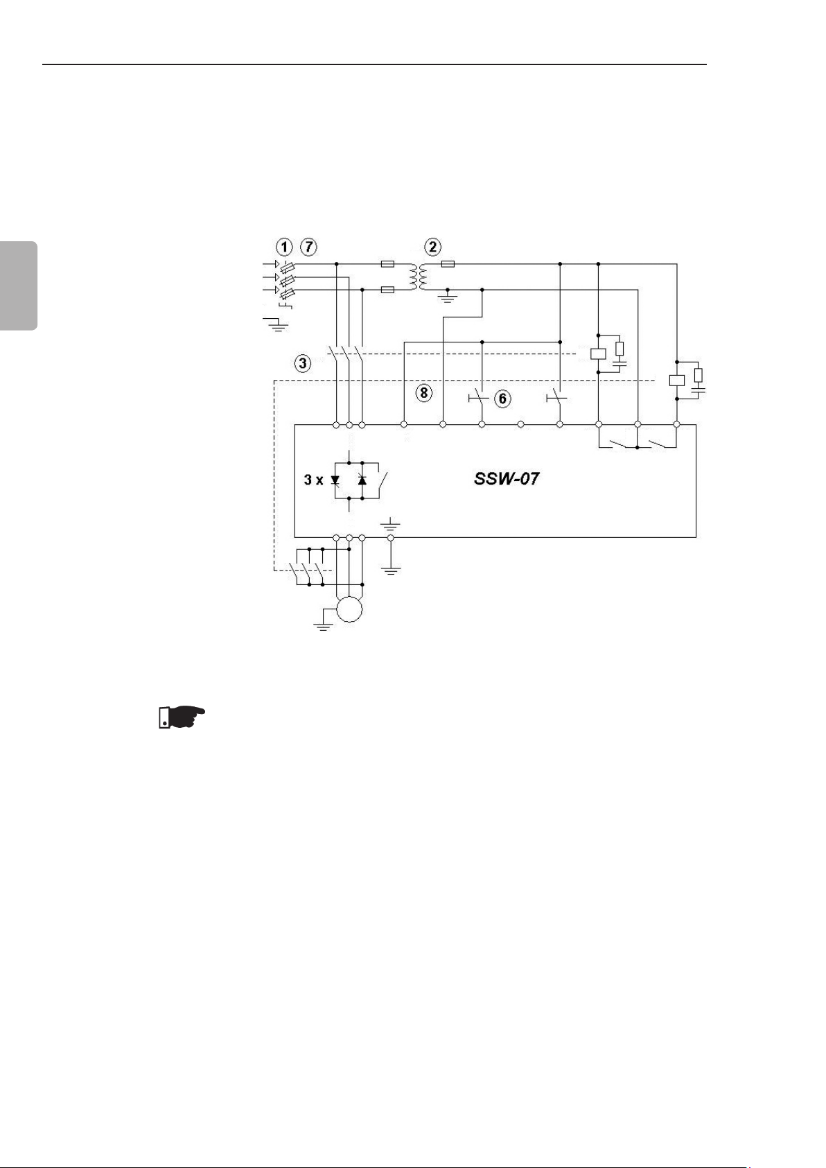
3.3 RECOMMENDED SET-UPS
Some recommended set-ups are shown here and they can be
completely or partly used.
The main warning notes for all the recommended set-ups are
shown below and are described in the schemes by their respective
numbers.
NOTES!
The use of fuses or circuit breakers at the input circuit is
1
necessary for the entire installation protection. It is not necessary
to use ultra-fast fuses for the SSW-07 operation; however, their
use is recommended for the soft-starter complete protection.
The transformer “T1” is optional and must be used when there
2
is a dierence between the line voltage and the electronic power
voltage.
In case that damage at the SSW-07 Soft-Starter power circuit
3
keeps the motor running (e.g., shorted thyristors), the motor
protection is obtained with the use of the power isolating
contactor (K1) or circuit breaker (Q1).
English
Start push-button.
4
Stop push-button.
5
Start/Stop switch. Bear in mind that when using two-wire digital
6
input command (normally open switch with retention), in case
of a power interruption, upon return of power, the motor will be
started immediately if the switch remains closed.
In case of maintenance of the Soft-Starter SSW-07 or the motor
7
it is necessary to remove the input fuses or disconnect the power
supply to ensure the complete equipment disconnection from
the power supply.
The emergency stop can be used by disconnecting the
8
electronics power supply.
Undervoltage release for the Q1 power isolation circuit breaker.
9
25
CHAPTER 3 - INSTALLATION AND CONNECTION
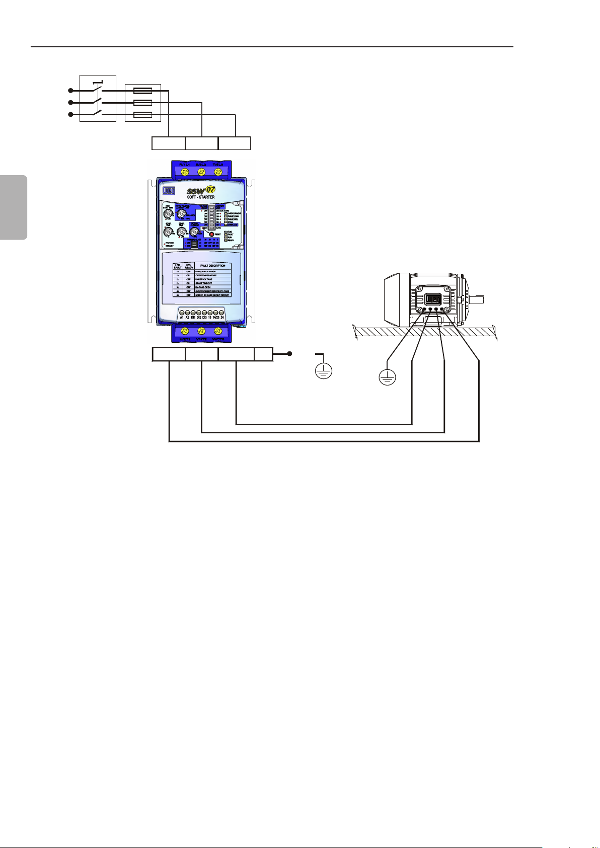
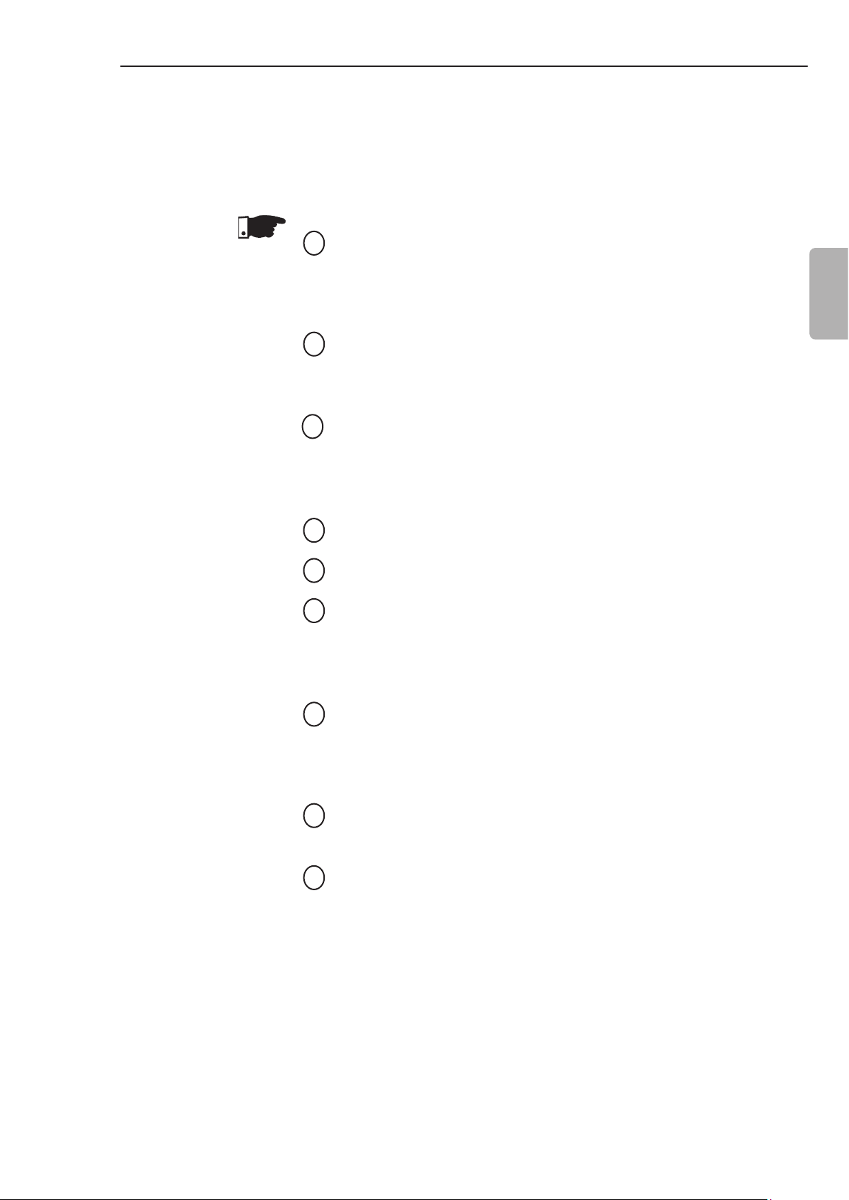
3.3.1 Recommended Set-up with Command via Two-wire Digital Inputs and Isolation Contactor
English
Refer to notes in item 3.3.
R
S
T
PE
K1
R S T
U V W
M
3~
T1
K1
RL1
23
14
24
RL2
DI1A2A1
DI2
DI3
13
Figure 3.10 - Recommended set-up with commands via two-wire digital inputs
and isolation contactor
3.3.2 Recommended
Set-up with
Command
via Threewire Digital
Inputs and
Circuit- Breaker
Refer to notes in item 3.3.
R
S
T
PE
Q1
R S T
U V W
M
3~
T1
Q1
DI1A2A1
DI2
DI3
13
14
23
RL1 RL2
24
26
Figure 3.11 - Recommended set-up with commands via three-wire digital
inputs and a circuit-breaker
NOTE!
It’s necessary to program the digital input DI2 for the three-wire
command function. Refer to item 4.10.
NOTE!
The RL1 shall be set to the “No fault” function. Refer to item 4.12.
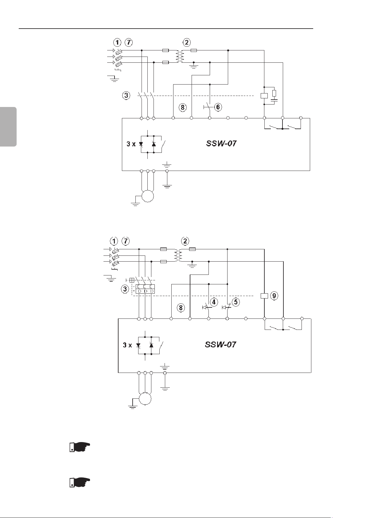
3.3.3 Recommended Set-up with Command via Two-wire Digital Inputs and Direction of Rotation
P220 = 1
P230 = 1
P263 = 1 (DI1 = Start/Stop two
wires)
P265 = 4 (DI3 = Rotation
Direction)
P277 = 4 (RL1 = FWD/REV - K1)
P278 = 4 (RL2 = FWD/REV - K2)
P620 = 0 (RST phase sequence
= Inactive)
CHAPTER 3 - INSTALLATION AND CONNECTION
R
S
T
PE
K1
K2 K2
T1
K1
English
Refer to notes in item 3.3.
Figure 3.12 - Recommended Set-up with Command via Two-wire Digital
NOTE!
To program the parameters shown above, is necessary the use of
keypad or serial communication. See the Programming Manual for
more information.
R S T
U V W
M
3~
DI1A2A1
Inputs and Direction of Rotation
DI2
DI3
RL1
23
14
24
RL2
13
27
CHAPTER 3 - INSTALLATION AND CONNECTION
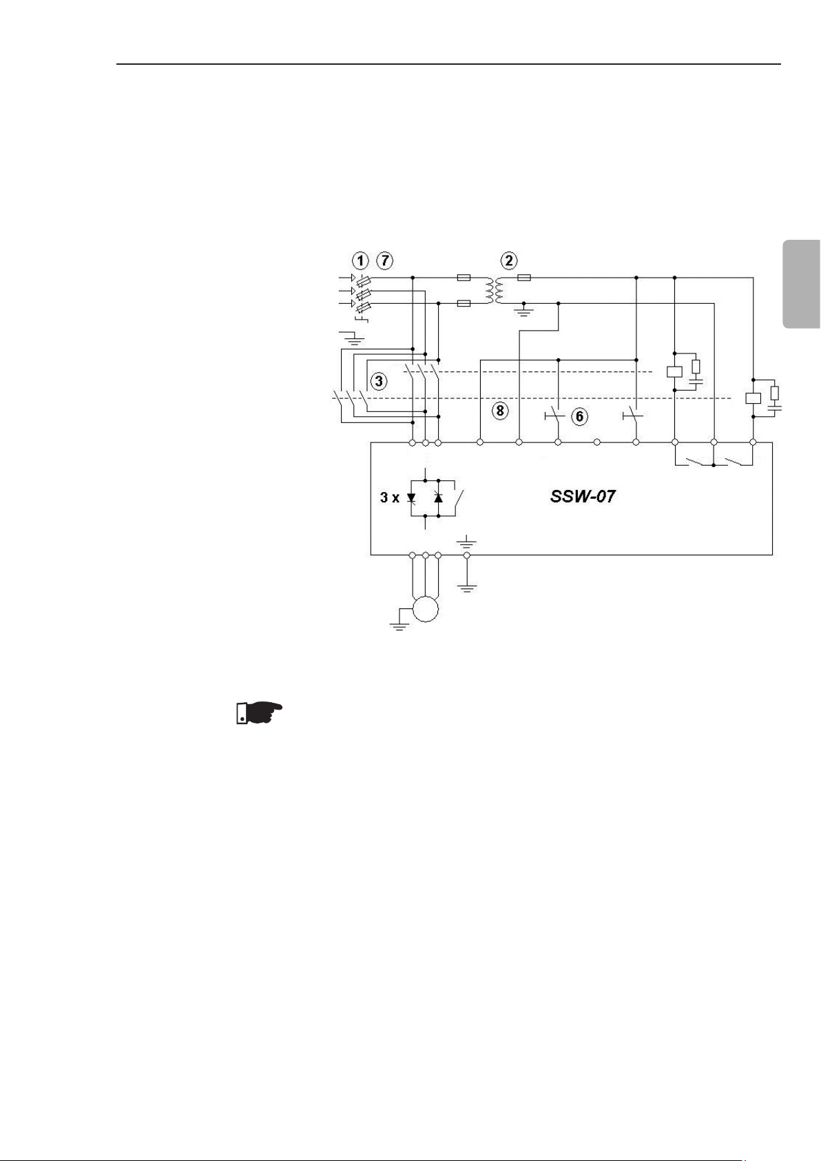
3.3.4 Recommended
Set-up with
Command via
Two-wires Digital
Inputs and DCBraking
P220 = 1
P230 = 1
P263 = 1 (DI1 = Start/Stop two
wires)
English
P265 = 5 (DI3 = Brake O)
P277 = 1 (RL1 = Running)
P278 = 5 (RL2 = DC-Braking)
P501 ≥ 1 (DC Braking Time ≥ 1s)
R
S
T
PE
K1
T1
K1
K2
Refer to notes in item 3.3.
NOTE!
To program the parameters shown above, is necessary the use of
keypad or serial communication. See the Programming Manual for
more information.
K2
R S T
U V W
M
3~
DI1A2A1
DI2
DI3
13
RL1
23
14
24
RL2
Figure 3.13 - Recommended Set-up with Command via Two-wires Digital
Inputs and DC-Braking
28
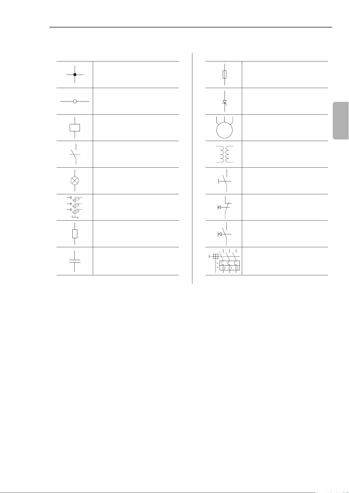
3.3.5 Symbols
CHAPTER 3 - INSTALLATION AND CONNECTION
Electrical connection between
two signals
Connection terminals Thyristor/SCR
Relay or contactor coil
M
3~
Normally open contact (NO) Transformer
Indicator light N.O Contact (with retention)
Circuit-breaker
(opens under load)
Resistor Normally open (NO)
Fuse
Three-phase motor
Normally closed (NC)
push-button
push-button
English
Capacitor Circuit-breaker with
undervoltage release
29
 Loading...