

Page 1
Phone: 800.894.0412 - Fax: 888.723.4773 - Web: www.clrwtr.com - Email: info@clrwtr.com
Page 2

Phone: 800.894.0412 - Fax: 888.723.4773 - Web: www.clrwtr.com - Email: info@clrwtr.com
Page 3

Serie: SSW-06
Software:version1.3X
0899.5579 E/6
SOFT-STARTER
MANUALSSW-06
ATTENTION!
It is very important to check if the
Soft-Starter Software is the same as
mentioned above.
12/2006
Phone: 800.894.0412 - Fax: 888.723.4773 - Web: www.clrwtr.com - Email: info@clrwtr.com
Page 4

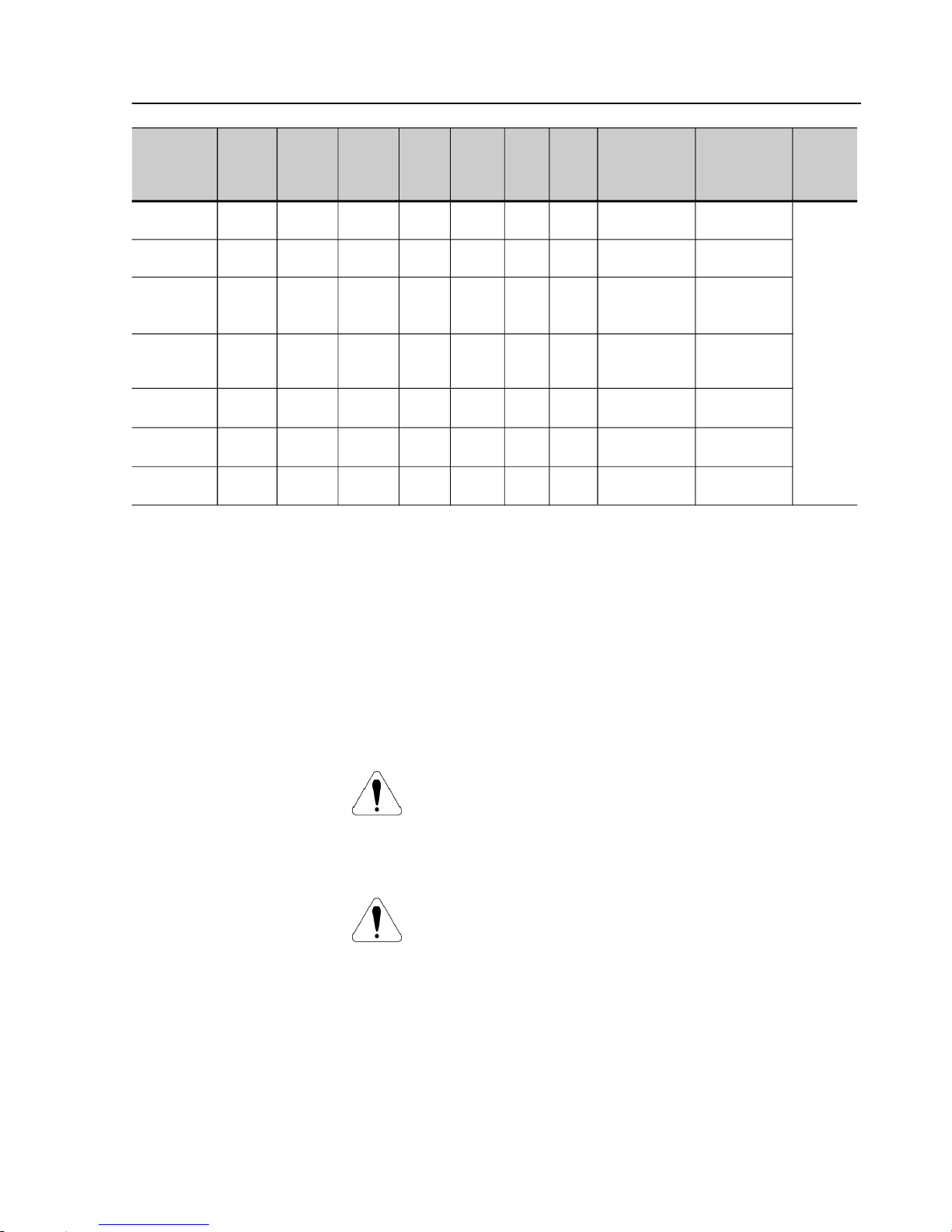
Summaryof Revisions
The tablebelowdescribes therevisions made to this manual.
Revision Description Section
1 FirstEdition 2 General Revision 3 General Revision 4 New Software Version 5 Implementation of the following current: 412A, Chap 3
480A, 604A, 670A, 820A, 950A, 1100A and 1400A. and 10
New software version with: braking methods 3, 4, 6
FWD/REVandJog. and 8
P140 was changed. E73 was eliminated.
E71 and E76 were changed.
6 General Revision -
Phone: 800.894.0412 - Fax: 888.723.4773 - Web: www.clrwtr.com - Email: info@clrwtr.com
Page 5

Summary
Quick Parameter Reference,
Fault and Status Messages
I Parameters..................................................................................... 09
II FaultMessages.............................................................................. 17
III OtherMessages............................................................................. 17
CHAPTER 1
Safety Notices
1.1 Safety Notices inthe Manual.......................................................... 18
1.2 Safety Notice on the Product.......................................................... 18
1.3 PreliminaryRecommendations ....................................................... 19
CHAPTER 2
General Information
2.1 About this Manual .......................................................................... 20
2.2 SoftwareVersion............................................................................. 20
2.3 Aboutthe Soft-Starter SSW-06....................................................... 20
2.4 Soft-StarterSSW-06Identification .................................................. 23
2.5 ReceivingandStorage .................................................................... 25
CHAPTER 3
Installation and Connection
3.1Mechanical Installation ..................................................................... 26
3.1.1EnvironmentConditions .............................................................. 26
3.1.2Dimensions of the Soft-StarterSSW-06...................................... 26
3.1.3MountingSpecifications.............................................................. 27
3.1.3.1 Mounting inside a Panel .................................................... 28
3.1.3.2Mounting on a surface ....................................................... 30
3.2 Electrical Installation......................................................................... 31
3.2.1PowerTerminals ......................................................................... 32
3.2.2Locationof thePower/ Grounding, Control Connectionsand
Fan VoltageSelection ................................................................ 36
3.2.3RecommendedPower/GroundingCables ................................... 38
3.2.4AC InputConnection ................................................................... 39
3.2.4.1 Power Supply Capacity ..................................................... 40
3.2.4.2RecommendedFuses ....................................................... 40
3.2.5OutputConnection...................................................................... 41
3.2.5.1StandardThree-WireConnection(P150=0=Inactive).......... 41
3.2.5.2InsideDelta Motor Connection(P150=1=Active) ............... 42
3.2.6Grounding Connections .............................................................. 43
3.2.7Fan Connection and Selection of Fan Voltage ............................ 44
3.2.8Signaland Contro Connections .................................................. 45
3.2.9RS-232,X2SerialCommunicationConnection........................... 48
Phone: 800.894.0412 - Fax: 888.723.4773 - Web: www.clrwtr.com - Email: info@clrwtr.com
Page 6

Summary
3.2.10RS-485,XC8 IsolatedSerialCommunication
Board Connection .................................................................... 48
3.2.11 XC6FieldbusCommunicationBoard Connection ...................... 48
3.3RecommendedSet-Ups.................................................................... 48
3.3.1Recommended Set-ups by Keypad(HMI) Command
with Isolating Contactor. Notes in 3 .3. ....................................... 50
3.3.2Recommended Set-ups by Keypad(HMI) Command
withCircuit-breaker.Notes in 3.3................................................ 50
3.3.3Recommended Set-ups withCommandviaTwo-wire
Digital Inputs. Notesin 3.3. ........................................................ 51
3.3.4RecommendedSet-upswithCommand viaThree-wire
Digital Inputs. Notesin 3.3. ........................................................ 51
3.3.5RecommendedSet-upswithCommand viaThree-wire
DigitalInput and Inside Delta Motor Connection. Notes in 3.3
and3.2.5.2. ................................................................................ 52
3.3.6RecommendedSet-upswithCommand viaThree-wire
DigitalInput or Serial Communication. Notes in 3.3. .................. 52
3.3.7RecommendedSet-upswithCommand viaThree-wire
DigitalInput or Fieldbus Communication. Notes in 3.3. .............. 53
3.3.8 RecommendedSetup withCommandvia DigitalInputs and
directionofrotation ..................................................................... 53
3.3.9 RecommendedSetup withCommandvia DigitalInputs and
ReverseBraking ......................................................................... 54
3.3.10Recommended Setup with Commandvia Digital Inputsand
Optimal Braking ....................................................................... 54
3.3.11Recommended SetupwithCommand viaDigitalInputsand
DC-Braking............................................................................... 55
3.3.12Recommended Setup with Commandvia Digital Inputsand
External By-pass Contactor ..................................................... 55
3.3.13 Symbols ................................................................................... 56
3.4 EuropeanDirectivesforElectromagneticCompatibility
Requirementsfor installation .......................................................... 57
3.4.1Installation .................................................................................. 57
CHAPTER 4
Keypad (HMI) Operation
4.1 Descriptionof the Keypad (HMI-SSW-06) ..................................... 59
4.2 Useof the Keypad (HMI) ................................................................ 61
4.2.1KeypadUse for Soft-StarterSSW-06 Operation ......................... 61
4.2.2HMI Display-Signalingindications............................................... 62
4.2.3ParameterViewingand Programming......................................... 63
CHAPTER 5
Start-up
5.1 Power-upPreparation ..................................................................... 65
5.2 InitialPower-up............................................................................... 66
5.3 Start-up........................................................................................... 73
5.3.1 Start-upOperationviaKeypad(HMI)-
Phone: 800.894.0412 - Fax: 888.723.4773 - Web: www.clrwtr.com - Email: info@clrwtr.com
Page 7

Summary
Typeof Control:VoltageRamp .................................................. 74
CHAPTER6
Detailed Parameter Description
6.1 Access and Read-OnlyParameters - P000 to P099 ...................... 77
6.2 RegulationParameters - P100 toP199 ..........................................82
6.3 ConfigurationParameters-P200 to P299....................................... 91
6.4 Communication Parameters - P300to P399 .................................. 104
6.5 Motor Parameters - P400 to P499.................................................. 106
6.6 SpecialFunction Parameters - P500 to P599................................. 107
6.7 Protection Parameters - P600 to P699........................................... 113
CHAPTER7
Applications and Programming
7.1Applicationsand Programming ......................................................... 121
7.1.1Startingby VoltageRamp (P202=0)............................................ 123
7.1.2 Startingby Current Limit (P202=1)..............................................124
7.1.3StartingbyCurrentRamp (P202=4) ............................................ 125
7.1.4StartingbyCurrentRamp (P202=4) ............................................ 126
7.1.5StartingwithPump Control (P202=2) .......................................... 127
7.1.6Starting with TorqueControl(P202=3)......................................... 129
7.1.6.1Loads with constant torque (P202=3 and P120=1 point) .... 130
7.1.6.2 Loads with high initial torque (P202=3 and P120=3 points) 130
7.1.6.3Loads with constant torque and Sspeed curve
(P202=3 and P120=3 points) ............................................. 131
7.1.6.4Loads withquadratic torqueand Sspeed curve
(P202=3 and P120=2 points) ............................................. 131
7.1.6.5Loadswith quadratic torqueand linear speedcurve
(P202=3 and P120=3 points) ............................................. 132
7.1.6.6Loads withquadratic torqueand higherinitial torque
(P202=3 and P120=3 points) ............................................. 132
7.1.6.7Hydraulic pump load type (P202=3).................................... 133
7.2Protectionsand Programming .......................................................... 136
7.2.1ThermalClasses......................................................................... 136
7.2.1.1 Suggestions about thermal class setting............................ 136
7.2.1.2Example of how toprogram the Thermal Class .................. 137
7.2.1.3Time reductionwhenchanging from cold starting
to hot starting ..................................................................... 138
7.2.1.4ServiceFactor .................................................................... 138
CHAPTER8
Diagnosis and Troubleshooting
8.1 Faults and Possible Causes ............................................................. 139
8.2Troubleshooting ................................................................................ 143
Phone: 800.894.0412 - Fax: 888.723.4773 - Web: www.clrwtr.com - Email: info@clrwtr.com
Page 8

Summary
8.3ContactingWEG Telephone/Fax/E-mailfor Contact (Servicing)........ 143
8.4PreventiveMaintenance .................................................................... 144
8.4.1CleaningInstructions .................................................................. 145
8.5 Spare Parts List ................................................................................ 145
CHAPTER 9
Options and Accessories
9.1Remote Keypad (HMI)and Cables.................................................... 146
9.2RS-485for theSoft-StarterSSW-06 ................................................. 148
9.2.1RS-485 Communication Kit for theSSW-06 ............................... 148
9.2.2OptionalMIW-02 Module ............................................................ 149
9.3 Fieldbus Communication Kits ........................................................... 149
9.3.1Fieldbus DeviceNet CommunicationKit for the SSW-06............. 149
9.3.2Fieldbus Profibus DP Communicationkit for the SSW-06 .......... 150
CHAPTER10
Technical Specifications
10.1 CurrentsandRatingsAccordingto Ul508 ....................................... 151
10.2 Currentsand Ratings for IP55,IV PoleWeg Motor ......................... 152
10.3 PowerData..................................................................................... 153
10.4 Electronics/Programming Data....................................................... 153
10.5 MechanicalData............................................................................. 155
Phone: 800.894.0412 - Fax: 888.723.4773 - Web: www.clrwtr.com - Email: info@clrwtr.com
Page 9
9
SSW-06- QUICK PARAMETER REFERENCE
QUICK PARAMETER REFERENCE, FAULT AND STATUS MESSAGES
Software:V1.3X
Application:
Model:
SerialNumber:
PersonResponsible:
Date: / / .
I.Parameters
Parameter Description Adjustable Range
Factory
Unit
User´s
Page
Setting Setting
P000 Access Parameter 0 to 999 0 - 77
READONLY PARAMETERS P001 to P099
P001 Soft-Starter Current 0 to 999.9 - % 78
(%In of the Soft-Starter)
P002 Motor Current (%In of the Motor) 0 to 999.9 - % 78
P003 Motor Current 0 to 9999.9 - A 78
P004 Power Supply Voltage 0 to 999 - V 78
P005 Network Frequency 0 to 99.9 - Hz 78
P006 Soft-Starter Status 0=rdy - ready - - 78
1=Sub - Sub
2=Exx - Error
3=ruP - Run Up
4=FuLL- Full Volt.
5=PASS - By-pass
6=ECO - Reserved
7=rdo - Run Down
8=br - Braking
9=rE- FWD/REV
10=JOG-JOG
11=dly- Delay P630
12=G.di - Gen. Disable
P007 Output Voltage 0 to 999 - V 79
P008 Power Factor 0 to 1.00 - - 79
P009 Motor Torque (% Tn of the Motor) 0 to 999.9 - % 79
P010 Output Power 0 to 6553.5 - kW 79
P011 Apparent Output Power 0 to 6553.5 - kVA 79
P012 Digital InputStatusDl1 to Dl6 0 = Inactive - - 80
1 = Active
P013 Status RL1, RL2 and RL3 0 = Inactive - - 80
1 = Active
P014 Last Fault 03 to 77 - - 81
P015 Second Previous Fault 03 to 77 - - 81
P016 Third Previous Fault 03 to 77 - - 81
P017 Fourth Previous Fault 03 to 77 - - 81
P023 Software Version X.XX - - 81
P030 Current of Phase R 0 to 9999.9 - A 81
P031 Current of Phase S 0 to 9999.9 - A 81
P032 Current of Phase T 0 to 9999.9 - A 81
P033 R-S Line Voltage 0 to 999 - V 81
P034 S-T Line Voltage 0 to 999 - V 81
P035 T-RLine Voltage 0 to 999 - V 81
Phone: 800.894.0412 - Fax: 888.723.4773 - Web: www.clrwtr.com - Email: info@clrwtr.com
Page 10

SSW-06- QUICK PARAMETER REFERENCE
10
Parameter Description Adjustable Range
Factory
Unit
User´s
Page
Setting Setting
P042 Time Powered 0 to 65530 - h 81
P043 TimeEnabled 0 to 6553 - h 82
P050 MotorThermal Protection Status 0 to 250 - % 82
P085 FieldbusCommunication Board Status 0=Off - - 82
1=Board Inactive
2=Board Active and Offline
3=Board Active and Online
REGULATION PARAMETERS P100TO P199
Voltage Ramp
P101 Initial Voltage(% Un of the motor) 25 to 90 30 % 82
P102 Acceleration Ramp Time 1 to 999 20 s 83
P103 Deceleration Voltage Step 100=Inactive 100=Inactive % 84
(% Un of the motor) 99 to 60
P104 DecelerationRampTime 0=Inactive 0=Inactive s 84
1 to 299
P105 End Deceleration Voltage 30 to 55 30 % 84
(% Un of the Motor)
Current Limit
P110 CurrentLimit 150 to 500 300 % 84
(%In of the Motor current)
P111 Initial Current for the Current Ramp 150 to 500 150 % 85
(% In of the Motor)
P112 Time for the Current Ramp 1 to 99 20 % 85
(% of P102)
Torque Control
P120
(1)
Starting Torque Characteristics 1=Constant 1=Constant - 86
2=Linear
3=Quadratic
P121 Initial StartingTorque (% Tn of Motor) 10 to 400 30 % 87
P122 End Starting Torque(% Tn of Motor) 10 to 400 110 % 87
P123 MinimumStartingTorque 10 to 400 27 % 87
(% Tn of the Motor)
P124 Time for the Minimum Start Torque 1 to 99 20 % 87
(% of P102)
P125
(1)
Stopping Torque Characteristics 1=Constant 1=Constant - 88
2=Linear
3=Quadratic
P126 End Stop Torque(% Tn of the Motor) 10 to 100 20 % 88
P127 MinimumStopTorque 10 to 100 50 % 89
(% Tn of the Motor)
P128 Time for the Minimum StopTorque 1 to 99 50 % 89
(% of P104)
Pump Control
P130
(1)
PumpControl 0=PumpI 0=PumpI - 89
1=PumpII
By-pass
P140
(1)
External By-pass Contactor 0=Inactive 0=Inactive - 89
1=Active
Phone: 800.894.0412 - Fax: 888.723.4773 - Web: www.clrwtr.com - Email: info@clrwtr.com
Page 11

11
SSW-06- QUICK PARAMETER REFERENCE
Parameter Description Adjustable Range
Factory
Unit
User´s
Page
Setting Setting
Inside Delta
P150
(1) (2)
Inside Delta Motor Connection 0=Inactive 0=Inactive - 90
1=Active
CONFIGURATION PARAMETERS P200 to P399
P200 Password 0=Inactive 1=Active - 91
1=Active
P201
(2)
Language Selection 0=Portuguese To be defined - 91
1=English by the user
2=Spanish
3=German
P202
(1)
Type of the Control 0=Voltage Ramp 0=Voltage Ramp - 91
1=Current limiting
2=PumpControl
3=Torque Control
4=CurrentRamp
P204
(1)
Load/Save Parameters 0=Not use 0=Not use - 94
1=Not use
2=Not use
3=ResetP043
4=Not use
5=Loads Factory Default
6=Not use
7=Loads User Default 1
8=Loads User Default 2
9=Not use
10=Saves User Default 1
11=Saves User Default 2
P205 Display Default Selection 0=P001 2=P003 - 95
1=P002
2=P003
3=P004
4=P005
5=P006
6=P007
7=P008
P206 Auto-Reset Time 0=Inactive 0=Inactive s 95
1 to 600
P215
(1)
Keypad Copy Function 0=Inactive 0=Inactive - 96
1=SSWHMI
2=HMISSW
P218 LCD Display Contrast Adjust. 0 to 150 127 - 97
Local/Remote Definition
P220
(1)
Local/Remote Source Selection 0=Always Local 2=HMI(L) - 97
1=Always Remote
2=HMI(L)
3=HMI(R)
4=DI4toDI6
5=Serial(L)
6=Serial(R)
7=Fieldbus(L)
8=Fieldbus(R)
Phone: 800.894.0412 - Fax: 888.723.4773 - Web: www.clrwtr.com - Email: info@clrwtr.com
Page 12

SSW-06- QUICK PARAMETER REFERENCE
12
Parameter Description Adjustable Range
Factory
Unit
User´s
Page
Setting Setting
P229
(1)
LocalStatusCommand Selection 0=KeysHMI 0=KeysHMI - 97
1=DigitalInputs DIx
2=Serial
3=Fieldbus
P230
(1)
RemoteStatusCommandSelection 0=KeysHMI 1=DIxTerminals - 97
1=DigitalInputs DIx
2=Serial
3=Fieldbus
P231
(1)
FWD/REVSelection 0=Not used 0=Not used - 98
1=By Contactor
2=JOGOnly
Analog Outputs
P251 AO1 (0 to 10)V Output Function 0=Not used 0=Not used - 99
1= Current (%In of the SSW)
2=Input Voltage
(%Un of the SSW)
3=Output voltage
(%Un of the SSW)
4=Power Factor
5=ThermalProtection
6=Power (in W)
7=Power (in VA)
8=Torque (%Tn of Motor)
9=Fieldbus
10=Serial
P252 AO1 Analog Output Gain 0.000 to 9.999 1.000 - 99
P253 AO2 (0 to 20)mA or (4 to 20)mA 0=Not used 0=Not used - 99
Output Function 1= Current (%In of the SSW)
2=Input Voltage
(%Un of the SSW)
3=Output voltage
(%Un of the SSW)
4=Power Factor
5=ThermalProtection
6=Power (in W)
7=Power (in VA)
8=Torque (%Tn of the Motor)
9=Fieldbus
10=Serial
P254 AO2 Analog Output Gain 0.000 to 9.999 1.000 - 99
P255 AO2 Analog Output Selection 0=0 to 20 0=0 to 20 mA 99
1=4 to 20
Digital Inputs
P264
(1)
DI2Digital InputFunction 0=Not Used 2= Reset - 100
1=Stop (Three-Wire)
2=Reset
P265
(1)
DI3Digital InputFunction 0=Not Used 0=Not used - 100
1=GeneralEnable
2=Reset
Phone: 800.894.0412 - Fax: 888.723.4773 - Web: www.clrwtr.com - Email: info@clrwtr.com
Page 13

13
SSW-06- QUICK PARAMETER REFERENCE
Parameter Description Adjustable Range
Factory
Unit
User´s
Page
Setting Setting
P266
(1)
DI4Digital InputFunction 0=Not Used 0=Not Used - 100
1=FWD/REV
2=Local/Remote
3=NoExternalFault
4=JOG
5=Brake Off
6=Reset
P267
(1)
DI5Digital InputFunction 0=Not Used 0=Not used - 101
1=FWD/REV
2=Local/Remote
3=NoExternalFault
4=JOG
5=Brake Off
6=Reset
P268
(1)
DI6Digital InputFunction 0=Not used 0=Not used - 101
1=FWD/REV
2=Local/Remote
3=No external Fault
4=JOG
5=Brake Off
6=Reset
7=MotorThermistor
Digital Outputs
P277
(1)
RL1 Relay Function 0=Not used 1=Running - 102
1=Running
2=Fullvoltage
3=External By-pass
4=FWD/REV-K1
5=DC-Brake
6=NoFault
7=Fault
8=Fieldbus
9=Serial
P278
(1)
RL2 Relay Function 0=Not used 2=FullVoltage - 102
1=Running
2=Fullvoltage
3=External By-pass
4=FWD/REV-K2
5=DC-Brake
6=NoFault
7=Fault
8=Fieldbus
9=Serial
P279
(1)
RL3 Relay Function 0=Inactive 6=NoFault - 102
1=Running
2=Fullvoltage
3=External By-pass
4= Not used
5=DC-Brake
6=NoFault
Phone: 800.894.0412 - Fax: 888.723.4773 - Web: www.clrwtr.com - Email: info@clrwtr.com
Page 14

SSW-06- QUICK PARAMETER REFERENCE
14
Parameter Description Adjustable Range
Factory
Unit
User´s
Page
Setting Setting
7=Fault
8=Fieldbus
9=Serial
Soft-Starter Data
P295
(1)(2)
SSW Rated Current 0=10A 11=312A According to A 103
1=16A 12=365A Soft-Starter
2=23A 13=412A Rated Current
3=30A 14=480A
4=45A 15=604A
5=60A 16=670A
6=85A 17=820A
7=130A 18=954A
8=170A 19=1100A
9=205A 20=1411A
10=255A
P296
(1) (2)
Rated Voltage 0=220/575V According to V 103
1=575/690V Soft-Starter
Voltage
PARÂMETROS DE COMUNICAÇÃO SERIAL P300 a P399
P308
(1)(2)
Soft-Starter Address on the Serial 1 to 247 1 - 104
Communication Network
P309
(1)(2)
FieldbusCommunication 0=Inactive 0=Inactive - 104
BoardEnabling 1=Profibus-DP
(1 Inputs and 1 Outputs)
2=Profibus-DP
(4 Inputs and 4 Outputs)
3=Profibus-DP
(7 Inputs and 7 Outputs)
4=DeviceNet
(1 Inputs and 1 Outputs)
5=DeviceNet
(4 Inputs and 4 Outputs)
6=DeviceNet
(7 Inputs and 7 Outputs)
P312
(1)(2)
Protocol Type and Serial 1=Modbus-RTU 1=Modbus-RTU 104
Communication Transfer Rate (9600bps, no parity) (9600bps,
2=Modbus-RTU no parity)
(9600bps, odd)
3=Modbus-RTU
(9600bps, even)
4=Modbus-RTU
(19200bps, no parity)
5=Modbus-RTU
(19200bps, odd)
6=Modbus-RTU
(19200bps, even)
7=Modbus-RTU
(38400bps, no parity)
8=Modbus-RTU
(38400bps, odd)
Phone: 800.894.0412 - Fax: 888.723.4773 - Web: www.clrwtr.com - Email: info@clrwtr.com
Page 15
15
SSW-06- QUICK PARAMETER REFERENCE
Parameter Description Adjustable Range
Factory
Unit
User´s
Page
Setting Setting
9=Modbus-RTU
(38400bps, even)
P313 Serialand FieldbusCommunication 0=Inactive 0=Inactive 104
ErrorActions (E28, E29 and E30) 1=Disable
2=GeneralEnable
3=Changes to Local
P314
(1)
TimeoutTime for Serial 0 to 999 0= Inactive s 105
CommunicationTelegramReception
P315
(1)
Read Parameter via Fieldbus 1 0 to 999 0 - 105
P316
(1)
Read Parameter via Fieldbus 2 0 to 999 0 - 105
P317
(1)
Read Parameter via Fieldbus 3 0 to 999 0 - 105
MOTOR PARAMETERS P400 to P499
P400
(1)
Rated Motor Voltage 0 to 999 380 V 106
P401
(1)
Rated Motor Current 0.0 to 1500 20 A 106
P403
(1)
Rated Motor Speed 400 to 3600 1780 rpm 106
P404
(1)
Rated Motor Power 0.1 to 2650 75 kW 106
P405
(1)
Motor Power Factor 0 to 1.00 0.89 - 106
P406
(1)
Service Factor 0 to 1.50 1.00 - 106
SPECIAL PARAMETERS P500 to P599
Braking
P500
(1)
Braking Methods 0=Inactive 0=Inactive - 107
1=Reverse Braking
2=OptimalBraking
3=DC-Braking
P501 BrakingTime 1 to 299 10 s 110
P502 Braking Voltage Level 30 to 70 30 % 110
P503 Braking End Detection 0=Inactive 0=Inactive - 110
1=Automatic
JOG
P510
(1)
Jog 0=Inactive 0=Inactive - 111
1=Active
P511 Jog Level 10 to 100 30 % 111
Kick Start
P520
(1)
Kick Start TorquePulse 0=Inactive 0=Inactive - 112
(according to P202) 1=Active
P521 Kick StartPulseTime 0.1 to 2 0.1 s 112
P522 Kick Start Voltage Pulse Level 70 to 90 70 % 112
(% Un of the Motor)
P523 Kick Start Current Pulse Level 300 to 700 500 % 112
(% In of the Motor)
PROTECTION PARAMETERS P600 to P699
Voltage Protection
P600
(1)
Undervoltage (% Un of the motor) 0 to 30 20 % 113
P601
(1)
ImmediateUndervoltageTime 0=Inactive 1 s 113
1 to 99
P602
(1)
Overvoltage (% Un of the motor) 0 to 20 15 % 113
P603
(1)
ImmediateOvervoltageTime 0=Inactive 1 s 113
1 to 99
P604
(1)
Voltage Imbalance Between Phases 0 to 30 15 % 114
(% Un of the motor)
Phone: 800.894.0412 - Fax: 888.723.4773 - Web: www.clrwtr.com - Email: info@clrwtr.com
Page 16

SSW-06- QUICK PARAMETER REFERENCE
16
Parameter Description Adjustable Range
Factory
Unit
User´s
Page
Setting Setting
Notes presented on quick parameter description:
(1) This parameter can only be changed with the motor stopped.
(2) This parameter does not change when factory defaults are loaded (P204=5).
P605
(1)
PhaseVoltage ImbalanceTime 0=Inactive 1 s 114
1 to 99
Current Protection
P610
(1)
Immediate Undercurrent 0 to 99 20 % 114
(% In of the motor)
P611
(1)
ImmediateUndercurrentTime 0=Inactive 0=Inactive s 114
1 to 99
P612
(1)
Immediate Overcurrent 0 to 99 20 % 114
(% In of the motor)
P613
(1)
ImmediateOvercurrentTime 0=Inactive 0=Inactive s 114
1 to 99
P614
(1)
Current Imbalance between Phases 0 to 30 15 % 115
(% In of the motor)
P615
(1)
Current Imbalance Between 0=Inactive 1 s 115
PhaseTimes 1 to 99
P616
(1)
Undercurrent before Closing 0=Inactive 1=Active - 115
of Internal By-pass 1=Active
P617 Motor Overcurrent before By-pass 0=Inactive 1=Active - 115
1=Active
Phase Sequence
P620
(1)
RST Phase Current Sequence 0=Inactive 0=Inactive - 115
1=Active
Interval between Starts
P630 Interval of Time after Stop 2 to 999 2 s 115
Motor Thermal Protection
P640
(1)
MotorProtection Thermal Class 0=Inactive 5=25 6=30 - 117
of Motor Protection 1=5 6=30
2=10 7=35
3=15 8=40
4=20 9=45
P641
(1)
Auto-Reset of thermal Memory 0=Inactive 0=Inactive s 120
1 to 600
Phone: 800.894.0412 - Fax: 888.723.4773 - Web: www.clrwtr.com - Email: info@clrwtr.com
Page 17

17
SSW-06- QUICK PARAMETER REFERENCE
II.FaultMessages
III.OtherMessages
Display Description Page
E03 Undervoltage, Phase Fault or Phase 139
Unbalancing
E04 Overtemperature at the Power Assembly 139
E05 Motor Overload 139
E06 ExternalFault(DI) 139
E10 Copy Function Fault 139
E15 Motor is not Connected or SCRs in Short-circuit 139
E16 Overvoltage 139
E24 ProgrammingError 140
E28 Timeoutin the Telegram Reception 140
E29 FieldbusCommunication is Inactive 140
E30 Fieldbus Board is Inactive 140
E31 HMIConnectionFault 140
E32 Motor Overtemperature (DI) 140
E41 Self-Diagnosis Fault 140
E62 StartLimitingTime 140
E63 Locked Rotor 140
E65 Undercurrent 141
E66 Overcurrent 141
E67 Inverted Phase Sequence 141
E70 Undervoltage at the Electronics 141
E71 Bypass Contact is Open 141
E72 Overcurrent before By-pass Contact 141
E74 CurrentImbalance 141
E75 Frequency of Supply Line 141
out of Permitted Range
E76 Undercurrent before By-pass 141
E77 Bypass Contact is closed or SCRs in Short-circuit 141
For more details see table 8.1 in chapter 8.
Display Description
rdy Soft-Starter is ready to be enabled
ruP Soft-Starter is enabled according to “ramp up”
FuLL Soft-Starter is enabled at “full voltage”
PASS Soft-Starter is enabled with “By-pass”
rdo Soft-Starter is enabled according to “ramp down”
br Soft-Starter is enabled according to “braking”
rE Soft-Starter is enabled according to “reversing”
JOG Soft-Starter is enabled according to “jog”
Sub Soft-Starter under voltage fault
Exx Soft-Starter fault
dly Soft-Starter esperando o tempo após parada "delay"
G.di Soft-Starter com desabilita geral "general disable"
ECO Reserved
Phone: 800.894.0412 - Fax: 888.723.4773 - Web: www.clrwtr.com - Email: info@clrwtr.com
Page 18
18
SAFETY NOTICES
ThisManualcontainsallnecessaryinformationforthecorrectinstallation
andoperationof theSSW-06 Soft-Starter.
TheSSW-06 InstructionManualhasbeenwrittenforqualifiedpersonnel
with suitable training or technical qualifications to operate this type of
equipment.
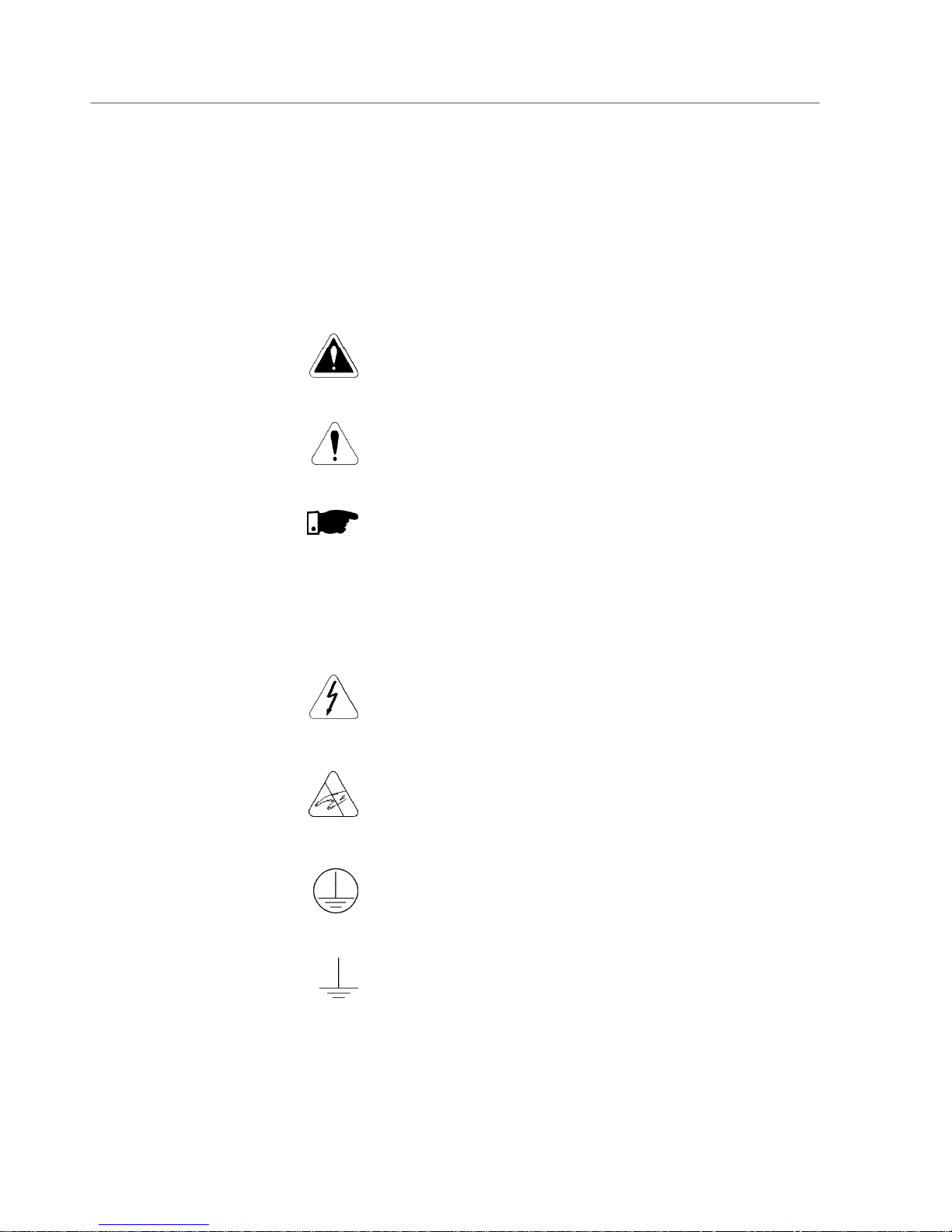
The following Safety Notices will be used in this Manual:
DANGER!
IftherecommendedSafetyInstructionsarenotstrictlyobserved,serious
orfatal injuries of personnel and/or equipmentdamage canoccur.
ATTENTION!
Failure to observe the recommended Safety Procedures can lead to
materialdamage.
NOTE!
ThecontentofthisManualsuppliesimportantinformationforthecorrect
understandingofoperationandproperperformanceof theequipment.
1.1 SAFETYNOTICES
INTHEMANUAL
1.2 SAFETYNOTICESON
THEPRODUCT
Thefollowingsymbolsmaybeattachedtotheproduct,servingasSafety
Notices:
High Voltages
Componentsaresensitivetoelectrostatic discharge.Donot touch
them without following proper grounding procedures.
Mandatory connection to ground protection (PE)
Shield connection to ground
CHAPTER 1
Phone: 800.894.0412 - Fax: 888.723.4773 - Web: www.clrwtr.com - Email: info@clrwtr.com
Page 19
CHAPTER 1 - SAFETY NOTICES
19
NOTE!
In this Manual,qualified personnelare defined as people that are trained to:
1. Install, ground,power-up and operate the SSW-06 according tothis
Manual and the local required safety procedures;
2. Use of safety equipment according to the local regulations;
3. Administer First Aid Treatment.
DANGER!
Always disconnect the main power supply before touching any electrical
component associated to the SSW-06 Soft-Starter.
High voltages and spinningparts (fans) may bepresent even after switching
offthe power supply.Wait atleast3minutes forthecomplete dischargeof the
capacitors.
Always connect the equipment frame to the protection earth (PE) in the
appropriateplacefor this.
ATTENTION!
All electronic boards have components that are sensitive to electrostatic
discharges.Nevertouchanyoftheelectricalcomponentsorconnectorswithout
followingpropergroundingprocedures.If necessarytodoso,touchtheproperly
groundedmetallic frame oruse asuitable groundstrap.
NOTE!
Soft-StarterSSW-06can interfere with other electronicequipment.Inorder to
reduce this interference, adopt the measures recommended in Section 3
“Installation”.
NOTE!
Readthisentiremanualcarefullyandcompletelybeforeinstallingor operating
theSoft-StarterSSW-06.
Do not apply high voltage (High Pot) test on Soft-Starter SSW-06!
If this test is necessary, contact the manufacturer
DANGER!
Only qualified personnel should plan or implement the installation, start-up,
operationandmaintenanceofthisequipment.Personnelmustreviewthisentire
Manualbefore attemptingto install,operateortroubleshootthe SSW-06.
These personnel must follow all safety instructions included in this Manual
and/ordefined by local regulations.
Failuretocomply with these instructionsmayresultin personnel injuryand/or
equipmentdamage.
1.3 PRELIMINARY
RECOMMENDATIONS
Phone: 800.894.0412 - Fax: 888.723.4773 - Web: www.clrwtr.com - Email: info@clrwtr.com
Page 20

20
GENERAL INFORMATION
This chapter defines the contents and purpose of this manual and
describes the main characteristics of the SSW-06 Soft-Starter.
Identification of theSSW-06, receiving and storage requirements are
alsoprovided.
This Manual is divided into 10 Chapters, providing information to the
user on how to receive, install, start-up and operate the Soft-Starter
SSW-06.
Chapter1- Safety Notices;
Chapter2- GeneralInformation;ReceivingandStoringoftheSSW-06;
Chapter3- InformationaboutInstallationandConnectionofthe
Soft-Starter SSW-06 power and control circuit), how to
installoptionsandrecommended drives;
Chapter4- Using the Keypad(HumanMachineInterface - HMI);
Chapter5- Information about runningandstepsto befollowed;
Chapter6- Detailed description of all Soft-StarterSSW-06
programmingparameters;
Chapter7- Information andsuggestions on how to program the
types of control and protections
Chapter8- InformationaboutDiagnosticsandTroubleshooting,
cleaninginstructionsandpreventivemaintenance;
Chapter9- SW-06 Soft-Starteroptionaldevices;
Chapter10- Tables and technical informationabout the powerlines
of the Soft-Starter SSW-06;
ThisManualprovidesinformationforthe correctuseof theSoft-Starter
SSW-06.Duetothevarious functionsoftheSoft-StarterSSW-06many
differentmodesof operation are possible.
As the Soft-Starter SSW-06 can be applied in several ways, it is
impossible to describe here all application possibilities, neither can
WEG assume anyresponsibility when the Soft-Starter SSW-06 is not
used according to this Manual.
No part of this Manual maybe reproduced in any form, without written
permissionfrom WEG.
It is important to notethe Software Version installed in the Soft-Starter
SSW-06,sinceitdefinesthefunctionsandtheprogrammingparameters
ofthe Soft-Starter.This Manualrefers to theSoftwareversion indicated
on the inside cover.For example, the Version1.0X applies to versions
1.00to1.09,where“X”isa variablethatwillchangeduetominorsoftware
revisions.
TheSoftware Versioncan be readthe ParameterP023.
TheSoft-StarterSSW-06 is ahigh performance Drive that permitsthe
start Control of three-phase AC induction motors. The Soft-Starter
SSW-06 prevents mechanical shocks on the load and current peaks
in the supply line.
Amongthe maincharacteristicsofthisproductis itslineandconnection
fault detection capacity thus enabling the customer tochose the best
way of protectinghis the motor,such as:
2.1 ABOUTTHISMANUAL
2.2 SOFTWARE VERSION
2.3 ABOUTTHE
SOFT-STARTER
SSW-06
CHAPTER 2
Phone: 800.894.0412 - Fax: 888.723.4773 - Web: www.clrwtr.com - Email: info@clrwtr.com
Page 21

CHAPTER2 - GENERALINFORMATION
21
Programmableprotections againstlineundervoltageand
overvoltage,andlinephaseimbalance;
Thermal class maybeprogrammedup toClass45for largemotors.
The thermal memory is saved on EEPROM even in case of an
electronic supplyfault.
Specialfunctions such as:
Displayof the number ofhours,runningtime,supplyvoltagephase,
motor current per phase, motor current in amperes, motor current
asa%oftheSoft-StarterSSW-06ratedcurrentandtheratedcurrent
asa %of the motorcurrent, statusof the digital inputs and outputs;
Setting sequence after reset to factory default;
Veryflexibleselectionof start/stopcontroltype,enablingthefollowing
selections: VoltageRamp, Constant Current Limitingor by Ramp,
PumpControland Constant,LinearorQuadraticTorqueControl;
TotallyflexibleTorque Control providingveryhighperformancefor
themost demanding applications;
Possibility of using all digital inputs, digital outputs and analog
outputsas remote PLCvia Fieldbuscommunication;
Possibilityof monitoringthepowersupplyvoltagemeasurementsin
aPLC networkvia Fieldbus communication.
Control Hardware:
Keypad, referred to as the Human Machine Interface (HMI) with
Liquid-CrystalDisplayandeasyprogramming.Faultconditionscan
bedisplayedinseveral languages.
32Bit Microprocessor calculates the True rms voltage and current;
Measurementof thevoltage and current inthe three phases;
Isolated digitalinput for the motor PTC;
Fieldbus boards and RS-485 as options.
Power Hardware:
Compact size;
Power Supply input and output connections:
Models85A to 820A- Input through the top andoutput through the
bottom of the SSW-06.Models 950A to 1400A - Input and output
throughthe bottom.
Easy assembly and maintenance services;
Measurements of heat sink temperature in models 255A to 820A
through two thermostats:One thermostat to switch-on the internal
fansand the otherto monitorover-heating.
Soft-Starter SSW-06 can be coupled to the motor by a standard
connection or an inside delta motor connection without requiring
optionaldevices.
Incorporated By-pass contactor makes the Soft-Starter SSW- 06
(85Ato 820A):
More resistantto supply line oscillations after starting;
Save energy that would be dissipated through the thyristors after
thestart,thus reducingthenumberoffansrequiredfor controlpanel
cooling.
Phone: 800.894.0412 - Fax: 888.723.4773 - Web: www.clrwtr.com - Email: info@clrwtr.com
Page 22
CHAPTER2 - GENERALINFORMATION
22
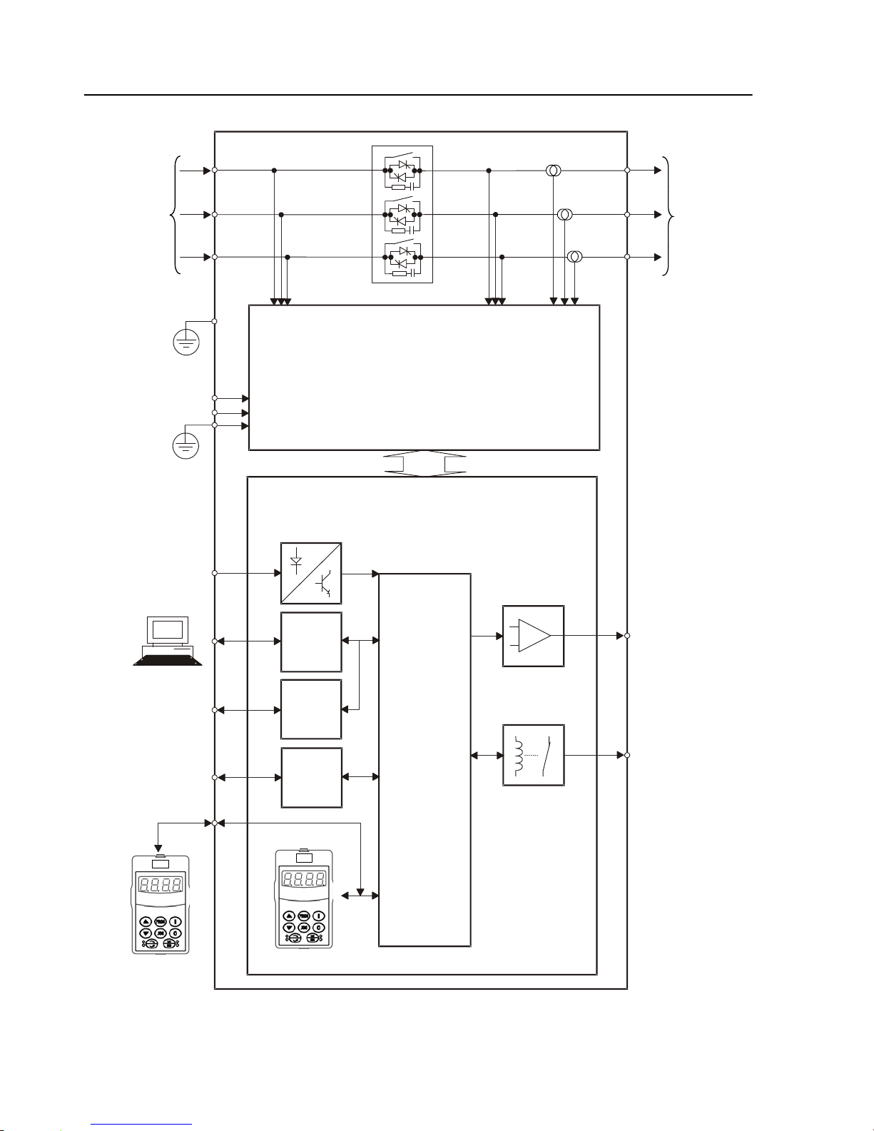
Figure 2.1 - Soft-Starter SSW-06 block diagram
Three-Phase
Power Supply
CONTROL BOARD
Control
Supply
DigitalInputs
Serial
Interface
RS-232
Serial
Interface
(optional)
RS-485
Fieldbus
(optional)
ProfibusDP
DeviceNet
Analog Outputs
DigitalOutputs
Programmable
Analog Outputs
AO1 and AO2
Programmable
DigitalOutputs
RL1...RL3
Programmable
DigitalInputs
DI1...DI6
PC,PLC,MFW,
Super Drive,
ModBUS-RTU
PC,PLC
Three-Phase
Motor
Output
Voltage
Input Voltage
Current
Supply
POWERBOARD
HMI
(Remote)
HMI
(1)
(1)
(1)
CPU
PE
PE
(1) Models 950, 1100 and 1400 do not have an internal By-pass contactor.
Phone: 800.894.0412 - Fax: 888.723.4773 - Web: www.clrwtr.com - Email: info@clrwtr.com
Page 23
CHAPTER2 - GENERALINFORMATION
23
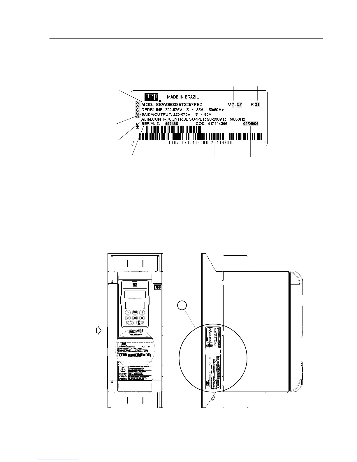
2.4 SOFT-STARTER SSW-06
IDENTIFICATION
Figure 2.2 - Soft-Starter SSW-06 nameplate
LocationofSoft-Starter SSW-06 nameplate:
Figure 2.3 - Detail of the Soft-Starter SSW-06 nameplate
VER DETALHE "A"
X
FRONTAL
A
VISTA DE X
SSW-06 Model
Input Data (Voltage, Number of
Phases, Current, Frequency)
Output Data (Voltage, Number
of Phases, Current)
Control Power Supply Data
(Voltage, Frequency)
SerialNumber
Software
Version
Hardware
Revision
Manufacturing
Date
View Detail A
Identificationnameplate
of the SSW-06
(Internal Cover)
FRONT VIEW VIEWX
WEGItem
Number
Phone: 800.894.0412 - Fax: 888.723.4773 - Web: www.clrwtr.com - Email: info@clrwtr.com
Page 24

CHAPTER2 - GENERALINFORMATION
24
Rated
Output
Current:
0085=85A
0130=130A
0170=170A
0205=205A
0255=255A
0312=312A
0365=365A
0412=412A
0480=480A
0604=604A
0670=670A
0820=820A
0950=950A
1100=1100A
1400=1400A
Thee-phase
Power
Supply
Power Supply
Voltage:
2257=
(220 to 575)V
Manual
Language:
P= portuguese
E=English
S=Spanish
G=German
Human-
Machine
Interface
(Keypad):
Blank =
standard
SI= without
keypad
HOW TO SPECIFY THE SSW-06 MODEL:
SSW-06 0023 T 2257 P O _ _ _ _ _ _ Z
Special
Software:
Blank =
standard
S1=Special
Software
Special
Hardware:
Blank =
standard
H1 = 115V
Ventilation
(Model950A)
H2 = 230V
Ventilation
(Models
950A,1100A
and1400A)
Soft-Starter
SSW-06
WEG Series
End of
Code
NOTES!
The option field (S or O) defines if the Soft-Starter SSW-6 is a standard version or if it is equipped with any optional devices. If the standard version is
required, the code ends here. The model number alwayshas the letter Z at the end. For example:
SSW060085T2257ESZ = StandardSoft-StarterSSW-06 with current of 85Aand 220V to 575V with Manual in English.
If there are accessories, the spaces must be filled out in the correct sequence until the code ends with the letter zero.
Thestandard productis defined as described here:
Degreeof protection:IP00from 85Ato1400A
Human-Machine-Interface: HMI-SSW06 (withLCDandLEDdisplays).
Obs.: The communication kits are optional, see chapter 9.
Options:
S=Standard
O=with options
Phone: 800.894.0412 - Fax: 888.723.4773 - Web: www.clrwtr.com - Email: info@clrwtr.com
Page 25

CHAPTER2 - GENERALINFORMATION
25
2.5 RECEIVINGAND
STORAGE
The SSW-06 is supplied in packaging according to the model:
-Models 85A to 205A in a cardboard box;
-Models255A to 365Ain a cardboard boxover a woodenbox;
-Models 412A to 1400A ina woodenbox.
The outside of the packing container has a nameplate that is identical
tothaton the Soft-StarterSSW-06.Pleasecheck if thenameplatedata
matches the ordered data.
Themodels upto 205A must be placedand opened on atable with the
helpof two or more people,open thebox, remove thefoam protection
andremoveSoft-StarterSSW-06.
Themodels up to 205Amust be placed and openedonatablewiththe
helpof twoor more persons.
Open the box, remove the foam protection and remove Soft-Starter
SSW-06 with the help of two or more persons.
Models greater than 255A must be openedon the floor. Open the box
and,removetheboltsthatfastentheSoft-StarterSSW-06 onthepallet.
The Soft-Starter SSW-06 must be handled with a hoist.
Check if:
The Soft-Starter SSW-06 nameplate data matches the purchase
order;
Theequipmenthas not beendamagedduring transportation.If any
problem is detected, contact the carrier immediately.
If the Soft-StarterSSW-06is notto be installedimmediately, storeit
within its original cardboard boxin a clean and dry room (Storage
temperaturesbetween - 10°C(14ºF)and65°C(149ºF)).
Phone: 800.894.0412 - Fax: 888.723.4773 - Web: www.clrwtr.com - Email: info@clrwtr.com
Page 26
26
CHAPTER 3
3.1 MECHANICAL
INSTALLATION
INSTALLATION AND CONNECTION
Thischapterdescribestheelectricandmechanic installationprocedures
of the SSW-06 Soft-Starters. The orientations and suggestions must
befollowedfor correct productfunctioning.
3.1.1Environment Conditions
The location of the Soft-Starter SSW-06 installation is an important
factorto assure good performance andhigh product reliability.
Forproperinstallationof theSSW-06Soft-Starter,wemakethefollowing
recommendations:
Avoiddirectexposuretosunlight,rain,excessivehumidityor marine
environment;
Gases or explosive or corrosiveliquids;
Excessive vibration, dust or metallic and/or oil particles in the air.
Allowed Environment Conditions:
Temperature: 0ºC to 55ºC (32ºF to 131ºF) – Rated conditions for
models 85A to 820A;
0ºC to 40ºC (32ºF to 104ºF) – Ratedconditions for models950A to
1400A.
2%CurrentreductionforeachdegreeCelsiusabovethespecification
in the ratedconditions.
RelativeAir Humidity:5% to 90%, non-condensing.
MaximumAltitude:1000m ( 3,300 ft) - rated conditions.
From1000mto4000m(3,300ftto13,200ft)-with1%currentreduction
foreach100m(330ft)above1000m(3,300ft).
Degree of Pollution:2 (accordingto UL508).
Water,condensationor conductivedust/particlesare notallowedin
the air.
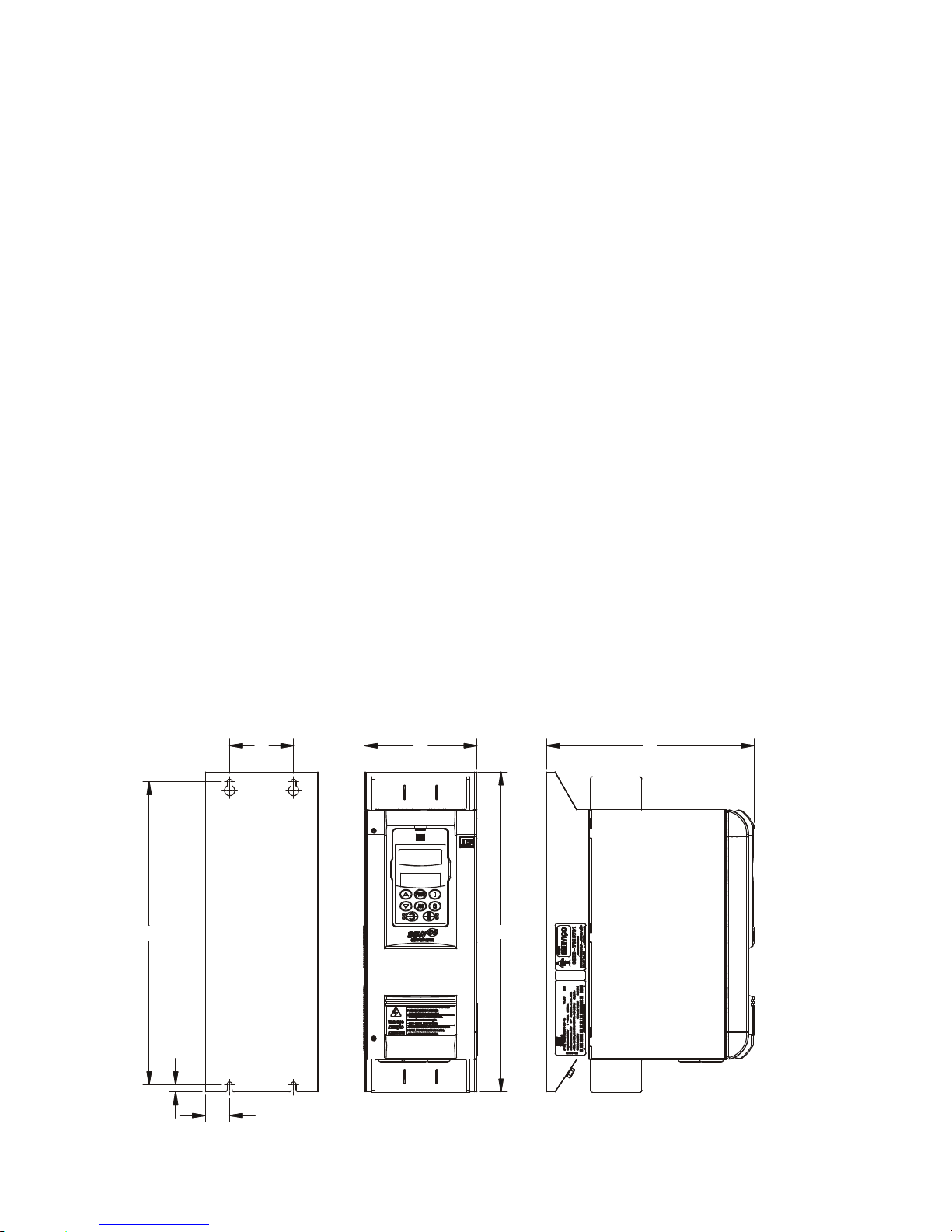
3.1.2 Dimensionsof the
Soft-StarterSSW-06
ExternaldimensionsandmountingholesfollowFigure3.1andTable3.1.
Figure 3.1 - Dimensional Drawings of the Soft-Starter SSW-06
A
W
D
C
B
D2
H
Phone: 800.894.0412 - Fax: 888.723.4773 - Web: www.clrwtr.com - Email: info@clrwtr.com
Page 27
CHAPTER3 - INSTALLATIONANDCONNECTION
27
Model
Height Width Depth.
A B C D2
Mounting
Weight
Degree of
H W D
mm mm mm mm
screw
Kg
Protection
mm mm mm
(in) (in) (in) (in)
mm
(lb)
(in) (in) (in)
(in)
SSW-06.0085 370 132 244 75 350 28.5 8.5 M5 8.5
IP00
SSW-06.0130 (14.57) (5.20) (9.61) (2.95) (13.78) (1.12) (0.33) (1/4") (18.74)
SSW-06.0170 440 223 278 150 425 36.5 5.9 M6 18.5
SSW-06.0205 (17.32) (8.78) (10.94) (5.91) (16.73) (1.44) (0.23) (1/4") (40.79)
SSW-06.0255 550 370 311 200 527.5 84.8 10 M6 39.5
SSW-06.0312 (21.65) (14.57) (12.24) (7.87) (20.77) (3.34) (0.39) (1/4") (87.08)
SSW-06.0365
SSW06.0412 650 369.5 347 200 627.5 84.75 11.25 M6 55.0
SSW06.0480 (25.59) (14.55) (13.67) (7.87) (24.7) (3.33) (0.44) (1/4") (121.27)
SSW06.0604
SSW06.0670 795 540 357.12 250 775 145 10 M8 120.0
SSW06.0820 (31.3) (21.26) (14.06) (9.84) (30.51) (5.71) (0.39) (5/16") (264.60)
SSW06.0950 894.5 568.2 345.15 400 810 84.1 10 M8 107.0
(35.22) (22.37) (13.59) (15.75) (31.89) (3.31) (0.39) (5/16") (235.93)
SSW06.1100 1234.8 685 432.94 500 1110 92.5 15 M8 217.5
SSW06.1400 (48.61) (26.97) (17.04) (19.68) (43.7) (3.64) (0.59) (5/16") (479.59)
Table 3.1 - Installation Data with dimensions in mm (in)
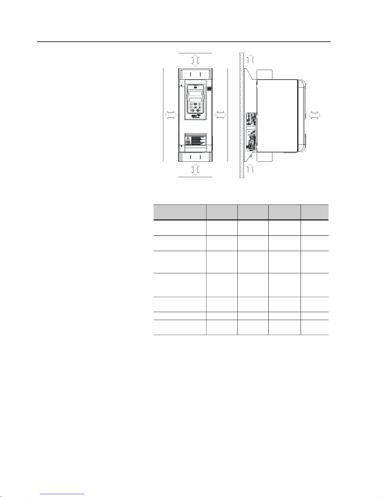
At least the spaces around the soft-starter must be left open for the
installation of the SSW-06 Soft-Starter, according to Figure 3.2, as
follows.The dimensions of each space are described intable 3.2.
InstalltheSoft-Starter SSW-06inthe verticalpositionaccordingtothe
followingrecommendations:
1) Install the SSW-06 Soft-Starteron a flat surface;
2)Donot place heat sensitivecomponentsontopof theSSW-06 SoftStarter;
ATTENTION!
If the Soft-Starters are installed one next to the other, use minimum
distance B.
WhenaSoft-Starterisinstalledontopof another,useminimum distance
A+Candavoidto the Soft-Starterabovethe hotairthatcomesfrom the
Soft-Starterbelow.
ATTENTION!
Foreseeindependentconduits or electroducts for physicallyseparating
the signal, control and power conductors (see item 3.2, electrical
installation).
3.1.3 Positioning / Fixing
Phone: 800.894.0412 - Fax: 888.723.4773 - Web: www.clrwtr.com - Email: info@clrwtr.com
Page 28
CHAPTER3 - INSTALLATIONANDCONNECTION
28
Figure 3.2 - Free spaces for cooling
CAY
B
B
Table 3.2 - Recommended free spaces
Air Flow Outlet
Air Flow Inlet
A
mm(in)
150 (5.90)
150 (5.90)
150 (5.90)
150 (5.90)
150 (5.90)
150 (5.90)
150 (5.90)
Model
SSW-06.0085
SSW-06.0130
SSW-06.0170
SSW-06.0205
SSW-06.0255
SSW-06.0312
SSW-06.0365
SSW-06.0412
SSW-06.0480
SSW-06.0604
SSW-06.0670
SSW-06.0820
SSW-06.0950
SSW-06.1100
SSW-06.1400
B
mm(in)
30 (1.18)
30 (1.18)
30 (1.18)
30 (1.18)
30 (1.18)
30 (1.18)
100 (3.93)
C
mm(in)
150 (5.90)
150 (5.90)
150 (5.90)
150 (5.90)
150 (5.90)
150 (5.90)
150 (5.90)
Y
mm(in)
50 (1.96)
50 (1.96)
50 (1.96)
50 (1.96)
50 (1.96)
50 (1.96)
50 (1.96)
WhentheSoft-StarterSSW-06areinstalledinpanelsor closedmetallic
boxes, adequate cooling is required to ensure that the temperature
aroundtheinverterwillnotexceedthemaximum allowedtemperature.
See Dissipated Power in the table 3.4.
3.1.3.1Mounting insideaPanel
Phone: 800.894.0412 - Fax: 888.723.4773 - Web: www.clrwtr.com - Email: info@clrwtr.com
Page 29
CHAPTER3 - INSTALLATIONANDCONNECTION
29
Use the minimum recommended panel dimensions and its cooling
requirements:
Table 3.3 - Panel Dimensions and Cooling Requirements
Table 3.4 - Power losses for panel fan dimensioning
NOTE!
Thefans abovearerecommended fordutiesof 10starts/hourwith3 x In
oftheSoft-Starterduring30s.
Power Losses
In the
eletronics
Fan Power
Total Power losses in
the SCRs in Full
Voltage
Average power
losses-10 starts/h
3xln@30s
Total average power
losses-10 starts/h
3xIn@30s
Model
W W W W W
SSW-06.0085 33 - 0 = By-pass 76.5 109.5
SSW-06.0130 33 - 0 = By-pass 117.0 150.0
SSW-06.0170 33 - 0 = By-pass 153.0 186.0
SSW-06.0205 33 - 0 = By-pass 184.5 217.5
SSW-06.0255 33
58
528mA@110Vac
264mA@220Vac
0 = By-pass 229.5 320.5
SSW-06.0312 33
58
528mA@110Vac
264mA@220Vac
0 = By-pass 280.8 371.8
SSW-06.0365 33
58
528mA@110Vac
264mA@220Vac
0 = By-pass 328.5 419.5
SSW-06.0412 33
58
528mA@110Vac
264mA@220Vac
0 = By-pass 370.8 461.8
SSW-06.0480 33
58
528mA@110Vac
264mA@220Vac
0 = By-pass 432.0 523.0
SSW-06.0604 33
58
528mA@110Vac
264mA@220Vac
0 = By-pass 543.6 634.6
SSW-06.0670 33
87
396mA@110Vac
972mA@220Vac
0 = By-pass 603.0 723.0
SSW-06.0820 33
87
396mA@110Vac
1391mA@220Vac
0 = By-pass 738.0 858.0
SSW-06.0950 33
160
727mA@110Vac
955mA@220Vac
3420 427.5 3898.0
SSW-06.1100 33
210
955mA@220Vac 3960 495.0 4533.0
SSW-06.1400 33 210 955mA@220Vac 5040 630.0 5703.0
CoolingCFM
(m3/min)
-
-
-
-
-
1757.30 (49.80)
1757.30 (49.80)
2648.44 (75.00)
Model
SSW-06.0085
SSW-06.0130
SSW-06.0170
SSW-06.0205
SSW-06.0255
SSW-06.0312
SSW-06.0365
SSW-06.0412
SSW-06.0480
SSW-06.0604
SSW-06.0670
SSW-06.0820
SSW-06.0950
SSW-06.1100
SSW-06.1400
PanelDimensions
Width Hiegth Depth
mm(in) mm (in) mm(in)
600 1200 400
(23.62) (47.24) (15.75)
600 (23.62) 1600 (63.00) 600 (23.62)
600 2000 600
(23.62) (78.74) (23.62)
600 2000 600
(23.62) (78.74) (23.62)
800 2000 600
(31.50) (78.74) (23.62)
800 (31.50) 2000 (78.74) 600 (23.62)
800 2000 600
(31.50) (78.74) (23.62)
Phone: 800.894.0412 - Fax: 888.723.4773 - Web: www.clrwtr.com - Email: info@clrwtr.com
Page 30
CHAPTER3 - INSTALLATIONANDCONNECTION
30
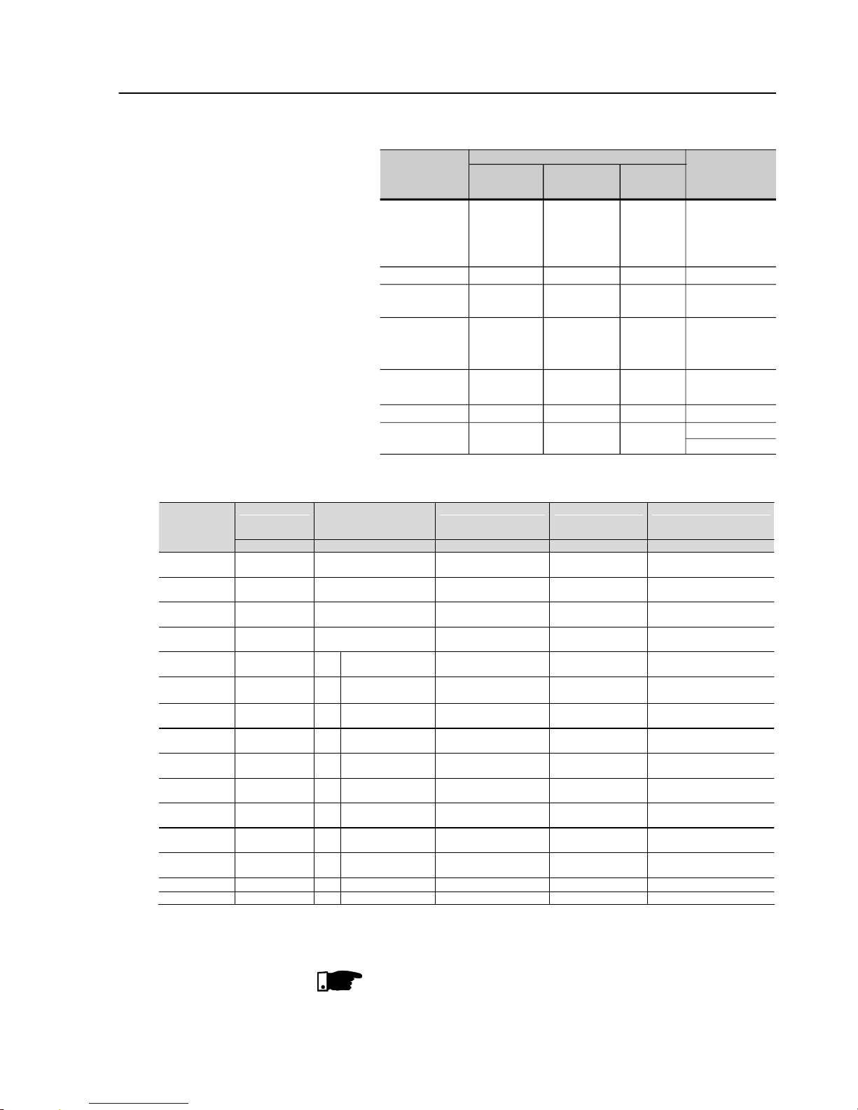
Thetotal power lossescan be determinedthroughthe equationbelow:
where:
Pe = power losses at the electronics (W)
tc = working cycle time (s)
Ip = start current (A)
tp = start time (s)
In = current at rated duty(A), with By-pass In=0
tr = rated duty time (Full Voltage) (s)
Ptd = total power losses (W)
Figure 3.3 - Soft-Starter SSW-06 working cycle for
power loss determination
Ptd
tc
trInVtpIpVtcPe
)32.1()32.1()(
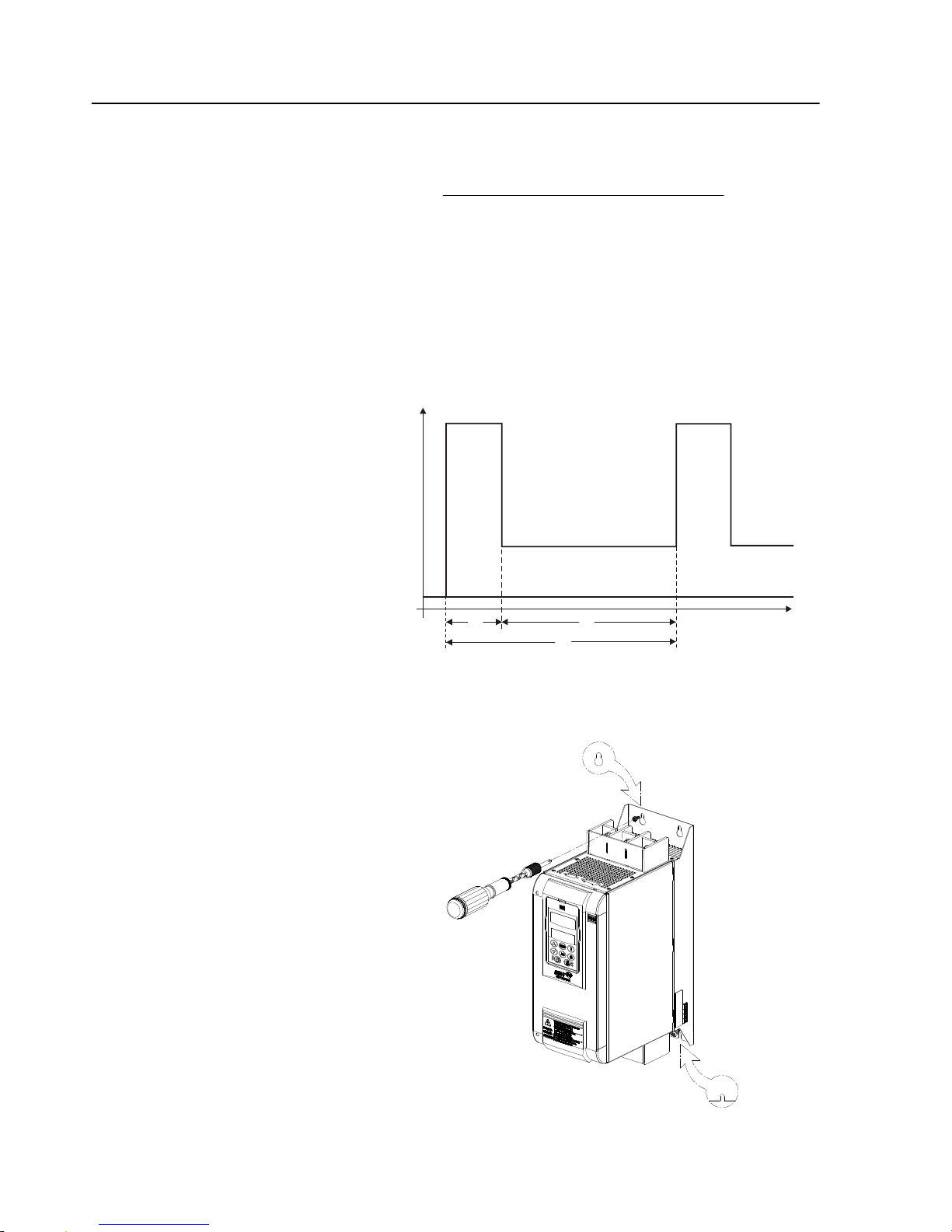
The figure 3.4 shows the installation of the Soft-StarterSSW-06 on a
mountingplate.
3.1.3.2 MountingonaSurface
Figure 3.4 - Mounting procedures for the SSW-06 on a flat surface
P(W)
I(A)
Ip
0
tp
tr
tc
Pe
In
t(s)
Phone: 800.894.0412 - Fax: 888.723.4773 - Web: www.clrwtr.com - Email: info@clrwtr.com
Page 31

CHAPTER3 - INSTALLATIONANDCONNECTION
31
First install and partiallytighten the mountingbolts, inagreement with
figures3,1 and 3,4and table3.1,then installthe Soft- StarterSSW-06
and tighten the mouthing bolts.
Figure 3.5 - Procedures for HMI removal and front cover
opening of the control connections
3.2 ELECTRICAL
INSTALLATION
DANGER!
TheSoft-StarterSSW-06cannotbeusedasanemergencystopdevice.
DANGER!
Be sure that the AC input power is disconnected before making any
terminalconnections.
ATTENTION!
The information belowwill be a guide to achieve a proper installation.
Also follow all applicable local standards for electrical installations.
Provideatleasta 0.25m(10in)spacebetweenthe sensitiveequipment
andwiring from the Soft-Starter SSW-06, andthe cables betweenthe
Soft-StarterSSW-06andthemotor.Example:PLC,temperaturewiring,
thermocouple cables, etc.
Figure 3.6 - Standard power/grounding connections
R/1L1
S/3L2
T/5L3
Circuit-breaker
Line
Fuses
T
S
R
U/2T1 PEV/4T2 W/6T3
Phone: 800.894.0412 - Fax: 888.723.4773 - Web: www.clrwtr.com - Email: info@clrwtr.com
Page 32

CHAPTER3 - INSTALLATIONANDCONNECTION
32
The power connection terminals can be of different sizes and
configurations,dependingontheSoft-StarerSSW-06modelasshown
in Figures 3.8 and 3.9.
Terminals:
R / 1L1, S / 3L2and T / 5L3 :AC supply line
U / 2T1, V / 4T2 and W /6T3: Motor connection.
3.2.1 PowerTerminals
U/2T1 V/4T2 W/6T3 PE
R/1T1 S/3T2 T/5T3
PE
Figure 3.7 - Power/Grounding connections for inside delta motor
connection
R/1L1
S/3L2
T/5L3
Circuit-breaker
Line
Fuses
T
S
R
*Dimensions in mm (in)
a) Models: 85A and 130A
Figura 3.8 a) - Maximum tightening torque for power connection
79.5
(3.13)
25
(0.98)
24.5
(0.96)
20
(0.79)
30.6
(1.20)
20
(0.79)
39
(1.54)
39
(1.54)
27
(1.06)
InputTerminal
Power
Stell M6 (6x)
OutputTerminal
Power
79.5
(3.13)
Phone: 800.894.0412 - Fax: 888.723.4773 - Web: www.clrwtr.com - Email: info@clrwtr.com
Page 33

CHAPTER3 - INSTALLATIONANDCONNECTION
33
*Dimensions in mm (in)
b) Models: 170A and 205A
Figura 3.8 b) c) – Power terminals
55.3
(2.18)
56.3
(1.30)
56.3
(1.30)
39.5
(1.56)
InputTerminal
Power
OutputTerminal
Power
40
(1.57)
Stell M8 (6x)
20
(0.79)
29.4
(1.16)
112
(4.41)
20
(0.79)
132
(5.20)
35
(1.38)
30
(1.18)
80
(3.15)
59.8
(2.35)
41
(1.30)
63.5
(2.50)41(1.30)
63.5
(2.50)
41
(1.30)
InputTerminal
Power
OutputTerminal
Power
Stell M10 (12x)
179.5
(7.07)
179.5
(7.07)
25
(0.98)
25
(0.98)
*Dimensions in mm (in)
c) Models: 225A, 312A, 365A, 412A, 480A and 604A
Phone: 800.894.0412 - Fax: 888.723.4773 - Web: www.clrwtr.com - Email: info@clrwtr.com
Page 34

CHAPTER3 - INSTALLATIONANDCONNECTION
34
d) Models: 670A and 820A
23.9
(0.94)
120
(4.72)
95
(3.74)
60
(2.36)
85
(3.35)
InputTerminal
Power
OutputTerminal
Power
Stell M12 (12x)
214.3
(8.44)
25
(0.98)
25
(0.98)
60
(2.36)
85
(3.35)
60
(2.36)
29.7
(1.17)
214.3
(8.44)
*Dimensions in mm (in)
e) Models: 950A
*Dimensions in mm (in)
22
(0.87)
66.1
(2.60)
51.7
(2.04)
49.5
(1.95)
53.4
(2.10)
156
(6.14)
22
(0.87)
156
22
(0.87)
50
(1.97)
Output Bus Bar
Power
22
(0.87)
14
(0.55)
212.2
(8.35)
98.8
(3.89)
49.7
(1.96)
110.3
(4.34)
49.7
(1.96)
100
(3.94)
110.3
(4.34)
49.7
(1.96)
Input Bus Bar
Power
40
(1.57)
20
(0.79)
Figura 3.8 d) e) – Power terminals
Stell M12 (12x)
Stell M10 (6x)
Phone: 800.894.0412 - Fax: 888.723.4773 - Web: www.clrwtr.com - Email: info@clrwtr.com
Page 35

CHAPTER3 - INSTALLATIONANDCONNECTION
35
f) Models: 1100Aand 1400A
*Dimensions in mm (in)
50
(1.97)
89
(3.50)
60.3
(2.37)
58
(2.28)
104.5
(4.11)
163
(6.42)
100
(3.94)
Output Bus Bar
Power
262
(10.31)
129.4
(5.09)
40
(1.57)
158
(6.22)
40
(1.57)
120
(4.72)
158
(6.22)
40.7
(1.57)
Input Bus Bar
Power
40
(1.57)
20
(0.79)
Stell M12 (12x)
50
(1.97)
Stell M12 (12x)
163
(6.42)
50
(1.97)
40
(1.57)
20
(0.79)
Figura 3.8 f) – Power terminals
Table 3.5 - Maximum tightening Torque for power connection
Bolt
M6
(1/4")
M8
(5/16")
M10
(3/8")
M10
M12
M12
M12
SSW-06
SSW-06.0085
SSW-06.0130
SSW-06.0170
SSW-06.0205
SSW-06.0255
SSW-06.0312
SSW-06.0365
SSW-06.0412
SSW-06.0480
SSW-06.0604
SSW-06.0670
SSW-06.0820
SSW-06.0950
SSW-06.1100
SSW-06.1400
Torque
Nm(lb.in)
8.3
(74.38)
19
(166.25)
37
(328.12)
37
61
61
61
Bolt
M6
(1/4")
M6
(1/4")
M10
(3/8")
M10
M10
M10
M10
Torque
Nm(lb.in)
8.3
(74.38)
8.3
(74.38)
37
(328.12)
37
37
37
37
Line / Motor Grounding
Phone: 800.894.0412 - Fax: 888.723.4773 - Web: www.clrwtr.com - Email: info@clrwtr.com
Page 36

CHAPTER3 - INSTALLATIONANDCONNECTION
36
3.2.2 Locationof the Power/Grounding,
ControlConnections andFanVoltageSelection
Figura 3.9 a) to e) - Location of the Power/ Grounding, Control Connections and Fan Voltage Selection
a) Models 85A and 130A b) Models 170A and 205A c) Models 255A ,312A and 365A
d) Models 412A,480A and 640A
e) Models 670A and 820A
Grounding
Grounding
Grounding
IntputTerminal
Power
IntputTerminal
Power
IntputTerminal
Power
Power
Control
Power
Control
FanSupply
Control
Power
Fan
VoltageSelection
110/220V
OutputTerminal
Power
OutputTerminal
Power
OutputTerminal
Power
Control
Power
FanSupply
Fan
VoltageSelection
110/220V
OutputTerminalPower
Intputterminal
Power
Grounding
Control
Power
FanSupply
Fan
VoltageSelection
110/220V
Output TerminalPower
Intputterminal
Power
Grounding
Phone: 800.894.0412 - Fax: 888.723.4773 - Web: www.clrwtr.com - Email: info@clrwtr.com
Page 37

CHAPTER3 - INSTALLATIONANDCONNECTION
37
Figure 3.9 f) and g) – Location of the Power, Grounding, Control and Selection Connections
Control
Power
FanSupply
IntputTerminal
Power
OutputTerminal
Power
Control
Power
FanSupply
OutputTerminal
Power
IntputTerminal
Power
f) Model 950A
g) Models 1100Ato 1400A
Grounding
Grounding
Phone: 800.894.0412 - Fax: 888.723.4773 - Web: www.clrwtr.com - Email: info@clrwtr.com
Page 38

CHAPTER3 - INSTALLATIONANDCONNECTION
38
3.2.3 RecommendedPower/
GroundingCables
Thedescribed specificationsin tables 3,6 and 3,7 arevalid only for the
followingconditions:
Copper wires with PVC 70°C (158ºF) PVC insulation, for room
temperature of 40°C (104ºF) , installed in perforated and nonagglomeratedconduits
Naked or silvercoaredcopperbusbarswithroundedges and radius
equal to 1 mm with room temperature of 40°C (104ºF) and bus
temperatureof 80°C (176ºF).
Obs.: When external By-pass contactors are applied, use the same
cablesor busbar applied for the motor connection.
NOTE!
Forcorrect cabledimensioning,consider the installationconditionand
themaximum permitted line voltagedrop.
Current
100% In
(A)
85
130
170
205
255
312
365
412
480
604
670
820
950
1100
1400
Model
SSW-06.0085
SSW-06.0130
SSW-06.0170
SSW-06.0205
SSW-06.0255
SSW-06.0312
SSW-06.0365
SSW-06.0412
SSW-06.0480
SSW-06.0604
SSW-06.0670
SSW-06.0820
SSW-06.0950
SSW-06.1100
SSW-06.1400
Cables
(mm²)
25
50
70
95
120
185
240
240
300
2 x 150
2 x 185
2 x 240
2 x 300
4 x 150
4 x 185
Bus
(mmxmm)
12 x 2
20 x 3
20 x 3
20 x 3
25 x 5
25 x 5
25 x 5
30x5
40x5
40x5
40x10
40x10
50x10
60x10
80x10
Grounding
Cables
(mm²)
10
25
35
50
70
95
120
120
150
150
185
240
300
2 x 150
2 x 185
Table 3.6 - Minimum specification of cables and busbars for standard
connection
Phone: 800.894.0412 - Fax: 888.723.4773 - Web: www.clrwtr.com - Email: info@clrwtr.com
Page 39

CHAPTER3 - INSTALLATIONANDCONNECTION
39
Current
100% In
(A)
147
225
294
355
441
540
631
713
831
1046
1160
1420
1645
1905
2424
Model
SSW-06.0085
SSW-06.0130
SSW-06.0170
SSW-06.0205
SSW-06.0255
SSW-06.0312
SSW-06.0365
SSW-06.0412
SSW-06.0480
SSW-06.0604
SSW-06.0670
SSW-06.0820
SSW-06.0950
SSW-06.1100
SSW-06.1400
Line
Cables
(mm²)
70
95
150
185
300
400
500
2 x 185
2 x 240
4 x 120
4 x 150
4 x 185
4 x 240
4 x 300
4 x 500
Line
Bus
(mmxmm)
20 x 3
20 x 3
25 x 5
25 x 5
30 x 5
40 x 5
60 x 5
40x10
40x10
50x10
60x10
80x10
100x10
120x10
160x10
Motor
Cables
(mm²)
25
50
70
95
120
185
240
240
300
2 x 150
2 x 185
2 x 240
2 x 300
4 x 150
4 x 185
Motor
Bus
(mmxmm)
12 x 2
20 x 3
20 x 3
20 x 3
25 x 5
25 x 5
25 x 5
30x5
40x5
40x5
40x10
40x10
50x10
60x10
80x10
Grounding
Cables
(mm²)
10
25
35
50
70
95
120
120
150
150
185
240
300
2 x 150
2 x 185
Table 3.7 - Recommended cables for inside delta motor connection
DANGER!
TheAC inputvoltagemust becompatiblewiththeSoft-StarterSSW-06
ratedvoltage.
DANGER!
Providepowersupplydisconnectingswitch.This disconnectingswitch
must disconnect the AC input voltage from the Soft-Starter SSW-06,
always when required(forinstanceduringmaintenanceservices).
DANGER!
If a disconnect switch or a contactor is inserted in the motor supply
line,DO NOT operate these deviceswithrunning motor or when
Soft-Starter SSW-06 is enabled.
ATTENTION!
Controlof overvoltageinthe line thatsupplies the Soft-Startermustbe
madeusingsurgeprotectionwithavoltageof680 Vac(phasetophase
connection) and energy absorption capacity of 40 joules (for models
from 85Ato 205A) or 80 joules (for models from 255A to 1400A).
NOTE!
Use wire sizing and fuses as recommended in Table 3.6, 3.7 and 3.9.
The connector tighteningtorque is as indicated in Table 3.5. Use 70ºC
(158ºF)copper wiresonly.
3.2.4 Connectionof the Power
Supplytothe Soft-Starter
Phone: 800.894.0412 - Fax: 888.723.4773 - Web: www.clrwtr.com - Email: info@clrwtr.com
Page 40

CHAPTER3 - INSTALLATIONANDCONNECTION
40
The SSW-06 Soft-Starter is suitable to use in a circuit capable of
supplying at most the current (symmetric Arms) established for each
model, and, respective voltage (V) according to table 3.8. This, when
protected by highspeed semiconductor fuses.
3.2.4.1 Power SupplyCapacity
Standard
Connection
220-575V (kA)
10
10
10
10
18
18
18
30
30
42
42
85
85
85
85
Model
SSW-06.0085
SSW-06.0130
SSW-06.0170
SSW-06.0205
SSW-06.0255
SSW-06.0312
SSW-06.0365
SSW-06.0412
SSW-06.0480
SSW-06.0604
SSW-06.0670
SSW-06.0820
SSW-06.0950
SSW-06.1100
SSW-06.1400
Inside - Delta
Connection
220-575V (kA)
10
18
18
18
30
30
42
42
42
85
85
85
100
100
125
Table 3.8 - Maximum current capacity of the power supply
The fuses to beused in the inputmust be high speed semiconductor
fuses with l2t lower of equal to 75% of the SCR value indicated above
(A2s).
These fuses will protect the SRCs in case of a short-circuit. Normal
fuses can also be used, instead of the high speed, which will protect
the installationfrom short-circuits, but the SCRs will not be protected.
3.2.4.2 RecommendedFuses
Standard
Connection
In (A)
200
250
450
500
500
500
550
700
900
900
900
1400
1600
1600
2000
Model
SSW-06.0085
SSW-06.0130
SSW-06.0170
SSW-06.0205
SSW-06.0255
SSW-06.0312
SSW-06.0365
SSW-06.0412
SSW-06.0480
SSW-06.0604
SSW-06.0670
SSW-06.0820
SSW-06.0950
SSW-06.1100
SSW-06.1400
Delta - Inside
Connection
In (A)
315
350
500
550
700
700
700
1250
1400
1600
1600
2000
2200
2500
3000
I²t of the SCR
(kA²s)
80
84
245
320
238
238
320
1452
4250
4250
4250
4250
14000
14000
15125
Table 3.9 - Recommended Fuses.
Phone: 800.894.0412 - Fax: 888.723.4773 - Web: www.clrwtr.com - Email: info@clrwtr.com
Page 41

CHAPTER3 - INSTALLATIONANDCONNECTION
41
DANGER!
Powerfactor correctioncapacitorsshouldneverbeinstalledat theoutput
of the Soft-Starter SSW-06 (U / 2T1, V / 4T2 and W /6T3).
ATTENTION!
Fortheprotectionsbasedonthe current readingand indicationto work
correctly, in case of overloadprotection, the rated current of the motor
cannot be lower than30% of the ratedcurrent of the SSW-06
Soft-Starter.
It is not recommended to use motors with the load working duty lower
than 50% of its rated current.
NOTE!
Use wire sizing and fuses as recommended in Table 3.6, 3.7 and 3.9.
The connector tighteningtorque is as indicated in Table3.5. Use 70ºC
(158ºF)copper wiresonly.
NOTE!
Soft-Starter SSW-06 is provided with anelectronic protection against
motor overload. This protection must be set according to the specific
motor. When several motors are connected the same Soft-Starter
SSW-06, use individual overload relaysfor each motor.
The SSW-06 Soft-Starter can be connected to the motor in two
ways, according to 3.2.5.1 and 3.2.5.2.
3.2.5 Connectionofthe
SSW-06Soft-Starter
tothe motor
3.2.5.1 StandardThree-Wire
Connection
(P150=0=Inactive)
The standard 3 wires connection allows the SSW-06 Soft-Starter line
current to be equal to the motor current.
Figure 3.10 - Soft-Starter SSW-06 with standard connection
1/U1
4/U2
2/V1
5/V2
6/W2
3/W1
2/V1
5/V2
1/U1
4/U2
6/W2
3/W1
R
S
T
N
PE
R
S
T
N
PE
R
U
S
V
W
T
R
U
S
V
T
W
Phone: 800.894.0412 - Fax: 888.723.4773 - Web: www.clrwtr.com - Email: info@clrwtr.com
Page 42

CHAPTER3 - INSTALLATIONANDCONNECTION
42
3.2.5.2 Inside Delta
MotorConnection
(P150=1=Active)
Inthis kind ofconnection,the SSW-06 Soft-Starterlinecurrent is equal
to approximately58% of the rated current of the motor.
Figure 3.11 - Soft-Starter SSW-06 Inside Delta Motor Connection
Figure 3.12 - Soft-Starter SSW-06 Inside Delta Motor Connection - motor
with double delta series connected.
S
S
V
W
R
R
T
T
U
R
S
T
N
PE
2/V1
5/V2
6/W2
3/W1
8/V3
11/V4
7/U3
10/U4
12/W4
9/W3
1/U1
4/U2
Figure 3.13 - Soft-Starter SSW-06 Inside Delta Motor Connection - motor
with double delta parallel connected.
1/U1
4/U2
2/V1
5/V2
6/W2
3/W1
R
S
T
N
PE
S
S
V
W
R
R
T
T
U
2/V1
5/V2
6/W2 3/W1
8/V3
11/V4
12/W4 9/W3
7/U3
10/U4
1/U1
4/U2
R
S
T
N
PE
R
S
W
T
S
R
T
V
U
Phone: 800.894.0412 - Fax: 888.723.4773 - Web: www.clrwtr.com - Email: info@clrwtr.com
Page 43

CHAPTER3 - INSTALLATIONANDCONNECTION
43
ATTENTION!
Fortheconnectioninside the delta of the motor,themotor must have a
deltaconnection in the desired voltage.
NOTES!
1) In the motor inside delta connection, the SSW-06 Soft-Starter
connection cables to the power supply, fuses and/or the main
contactor must support the rated current of the motor. The motor
connection cables to the Soft-Starter and/or the external By-pass
contactor connection must support 58% of the rated current of the
motor.
2) Due to the presence of high currents and large cable sizes
requirements, we also recommend the use of copper busbars for
connecting the Soft-StarterSSW-06 to the power supply.
3) During the start of the motor current in relation to the Soft-Starteris
1.50. However in full voltage condition (after the start time of the
motor) the current relation is 1.73.
ATTENTION!
Payattentiontotheconnectionofthemotortothe SSW-06Soft-Starter,
respecttheconnectiondiagrams shown in thefiguresaboveaccording
to the type of motor windings. If it is necessary to change the motor
speeddirection,onlyinverttheSSW-06 Soft-Starterconnectionstothe
powersupply.
Maintainthe electronics turned off during the connectionchanges.
ATTENTION!
Ensurecorrectsettingof Parameter P150 before the motor is switched
ON.Soft-StarterSSW-06maybedamaged,whenthisparametersetting
is not correct
P150 Action
0 (Inactive) Soft-Starter SSW-06 with standard connection to motor
1 (Active) Soft-Starter SSW-06 inside of the delta motor connection
DANGER!
TheSoft-Starter SSW-06 must begroundedfor safetypurposes(PE).
Theearthorgroundconnectionmust complywiththelocalregulations.
Forgrounding,usecables withcross sectionasindicatedinTable 3.6.
Make the ground connection to a grounding bar or to the general
groundingpoint (resistance 10 ohms).
DANGER!
TheACinput for the Soft-StarterSSW-06 must be grounded.
DANGER!
Donotusetheneutralconductorforgroundingpurpose.Useaspecific
groundconductor.
ATTENTION!
Do notshare the ground wiring with otherequipment that operate with
highcurrents(forinstance,highvoltagemotors,weldingmachines,etc).
Whenmorethanoneself-starterSSW-06used,see3.14figure.
3.2.6 GroundingConnections
Table 3.10 - Connection of the Soft-Starter to the motor
Phone: 800.894.0412 - Fax: 888.723.4773 - Web: www.clrwtr.com - Email: info@clrwtr.com
Page 44

CHAPTER3 - INSTALLATIONANDCONNECTION
44
EMI – Electromagnetic interference:
TheSoft-StarterSSW-06isdeveloped to beusedinindustrialsystems
(ClassA) as per NormEN60947-4-2.
It’s necessary to have a distance of 0,25m (10in) between the SoftStarter SSW-06and the cablesbetweentheSoft-StarterSSW-07and
themotor.Example:PLCwiring,temperaturecontrollers,thermocouple
cables, etc.
Grounding the motor frame:
Alwaysgroundthe motorframe. Ground the motor inthe panelwhere
the Soft-StarterSSW-06 is installed.The Soft-StarterSSW-06 output
wiring to the motor must be laid separately from the input wiring, as
well as from thecontrol and signal cables.
Figure 3.14 - Grounding connections for more than one
Soft-StarterSSW-06
Groundingbar
Internalto thePanel
Groundingbar
Internalto thePanel
3.2.7 FanConnections
Available in models 255A to 820A. The rated voltage of the fans can
also be selected.
Figura 3.15 – Selection of the Fan Voltage
X1E
ALIMEN TA ÇÃO
VEN TILA DO R
SEL EÇÃO
DE T ENSÃO
110 /220 V
ATENÇÃO!
SELECIONE A TEN SÃO DOS VENTI LADORES
DEACO RDO CO M A TENS ÃO APLICA DA AOS
BORNES X1:33 E X1:34
ATTENTION!
SELECT THE FAN VOLTAGE IN AC CORDANCE
WITHTH E VOLTA GE APPLI ED TO THE
TERMINALS X1: 33 AND X1: 34
ATENCION!
SELECCIONAR L A TENSIO N DE LOS VENTILA DORES
DEACU ERDO C ON LA TE NSION AP LICADA A LOS
BORNES X1:33 Y X1:34
!
Voltage Selection
110/220V
Fan
Fan Power Supply
Connector X1E pins 33 and 34. More details see figure 3.16.
Phone: 800.894.0412 - Fax: 888.723.4773 - Web: www.clrwtr.com - Email: info@clrwtr.com
Page 45

CHAPTER3 - INSTALLATIONANDCONNECTION
45
3.2.8 SignalandControl
Connections
The signal connections (analog outputs) and control (relay inputs and
outputs)aremadeontheelectroniccardconnectors.
Conectors:
CCS6andCPS63 to themodels 85A to 365Aand 950Ato 1400A.
CCS6andCPS64to themodels412A to 820A.
NOTE!
The fans are switched on if the heatsink temperature is above 70ºC
(158ºF). Do not forget to connect the fan power supplyand select the
fan supply voltage for the models higher than 255A.
Conector X1A Description Specifications
1 Phase
2 Neutral
PE Ground
Eletronic Supply
(110 to 230)Vac (-15% to +10%) or
(94 to 253)Vac
Operation Current: 280nA Max.
Connector X1B Factory Standard Function Specifications
3 DI1 Motor Enable/Disable
4 DI2 Error Reset
5 DI3 Not Used
6 DI4 Not Used
7 DI5 Not Used
5 isolated digital inputs
Minimum high level: 18Vdc
Maximum low level: 3Vdc
Maximum voltage: 30Vdc
Input current: 11mA@24Vdc
8 COM Common point of the Digital Inputs
9 COM Common point of the Digital Inputs
10 DGND 0V reference of the 24Vdc source
11 24Vcc Digital Input Supply
Only use for Digital Inputs
12
PTCB
13
PTCA
DI6 - Not Used
Operation: 3k9 Release: 1k6
Minimum resistance: 110
PTCB referenced to DGND
Through 249 resistor
14 AGND
15 AO1
Input for motor Thermistor
(0 to 10)V, RL 10k (maximum load)
Resolution: 11 bits
16 AGND
17 AO2
Analog Output 1 - Not used
(0 to 20)mA or (4 to 20)mA
RL=500/1%@10V
Resolution: 11 bits
Conector X1C Factory Standard Function Specifications
18 RL1 NA
19 RL1 NA
Relay Output - Run
20 RL2 NA
21 RL2 NA
Relay Output - Full Voltage
22 RL3 NA
23 RL3 C
24 RL3 NF
Relay Output – No Error
Contactor capacity:
1A
24Vac
Conector X1D Description Specifications
25 TERM.
26 TERM.
Over-temperature thermostat
27 TC 1/R VER
28 TC 1/R PRET
Current transformer phase R
29 TC 2/S VER
30 TC 2/S PRET
Current transformer phase S
31 TC 3/T VER
32 TC 3/T PRET
Current transformer phase T
Internal connection of the Soft-Starter
Connector X1E Descrição Specifications
33 Phase
34 Neutral
Fan Supply (from model 255A)
(101 to 127)Vac or (207 to 253)Vac
Operation current: see table 3.4
PTC
Nota: NC = Normally Closed Contact
NO = Normally Open Contact
C= Common
Figure 3.16 - Control Terminal Description
Phone: 800.894.0412 - Fax: 888.723.4773 - Web: www.clrwtr.com - Email: info@clrwtr.com
Page 46

CHAPTER3 - INSTALLATIONANDCONNECTION
46
Figure 3.17 - Control connector disposition
Figure 3.18 - Connection diagram of the digital inputs using an the auxiliary internal source
Figure 3.19 - Connection diagram of the digital inputs using an external source
For signal and control wire installation, adopt the following
procedures:
1) The connections of the SSW-06 digital inputs can be carried out in
severalways.Theycanbesupplied byauxiliaryinternal+24Vdc source
byusingthe0V as a common pointorbythe+24Vdcsource.Depending
on the application requirements,they can also be supplied by external
+24Vdc source , connected to PLCs, by using the 0V as common
point or by the +24Vdc source.:
Connector X1B
3 DI1
4 DI2
5 DI3
6 DI4
7 DI5
8 COM
9 COM
10 DGND
11 24Vdc
Connector X1B
3 DI1
4 DI2
5 DI3
6 DI4
7 DI5
8 COM
9 COM
10 DGND
11 24Vdc
Connector X1B
3 DI1
4 DI2
5 DI3
6 DI4
7 DI5
8 COM
9 COM
10 DGND
11 24Vdc
Connector X1B
3 DI1
4 DI2
5 DI3
6 DI4
7 DI5
8 COM
9 COM
10 DGND
11 24Vdc
To be used for grounding of shield of
the signal an control cables
XO
X1A
X1B X1C X2
X1D
24Vdc
+
24Vdc
+
Phone: 800.894.0412 - Fax: 888.723.4773 - Web: www.clrwtr.com - Email: info@clrwtr.com
Page 47

CHAPTER3 - INSTALLATIONANDCONNECTION
47
Table 3.11 - Wiring separation distances
Ifthe crossingof these cablesis unavoidable,installthem perpendicular, maintaining a minimum separation distance of 5cm (2 in) at the
crossing point.
Connect the shield as shown below:
6) For wiring distances longer than 50m (150ft), it is necessary to use
galvanicisolatorsfor the X1B:3...17signals.
7) Relays, contactors, solenoids or electromagnetic braking coils
installednearSoft-Starterscangenerateinterference in the control
circuit.Inordertoeliminatethisinterference,connectRCsuppressors
inparallelwiththecoilsof ACrelays.Connecta free-wheelingdiode
in case of DC relays/coils.
8) When an external keypad (HMI) is used (Refer to Chapter 8),
separate the cable that connects the keypad to the Soft-Starter
SSW-06 from other cables, maintaininga minimum distanceof 4 in
(10cm) betweenthem.
Wiring Length Min. separation distance
30 m (98.4 ft) 10 cm (3.94 in)
> 30 m (98.4 ft) 25 cm (9.84 in)
Insulate with tape
Do not ground
Soft-Starter side
Connect to ground
Screw located on the CCS6 board
Figure 3.20 - Shield connection
NOTE!
1) Theauxiliaryelectronicpowersupplyofthe SSW-06 Soft-Starterof
+24Vdc shall only be used for the supply of thedigital inputs.
2) TheSSW-06 Soft-Starter factorydefaultis with thepins 8 and 10 of
theX1B connectorswitchedon (wirebridge).
3) Cable cross section(0,5 to 1,5) mm
2;
4) Maximum torque: 0.50 N.m (4.50 ibf.in).
5) X1B wiring must be connected with shielded cables and installed
separately from other wiring (power, control at 110V/220V, etc.),
accordingto Table3.11.
Phone: 800.894.0412 - Fax: 888.723.4773 - Web: www.clrwtr.com - Email: info@clrwtr.com
Page 48

CHAPTER3 - INSTALLATIONANDCONNECTION
48
An optional Profibus DP or DeviceNet Communication board can be
attached to this connector.
For more details see the Profibus DP or DeviceNet Communication
Manualof the Soft-StarterSSW-06 and chapter 9.
3.2.11 XC6 Fieldbus
CommunicationBoard
Connection
Figure 3.21 – X2, XC6 and XC8 Connector
3.3 RECOMMENDED
SET-UPS
In this item some suggestive starters are presented, which can be
used completelyor in part to elaborate the desired control.
The main warnings, for all the suggestive starters, listed below, are
relatedinthe diagrams throughtheir respective numbers.
NOTES!
For the protection of all of the electrical installation, the use of
fuses or circuit breakers in the main power supply circuit is
necessary.
The use of high speed semiconductor fuses are not necessary
for the functioning of the SSW-06 Soft-Starter, but its use is
recommended for the complete protectionof the thyristors.
The transformer “T1” is optional and should be used when the
linevoltage is different from the electronics and fan voltage;
To protect the motor against destruction by possible shortcircuits in the power circuit of the Soft-Starter SSW-06 use an
isolating contactor (K1) orcircuit-breaker (Q1);
3.2.9 RS-232, X2Serial
CommunicationConnection
3.2.10 RS-485, XC8 Isolated Serial
CommunicationBoard
Connection
Thisconnector is usedtomakea standardRS232communicationline
betweenthe Soft-Starter SSW-06 and a PC and/orPLC.
For more details see the Serial Communication Manual of the
Soft-StarterSSW-06.
An optional board of serial communication, standard RS-485 with
galvanic insulation, can be attached to this connector.
For more details see the Serial Communication Manual of the
Soft-StarterSSW-06.
1
2
3
Phone: 800.894.0412 - Fax: 888.723.4773 - Web: www.clrwtr.com - Email: info@clrwtr.com
Page 49

CHAPTER3 - INSTALLATIONANDCONNECTION
49
ATTENTION!
In the first power-up, in the models of 85A to 365A, if a contactor or a
circuit-breaker of insulation of the power supply with under voltage
release will not beused, to connecting the control power supply first,
programtheminimumnecessaryparametersandonlyafterconnecting
the power supply.
X1E(33and34)is onlyavailablein the modelsfittedwithcooling
fans;
Forintegralmotor protection the installationof one or more PTC
thermistors (PTC at the DI6) or thermostats (external fault at
the DI4 to DI6) is recommended;
Remember that when a command via two-wire digital input is
used(the switchis normallyopenwith retention), everytime the
powersupplyreturns,afteranyfault,themotorstartsimmediately
if the switch remains closed;
Incaseofmaintenanceservices,removethepowersupplyfuses
or disconnect the power supply, thus ensuring complete
equipmentdisconnectionfrom the powersupply;
The emergency stop can be obtained by disconnecting the
electronics power supply.
The contactors must be of the same model and must support
themotor starting current. For safetyreasons,auxiliarycontacts
must be used to keep both contactors from closing at the same
time.
Usea digitalinput setto “GeneralEnable” todissable themotor
withoutbraking. Useadigitalinputsetto “No Braking”,forsafety
reasons, with the possibility of putting a motor stop sensor to
disablethe braking.
The use of an external By-passcontactor is optionalfor models
950Ato 1400Athat do not have an internal By-pass contactor.
This contactor is alsorecommended, in models withan internal
by-passs,foruse in applicationswhere the motor can frequently
present a blocked rotor during the full operation cycle.
To maintainthe current indications and protections, when using
the external By-pass contactor, it is necessary to place the
current transformers in the soft starter output. The current
transformers must be placed in the correct positions and
directions as indicated.
5
6
4
7
8
9
10
11
12
Phone: 800.894.0412 - Fax: 888.723.4773 - Web: www.clrwtr.com - Email: info@clrwtr.com
Page 50

CHAPTER3 - INSTALLATIONANDCONNECTION
50
3.3.1 RecommendedSet-upsbyKeypad(HMI)CommandWithIsolatingContactor.
Figure 3.22 - Recommended Set-ups by Keypad (HMI) command with isolating contactor
See note in 3.3
+ t
o
M
3~
PTC
R
S
T
PE
K1
R S T
1 2 PE
33 34
X1EX1A
18
19
RL1 RL2
20
21 22
23 24
RL3
X1C
X1B
Dl1
3
Dl24Dl35Dl4
6
Dl5
7
COM
8 9
0V
10
24V
11
PTC
B A
12 13
U V W
Fault
T1
K1
P279 =6
P277 =1
P229 =0
P220 =0
3.3.2 RecommendedSet-ups byKeypad(HMI)Command withCircuit-breaker.
Figure 3.23 - Recommended Set-ups by Keypad (HMI) command with circuit-breaker
See note in 3.3
R
S
T
PE
Q1
R S T
1 2 PE
33 34
X1E
X1A
18
19
RL1
RL2
20
21 22 23
24
RL3
X1C
X1B
Dl1
3
Dl2
4
Dl3
5
Dl4
6
Dl5
7
COM
8 9
0V1024V
11
PTC
B A
12 13
U V W
Fault
T1
Q1
Circuitbreakerwith
undervoltage
release
Q2
+ t
o
M
3~
PTC
P279 =7
P229 =0
P220 =0
Phone: 800.894.0412 - Fax: 888.723.4773 - Web: www.clrwtr.com - Email: info@clrwtr.com
Page 51

CHAPTER3 - INSTALLATIONANDCONNECTION
51
3.3.3 RecommendedSet-upswithCommand viaTwo-wireDigitalInputs.
Figure 3.24 - Recommended set-ups with command via two-wire digital inputs
See note in 3.3
+ t
o
M
3~
PTC
R
S
T
PE
K1
R S T 1 2 PE
33 34
X1EX1A
18
19
RL1
RL2
20 21
22 23 24
RL3
X1C
X1B
Dl1
3
Dl2
4
Dl3
5
Dl46Dl5
7
COM
8 9
0V
10
24V
11
PTC
B A
12 13
U V W
Fault
T1
K1
Enable
Disabela
P279 =6
P277 =1
P230 =1
P220 =1
6
3.3.4 RecommendedSet-upswithCommandvia Three-wireDigitalInputs.
Figure 3.25 – Recommended set-ups with command via three-wire digital inputs
See note 3.3.
+ t
o
M
3~
PTC
R
S
T
PE
K1
R S T
1 2 PE 33 34
X1E
X1A
18 19
RL1
RL2
20
21
22 23
24
RL3
X1C
X1B
Dl1
3
Dl2
4
Dl3
5
Dl4
6
Dl5
7
COM
8 9
0V
10
24V
11
PTC
B A
12 13
U V W
Fault
T1
K1
Enable
Disable
P277 =1
P264 =1
P230 =1
P220 =1
P279 =6
Phone: 800.894.0412 - Fax: 888.723.4773 - Web: www.clrwtr.com - Email: info@clrwtr.com
Page 52

CHAPTER3 - INSTALLATIONANDCONNECTION
52
3.3.6 RecommendedSet-upswith CommandviaThree-wireDigitalInputorSerial
Communication.
Figure 3.27 - Recommended set-ups with command via three-wire digital input or serial
communication
See note 3.3
+ t
o
M
3~
R
S
T
PE
K1
R S T
1 2 PE
33 34
X1E
X1A
18
19
RL1
RL2
20
21
22 23 24
RL3
X1C
X1B
Dl1
3
Dl2
4
Dl3
5
Dl4
6
Dl5
7
COM
8 9
0V
10
24V
11
PTC
B A
12 13
U V W
Fault
T1
K1
Enable
Disable
PTC
X2
PC
Local
Remote
3.3.5 RecommendedSet-ups withCommand viaThree-wire DigitalInputandInside Delta
MotorConnection.
Figure 3.26 – Recommended set-ups with command via three-wire digital input and inside
delta motor connection.
See notes 3.3
and 3.2.5.2.
+ t
o
M
3~
R
S
T
PE
K1
R S T
1 2 PE
33 34
X1E
X1A
18
19
RL1
RL2
20
21 22
23
24
RL3
X1C
X1B
Dl1
3
Dl2
4
Dl3
5
Dl4
6
Dl5
7
COM
8 9
0V
10
24V
11
PTC
B A
12 13
U V W
Fault
T1
K1
Disable
Enable
PTC
P264 =1
P230 =1
P220 =1
P150 =1
P277 =1
P279 =6
P264 =1
P230 =2
P229 =1
P220 =4
P277 =1
P279 =6
Phone: 800.894.0412 - Fax: 888.723.4773 - Web: www.clrwtr.com - Email: info@clrwtr.com
Page 53

CHAPTER3 - INSTALLATIONANDCONNECTION
53
3.3.7 RecommendedSet-upswithCommandvia Three-wireDigitalInput or Fieldbus
Communication.
Figure 3.28 - Recommended set-ups with command via three-wire digital input or fieldbus
communication
See note 3.3
+ t
o
M
3~
R
S
T
PE
K1
R S T
1 2 PE
33 34
X1EX1A
18
19
RL1 RL2
20
21
22
23
24
RL3
X1C
X1B
Dl1
3
Dl2
4
Dl3
5
Dl4
6
Dl5
7
COM
8 9
0V
10
24V
11
PTC
B A
12 13
U V W
Fault
T1
K1
PTC
X2
PLC
Local
Remote
Enable
Disable
3.3.8 RecommendedSetupwith Command viaDigitalInputsand directionof rotation.
Figure 3.29 - Recommended Setup with Command via Digital Inputs and direction of rotation.
P264 =1
P230 =3
P229 =1
P220 =4
P277 =1
P279 =6
P264 =1
P231 =1
P230 =1
P220 =1
P266 =1
P277 =4
P278 =4
P279 =6
10
+ t
o
M
3~
R
S
T
PE
K1
R S T
1 2 PE
33 34
X1EX1A
18
19
RL1 RL2
20
21
22
23
24
RL3
X1C
X1B
Dl1
3
Dl2
4
Dl3
5
Dl4
6
Dl5
7
COM
8 9
0V
10
24V
11
PTC
B A
12 13
U V W
Fault
T1
K1
PTC
Enable
Disable
K2
K2
Direction of
Rotation
See note 3.3
Phone: 800.894.0412 - Fax: 888.723.4773 - Web: www.clrwtr.com - Email: info@clrwtr.com
Page 54

CHAPTER3 - INSTALLATIONANDCONNECTION
54
3.3.9 RecommendedSetupwith Command viaDigital InputsandReverseBraking
Figure 3.30 - Recommended Setup with Command via Digital Inputs and Reverse Braking.
3.3.10 RecommendedSetupwith Command viaDigitalInputsandOptimalBraking
Figure 3.31 - Recommended Setup with Command via Digital Inputs and Optimal Braking.
P265 =1
P264 =1
P230 =1
P220 =1
P266 =5
P277 =4
P278 =4
P279 =6
P500 =1
P265 =1
P264 =1
P230 =1
P220 =1
P266 =5
P277 =1
P279 =6
P500 =2
10
+ t
o
M
3~
R
S
T
PE
K1
R S T
1 2 PE
33 34
X1EX1A
18
19
RL1 RL2
20
21
22
23
24
RL3
X1C
X1B
Dl1
3
Dl2
4
Dl3
5
Dl4
6
Dl5
7
COM
8 9
0V
10
24V
11
PTC
B A
12 13
U V W
Fault
T1
K1
PTC
Enable
Disable
K2
K2
Without
Braking
Gen. Enable
+ t
o
M
3~
R
S
T
PE
K1
R S T
1 2 PE
33 34
X1EX1A
18
19
RL1 RL2
20
21
22
23
24
RL3
X1C
X1B
Dl1
3
Dl2
4
Dl3
5
Dl4
6
Dl5
7
COM
8 9
0V
10
24V
11
PTC
B A
12 13
U V W
Fault
T1
K1
PTC
Enable
Disable
Without
Braking
Gen. Enable
See note 3.3
See note 3.3
Phone: 800.894.0412 - Fax: 888.723.4773 - Web: www.clrwtr.com - Email: info@clrwtr.com
Page 55

CHAPTER3 - INSTALLATIONANDCONNECTION
55
3.3.11 RecommendedSetupwithCommand via DigitalInputsand DC-Braking
Figure 3.32 - Recommended Setup with Command via Digital Inputs and DC-Braking.
3.3.12 RecommendedSetup withCommandvia DigitalInputsandExternalBy-passContactor
Figure 3.33 - Recommended Setup with Command via Digital Inputs and External By-pass
Contactor.
P265 =1
P264 =1
P230 =1
P220 =1
P266 =5
P277 =1
P279 =6
P500 =3
P278 =5
P264 =1
P230 =1
P220 =1
P140 =1
P277 =1
P278 =3
P279 =6
+ t
o
M
3~
R
S
T
PE
K1
R S T
1 2 PE
33 34
X1EX1A
18
19
RL1 RL2
20 21
22
23
24
RL3
X1C
X1B
Dl1
3
Dl2
4
Dl3
5
Dl4
6
Dl5
7
COM
8 9
0V
10
24V
11
PTC
B A
12 13
U V W
Fault
T1
K1
PTC
Enable
Disable
K2
Without
Braking
Gen. Enable
K2
+ t
o
M
3~
R
S
T
PE
K1
R S T
1 2 PE
33 34
X1EX1A
18
19
RL1 RL2
20 21
22
23
24
RL3
X1C
X1B
Dl13Dl24Dl35Dl46Dl57COM
8 9
0V
10
24V
11
PTC
B A
12 13
U V W
Fault
T1
K1
PTC
Enable
Disable
K2
K2
X1D
2728293031
32
Red
Black
Black
Red
Black
Red
See note 3.3
See note 3.3
Phone: 800.894.0412 - Fax: 888.723.4773 - Web: www.clrwtr.com - Email: info@clrwtr.com
Page 56

CHAPTER3 - INSTALLATIONANDCONNECTION
56
Electrical connection between
two signal
ConnectionTerminals
Coil - Relay,Contactor
Normally Open Contact (NO)
Indicatorlight
Circuit-breaker
(opens under load)
Resistor
Capacitor
3.3.13Symbols
Fuse
Thyristor/SCR
Three-phase Motor
Emergency Button
Transformer
N.O. Contact (with retention)
Normally Closed (NC) Push-button
Normally Open (NO) Push-button
Circuit-breaker with under voltage
release
M
3~
Phone: 800.894.0412 - Fax: 888.723.4773 - Web: www.clrwtr.com - Email: info@clrwtr.com
Page 57

CHAPTER3 - INSTALLATIONANDCONNECTION
57
3.4.1 Installation
The SSW-06 series Soft-Starters were designed considering all the
safety and electromagnetic compatibility aspects.
SSW-06 Soft-Starters donot haveanyintrinsic functionif theyare not
connected to other components (for example, with a motor). For this
reason, the basic product does not have the CE label indicating
conformity with the electromagneticcompatibilitydirective.
The SSW-06 attends all the requirements of the electromagnetic
compatibilitydirective (89/336/EEC),as defined byProduct Standard
EN60947-4-2(2000)+A1(2002)-“low-voltageswitchgear andcontrol-
gearpart4.2:AcSemi-conductorMotorcontrollersandStarters”specific
standardfor drives.
The conformity of all the SSW-06 series is based on tests of some
representative models. A Technical Construction File (TCF) was
checked and approved by acompetent body.
3.4 EuropeanDirectivesfor
Electromagnetic
CompatibilityRequirements
forinstallation.
To installtheSoft-Starter(s)inconformitywiththeEN60947-4-2standard,
it is necessary to attend the following requirements:
1) The cables used for control (inputs and outputs) and signal wiring
must be armored or installedin metallic electroducts (conduits) or
inmetallic channelwith equivalent attenuation.
2) It is indispensable to follow the recommendations for earthing
presented in this manual.
3) Models 85Ato1400ASSW-06Soft-Startersare classifiedfor usein
“ClassA”, individual usewith no need of external filters or armored
powercables.
Description of the conducted emission classes according to
StandardEN60947-4-2 (2000)+ A1 (2002):
- Class B: residential environment (first environment), unrestricted
distribution
- ClassA: industrialenvironment(secondenvironment),unrestricted
distribution.
Phone: 800.894.0412 - Fax: 888.723.4773 - Web: www.clrwtr.com - Email: info@clrwtr.com
Page 58

59
KEYPAD (HMI) OPERATION
ThisChapter describes the operationof the standardKeypad (HMI)of
theSoft-StarterSSW-06, providingthefollowinginformation:
General Keypad (HMI) Description;
Use of the Keypad;
Soft-StarterSSW-06Parameters organization;
Parameterprogramming;
Descriptionof the StatusIndicators.
ThestandardSoft-StarterSSW-06 Keypadhasonereadoutdisplays:a
LED readout with a 4 digit, seven-segmentdisplay and al LCD display
withtwo lines of 16 alphanumericcharacters.Therearealso4indicator
LED’s and 8 keys.Figure4.1 shows the front view of theKeypad and
indicates the position of the readouts, keys and status LED’s.
Functionsof the LED Display:
Shows error and messages status (see Parameter, Error and State
MessageQuick Reference),the parameternumber or its context.The
unit display (to the right) indicates the unit of theindicated variable.
Acurrent
UVoltage
Hfrequency
Blankotherparameters
NOTE!
When the indication is equalor higher than 1000 (Aor U), thevariable
unit will not be indicated (ex.: 568.A, 999.A, 1000,1023, etc.)
NOTE!
When the indicationishigherthan9999(inA, for instance), thenumber
corresponding to ten thousand will not be displayed (Ex.: 12345Awill
beread as 2345A).Thecorrect indicationwillbe displayed only on the
LCD display.
4.1 DESCRIPTIONOFTHE
KEYPAD (HMI-SSW06)
CHAPTER 4
Figure 4.1 - SSW-06 HMI
GreenLED "Remote"
Green LED "Local"
LCD-Display
LED´sDisplay
Green LED "Forward"
Red LED "Reverse"
Phone: 800.894.0412 - Fax: 888.723.4773 - Web: www.clrwtr.com - Email: info@clrwtr.com
Page 59

CHAPTER4- KEYPAD(HMI)OPERATION
60
Operation of the Man Machine Interface (MMI) keys:
Starts (Enable) the motor (start).
Stops(Disables)the motor (stop).
Also resets the Soft-Starter after a fault has occurred.
Togglesthe LED displaybetween the parameter numberand itsvalue
(position/content).
Increasesthe number of theparameter orthevalue of the parameter.
Decreasesthenumberofthe parameter or the valueof theparameter.
Reversesthe directionof motorrotationbetweenForward/Reverse
Togglesbetweenthis LOCAL or REMOTEmodes of operation.
Functionsof the LCD Display:
The LCD Display shows the parameter number and its value
simultaneously, without the need of pressing the key. It also
providesa brief descriptionof eachparameter and also the units
(A, Hz,V,s, %) when necessary. It also provides a brief description of
the fault code and inverter status.
Local and Remote Led Functions:
Soft-Starter in Local Mode:
GreenLedon and RedLed Off.
Soft-Starter in Remote Mode:
GreenLedOff andRed Led on.
DirectionofRotation (FWD/REV) LED Functions:
Notimplemented in this Software Version
Speed
ON
OFF
FLASHING
Forward
Forward
Reverse
Figure 4.2 - Direction of Rotation (FWD / REV) LED´s
0
FWD / REV Command(key)
Phone: 800.894.0412 - Fax: 888.723.4773 - Web: www.clrwtr.com - Email: info@clrwtr.com
Page 60

CHAPTER4- KEYPAD(HMI)OPERATION
61
The keypad is used for programming and operating the Soft-Starter
allowingthe followingfunctions:
Indication of the Soft-StarterSSW-06 statusand main operation
variables;
Fault indications;
Viewingand programming of thesetable parameters;
Soft-Starter SSW-06 operation (via keys , and ).
4.2 USE OF THE KEYPAD
4.2.1 Keypadusefor
Soft-StarterSSW-06
Opertation
Allfunctionsrelatingtothe Soft-StarterSSW-06 operation(Start,Stop,
Increment,Decrement,JOG-Local/Remotecondition)canbeperformed
throughthe Keypad.Allkeypadkeysareenabledwhenthe LocalMode
has been selected. All these functions can be executed individually
throughdigitalinputs.For this,allparametersrelatedtothesefunctions
andto thecorrespondinginputs must be programmed.
Operation of the Man Machine Interface (HMI) keys:
When programmed (P220 = 2 or 3), it selects the command source,
changingbetween "Local” and “Remote”.
When programmed (P229 = 0 (key , “ Local” condition)
and/or P230 = 0 ( key , “Remote condition”).
Starts the motor viaAccelerationRamp. (motor accelerates according
to acceleration ramp and load characteristics).
Stops the motorvia DecelerationRamp. (motor deceleratesaccording
todeceleration ramp and stops).
It resets the Soft-Starterafter a fault trip (always active).
Reversesthemotor directionof rotation.
Enabled when P220 = 2 (Keypad LOC), P229 = 0 (HMI Key), Local
Mode, P231 = 1 (By Contactor) orP231 = 2 (JOG Only).
Enabledwhen P220 = 3 (Keypad REM), P230 = 0 (HMI Key),Remote
Mode, P231 = 1 (By Contactor) orP231 = 2 (JOG Only).
When P231 = 1(ByContactor),changesthemotordirectionofrotation
via contactor, if the contactors are connect at the input power supply
and P277 = 4 (FWD/REV-K1)and P278 =4 (FWD/REV-K2).
When P231 = 2 (JOG Only), changes the motor direction of rotation
onlyto the Jog function. Contactors are not required.
Enabledwhen P510 = 1 (Active).
When the Jog key is pressed, it accelerates the motor to the Jog
frequencyconform themotor directionof rotation.When theJogkeyis
released,the motor decelerates andstops.
When the Jog key is pressed, it accelerates the motor to the Jog
frequencyaccording tothe motor direction of rotation.
Themotormustbe disabledandtheSoft-StarterSSW-06is withGeneralEnable.
Performs the JOG function when pressed. Any DIx programmed for
GeneralEnablemust be closed(and the SSW-06 mustbe stopped)to
enableJOG function.
Phone: 800.894.0412 - Fax: 888.723.4773 - Web: www.clrwtr.com - Email: info@clrwtr.com
Page 61

CHAPTER4- KEYPAD(HMI)OPERATION
62
Soft Star ter
Ready
Soft-Starter Status:
Soft-Starter is readyto beenabled
Soft-Starteris operatedviaaccelerationramp
“rampup”
Soft-Starter is operated at
“fullvoltage”
Soft-Starteris operatedwithenabled
By-pass.
SoftStart. Status
P006=ramp up
SoftStart. Status
P006=full voltage
SoftStart. Status
P006 =byp ass
ParametersP001toP099areonlyReadParameters.Thefirstparameter
tobedisplayedwhentheSoft-Starterispowered-up,canbeprogrammed
at P205.
4.2.2 HMIDisplay-Signaling
indications
P205 Parameter to be displayed first
0 P001 (Motor current %In of the Soft-Starter)
1 P002 (Motor current %In of the Motor)
2 P003 (Motor current)
3 P004 (Line voltage)
4 P005 (Line Frequency)
5 P006 (Soft-Starter Status)
6 P007 (Output Voltage)
7 P008 (Power Factor)
Table 4.1 - Parameter initially shown in the displays
SoftStart. Status
P006=run down
Soft-Starteris operatedvia decelerationramp
“rampdown”
Soft-Starterwithfault
SoftStart. Status
P006 =Exx
Phone: 800.894.0412 - Fax: 888.723.4773 - Web: www.clrwtr.com - Email: info@clrwtr.com
Page 62

CHAPTER4- KEYPAD(HMI)OPERATION
63
7 Segment Display is flashing:
The display flashes inthe following conditions:
trying to change a parameter value when it is not allowed;
Soft-Starterin Faultcondition (Refer to Chapter 7 - Diagnosisand
Troubleshooting)
All Soft-Starter settings are made through the parameters. The
parameters are shown on the display with the letter P followed by a
number:
Example(P101):
4.2.3 Parameter viewingand
programming
Init. Volt Start
P101=30%
101=ParameterNumber
Eachparameteris associatedtoanumericalvalue(parametercontent),
thatcorrespondstoan optionselectedamongtheoptionsavailablefor
thisparameters.
The values of the parameters define the Soft-Starter programming or
the value of a variable (and.g. current, frequency, voltage). For SoftStarter programming youshouldchangethe parameter(s) content(s).
Press the key
Use the keys and
ACTION
DISPLAYHMI LED
DESCRIPTION
DISPLAY HMI LCD
Soft Star ter
Ready
Motor Current
P000 =0.0%
Init. Volt Start
P101=30%
Selectthe desired parameter
Phone: 800.894.0412 - Fax: 888.723.4773 - Web: www.clrwtr.com - Email: info@clrwtr.com
Page 63

CHAPTER4- KEYPAD(HMI)OPERATION
64
Press the key
Use the keys and
Press the key
ACTION
DISPLAYHMI LED
DESCRIPTION
DISPLAY HMI LCD
Numeric value associatedto the
parameter
(4)
Sets the new desired value.
(1) (4)
(1) (2) (3)
Init. Volt Start
P101=30%
Init. Volt Start
P101=35%
(1) For parameters that can be changed with the motor running, the
Soft-Starterwillusethenewvalueimmediatelyafter it hasbeenset.
Forthe parametersthatcanbe changedonlywiththemotorstopped,
the Soft-Starterwill use this new set value only after the key
is pressed.
(2) By pressing the key after the reprogramming, the new
programmedvaluewillbe savedautomaticallyandwillremainstored
untilanew value isprogrammed.
(3) If the last value programmed in the parameter is not functionally
compatible with other parameter values already programmed, an
E24-ProgrammingError-willbedisplayed.Exampleofprogramming
error:
Programming two digitalinputs (DIx) withthesame function.Refer
to Table4.2 for the list of programming errors that will generate an
E24 ProgrammingError.
(4) Toallowthe reprogramming ofany parameter valueit is necessary
tochangeparameterP000 tothepasswordvalue.Thefactorydefault
password value is 5. Otherwise you can only read the parameter
valuesandnotreprogramthem.
For more details see P000 description in Chapter 6.
Twoor more parameters between P266 and P268 equal to 1 (LOC/REM)
Twoor more parameters between P266 and P268 equal to 2 (LOC/REM)
(P202 = 2 and P520 = 1) if there is pump control with kick start
(P202 = 3 and P520 = 1) if there is torque control with kick start
(P150 = 1 and P500 = 3) if there is DC-Braking with Delta Inside
Table 4.1 - Incompatibility between Parameters - E24
Init. Volt Start
P101=35%
E24 - Programming Error
Phone: 800.894.0412 - Fax: 888.723.4773 - Web: www.clrwtr.com - Email: info@clrwtr.com
Page 64

65
The Soft-Starter SSW-06 shall be installed according to Chapter 3 Installation.Ifthedriveprojectisdifferentfromthetypicalrecommended
drives, the steps below mayalso followed.
DANGER!
Disconnect theAC input power before making anyconnections.
1) Check all connections:
Check if the power, grounding and control connections are correct
andwell tightened.
2) Clean the inside of the Soft-Starter SSW-06:
Removeall shipping materialfrom theinside of the Soft-Starter
SSW-06 or cabinet.
3) Checks the correct voltage selection:
Inmodels 255Ato820A,the fansupplyvoltageselectioniscorrect.
In models 950A to 1400A the single-phase supply voltagemust be
checked to make sure it is adequate to the voltage of the fans.
4) Check the motor:
Check all motor connections and verify if their voltages, currents
andfrequencies match the Soft-StarterSSW-06 specifications.
5) Check the Soft-Starter SSW-06 motor connection type:
Checkif the standardthree-wireconnectionshouldbe used or ifthe
Soft-Starter SSW-06 should be connected via inside delta of the
motor.For more details, refer toChapter 3.
6) Uncouple the load from the motor:
If the motor cannot be uncoupled, make sure that the direction of
rotation(FWD/REV) does cannot cause damage to the machine.
7) Close the Soft-Starter SSW-06 and/or cabinet cover.
START-UP
ThisChapterprovidesthefollowinginformation:
Howtocheck andpreparetheSoft-StarterSSW-06beforepower-up;
How to power-upandcheck for properoperation;
Howtooperatethe Soft-StarterSSW-06 (SeeElectricalInstallation).
5.1 POWER-UP
PREPARATION
CHAPTER 5
Phone: 800.894.0412 - Fax: 888.723.4773 - Web: www.clrwtr.com - Email: info@clrwtr.com
Page 65

CHAPTER5- START-UP
66
5.2 INITIALPOWER-UP
(requiredparametersettings)
After the Soft-Starter SSW-06 has been checked, AC power can be
applied:
1) Check the supply voltage:
Measuretheline voltage and checkif itis within the specifiedrange
(Rated Voltage - 15% to + 10%).
2) Power-up the Electronics Supply:
NOTE!
Always energize the electronics supply before energizing the power
and execute all adjustments/settings described in this item.
3) Check if the power-up has been successful
When the Soft-Starter SSW-06 is powered up for the first time or
whenthefactorydefaultparametervaluesareloaded (P204=5), a
start-up routineis run.
This routinerequests theuser to program some basic parameters
to ensure proper Soft-Starter SSW-06 and operation and motor
operation.Thisroutinesequencechangesaccordingtotheselected
typeofcontrol.Formoredetailsaboutthecontroltypeto beselected,
referto Parameter P202 inChapter 6.
The parameterization sequence for each control type is show in
figure5.1.
ATTENTION!
Forcorrectprogrammingoftheprotectionparameters,pleaseconsider
the catalog data and the motor nameplate data of the used motor.
To protect the motor againstoverloads during the start process and at
during operation, program the thermal class of the motor. For more
details about programming of the Thermal Class, see description of
ParameterP640 in Chapter6.
Inthisparametersettingsequenceonlythemainparametersforlearning
about the Soft-Starter SSW-06 operation are shown. Please program
all necessary parameters forcorrect operation of the Soft-Starter and
motor protection, before operating itat ratedoperation conditions.
4) Close the input circuit-braker.
Phone: 800.894.0412 - Fax: 888.723.4773 - Web: www.clrwtr.com - Email: info@clrwtr.com
Page 66

CHAPTER5- START-UP
67
Figure 5.1 – Parameter sequence during initial power-up
P611
P610
P401
P400
P102
P101
Voltage
Ramp
Current
Limit
P202
P150
P201
Pump
Control
P640
P406
P401
P400
P110
P102
P105
P104
P103
P102
P101
P130
P640
P406
P401
P400
P640
P406
P620
Torque
Control
Current
Ramp
P120
P102
Constant
Linear
Square
P123
P122
P121
P122
P121P121
P124
Constant
Linear
Square
P128
P127
P126
P127
P126
P126
P402
P401
P400
P406
P405
P404
P640
P104
P125
P111
P110
P102
P112
P406
P401
P400
P640
Phone: 800.894.0412 - Fax: 888.723.4773 - Web: www.clrwtr.com - Email: info@clrwtr.com
Page 67

CHAPTER5- START-UP
68
Shownbelow is a parameter programming example requested bythis
routine.
Example:
Soft-StarterSSW-06
SSW060130T2257PSZ
Motor
High EfficiencyPlus Three-Phase Electric Motor- 4 Poles - 60Hz
Power:75 HP
Frame size: 225S/M
Speed:1770rpm
Rated current at 380V: 101A
ServiceFactor:1.15
Start mode
Start-up by voltage ramp.
Initial Power-up - Programming via Keypad (HMI) (Based on the example above):
Lang uage
P201 = Port
Lang uage
P20 1 = Port
Lang uage
P20 1 = English
Lang uage
P20 1 = English
Delta Inside
P150 =OFF
After Power-up, the Display shows
thefollowingmessage
Press the key to enter the
programmingmode
Use the keys and to
selectthe language
Press the key to save the
selected option and exit the
programmingmode
Press the key to go to the
nextparameter
Press the key to enter the
programmingmode
ACTION
HMI LED DISPLAY
DESCRIPTION
HMILCD DISPLAY
LanguageSelection:
0=Portuguese
1=English
2=Spanish
3=German
Entertheprogrammingmode.
Selectedlanguage;English
Exitthe programmingmode.
Soft-Starter ConnectionTypeto the
motor:
0=Inactive=standard 3wires
1=Active = Deltainside 6 wires
Entertheprogrammingmode
Delta Inside
P150 =OFF
Phone: 800.894.0412 - Fax: 888.723.4773 - Web: www.clrwtr.com - Email: info@clrwtr.com
Page 68

CHAPTER5- START-UP
69
Type of Control
P202= Volt.Ramp.
Type of Control
P20 2= Volt.Ramp.
Use the keys and for
programmingSoft-Starterconnection
type to motor
Press the key to save the
selected option and exit the
programmingmode
Press the key to go to the next
parameter
Press the Key to enter the
programmingmode
Use the keys and to
select the start control type
Press the key to save the
selected option and exit the
programmingmode
Press the key to go to the next
parameter
Press the key to enter
programmingmode
ACTION
HMI LED DISPLAY
DESCRIPTION
HMILCD DISPLAY
Soft-Starter connection typeto motor:
standard3 wires
(Maintainedthe already existing
value)
Exitthe programmingmode
Selection of the start control type:
0=Voltageramp
1=CurrentLimit
2=PumpControl
3=TorqueControl
4=CurrentRamp
Entertheprogrammingmode.
Selected start control type:
Voltageramp
(Maintainedthe already existing
value)
Exitthe programmingmode
Initialstart voltage byvoltageramp:
(25to 90)%Un
Entertheprogrammingmode.
Delta Inside
P150 =OFF
Delta Inside
P150 =OFF
Type of Control
P20 2= Volt.Ramp.
Type of Control
P20 2= Volt.Ramp.
Init. Volt Start
P101=30%
Init. Volt Start
P101=30%
Phone: 800.894.0412 - Fax: 888.723.4773 - Web: www.clrwtr.com - Email: info@clrwtr.com
Page 69

CHAPTER5- START-UP
70
Start Time Ramp
P102=20s
Start Time Ramp
P102=15s
Use the keys and to
select the initial start voltage
Press the key to save the
selected option and exit the
programmingmode
Press the key to go to the next
parameter
Press the key to enter the
programmingmode
Use the keys and to select
the ramp time for the start voltage
Press the key to save the
selected option and exit the
programmingmode
Press the key to go to the next
parameter
Press the key to enter the
programmingmode
Use the keys and to
selectthe motor rated voltage
ACTION
HMILED DISPLAY
DESCRIPTION
HMILCDDISPLAY
Init. Volt Start
P101=35%
Start Time Ramp
P102=20s
Start Time Ramp
P102=15s
Motor Rated Volt
P400=380V
Motor Rated Volt
P400=380V
Motor Rated Volt
P400=380V
Initialselectedvoltage:
35%Un
(accordingto loadrequirements)
Exitthe programmingmode
VoltageRamp Time:
(1 to 999)s
Entertheprogrammingmode.
Selected ramp time for the start
voltage:15s
(accordingloadrequirements)
Exitthe programmingmode
Motorratedvoltage (Un):
(0 to 999)V
Entertheprogrammingmode.
Selectedmotorratedvoltage:
380V
(accordingto the motordata)
Init. Volt Start
P101=35%
Phone: 800.894.0412 - Fax: 888.723.4773 - Web: www.clrwtr.com - Email: info@clrwtr.com
Page 70

CHAPTER5- START-UP
71
ACTION
HMILED DISPLAY
DESCRIPTION
HMILCDDISPLAY
Motor Rated Cur.
P401 =101 .0A
Motor Rated Cur.
P401 =101 .0A
Press the key to save the
selected option and exit the
programmingmode
Press the key to go to the next
parameter
Press the Key to enter the
programmingmode
Use the keys and to
select the motor rated current
Press the key to save the
selected option and exit the
programmingmode
Press the key to go to the next
parameter
Press the Key to enter the
programmingmode
Use the keys and to
select the motor Service Factor
Press the key to save the
selected option and exit the
programmingmode
Exitthe programmingmode
MotorRatedcurrent(In):
(0to 1500)A
Entertheprogrammingmode.
Selectedmotor ratedcurrent:
101A
(accordingto the motordata)
Exitprogrammingmode
Motor Service Factor (F.S.):
0.00 to 1.50
Entertheprogrammingmode.
Selectedmotor Service factor:
1.15
(accordingto the motordata)
Exitprogrammingmode
Motor Rated Cur.
P401 =20.0A
Motor Rated Cur.
P401 =20.0A
Service Factor
P406=1.00
Service Factor
P406=1.00
Service Factor
P406=1.15
Service Factor
P406=1.15
Motor Rated Volt
P400=380V
Phone: 800.894.0412 - Fax: 888.723.4773 - Web: www.clrwtr.com - Email: info@clrwtr.com
Page 71

CHAPTER5- START-UP
72
Press the key to go to the next
parameter
Press the key to enter the
programmingmode
Use the keys and to
select the thermal motor protection
class
Press the key to save the
selected option and exit the
programmingmode
Press the key to go to the next
parameter
ACTION
HMILED DISPLAY
DESCRIPTION
HMILCDDISPLAY
Thermalmotor ProtectionClass:
0=Inactive
1= Class 5
2= Class 10
4= Class 20
5= Class 25
6= Class 30
7= Class 35
8= Class 40
9= Class 45
Entertheprogrammingmode.
Thermalmotor protectionclass:
6= Class 30
(According to the motor data)
Exitthe programmingmode
Soft-Starter is reset
Soft-Starteris readyforoperation
Soft Starter
ready
Open the input circuit-breaker to disconnect the Soft-StarterSSW-06.
NOTE!
Repeatthefirstpower-upprocess:
Ifyouwanttorepeatthe first power-uproutine,setparameter P204= 5
(it loads the factory standard default parameters), then follow the first
power-uproutine;
Thefirstpower-uproutine, as decribedabove,automaticallysetssome
parametersautomaticallyto thefactorydefault. For more details,refer
toChapter6.
Ther.Prot.Class
P640=Class 30
Ther.Prot.Class
P640=Class 30
Ther.Prot.Class
P640=Class 30
Ther.Prot.Class
P640=Class 30
Phone: 800.894.0412 - Fax: 888.723.4773 - Web: www.clrwtr.com - Email: info@clrwtr.com
Page 72

CHAPTER5- START-UP
73
5.3 START-UP
This Section describes the start-up procedure when operating via the
Keypad(HMI). Three types of control will be considered:
Start-up by Voltage Ramp:
Thestartbyvoltagerampisthemostusedmethodanditsprogramming
and parameter setting is very easy to do. The Soft-Starter SSW-06
appliesthe voltage tothe motor without anyfeedback ofthe voltageor
current applied to the motor
Start-up by Current Limit:
The maximum current level is maintained during the start-up and it is
set according to the application requirements. This programming is
veryeasy.
Start-up by Current Ramp:
Themaximum currentlevelisalsolimitedduringthestart-up, however
higher or lower start-up current limits can be set.
Start-up by Pump Control:
Optimized control method, providing the requiredtorque tostart/stop
hydrauliccentrifugal pumpssmoothly.
Start-up by TorqueControl:
TheSoft-StarterSSW-06isfittedwitha torquecontrolalgorithmofhigh
performanceand is totallyflexibleto meet anyapplicationrequirement
during the motorstart or stop and its coupled load.
Themethodallowsa torquecontrolwith1settingpoint,a torquecontrol
with 2 setting points and a torque controlwith 3 setting points.
NOTE!
Every time the content of the Parameter P202 is changed, the SoftStarterwillexecutea settingsequenceroutineaccordingtotheselected
control type.
For more details,refer to Parameter P202 in Chapter 6 and 7.
ThefollowingsequenceisvalidforDrive1(seeitem3.3.1).TheSSW-06
Soft-Starter must already be installed and the electronics, fans and
power must already be energized, according to chapter 3, with the
setting sequence of the initial Start-upcomplete, as described
(Item5.2).
Phone: 800.894.0412 - Fax: 888.723.4773 - Web: www.clrwtr.com - Email: info@clrwtr.com
Page 73

CHAPTER5- START-UP
74
5.3.1 Start-up: OperationviaKeypad(HMI)Typeofcontrol:Voltage Ramp
Power-up the Soft-Starter
Press the key . Press the key
to find P000.Also the key
may be used to findParamater P000
Press the key to enter the
programminmode
Use the Keys and to
programthePasswordvalue
Press the key to save the
selected option and exit the
programmingmode
Press the key to find P202.
Also the key may be used to
findParamaterP202
Press the Key to enter the
programmingmode
Use the keys and to
select the correct valueof the Control
Type
ACTION
HMILED DISPLAY
DESCRIPTION
HMILCDDISPLAY
Soft-Starter is ready to be operated
It enable the access for changing
parameter.With setting according to
Factory Default [P200 = 1(Password is
active)], you must set P000 = 5 for
changingtheparameter content.
EntertheProgramming Mode
Passwordvalue
(FactoryDefault)
Exitthe programmingmode
ThisParameterdefines the Typeof
Control
0=VoltageRamp
1=CurrentLimit
2=PumpControl
3=TorqueControl
4=CurrentRamp
EntertheProgramming Mode
Type of Control selected forthe
Start-up:VoltageRamp
(maintainedtheexistingvalue)
Parameter Access
P000=0
Soft Starter
ready
Type of Control
P202=Volt. Ramp.
Parameter Access
P000=5
Parameter Access
P000=5
Type of Control
P202=Volt. Ramp.
Type of Control
P202=Volt. Ramp.
Parameter Access
P000=0
Phone: 800.894.0412 - Fax: 888.723.4773 - Web: www.clrwtr.com - Email: info@clrwtr.com
Page 74

CHAPTER5- START-UP
75
Press the key to save the
selected option and exit the
programmingmode
Press the key and maintain it
depressedto find P003
Press the key
Press the key
To Stop press the key
To restart press the key
Press the key
ACTION
HMILED DISPLAY
DESCRIPTION
HMILCDDISPLAY
Exitthe programmingmode
MotorCurrent(A)
This is only a Read Parameter
Motoraccelerates anda high valueof
currentis reached.
Then the current decreases down to a
valuerequiredbythe load.
Motor decelerates until stopping by
coast to rest. Time tostop depends on
loadinertia and friction.
Motoraccelerates anda high valueof
currentis reached.
Then the current decreases upto a
valuerequiredbythe load.
Type of Control
P202=Volt. Ramp.
Motor Current
P003 =0A
Motor Current
P003 =0A
Motor Current
P003=90A
Soft Star ter
ready
Motor Current
P003=346 A
Motor Current
P003=90A
Motor Current
P003=346 A
Phone: 800.894.0412 - Fax: 888.723.4773 - Web: www.clrwtr.com - Email: info@clrwtr.com
Page 75

CHAPTER5- START-UP
76
Press the key again
ACTION
HMILED DISPLAY
DESCRIPTION
HMILCDDISPLAY
Soft-Starteris nowcontrolledvia
terminals(REMOTE).Motor
decelerates till stopping by the load
inertia.
Soft-Starteris controlledagainvia
keypad(LOCAL).Motorremains
stopped.
Soft Star ter
ready
Soft Star ter
ready
NOTES!
Setting hints and suggestions for all types of controls and their uses
can be found in Chapter 7.
Forstart-up through voltageramprefer toItem 7.1.1.
Phone: 800.894.0412 - Fax: 888.723.4773 - Web: www.clrwtr.com - Email: info@clrwtr.com
Page 76

77
DETAILED PARAMETER DESCRIPTION
ThisChapterdescribes in detailallSoft-StarterSSW-06parameters.In
ordertosimplifytheexplanation,theparametershavebeengroupedby
characteristics and functions:
Symbols and definitions used in the text below:
(1) Indicatesthattheparametercanonlybechangedwhen theSoft-Starter
SSW-06is disabled(motorstopped).
(2) Parameters not changed when programmed at Factory Default.
(P204=5).
6.1 ACCESSAND READ ONLY PARAMETERS - P000 to P099
This parameteropens theaccess to change the parametervalues.
WhenvaluesaresetaccordingtoFactoryDefault[P200= 1 (Password
is active)] to must set P000 = 5 to change parameter values, i. and.
the Password value is equal to 5.
Tochange the passwordtoanyothervalue(password1), proceedas
follows:
(1) Set P000=5(current password)and P200= 0 (password inactive).
(2) Press the key .
(3) Change P200 to1 (passwordactive).
(4) Press the key again: display shows: P000.
(5) Press the key again: displayshows 5 (last password).
(6) Use the keys and to change to the desired password
value(password1).
(7) Press thekey :displayshowsP000.From this momenton, the
newpassword becomes active. Thus, to change parameter content
P000 one must set to the new password. (Password 1).
P000 0 to 999
Access Parameter/ [0]
PasswordValue Setting
Range
[FactorySetting]
Parameter Unit Description / Notes opens
Read Only Parameters Variables that can only be viewed on the
display but not changed by the user.
RegulationParameters Programmable values used by the
Soft-Starter SSW-06 functions.
Configuration Parameters These Parameters define the Soft-Starter
SSW-06 characteristics, the functions
which to be executed, as well as the
input/output functions of the control board.
MotorParameters Motor data that are indicated on the
motor nameplate.
Special Function Parameters Here are included the parameters
related to special functions.
Protection Parameters Here are included the parameters
related the actuation levels and
actuation time of the motor protection
CHAPTER 6
Phone: 800.894.0412 - Fax: 888.723.4773 - Web: www.clrwtr.com - Email: info@clrwtr.com
Page 77

CHAPTER6 - DETAILED PARAMETERDESCRIPTION
78
Indicates Soft-Starter SSW-06 output current as percentage of the
rated current of the Soft-Starter(%In of the SSW-06) .
Precision of ± 2% for the full scale. (The full scale is 5x ln of the
SSW-06).
NOTE!
When the connection is used inside the delta of the motor
(P150=1), the indication of the current value will already be
multiplied by 1.73.
P001 0 to 999.9
Soft-StarterSSW-06 [ - ]
Current 0.1%
Range
[FactorySetting]
Parameter Unit Description / Notes
Indicates Soft-StarterSSW-06 Output Current as percentage of the
motor rated current(%In of the motor).
Precision of ± 2% for the full scale. (The full scale is 5x ln of the
SSW-06).
NOTE!
When the connection is used inside the delta of the motor
(P150=1), the indication of the current value will already be
multiplied by 1.73.
P002 0 to 999.9
MotorCurrent [ - ]
0.1%
Indicates the Soft-Starter SSW-06 outputcurrent inAmpere (A).
Precision of ± 2% for the full scale. (The full scale is 5x ln of the
SSW-06).
NOTE!
When the connection is used inside the delta of the motor
(P150=1), the indication of the current value will already be
multiplied by 1.73.
P003 0to 9999.9
MotorCurrent [ - ]
0.1A
Indicates the average True rms voltage of the tree input phases in
Volts (V).
Accuracy: ± 2V.
P004 0 to 999
LineVoltage [ - ]
1V
Indicates the line frequency in Hertz (Hz).
Precision of ± 5% of therated frequencyof the supply network.
NOTE!
Onlyindicates network frequencywhenthereis avoltagegreater
than 20V rms in the powersupply (R/ 1L1, S/ 3L2 and T/5L3).
P005 0 to 99
LineFrequency [ - ]
1Hz
Indicates the actual Soft-StarterSSW-06 status:
0 = “rdy” Soft-Starter is ready to be enabled;
8 = “Sub” Soft-Starterundervoltagefault;
9 = “Exx” Soft-Starterfault;
1 = “ruP” Soft-Starterisenabled accordingto “rampup”;
2 = “FuLL” Soft-Starter is enabledat “full voltage”;
3 = “PASS“ Soft-Starter is enabledwith “By-pass”;
6 = “ECO” Reserved;
4 = “rdo” Soft-Starter is enabledaccordingto “ramp down”;
5 = “br” Soft-Starteris enabledaccordingto “braking”;
6 = “rEv” Soft-Starteris enabled according to “reversing”;
7 = “JOG” Soft-Starter is enabledaccording to“jog”;
11= “dly” Soft-Starter awaiting the post“delay” stop time;
12 = “G.di”Soft-Starterwith “general disable”.
P006 XXXX
Soft-StarterSSW-06 [ - ]
Status -
Phone: 800.894.0412 - Fax: 888.723.4773 - Web: www.clrwtr.com - Email: info@clrwtr.com
Page 78

CHAPTER6 - DETAILED PARAMETERDESCRIPTION
79
Range
[FactorySetting]
Parameter Unit Description / Notes
Indicatesmotor power factor.
Accuracy::± 5%.
NOTE!
Themotorpowerfactorwillonlybeindicatedwhenthe currentis at
20% of the rated current of the SSW-06.
0.00 (Zero) will be indicated if the current is below 20% of the
SSW-06 rated current.
P008 0 to 1.00
PowerFactor [ - ]
-
P009 0 to 999.9
MotorTorque [ - ]
0,1%
Indicates the motor torque in percent of the rated motor toque
(% Tnof the Motor).
The Soft-Starter SSW-06 is fitted with a software for estimating the
motor torque by using the same principles contained in Weg
FrequencyInverter
This high technology software enables indicating the motor torque
verycloseto theeffective presenttorque.
Accuracy of ± 10% Tn of the Motor.
ATTENTION!
Informationrelatedtotheratedtorqueofthemotorandmaximum
starting torque of the motor can be found inthe manufacturer’s
catalogue.
NOTE!
Forthecorrecttorquetobeindicated,inP009,alltheparameters
relatedtothemotor, P400toP406,mustbecorrectlyprogrammed
according to the data informed in the motor name plate.
Indicatestheactivepoweras averageof thethreeouputphasesofthe
Soft-Starter SSW-06 in kilo Watts (kW).
NOTE!
Theoutputpowerwillonlybeindicatedwhenthecurrentisgreater
than20% of the SSW-06 rated current.
0 (Zero) Will be indicated if the current is lowerthan 20% of the
SSW-06 rated current.
P010 0to 6553.5
OuputPower [ - ]
0.1kW
Indicates the average True rms voltage of the tree output phases of
the Soft-StarterSSW-06 in Volts (V).
Accuracy: ± 2V.
P007 0 to 999
Soft-StarterSSW-06 [ - ]
OutputVoltage 1V
Indicatestheapparentpoweras averageofthethreeouputphasesof
the Soft-Starter SSW-06 in kilo Volts Ampere (kVA).
P011 0 to 6553.5
ApparentOutput [ - ]
Power 0.1kVA
Phone: 800.894.0412 - Fax: 888.723.4773 - Web: www.clrwtr.com - Email: info@clrwtr.com
Page 79

CHAPTER6 - DETAILED PARAMETERDESCRIPTION
80
Range
[FactorySetting]
Parameter Unit Description / Notes
RL1...RL3 Status
P012 =101
DI1...DI6 Status
P012 =100 100
Indicates on the keypadLCD display the status of the 3 relay outputs
ofthe controlboard.Number 1stands forActive and 0for Inactive, in
thefollowing order:
RL1,RL2, RL3.
ThekeypadLEDdisplayshowsthedecimalvaluethatcorresponds to
the status of the 3 digital outputs, where the status of each bit is
considered one bit inthe specified sequence:
Inactive=0
Active=1
RL1 status is the most significant bit.
The 5 least significant bits are always ‘0’.
Example:
RL1=Active;RL2=Inactive;RL3=Active
This is equivalent tothe binarysequence:
10100000
Which corresponds tothe decimal number 160.
The least significant bits are not displayed.
The Keypad displays will be:
P013 LCD=1,0
DigitalOutputs LED=0to 255
RL1 to RL3 Status [ - ]
-
Indicates on the keypad LCD display the status of the 6 digital inputs
ofthecontrolboard(DI1toDI6).Number1standsforActiveandNumber
0for Inactive,in the followingorder:DI1, DI2,...,DI5, DI6.
The LED Display showsa decimal valuecorresponding to the status
of the 6 digitalinputs, where the status of each bit is considered one
bit in the specified sequence:
Inactive=0
Active=1
DI1 status is the most significant bit.
Example:
Dl1 =Active (+24V); Dl4 = Active (+24V);
Dl2= Inactive(0V); Dl5 =Inactive (0V);
Dl3= Inactive(0V); Dl6 =Inactive (0V).
It is equivalentto the bit sequence:
10010000
Which corresponds tothe decimal number 144.
The least significant bits are not displayed.
The keypad displays will be as follows:
P012 LCD=1,0
DigitalInput Status LED=0to 255
DI1toDI6 [ - ]
-
Phone: 800.894.0412 - Fax: 888.723.4773 - Web: www.clrwtr.com - Email: info@clrwtr.com
Page 80

CHAPTER6 - DETAILED PARAMETERDESCRIPTION
81
Range
[FactorySetting]
Parameter Unit Description / Notes
IndicatestheSoftwareVersioncontainedinthemicrocontrollermemory
of the controlboard.
P023 X.XX
SoftwareVersion [ - ]
Accuracy: ± 2% for full scale (full scale is 5 x In of the SSW-06).
NOTE!
When the connection is used inside the delta of the motor
(P150=1), the indication of the current value will already be
multiplied by 1.73.
P030 0 to 9999.9
Currentof Phase R [ - ]
0.1A
P031 0 to 9999.9
Currentof Phase S [ - ]
0.1A
P032 0 to 9999.9
CurrentofPhaseT [ - ]
0.1A
P033 0 to 999
LineVoltage- R-S [ - ]
1V
P034 0 to 999
LineVoltage- S-T [ - ]
1V
P035 0 to 999
LineVoltage- T-R [ - ]
1V
Accuracy: ± 2V.
NOTE!
Thevoltagewillonlybeindicatedwhenitreachesa value greater
than 15V.
Below this value, only 0.00 (zero) will be indicated.
Indicatethecode of thelast,second, third and fourthpreviousFaults.
FaultSequence:
Exy P014 P015 P016 P017
P014 03 to 77
Last Fault [ - ]
-
P015 03 to 77
SecondPrevious [ - ]
Fault -
P016 03 to 77
ThirdPrevious [ - ]
Fault -
P017 03 to 77
FourthPrevious [ - ]
Fault -
IndicatesthetotalnumberofhoursthattheSoft-Starterwaspowered.
The LED Display shows the total number of hours that the
Soft-Starter was energizeddividedby10.
ThisvalueremainsstoredevenwhentheSoft-Starteris switchedOFF.
Example:Indicationof 22hours powered.
Time Powered
P042 =22h
P042 LCD: 0 to 65530
TimePowered LED:0to6553h(x10)
[ - ]
1h
Phone: 800.894.0412 - Fax: 888.723.4773 - Web: www.clrwtr.com - Email: info@clrwtr.com
Page 81

CHAPTER6 - DETAILED PARAMETERDESCRIPTION
82
Range
[FactorySetting]
Parameter Unit Description / Notes
Indication of the state of motor thermal protection in a scale of 0% to
250%. Being 250 the thermal protection functioning point of the motor,indicating anerror.
The valueindicated in this parameter depends on the motor working
condition and how long it has been in this condition, for example:
stopped,starting or in fulloperation.
The thermal class selected and the rated power of the motor also
influencein this parameter.
Onlya value of approximately160canbereadif themotorisoperating
in full load for over 2 hours with a current equal to the rated current
plus the service factor (In x F.S.@ 2h).
P050 0 to 250
MotorThermal [ - ]
Protection Status 1%
P085 0to 3
Statusof the Fieldbus [ - ]
CommunicationBoard -
P085 Description
0 Off
1 Board inactive
2 Board active and Offline
3 Board active and Online
Indicates the status of the Fieldbus communication board.
Standardis disabledwhen board is not inserted.
For more details, refer to the Fieldbus Manual for the Soft-Starter
SSW-06.
Table 6.1 - Fieldbus communication board status
6.2 REGULATIONPARAMETERS - P100 to P199
UsedinthecontrolbyVoltageRampandPumpControls,P202=0or 2.
Sets theinitial valueof therated voltage (%Un) that will be applied to
the motor accordingto Figure 6.1.
For more detailsabout the programmingand use,see VoltageRamp
andPump Control inP202.
The initial voltage is 0.5s after the Soft-Starter SSW-06 receives the
command to start the motor. This isthe waiting time for the network
isolation contactor to start the power supply.
P101
Initial Voltage
25 to 90
[ 30 ]
1% Un of the Motor
P043 0 to 6553
TimeEnabled [ - ]
0.1(<999.9)
1(<6553)
Indicates the totalnumber of hours that the Soft-Starter has run.
This value remains stored evenwhen the Soft-Starter is turnedOFF.
Indicates up to 6553 hours, rolls over to 0000.
If P204 is set to 3, P043 is reset to zero.
Start
P102
0,5s
0
P101
U(V)
Start
Figure 6.1 – Initial time for motor start
Phone: 800.894.0412 - Fax: 888.723.4773 - Web: www.clrwtr.com - Email: info@clrwtr.com
Page 82

CHAPTER6 - DETAILED PARAMETERDESCRIPTION
83
Range
[FactorySetting]
Parameter Unit Description / Notes
P102 1 to 999
Acceleration [ 20 ]
RampTime 1s
When the Soft-Starter SSW-06 has been programmed to Voltage
Ramp Control or Pump Control, this will be the ramp time of the
voltageincrement as shown in Figure 6.2.
Figure 6.2 – Acceleration ramp by Voltage Ramp
When the Soft-Starter SSW-06 has been programmed to Current
Limit control, Torque Control or Current Ramp, this time acts as
maximum starting time, as a protectionagainst locked rotor.
NOTE!
When another control type is selected, not the Voltage Ramp
orPump Control,theinitialvoltagewillbe attenuateddue to the
limit imposed by the current.
Figure 6.3 – Acceleration Ramp by Current Limit
NOTE!
The time set at P102 isnot the exact motor acceleration time,
butthevoltageramp time orthemaximum start time. The motor
acceleration time will depend on the motor and the load
characteristics.
Start
P102
0
P101
U(V)
100%Un
t(s)
DisableEnable Voltage Ramp
Start
P102
0
P110
I(A)
ILimit
t(s)
DisableEnable CurrentLimit
Rated Current
Maximumtime
Phone: 800.894.0412 - Fax: 888.723.4773 - Web: www.clrwtr.com - Email: info@clrwtr.com
Page 83

CHAPTER6 - DETAILED PARAMETERDESCRIPTION
84
Range
[FactorySetting]
Parameter Unit Description / Notes
P104 1 to 299
Deceleration [ 0=Inactive ]
RampTime 1s
Used in hydraulic pump applications.
Enables and sets the time of the voltage decrement ramp.
For moredetailsaboutprogramming and use,refertoPumpControl.
It can beusedas VoltageRamp control,Pump Control,Current Limit
andCurrentRamp.
NOTE!
Thisfunctionisusedtolengthenthenormaldecelerationtime of
a load and not to forcea shorter time thanthat imposed by the
load.
P105 30 to 55
EndDeceleration [ 30 ]
Voltage -
Used in hydraulic pump applications.
Sets the rated voltage (%Un), which will be applied to the motor at
theend of the decelerationramp.
For more details about the programming and use, refer to Pump
Control.
P103 99 to 60
VoltageStep [100=Inactive ]
duringDeceleration 1% Un of the Motor
Used in applications with hydraulic pumps.
Set the rated voltage (%Un), which will be applied to the motor
instantaneously when the Soft-Starter SSW-06 receives the ramp
decelerationcommand.
For more details about programmingand use, referto PumpControl
at P202.
NOTE!
To enable this function, you must set a deceleration ramp time.
Figure 6.4 – Deceleration Ramp by voltage decrement
100%Un
P104
0
U(V)
Stop
t(s)
Disable
Voltage Ramp
P103
P105
P110 150to 500
CurrentLimit [ 300% ]
1% In of the Motor
Defines the current limit during the motor start as a percentage of
the rated motor current set at P401.
When the current limit is reached during the motor start, the
Soft-Starter SSW-06 will maintain the current at this limit until the
motor reaches the end of the start.
Whenthecurrentlimitisnot reached,themotorwillstartimmediately.
For more information about selection of the Current Limit control,
referto P202.
Phone: 800.894.0412 - Fax: 888.723.4773 - Web: www.clrwtr.com - Email: info@clrwtr.com
Page 84

CHAPTER6 - DETAILED PARAMETERDESCRIPTION
85
Range
[FactorySetting]
Parameter Unit Description / Notes
Figure 6.5 – Fixed starting Current Limit
P111 150to 500
InitialCurrent by [ 150 ]
CurrentRamp 1% Un of the Motor
Used for thecontrol byCurrent Ramp, P202=4.
Allows a current limit ramp tobe programmed to helpin the starting
of loads that have a lower or higher starting torque.
The initial value of thecurrent limit is shownby P111, the final value
isshownbyP110and the time is shownbyP112,accordingto figure
6.6.
P112 1 to 99
TimeforCurrent [ 20 ]
Ramp 1%of P102
Used for thecontrol byCurrent Ramp, P202=4.
It enables programming the time, in percent of P102, for the end
CurrentRamp.
After the time,programmed at P112, has elapsed,itstartsoperation
byCurrent Limit, given byP110.
Start
P102
0
P110
I(A)
t(s)
DisableEnable CurrentLimit
ILimit
Rated Current
MaximumTime
a)
Start
P102
0
P110
I(A)
t(s)
DisableEnable
CurrentLimit
ILimit
Rated Current
P111
P112
MaximumTime
Phone: 800.894.0412 - Fax: 888.723.4773 - Web: www.clrwtr.com - Email: info@clrwtr.com
Page 85

CHAPTER6 - DETAILED PARAMETERDESCRIPTION
86
Range
[FactorySetting]
Parameter Unit Description / Notes
Figure 6.6 a) and b) - Current Limit by Current Ramp during Starting
P120
(1)
1 to 3
StartingTorque [ 1=Constant ]
Characteristics -
P120 Starting Torque Profile
1 Constant (1 setting point)
2 Linear (2 setting points)
3 Quadratic (3 setting points)
It enableschoosing which torquelimitprofilethe Soft-StarterSSW-06
willsupply to the motorduringthe start.
Threedifferenttypesof TorqueLimitProfileare availableallowingthe
start of any type of load: constant or 1 point, linear or 2 points and
quadratic or 3 points.
Figure 6.7 a) to c) - Available Torque Profile during the start
Table 6.2 - Starting Torque Profile
b)
Tn(%)
P121
Start
P202=1
P102
0
TnNominal
Tn(%)
P121
0
t(s)
P102
t(s)
P202=2
TnNominal
Start
P122
Tn(%)
P121
0
P102
t(s)
P202=3
TnNominal
Start
P122
P123
P124
a)
b)
c)
Start
P102
0
P111
I(A)
Rated Current
t(s)
DisableEnable
CurrentLimit
P110
P112
ILimit
MaximumTime
Phone: 800.894.0412 - Fax: 888.723.4773 - Web: www.clrwtr.com - Email: info@clrwtr.com
Page 86

CHAPTER6 - DETAILED PARAMETERDESCRIPTION
87
Range
[FactorySetting]
Parameter Unit Description / Notes
NOTE!
Choose the type of torque control, easier to program and set,
accordingto the knowledgeaboutthecharacteristicsof theload.
P121 10 to 400
InitialStarting [ 30 ]
Torque 1% Tn of the Motor
Enables programming an initial torque limit or a constant during the
start, according to the torque type selected at P120.
P120 Action
1 (Constant) P121 limits the maximum torque during the start.
2 (Linear) P121 limits the initial torque during the start.
3 (Quadratic) P121 limits the initial torque during the start.
Formore detailsaboutprogrammingandapplication, refer to Torque
Controlat P202.
P122 10 to 400
EndSatrting [ 110 ]
Torque 1% Tn of the Motor
It enables programming an end torque limit for the start, when a
linearor quadratic torquelinear has beenselected at P120.
P122 Action
1 (Constant) P122 Not used
2 (Linear) P122 limits the end torque during the start.
3 (Quadratic) P122 limits the end torque during the start.
Formore detailsaboutprogrammingand application,refer to Torque
Controlat P202.
P123 10 to 400
MinimumStarting [ 27 ]
Torque 1% Tn of the Motor
It enablesprogramming an intermediatetorquelimitduringthestart,
when a quadratic torqueha been selected at P120.
P123 Action
1 (Constant) P123 not used
2 (Linear) P123 not used
3 (Quadratic) P123 limits the intermediate torque during the start.
Formore detailsaboutprogrammingand application, refer to Torque
Controlat P202.
P124 1 to 99
TimeforMinimum [ 20 ]
StartingTorque 1%of P102
It enables programming the time for the intermediate torque limit
duringthestart,as apercentageof the maximum timeprogrammed
at P102, when a quadratic torque has been set at P120.
P124 Action
1 (Constant) P124 not used
2 (Linear) P124 not used
3 (Quadratic) P124 time for the intermediate torque limit during the start.
For more detailsabout programmingandapplication,refer toTorque
Controlat P202.
Table 6.3 - Function of P121 according to P120
Table 6.4 - Function of P122 according to P120
Table 6.5 - Function of P123 according to P120
Table 6.6 - Function of P124 according to P120
Phone: 800.894.0412 - Fax: 888.723.4773 - Web: www.clrwtr.com - Email: info@clrwtr.com
Page 87

CHAPTER6 - DETAILED PARAMETERDESCRIPTION
88
Range
[FactorySetting]
Parameter Unit Description / Notes
P125
(1)
1 to 3
StoppingTorque [ 1=constant]
Characteristics -
Here you can choose the torque limit profile that the
Soft-Starter SSW-06 shall supplyto the motor duringthe start.
Three different types of torque profiles are available that permit
improvingthespeedperformance duringthestart process.
P125 Stop torque profile
1 Constant (1 set point)
2 Linear (2 set points)
3 Quadratic (3 set points)
Figure 6.8 – Available torque profiles for the stop process
NOTE!
Choose the type of torque control, easier to program and set,
accordingtotheknowledgeaboutthecharacteristicsoftheload.
P126 10 to 100
EndTorque [ 20 ]
for the Stop 1% Tn of theMotor
Formore details about programmingand application,refertoTorque
Controlat P202.
P126 Action
1 (Constant)
P126 limits the maximum torque during the stop process
2 (Linear) P126 limits the end torque during the stop process
3 (Quadratic) P126 limits the end torque during the stop process
Here you can program the end torque limit or constant for the stop,
according to the torque type selected at P125.
Table 6.7 - Stop Torque Characteristics
Table 6.8 - Function of P126 according to P125
Tn(%)
P126
Stop
P125=1
P104
0
TnNominal
t(s)
P128
P126
Tn(%)
TnNominal
P127
P128
P104
t(s)
P126
P125=2
Stop
0
Tn(%)
P127
100%Tn
P125=3
P104
0
TnNominal
t(s)
P128
P126
Phone: 800.894.0412 - Fax: 888.723.4773 - Web: www.clrwtr.com - Email: info@clrwtr.com
Page 88

CHAPTER6 - DETAILED PARAMETERDESCRIPTION
89
Thisparameterisreserved forfuturesoftwareversionswithhydraulic
pump control type. The current versionhas been developed for the
control of centrifugal hydraulic pump, considering quadratic motor
loads.
For more details about the Pump Control, see P202.
P130
(1)
0
PumpControl [ 0=Pump ]
-
Range
[FactorySetting]
Parameter Unit Description / Notes
For moredetailsaboutprogrammingand application,referto Torque
Controlat P202.
P127 Action
1 (Constant) P127 not used
2 (Linear) P127 limits the torque when the motor is stopped
3 (Quadratic) P127 limits the intermediate torque for the stop
P128 1 to 99
TimeforMinimum [ 50 ]
StopTorque. 1%of P104
Formore detailsaboutprogrammingand application,refer to Torque
Controlat P202.
P128 Action
1 (Constant) P128 not used
2 (Linear) P128 not used (time equal to 0)
3 (Quadratic) P128 time for the intermediate torque limit for the stop process.
Here youcan program the time for the intermediate stop torque, as
percent of the maximum time programmed at P104, when the
quadratic torque has been selectedat P125.
Table 6.9 – Function of P127 according to P125
Table 6.10 – Function of P128 according to P125
P127 10 to 100
MinimumStop [ 50 ]
Torque 1% Tn of the Motor
Hereyoucanprogramtheinitial torquelimitoranintermediatetorque
limitfor the stop,whena linear torque ora quadratic torque has been
selected at P125.
Figure 6.9 – Start and Stop by Pump Control
U(V)
P101
0
P102
Start 100%Un
P103
P104
P105
t(s)
Stop
Disable
Enable
PumpControl
P140
(1)
0 or 1
External By-pass [ 0=Inactive]
Contactor -
P140 Action
0 (Inactive) Without external By-pass contactor
1 (Active) With external By-passcontactor
Table 6.11 - External By-pass contactor
This function is enabled when theinstallation of an externalBy-pass
contactor is required that must be connected parallelto Soft-Starter
SSW-06.
Phone: 800.894.0412 - Fax: 888.723.4773 - Web: www.clrwtr.com - Email: info@clrwtr.com
Page 89

CHAPTER6 - DETAILED PARAMETERDESCRIPTION
90
SSW-06 offers two operation modes: Standard Connection or
connectioninside the Motor Delta Connection.
Whena StandardConnectionisused,themotoris connectedin series
to the Soft-StarterSSW-06 through three cables.
When anInsideDeltaConnectionis used,theSoft-StarterSSW-06 is
connected separately in each winding through six cables. (See item
3.2.5.2). In this type of connection, the current that flows through of
the Soft-StarterSSW-06 is onlythe current of the inside delta motor
connection, in other words, 58% of the rated motor current. This
characteristicchangesthe relation between the Soft-Starter SSW-06
nominalcurrents and those of themotor.In this connection, the SoftStartercan be usedwithitsratedcurrentdimensionedinthe following
way:
- 1.5 times the rated motor current during start;
- 1.73 times the rated motor current during full voltage.
During the start, the relation is lower due to the characteristics that
arecommon to this type of connection (insidedelta) the Thyristors of
the Soft-Starterneed to lead thesame current in a lower time period,
increasing with this the losses in the Thyristor during the start.
Thestandardconnectionrequireslessoutputwiring.TheInsideDelta
MotorConnectionrequiresdoublewiring,but forshort distances, this
will be a cheaper option for the Soft-Starter+ motor + wiring set.
ATTENTION!
Do not operate the motor when P150 has not been programmed
correctly. Soft-Starter SSW-06 can be seriously damaged when
thisparameter hasnot beenprogrammedcorrectly.
P150
(1)(2)
0 or 1
InsideDelta [0=Inactive]
MotorConnection -
Range
[FactorySetting]
Parameter Unit Description / Notes
P150
0 (Inactive)
1 (Active)
Action
Soft-Starter SSW-06 with standard motor connection
Soft-Starter SSW-06 inside delta motor connection
Table 6.12 - Motor connection type
The models of models from 85A to 820A have an internal By-pass
contactor.
The models of models from 950A to 1400A do not have an internal
By-pass contactor.
When P140=1 in the models with an internal By-pass, the internal
By-pass will not enable.
The external By-pass contactor is used:
1) (Models without internal By-pass) for possibility one external
By-pass contactor;
2) (Models with internal By-pass) for instance when a direct start is
requiredin caseof an emergency. The internalBy-passcontactors
donot permit a direct start. These contactors can be enabled only
after the motor start has been realized by the thyristors;
3) (Models with internal By-pass) if the motor stalls frequently at
By-pass condition.
NOTE!
See the recommended setup at items 3.3 and 3.3.12 for more
Information.
Phone: 800.894.0412 - Fax: 888.723.4773 - Web: www.clrwtr.com - Email: info@clrwtr.com
Page 90

CHAPTER6 - DETAILED PARAMETERDESCRIPTION
91
Range
[FactorySetting]
Parameter Unit Description / Notes
P202
(1)
0 to 4
TypeofControl [ 0=Voltage
Ramp ]
-
P202
0
1
2
3
4
Type of Control
Voltage Ramp
CurrentLimit
PumpControl
Torque Control
CurrentRamp
Table 6.15 - Types of control
Soft-Starter SSW-06has fivestartingcontroltypestobetter matchall
applicationrequirements.
Start by Voltage Ramp
(1)
:
The start by Voltage Ramp is the most used starting method. Its
programmingand setting isveryeasy.The Soft-StarterSSW-06 applies
thevoltagetothemotorwithoutvoltageorcurrentfeedback.Thismethod
is used for loads with lower initial torque or quadratic torque.
This type of control can be used as initial operating test.
Start by Current Limit
(2)
:
The maximum current level is maintained during the start and is set
accordingto the application requirements. Its programmingand setting
is very easy.
Thismethodis usedfor loadswithhigherinitialtorqueorconstanttorque.
Thistype of controlis usedfor matchingthe startprocess tothe limitsof
the power supply capacity.
Start by Current Ramp
(3)
:
The maximum current levelis limited during the start process, however
higher or lower current limits can be set during the start beginning.
6.3 CONFIGURATION PARAMETERS-P200to P299
With the Factory Setting, the password will be P000=5.
Tochange the Password, see P000.
P200 0or 1
Password [ 1 ]
-
P200
0 (inactive)
1 (Active)
Action
This Parameter allows parameter content changing,
independent of P000
Change of Parameter content is only possible, when P000 is
equal to the password value
P201
(2)
0 to 3
Language Selection [1=English]
-
Table 6.13 - Password
P201
0
1
2
3
Description
Portuguese
English
Espanish
German
Table 6.14 - Language selection
Phone: 800.894.0412 - Fax: 888.723.4773 - Web: www.clrwtr.com - Email: info@clrwtr.com
Page 91

CHAPTER6 - DETAILED PARAMETERDESCRIPTION
92
Range
[FactorySetting]
Parameter Unit Description / Notes
It can substitute the kick-start functions for loads with higher initial
torques.
This typeof control is used for loads with lower or higher initial torques.
This type of control is used tomatch thestart process to thelimits of the
power supply capacity.
Start by Pump Control
(4)
:
Thistypeof controlprovidestherequiredtorqueforstartingandstopping
hydrauliccentrifugal pumpssmoothly.
It has a special algorithm for application in centrifugal pumps, where
loadswith quadratic torques arepresent.
This special algorithm aims at to minimizepressure “overshoots” in the
hydraulic piping, which can result in breakdown or excessive pump
wearing.
Start by Torque Control:
The SSW-06 Soft-Starter has a high performance and totally flexible
torquecontrolalgorithmtomeettheneedsofanyapplication,forsmoothly
starting or stopping the motor and its load.
Torque Control with 1setting point
(2)
:
This type of controlallows a constant starting torque limitation.
TorqueControl with 2 setting points
(3)
:
This type of control allows the starting torque limitation through linear
ramp.
TorqueControl with 3 setting points
(4)
:
This type of control allows the setting of the starting torque limitation at
three different points: initial, intermediate and final. It also allows the
start of quadratic loads, among others.
(1) Very easy to set and program
(2) Easy to set and program
(3) Set and program, requiresknowledgeof theloadtosetandprogram
(4) Set and program, requires extensive knowledge of the load to set
andprogram
NOTES!
1) These types ofcontrols arearranged accordingto the use and
programmingdifficultylevel.Thus,werecommendstartingwith
the easier control modes first.
2) Everytimethe contentof P202 is changed, the Soft-Starterwill
startasequenceroutineofminimum settingsforeachselected
type of control. You must run and set all parameters of this
sequence (up to thelast) when required. Onlyafter all settings
have been made can youstart the motor.
Phone: 800.894.0412 - Fax: 888.723.4773 - Web: www.clrwtr.com - Email: info@clrwtr.com
Page 92

CHAPTER6 - DETAILED PARAMETERDESCRIPTION
93
Figure 6.10 – Parameter sequence according to the selected type of control
P611
P610
P401
P400
P102
P101
Voltage
Ramp
Current
Limit
P202
Pump
Limit
P640
P406
P401
P400
P110
P102
P105
P104
P103
P102
P101
P130
P640
P406
P401
P400
P640
P406
P620
Torque
Control
Current
Ramp
P120
P102
Constant
Linear
Square
P123
P122
P121
P122
P121
P121
P124
Constant
Linear
Square
P128
P127
P126
P127
P126P126
P402
P401
P400
P406
P405
P404
P640
P104
P125
P111
P110
P102
P112
P406
P401
P400
P640
Phone: 800.894.0412 - Fax: 888.723.4773 - Web: www.clrwtr.com - Email: info@clrwtr.com
Page 93

CHAPTER6 - DETAILED PARAMETERDESCRIPTION
94
Range
[FactorySetting]
Parameter Unit Description / Notes
Parameters with note (2) indicated are not changed when Factory
Settings are loaded through P204 = 5.
To load User Parameter 1 (P204=7) and/or User 2 (P204=8) in the
operationareaofSoft-StarterSSW-06,itisnecessaryfor UserMemory
1and/orUserMemory2tobebeensavedpreviously(P204=10and/or
P204=11).
P204
(1)
0 to 11
Load/Save [ 0 ]
Parameter -
Figure 6.11 - Parameter Transfer
Thetablebelowshowstherelationbetweentheadoptedstartingcontrol
type and the automatically selected stop control type.
Table 6.16 – Stop/Start Operation
User
Memory 1
Factory
Setting
(WEG
Standard)
P204=5
Current
Parameter of
Soft-Starter
SSW-06
User
Memory 2
P
2
0
4
=
1
1
P204
=
10
P204=7
P
2
0
4
=
8
START
STOP
Voltage Ramp
Current Limit
Current Ramp
Pump Control
Torque Control
Voltage Ramp X
Current Limit X
Current Ramp X
Pump Control X
Torque Control X
Phone: 800.894.0412 - Fax: 888.723.4773 - Web: www.clrwtr.com - Email: info@clrwtr.com
Page 94

CHAPTER6 - DETAILED PARAMETERDESCRIPTION
95
Range
[FactorySetting]
Parameter Unit Description / Notes
P204 Action
0, 1, 2, Not used:
4, 6, 9 No action
3 Reset P043:
ResetsRunningTime
5 Loads Factory Default:
Loads current Soft-Starter parameter
with factory setting
7 Loads User 1:
Loads current Soft-Starter parameter
with the values stored in
Memory 1.
8 Loads User 2:
Loads current Soft-Starter parameter
with the values stored in
Memory 2.
10 Save User 1:
Transfer the current parameter
contents of the Soft-Starter to memory 1
11 Save User 2:
Transfer the current parameter
contents of the Soft-Starter to memory 2
NOTE!
Parameterloading/savingwillbe executedonlyafterparameter
setting and after the key has been pressed .
ThisParameterselects whichparameterlisted belowwillbedisplayed
aftertheSoft-Starterhas been powered-up:
P205 0to 7
DisplayDefault [ 2 ]
Selection -
In the event of a fault trip, except for E10, E15, E24, E28, E29,
E30, E31, E41, E62, E63, E67, E70, E71, E72, E75, E76 and E77,
the Soft-Starter SSW-06 can initiate an automatic reset after the
time given by P206 iselapsed.
If P206 2Auto-Reset does not occur.
IfafterAuto-Resetthesamefaultisrepeatedthreetimesconsecutively,
the Auto-Reset function will be disabled. A fault is considered
consecutive if it happensagain within 30 seconds afterAuto-Reset.
Thus if an error occurs four times consecutively, it will be displayed
permanently(and the Soft-Starter will be disabled).
P206 0 to 600
Auto-ResetTime [ 0=Inactive ]
1s
Table 6.17 - Action of loading/saving parameters
P205 Status
1 P001 (Motor current % In of the Soft-Starter)
2 P002 (Motor current % In of the Motor)
3 P003 (Motor current (A))
4 P004 (Supply Line Voltage)
5 P005 (Supply Line Frequency)
6 P006 (Soft-Starter Status)
7 P007 (Output Voltage)
Table 6.18 - Options displays default
Phone: 800.894.0412 - Fax: 888.723.4773 - Web: www.clrwtr.com - Email: info@clrwtr.com
Page 95

CHAPTER6 - DETAILED PARAMETERDESCRIPTION
96
Range
[FactorySetting]
Parameter Unit Description / Notes
The copy function is used to transfer the content of the parameters
from one Soft-Starter SSW-06 to another.The Soft-Starters must be
ofthesametype(voltage/current)andthesamesoftwareversionmust
be installed.
P215
(1)
0 to 2
CopyFunction(HMI) [ 0=Off ]
-
P215 Action Explanation
0 Off 1 Copy Transfers the current parameter contents from the
SSW HMI Soft-Starter and from Users 1/2 to the non volatile (HMI)
keypad memory (EEPROM). The current Soft-Starter
parameters are not changed.
2 Paste Transfers the contents of the non-volatile (HMI) keypad
HMI SSW memory (EEPROM) to the current Soft-StarterSSW-06
parameters and to user 1 or 2 memories.
Procedures:
1. Connect the Keypad to the Soft-Starter SSW-06 from which the
parameterswillbe copied (Soft-StarterA);
2. SetP215=1(copy)fortransferringtheparameterfromtheSoft-StarterA
totheHMI.Pressthe key . Whilecopyfunctionis being executed,
thedisplaywillshow COPY. P215resets automaticallyto 0 (Inactive)
afterthe transfer has beencompleted.
3. Disconnectthe keypad(HMI)from the Soft-Starter SSW-06.
4. Connect the same Keypad to the Soft-Starter SSW-06 to which the
parametersshouldbe transferred(Soft-StarterB).
5. SetP215=2 (paste)for transferring the content from the non-volatile
keypadmemory (EEPROM containing the parameter of the
Soft-Starter A) to the Soft-Starter B. Press the key . While the
keypad is executing the copy function, the display shows COPY.
When P215 returns to 0,theparametertransferhasbeenconcluded.
NowSoft-StartersAand Bhave the same parameter content.
Please remember:
If Soft-StartersAand Bcommand different motors, please check the
motor parameters of Soft-StarterB.
For copying theparameter contents from Soft-StarterAto other
Soft-Starter, repeatprocedures4and 5above.
Table 6.19 - Copy function
Figure 6.12 - Parameter Copying from “Soft-Starter A” to “Soft-Starter B”
Soft-Starter
A
Parameters
Soft-Starter
B
Parameters
EEPROM EEPROM
HMI HMI
SSW HMI(copy)
P215=1
Press.
P215=2
Press.
HMISSW(paste)
Phone: 800.894.0412 - Fax: 888.723.4773 - Web: www.clrwtr.com - Email: info@clrwtr.com
Page 96

CHAPTER6 - DETAILED PARAMETERDESCRIPTION
97
Range
[FactorySetting]
Parameter Unit Description / Notes
The Keypad (HMI) can not be operated while it is executing the read
orwriteprocedures.
NOTES!
1) IftheKeypad(HMI)hassavedparametersof a“differentversion”
than that installed in Soft-Starter SSW-06 to which it is trying
tocopy the parameters,the operation willnotbe executedand
Soft-StarterSSW-06willdisplayerrorE10(Error:CopyFunction
notpermitted).“Different Version” are thosethataredifferentin
“x”or “y”,supposingthatthenumberingof SoftwareVersionsis
described as Vx.yz.
2) ThisfunctionchangesallSSW-06parameterstothenewvalues.
It allowsthe adjustment of the LCD Display contrast, as a function of
theviewingangle. Increase/decreasetheparametercontentuntillthe
best contrast is obtained.
P218 0 to 150
LCDDisplay [ 127 ]
ContrastAdjustment -
Defines the command source that will select between the LOCAL /
REMOTEselection condition.
P220
(1)
0 to 8
LOCAL/REMOTE [ 2 ]
SourceSelection -
P220 Local/Remote Selection DefaultCondition
0 Always Local Condition 1 Always Remote Condition 2 Key of the Keypad (HMI) Local
3 Key of the Keypad (HMI) Remote
4 DigitalInputsDI4 ...DI6 (P266 ... P268)
5 SerialCommunication Local
6 SerialCommunication Remote
7 FieldbusCommunication Local
8 FieldbusCommunication Remote
Defaultcondition=whenSoft-StarterSSW-06ispowered-up(start-up)
In the factory default setting,the key of the Keypad (HMI) will
select Local or Remote Mode. When powered up, the Soft-Starter
SSW-06 starts in Local mode.
Definestheorigin oftheSoft-StarterSSW-06enable/disablecommands.
P229
(1)
0 to 3
CommandSelection [ 0=HMI ]
-LocalCondition -
P230
(1)
0 to 3
CommandSelection [ 0=Terminals ]
-RemoteCondition -
P229/P230
0
1
2
3
Origin of the Commands
Keypad keys (HMI)
DigitalInputDIx
SerialCommunication
Fieldbus Communication (DevideNet or Profibus DP)
Table 6.20 - LOCAL/REMOTE Selection
Table 6.21 - Command Selection
Phone: 800.894.0412 - Fax: 888.723.4773 - Web: www.clrwtr.com - Email: info@clrwtr.com
Page 97

CHAPTER6 - DETAILED PARAMETERDESCRIPTION
98
Range
[FactorySetting]
Parameter Unit Description / Notes
Table 6.22 - FWD/REV selection
P231
0
1
2
Action
Inactive
By Contactor
JOGOnly
“ByContactor”
Thisoption enablesthepossibilityof changingthedirectionofrotation
via contactors connected at the input power supply.
ThenewmethodimplementedintheSoft-StarterSSW-06allows the
use of onlytwo contactors to change the motor direction of rotation
and isolate the power supply at thesame time.
Possibilityof changing the direction of rotation with inside delta mo-
torconnection.
When the motor is stopped the contactors are opened. When the
motor is enabled the specific contactor is enabled.
Figura 6.13 – Troca do sentido de giro via contator
NOTES!
1. SetP277=1(FWQ/REV-K1)andP278=1(FWQ/REV-K2)
beforeconnectingthe powersupply.
2. The method used tostart the motor to anew direction of
rotation will be the same as the one set to start the motor
at the first time.
3. The motor will start again only after the time set at P630
(time delayafter starting).
4. See the recommended setup at items 3.3 and 3.3.8.
Enable
U(V)
100%Un
t(s)
0
100%Un
Start
Disable
P630
FWD/REV- K1 Closed
FWD/REV- K2 Closed
Start
P231
(1)
FWD/REV Selection
0 to 2
[ 0=Inactive ]
-
Phone: 800.894.0412 - Fax: 888.723.4773 - Web: www.clrwtr.com - Email: info@clrwtr.com
Page 98

CHAPTER6 - DETAILED PARAMETERDESCRIPTION
99
Range
[FactorySetting]
Parameter Unit Description / Notes
Sets the gain of the analog output AO1.
For P252=1.000 the value of output AO1 is set according to the
description in Figure 6.15.
P252 0.000 to 9.999
AO1Analog Output [ 1.000 ]
gain -
Check the possible options in Table 6.24 and Figure 6.15.
For the values shown in Table 6.24, P253=2, P254=1000 and
AO2=20mA.
P253 0 to 10
AO2Analog Ouput [ 0=Not Used ]
Function (0to 20)mAor
(4 to 20)mA
Sets the gain of the analog output AO2.
For P254=1.000 the value of output AO2 é is set according to the
description in Figure 6.15.
P254 0.000 to 9.999
AO2Analog Output [ 1.000 ]
Gain 0.001
It selects the signal type of the current analog output AO2.
P255 0 or 1
AO2Analog Output [0=0-20mA ]
Type (0 to 20)mAor (4 to 20)mA
P255 Output type
0 (0 to 20)mA
1 (4 to 20)mA
For transforming thecurrentanalogoutputAO2toa voltageoutputof
0 to 10V, connect a resistor of 500 ± 1% 0.5W in parallel with the
output signal a resistor of 500 ± 1% 0.5W.
Remember whenthe output type is selectedto 4 to 20mA, thiswillbe
the total range of the signal output.
0% of the signal = 4mA and 100% of the signal = 20mA.
Table 6.23 - AO2 signal type
Check possible options in table 6.24 and Figure 6.15.
For thevalues shownin Table6.24,P252=1000 and AO1=10V.
P251 0 to 10
AO1 Output Function [ 0=Not used ]
(0 to 10)V -
Figure 6.14 - Motor direction of rotation with “Jog only”
U(V)
0
P511
P102
P102
P511
t(s)
“JOG Only”
ThisoptionallowstheslowspeedwithJoginbothforwardandreverse
directions without auxiliary contactors connected at the input power
supply.
SeemoreinformationandthenotesattheP510andP511 parameters.
Phone: 800.894.0412 - Fax: 888.723.4773 - Web: www.clrwtr.com - Email: info@clrwtr.com
Page 99

CHAPTER6 - DETAILED PARAMETERDESCRIPTION
100
Range
[FactorySetting]
Parameter Unit Description / Notes
Scale of the Analog Output indications:
- Full scale =10V: for Output AO1.
- Full scale =20mAfor Output AO2.
Check the available options in Table6.25.
The states of the digital inputs can be monitored in parameter P012.
“Enable/Disable” = Closed/Open Digital Input DI1 respectively. No
specific Parameter need to be programmed for this function. Only
programming of the Enable/Disable command for the digital input is
required. .
“Start/Stop” = When P264=1 (Start/Stop at three wires) is
programmed, the digital input DI1 and DI2 become automatically:
DI1=Start and DI2=Stop.Use pulsing switches.
P264
(1)
0 to 2
DigitalInput DI2 [ 2=ErrorReset ]
Function -
P265
(1)
0 to 2
DigitalInput DI3 [ 0=Not used ]
Function -
P266
(1)
0 to 6
DigitalInput DI4 [ 0=Not used ]
Function -
Current (%In of the SSW)
Input Voltage(%Un of the SSW)
Output Voltage (%Un of the SSW)
Power Factor
MotorThermalProtection
Power (W)
Power (VA)
Torque (% In Motor)
Fieldbus
Serial
P251
P253
Gain
P252,P254
AO1
AO2
Figure 6.15 - Block diagram of the Analog Outputs
Table 6.24 - Functions of the Analog Outputs
P251/P253 Function of the Analog Output Full Scale when
0 Not used 1 Current in % In of the SSW 5 x P295
2 Input Voltage in %Un of the SSW 1.5 x P296(max.)
3 Motor Voltage in % Un of the SSW 1.5 x P296(max.)
4 Power Factor P008 = 1.00
5 Thermal Protection P050 = 250%
6 Power in W 1.5 x 3 x P295xP296(max.)x P008
7 Power in VA 1.5 x 3 x P295 x P296(max.)
8 Torque in %Tn of the Motor P009 = 100%
9 Fieldbus 16383 (3FFFh)
10 Serial 16383 (3FFFh)
Phone: 800.894.0412 - Fax: 888.723.4773 - Web: www.clrwtr.com - Email: info@clrwtr.com
Page 100

CHAPTER6 - DETAILED PARAMETERDESCRIPTION
101
Range
[FactorySetting]
Parameter Unit Description / Notes
P267
(1)
0 to 6
DigitalInput DI5 [ 0=Not used ]
Function -
P268
(1)
0 to 7
DigitalInput DI6 [ 0=Not used ]
Function -
“Local/Remote” = Digital Input is open/closed respectively. Do not
program more than one digital inputfor this function.
“Error Reset” = Resets the errors when the digital input is closed.
Use only pulsing switch. When the input remains closed, the error
reset will not act.
“No External Error” = No External Error will be present when the
digital input is closed.
“General Enabling/General Disabling” = Closed/Open to the digi-
tal input, respectively. This function allows the motor to start when it
is in general enabling and to stop without a deceleration ramp when
given the general disabling command. There is no need to program
General Enabling to start the motor via digital input.
If the general enabling is programmed via digital input, this must be
closed to allow the motor to start, evenif the commands are not via
digital inputs.
“Motor Thermistor” = The DI6 digital input is associated to the
input of the motor thermistor (PTC). If you want to used the DI6 as a
normal digital input, you must program the Parameter P268 to the
desiredfunctionandyoumust connectinseries to theinputa resistor
withits resistance between 270W and1600W, as shown below:
“Rotation Direction”= DigitalinputopenK1 “on” andK2“off”, digital
input closed K1 = “off” and K2 “on” (item 3.3.8). This enables the
change control of the rotation direction through digital input. Do not
program more than one digital input for thisfunction
“Jog” = It is possible to enable the slow speed with Jog via Digital
Input when it is closed. Use a push-botton only. If more than one
digitalinputwasprogrammedforthisfunction,anyonewhichis closed
enablesthe Jog.
“Brake Off” = It is possible todisable the braking methods whenthe
digital input is open, for extra safety, for monitory the real motor
standstill and disablethe brakingimmediately. If more than one digital
inputisprogrammedforthisfunction,anyonewhichisopeneddisables
thebraking immediately.
Figure 6.16 - PTC connection diagram or Digital Input
Contact
12
13
X1:
DI6(P268)
R=(270to1600)
DI6(P268=7)
12
13
X1:
+ tº
PTC
Phone: 800.894.0412 - Fax: 888.723.4773 - Web: www.clrwtr.com - Email: info@clrwtr.com
 Loading...