

Page 1
User´s
Guide
Guia del
Usuario
Manual
do usuário
Soft-Starter
Arrancador Suave
Chave de Partida Soft-Starter
Page 2
SOFT-STARTER
MANUAL
SOFT-STARTER
MANUAL
SSW-03 Plus Series
Software: version 5.XX
0899.5518 E/8
SOFT-STARTER
MANUAL
NOTE!
It is very important to check if
the Soft-Starter Software is the
same as the above.
Page 3
2
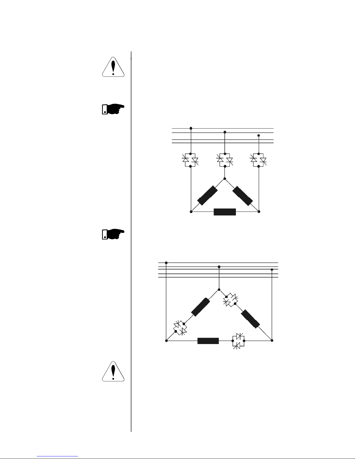
ATTENTION!
Please check which type of connection is used to connect the
SSW-03 Plus to the motor: standard connection or SSW-03
Plus is connected within the motor Delta connection.
Standard connection with three cables: the line current of
the Soft-Starter is equal to the motor current.
SSW-03 Plus is connected within the motor Delta connection with six leads: the line current of the Soft-Starter
is approximately 58% of the motor current.
ATTENTION!
To connect the SSW-03 Plus within the Motor Delta connection, the motor must permit the Delta connection in the desired voltage.
R
S
T
N
PE
R
S
U
S
V
R
W
T
T
R
S
T
N
PE
R S T
U V W
During the start of the motor the current relation of the motor
in relation of the Soft-Starter is 1.50. However in full voltage
condition (after the start time of the motor) the current relation
is 1.73.
1/ U1
4/ U2
2/ V1
5/ V2
6/W 2
3/W 1
1/ U1
4/ U2
2/ V1
5/ V2
6/W 2
3/W 1
Page 4

SUMMARY
SUMMARY
1 Parameters .................................................... 07
2 Error Messages.............................................. 10
3 Soft-Starter Status ........................................ 10
1.1 Safety Notices in the Manual ....................... 11
1.2 Safety Notices on the Product ..................... 11
1.3 Preliminary Recommendations .................... 11
2.1 About this Manual ........................................ 13
2.2 Version of Software ....................................... 13
2.3 Abbreviations Used ....................................... 14
2.4 About the SSW-03 Plus ................................. 14
2.4.1 Introduction ....................................... 14
2.4.2 Simplified Block Diagram of the
SSW-03 Plus ....................................... 16
2.4.3 Description of the control
board - CCS 3.0 X ............................... 17
2.5 Product identification ................................... 18
2.6 Receiving ...................................................... 18
3.1 Mechanical Installation ............................... 19
3.1.1 Environment....................................... 19
3.1.2 Location/Mounting ............................ 20
3.1.3 Kit IP20 .............................................. 22
3.1.4 Connections within the Motor Delta
Connection ......................................... 24
3.2 Electrical Installation ................................... 25
3.2.1 Power/grounding connections........... 25
3.2.2 Location of the power/grounding/
fans connection ................................. 32
3.2.3 Signal and control connections ........ 32
3.2.3.1 Description of the X2 Connector 33
3.2.4 Fan connections ................................. 34
3.2.5 Combination drive "A" Operation
by HMI, Standard Connection ........... 35
3.2.6 Combination Drive "B" operation
through terminals, Standard Connection 37
3.2.7 Combination Drive "C" operation
through terminals, connection within
the motor delta connection ............... 38
3.3 Installation of Optional Devices .................. 40
3.3.1 HMI-3P on the Panel Door................. 40
3.3.1.1 Mechanical Installation ........ 40
3.3.1.2 Electrical Installation............ 41
4.1 Power-up preparation................................... 42
4.2 Power-up ....................................................... 43
QUICK PARAMETER REFERENCES, ERROR MESSAGES
AND STATUS MESSAGES
1
SAFETY NOTICE
2
INTRODUCTION
3
INSTALLATION
4
POWER UP/
COMMISSIONING
Page 5

SUMMARY
SUMMARY
4.3 Commissioning ............................................. 43
4.3.1 Preparation ........................................ 44
4.3.2 Commissioning and Operation via
HMI-3P ............................................... 44
4.3.3 Commissioning and Operation via
Terminals ............................................ 45
4.4 Settings during the Commissioning ............. 46
5.1 Description of the HMI-3P Interface ............ 48
5.2 Use of the HMI-3P ........................................ 49
5.2.1 Use of the HMI-3P for operation ....... 49
5.2.2 Signaling / Indications of the HMI-3P
(display) ............................................. 50
5.3 Parameter changing ..................................... 53
5.3.1 Selection/changing parameters ........ 54
6.1 Standard parameter set at factory .............. 56
6.2 Read Parameters - P71...P77, P82, P96...P99 57
6.2.1 P71 - Software Version ........................ 57
6.2.2 P72 - Motor Current %IN .......................... 57
6.2.3 P73 - Motor Current (A) ...................... 57
6.2.4 P74 - Active Power .............................. 57
6.2.5 P75 - Apparent Power ......................... 57
6.2.6 P76 - Load power factor ..................... 57
6.2.7 P77 - Output voltage ........................... 57
6.2.8 P82 - Motor thermal protection status.. 57
6.2.9 Last errors ............................................ 58
6.3 Regulation Parameters P00...P15,
P22...P42,P45, P47 ....................................... 58
6.3.1 P00 - Parameter Access ....................... 58
6.3.2 P01 - Initial Voltage ............................ 58
6.3.3 P02 - Time of the Acceleration Ramp . 59
6.3.4 P03 - Voltage fall step during
deceleration ....................................... 59
6.3.5 P04 - Time of the deceleration ramp .. 60
6.3.6 P11 - Current limitation ...................... 60
6.3.7 P12 - Immediate overcurrent .............. 62
6.3.8 P14 - Immediate undercurrent............ 63
6.3.9 P13 - Immediate overcurrent time...... 64
6.3.10 P15 - Immediate undercurrent time... 64
6.3.11 P22 - Rated current of the Soft-Starter 64
6.3.12 P23 - Rated voltage of the Soft-Starter 65
6.3.13 P31 - Phase rotation .......................... 65
6.3.14 P33 - Voltage level of the JOG function 66
6.3.15 P34 - DC breaking time....................... 66
6.3.16P35 - DC-Braking voltage level (%UN) 67
6.3.17P36 - Time interval between starts 67
6.3.18 P41 - Voltage pulse time at the start 68
6.3.19 P42 - Voltage pulse level at the start 69
6.3.20 P45 - Pump control ........................... 69
6.3.21 P47 - Auto-reset time ........................ 71
5
USE OF THE HMI
6
DETAILED
PARAMETER
DESCRIPTION
Page 6

SUMMARY
SUMMARY
6.4 Configuration parameters P28, P43, P44,
P46, P50...P57, P61...P64 ............................. 71
6.4.1 P28 - Operation Mode ......................... 71
6.4.2 P43 - By-pass relay ............................. 74
6.4.3 P44 - Energy save ................................ 75
6.4.4 P46 - Default values (it loads factory
parameters) ......................................... 75
6.4.5 P50 - Function of the relay RL3............ 76
6.4.6 P51 - Function of the relay RL1 .......... 76
6.4.7 P52 - Function of the Relay RL2 ......... 77
6.4.8 P53 - Programming of the digital
input 2 ................................................. 78
6.4.9 P54 - Programming of the digital
input 3 ................................................. 79
6.4.10 P55 - Programming of the digital
input 4 ................................................. 79
6.4.11 P56 - Programming of the analog
output .................................................. 80
6.4.12 P57 - Scaling of the analog output .. 80
6.4.13 P61 - Control enabling ...................... 81
6.4.14 P62 - Address of the Soft-Starter at
the communication network ............... 82
6.4.15 P63 - Watch dog time of the serial
communication ................................... 83
6.4.16 P64 - Action after watch dog time is
elapsed ................................................ 83
6.5 Motor Parameters P21, P25, P26, P27 ......... 84
6.5.1 P21 - Motor Current Setting
(% IN of the switch) .............................. 84
6.5.2 P25 - Thermal Class of the Motor
Protection ............................................ 85
6.5.3 P26 - Motor service factor................... 89
6.5.4 P27 - Auto-reset of the Thermal
motor image ........................................ 90
7.1 Errors and possible causes ........................... 91
7.1.1 Programming error (E24) .................... 91
7.1.2 Serial.................................................... 91
7.1.3 Hardware errors (E0X)......................... 91
7.2 Preventive maintenance ............................... 95
7.2.1 Cleaning instructions .......................... 96
7.3 Changing supply fuse ................................... 96
7.4 Spare part list ............................................... 97
8.1 Power Data ................................................... 99
8.2 Power / current table .................................... 99
8.2.1 Table of Power and Currents for
Three Cable Standard Connection
(Ambient Temperature of 40°C (104°F)) 99
8.2.2 Table of Power and Currents for
Three Cable Standard Connection
(Ambient Temperature of 55°C (131°F)) 99
7
MAINTENANCE
8
TECHNICAL
CHARACTERISTICS
Page 7

SUMMARY
SUMMARY
8.2.3 Table of Power and Currents for
6 Cable Connection within motor
Delta Connection (Ambient Temperature
of 40°C (104°F)) ................................. 100
8.2.4 Table of Power and Currents for
6 Cable Connection with in motor
Delta Connection (Ambient Temperature
of 55°C (131°F)) ................................. 100
8.3 Mechanical data ........................................... 101
8.4 Electronics data ............................................ 101
8.5 Electronics data/general .............................. 101
9.1 Comformity ................................................... 103
9.1.1 EMC and LVD directives ..................... 103
9.1.2 Requirements for conforming
installations ....................................... 104
9.2 Recommended application with terminals for
two wire control ........................................... 105
9.3 Recommended application with terminals for
three wire control ......................................... 106
9.4 Recommended application with terminals for
three wire control and power isolation
contactor ...................................................... 107
9.5 Recommended application with terminals for
three wire control and by-pass contactor ... 108
9.6 Recommended application with terminals for
three wire control and DC braking ............... 109
9.7 Recommended application with terminals for
three wire control and motor speed reversal 110
9.8 Recommended applications with PC or PLC
command ...................................................... 111
9.9 Recommended application with control by
three wire digital inputs and power isolation
contactor and connection within the motor
delta connection of the 6 cable Motor ........ 112
9.10 Recommended drive with control by three-wire
digital inputs, with by-pass contactor and
connection within the motor delta connection
of the motor with 6 cables ........................... 114
9.11 Recommended application with terminals for
three wire control for several motors ........... 115
9.12 Symbols ........................................................ 117
10.1 Recommended drive with control by digital
inputs with three wires and bypass
contactor + MAC-0x .............................. 120
10.2 Fieldbus communication .............................. 121
10.3 SuperDrive .................................................... 121
10
OPTINAL DEVICES
9
APPENDIX
Page 8
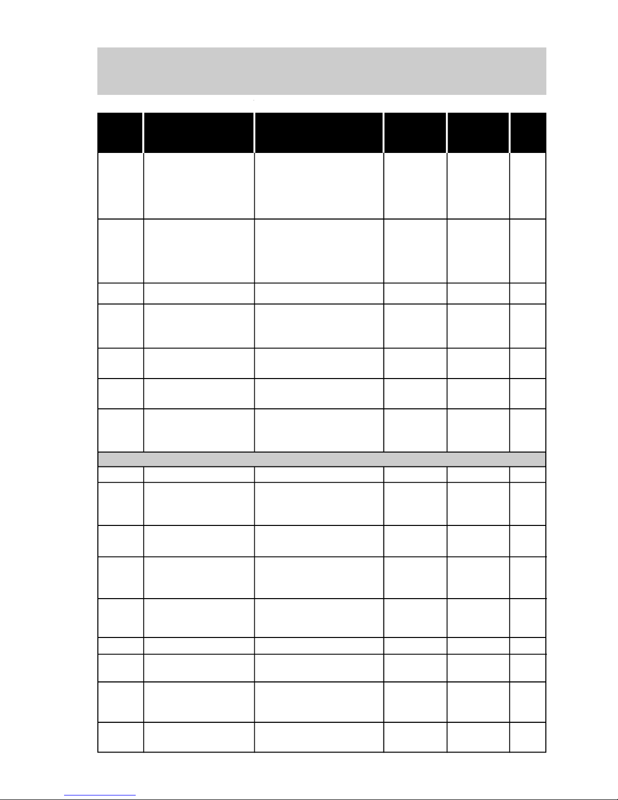
7
QUICK PARAMETER REFERENCES,
ERROR MESSAGES AND STATUS MESSAGES
Software: V5.XX
Application: _______________________________________________________
Type: _____________________________________________________________
Serial Number: ____________________________________________________
Responsable: _____________________________ Date: _____/_____/_____.
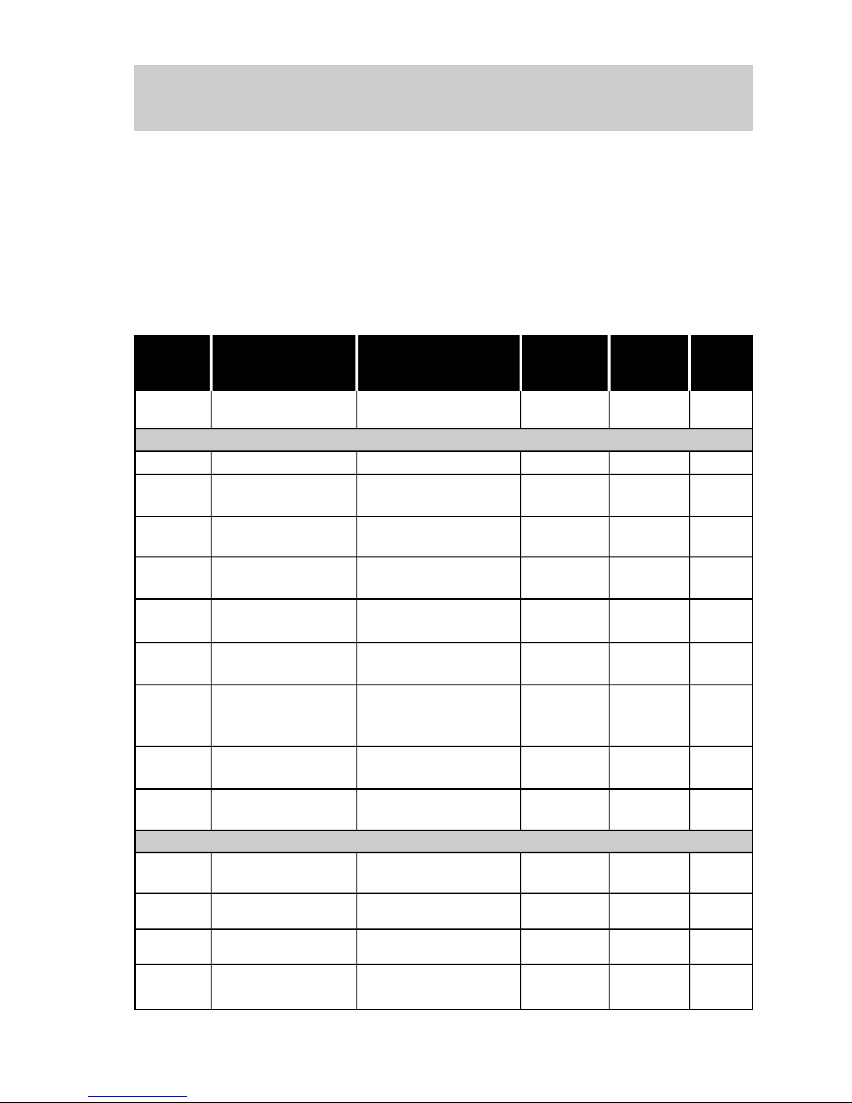
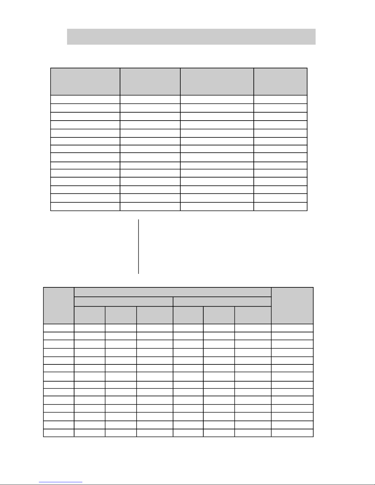
1. Parameters
Para- Function Adjustable Factory User's Page
meter Range Setting Setting
Permits parameter
changing
P00
P01
P02
P03
P04
P11
P12
P13
P14
P15
P21
P25
P26
P27
OFF, ON
25...90% UN
1...240 s
100... 40%UN
OFF,2...240s
OFF,150...500%IN
32...200%IN
OFF, 1...20s
20...190%IN
OFF, 1...200s
OFF, 30.0...200.0%IN
5, 10, 15, 20, 25, 30
0.80...1.50
OFF, 1...600s
OFF
30%UN
20s
100%UN
OFF
OFF
120%IN
OFF
70%IN
OFF
OFF
30
1.00
OFF
58
58
59
59
60
60
62
64
63
64
84
85
89
90
Overload class
Service factor
Auto-reset of the
thermal memory
Regulation Parameter
Motor Parameter
Initial Voltage
Acceleration ramp
time
Voltage fall step
during deceleration
Ramp time during
deceleration
Current limit during
starting
Immediate overcurrent
Immediate overcurrent
time
Immediate undercurrent
Immediate undercurrent time
Motor current setting
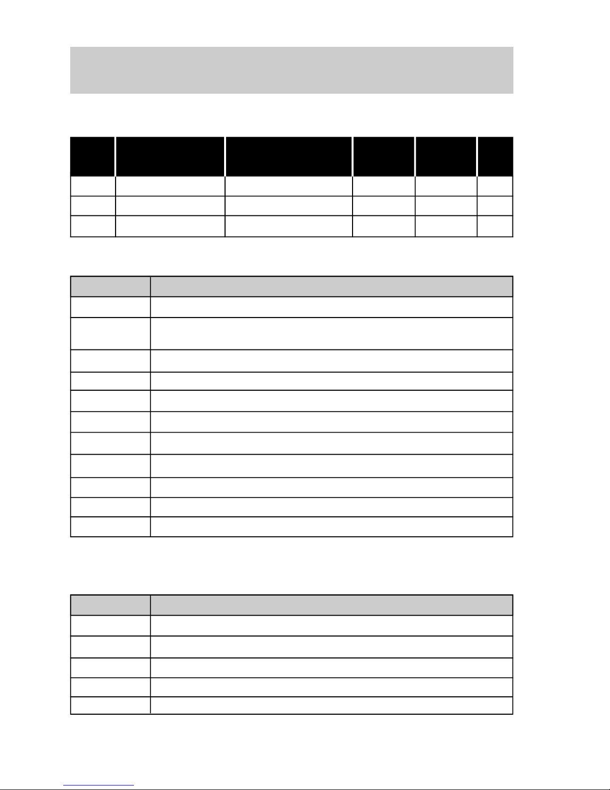
Page 9

8
QUICK PARAMETER REFERENCES,
ERROR MESSAGES AND STATUS MESSAGES
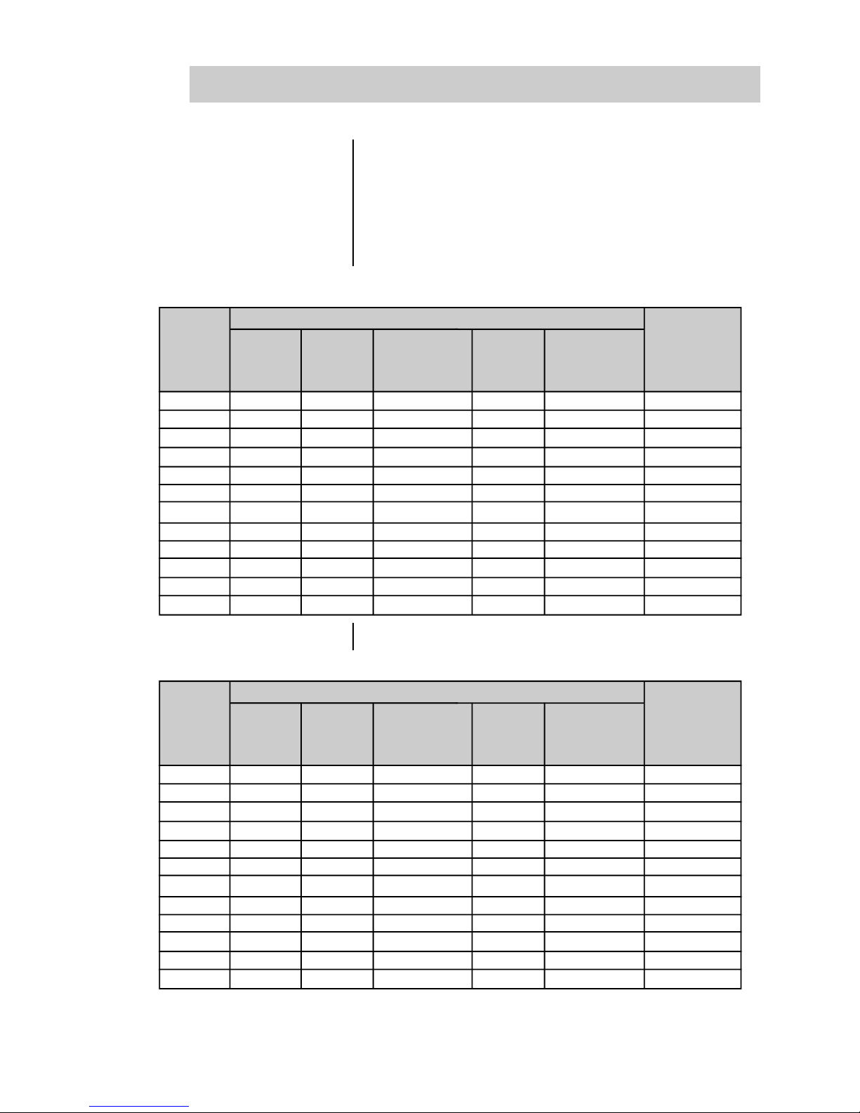
Para- Function Adjustable Factory User's Page
meter Range Setting Setting
P22
P23
P31
P34
P35
P36
P41
P42
P45
P47
P28
P43
P44
P46
P50
P51
P52
P53
P54
Rated current
Rated mains voltage
Phase rotation
Voltage jog level
P33
64
65
65
66
66
67
67
68
69
69
71
71
74
75
75
76
76
77
78
79
DC braking time
DC braking voltage
level
Voltage pulse at start
(kick start)
Pump control
Voltage pulse level
during starting
Errors auto-reset
Configuration Parameter
By-Pass relay
Energy save
Default values
OFF, ON
OFF, ON
Regulation Parameter
Function of the RL1 relay
Digital input 2 program
Digital input 3 program
OFF, ON
According to
the Model
380V
OFF
25%UN
OFF
30%UN
2s
OFF
70%UN
OFF
OFF
OFF
OFF
OFF
2
1
2
120, 170, 205, 255, 290, 340, 410,
475, 580, 670, 800, 950, 1100, 1400A
220, 230, 240, 380, 400, 415, 440,
460, 480, 525, 575V
OFF, ON
25...50%UN
OFF, 1...10s
30...50%UN
OFF, 1...999s
OFF, 0.2...2s
70...90%UN
OFF, ON
OFF, 10...600s
Function of the RL2 relay
Function of the RL3 relay
1- disables with fault
2- enables with fault
1 - Operation
2 - Full Voltage
3 - Direction of Rotation
1
1
Operation mode
OFF, ON
OFF
1 - Operation
2 - Full Voltage
3 - DC Braking
OFF - Without Function
1 - Error Reset
2 - Extern Error
3 - General Enabling
4 - Three Wire Control
OFF - Without Function
1 - Error Reset
2 - Extern Error
3 - General Enabling
4 - Direction of Rotation
Time interval between
starts
Page 10
9
QUICK PARAMETER REFERENCES,
ERROR MESSAGES AND STATUS MESSAGES
Para- Function Adjustable Factory User's Page
meter Range Setting Setting
Indication of the %IN
motor current of the
switch
P72
57
XXX %IN
Motor current indication (A)
P73
P74
P75
P76
P77
P82
P96
Active power indication
supplied to the load
(kW)
Apparent power indication supplied to the
load (kVA)
0...9999A
0...9999kW
0...9999kVA
Load power factor
0.00...0.99
Soft-Starter output
voltage indication % UN
0...100% UN
Indication of motor
Thermal Protection
Status
0...250%
Last hardware error
1...8
57
57
57
57
57
57
58
Digital input 4 program
Analog output program
Analog output gain
0.01...9.99
Set the command
through HMI/Serial or
digital inputs
OFF, ON
OFF
OFF
1.00
ON
Soft-Starter address in
the comunication NET
1...30
1
Reading Parameters
Software version
57
P55
P56
P57
P61
P62
P63
P64
79
80
80
81
82
83
83
OFF - Without Function
1 - Error Reset
2 - Extern Error
3 - General Enabling
4 - JOG Function
OFF - Without Function
1 - Current %IN
2 - Voltage %UN
3 - Power Factor
4 - Thermal Protection
Watch Dog Time of
Serial Communication
OFF, 1...5s OFF
Action after watch Dog
Time is elapsed
1
1 - E29 Indication only
2 - Disable by Ramp E29
3 - General Disabling E29
P71
Page 11
10
QUICK PARAMETER REFERENCES,
ERROR MESSAGES AND STATUS MESSAGES
2. Error Messages
3. Soft-Starter Status
Phase failure or thyristor fault or motor not connected
At the end of time of the programmed acceleration time, the voltage does
not reach 100% UN due to the current limit.
Overtemperature at the thyristors and in the heatsink
Motor overload
Undercurrent (applicable to pumps)
Immediate overcurrent
Phase rotation
External fault
Programming error
Serial communication error
Serial communication error
Display
Meaning
E01
E02
E03
E04
E05
E06
E07
E08
E24
E2X
E29
Soft-Starter is ready to be enabled
Loading pump control parameters
Loading "Default" values
Function enabled
Function disabled
Display
Definition
rdy
PuP
EEP
on
oFF
Second hardware error
1...8
Third hardware error
1...8
Fourth hardware error
1...8
P97
P98
P99
58
58
58
Para- Function Adjustable Factory User's Page
meter Range Setting Setting
Page 12
11
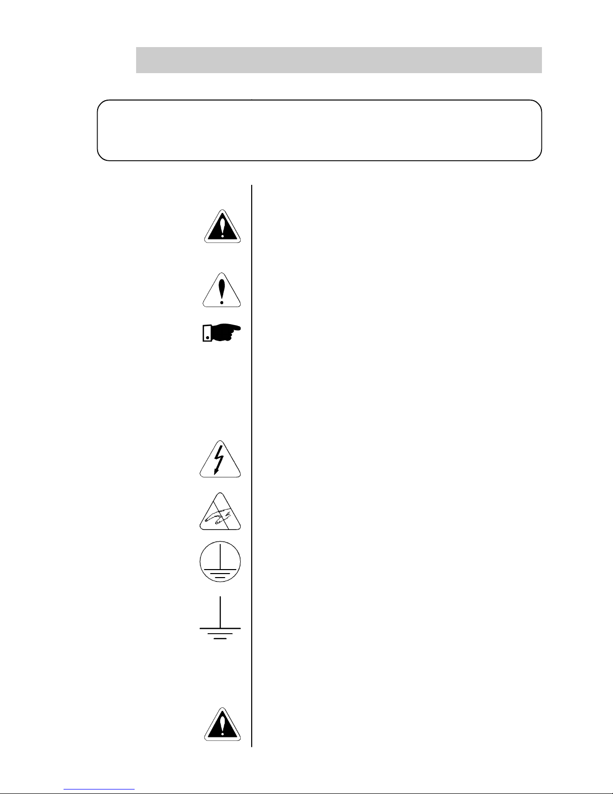
SAFETY NOTICE
1
This Manual contains all necessary information for the correct installation and operation
of the SSW-03 Plus Soft-Starter.
This Manual has been written for qualified personnel with suitable training or technical
qualifications to operate this type of equipment.
The following Safety Notices will be used in this Manual:
DANGER!
If the recommended Safety Instructions are not strictly
observed, it can lead to serious or fatal injuries of personnel
and/or equipment damage.
ATTENTION!
Failure to observe the recommended Safety Procedures can
lead to material damage.
NOTE!
The content of this Manual supplies important information
for the correct understanding of operation and proper
performance of the equipment.
The followingsymbols maybe attachedto the product, serving
as Safety Notice:
High Voltages
Components are sensitive to electrostatic discharge. Do not
touch them without following proper grounding procedures.
Mandatory connection to ground protection (PE)
Shield connection to ground
DANGER!
Onlyqualifiedpersonnelshouldplanorimplement theinstallation,
startup, operation and maintenance of this equipment.
1.3 PRELIMINARY
RECOMMENDATIONS
1.2 SAFETY NOTICES
ON THE PRODUCT
1.1 SAFETY NOTICES
IN THE MANUAL
Page 13
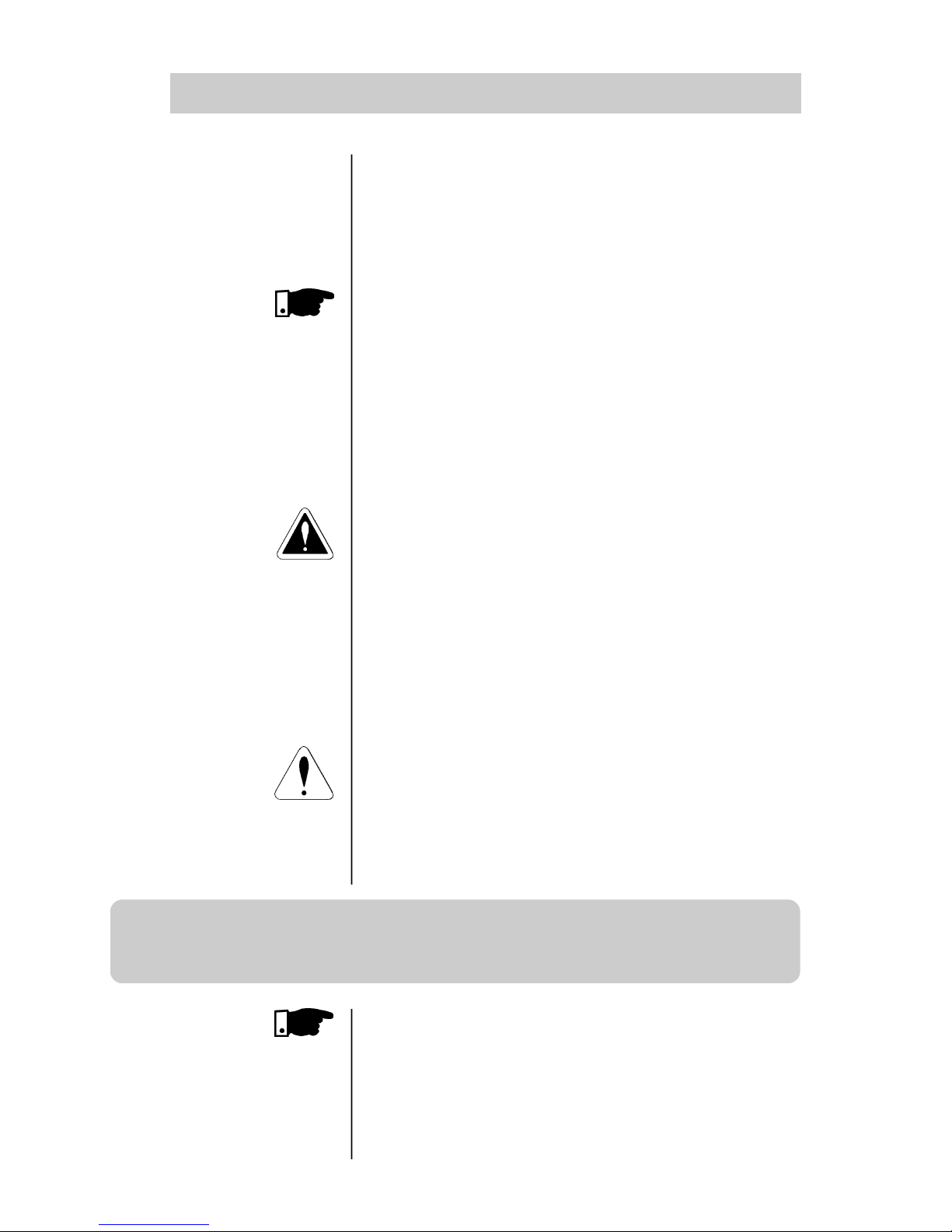
12
1
SAFETY NOTICE
Personnel must review this entire Manual before attempting
to install, operate or troubleshoot the SSW-03 Plus. These
personnel must follow all safety instructions included in this
Manual and/or defined by local regulations.
Failure to comply with these instructions may result in
personnel injury and/or equipment damage.
NOTE!
In this Manual, qualified personnelare defined as people that
are trained to:
1. Install, ground, power up and operate the SSW-03 Plus
according to this manual and the local required safety
procedures;
2. Useofsafety equipment accordingtothelocal regulations;
3. Administer Cardio Pulmonary Resuscitation (CPR) and
First Aid.
DANGER!
Always disconnect the supply voltage before touching any
electrical component inside the Soft-Starter.
Many components are charged with high voltages, even after
the incoming AC power supply has been disconnected or
switched OFF. Wait at least 3 minutes for the total discharge
of the power capacitors.
Always connect the frame of the equipment to the ground
(PE) at the suitable connection point.
ATTENTION!
All electronic boards have components that are sensitive to
electrostatic discharges. Never touch any of the electrical
components or connectors without following proper
grounding procedures. If necessary to do so, touch the
properly grounded metallic frame or use a suitable ground
strap.
NOTE!
Read this entire Manual carefully and completely before
installing or operating the SSW-03 Plus.
Do not apply High Voltage (High Pot) Test on the Soft-Starter!
If this test is necessary, contact the Manufacturer.
Page 14

13
2
INTRODUCTION
2.1 - ABOUT THIS
MANUAL
This Manual describes how to install, start-up, operate and
identify the problems of the SSW-03 Plus Soft-Starters series.
Should you require any training or further info, please contact
WEG.
This Manual is divided into 10 Chapters, providing
information to the user on how to receive, install, start-up
and operate the SSW-03 Plus:
Chapter 1- Safety Notices;
Chapter 2 - Introduction;
Chapter 3 - Installation;
Chapter 4 - Power-up / Commissioning;
Chapter 5 - Use of the HMI;
Chapter 6 - Detailed Parameter Description;
Chapter 7 - Maintenance;
Chapter 8 - Technical Characteristics;
Chapter 9 - Appendix;
Chapter 10- Optional Devices.
This Manual provides information for the correct use of the
SSW-03 Plus. The SSW-03 Plus is very flexible and allows for
the operation in many different modes as described in this
manual.
As the SSW-03 Plus can be applied in several ways, it is
impossible to describe here all of the application possibilities.
WEG does not accept any responsibility when the SSW-03 Plus
is not used according to this Manual.
No part of this Manual may be reproduced in any form,
without the written permission of WEG.
It is important to note the Software Version installed in the
Version SSW-03 Plus, since it defines the functions and the
programming parameters of the Soft-Starter.
This Manual refers to the Software version indicated on the
inside cover. For example, the Version 1.XX applies to versions
1.00 to 1.99, where “X” is a variable that will change due to
minor software revisions. The operation of the SSW-03 Plus
with these software revisions are still covered by this version
of the Manual.
The Software Version can be read in the Parameter P71.
2.2 VERSION OF
SOFTWARE
Page 15

14
2
INTRODUCTION
2.3 - ABBREVIATIONS
USED
HMI - Human machine interface (keypad + display)
HMI-3P - Keypad + Display interface - Linked via parallel
cable
RLX - Relay output No X
DIX - Digital input No X
IN - Soft-Starter nominal output current
UN - Rated mains voltage
LED - Light Emitting Diode
2.4 - ABOUT THE
SSW-03 PLUS
The SSW-03 Plus series is a totally microprocessor controlled
Soft-Starter series which controls the starting current of threephase induction motors. In this way mechanical inmpacts on
the load and current peaks on the supply network are
prevented.
2.4.1 - Introduction
This series includes models from 120 to 1400A, being
supplied from 220V, 230V, 240V, 380V, 400V, 415V, 440V,
460V, 480V, 525V or 575V. (The available types are listed in
Section 8).
The models up to 205A are fitted with forced cooling and
isolated heatsink (thyristor-thyristor modules). The models
from 255A up to 1400A have forced cooling and energized
heatsink. (Disc thyristors).
The electronic control circuit uses a 16 bit microprocessor with
high performance, allowing settings and displaying by means
of the interface (keypad + display) of all needed parameters.
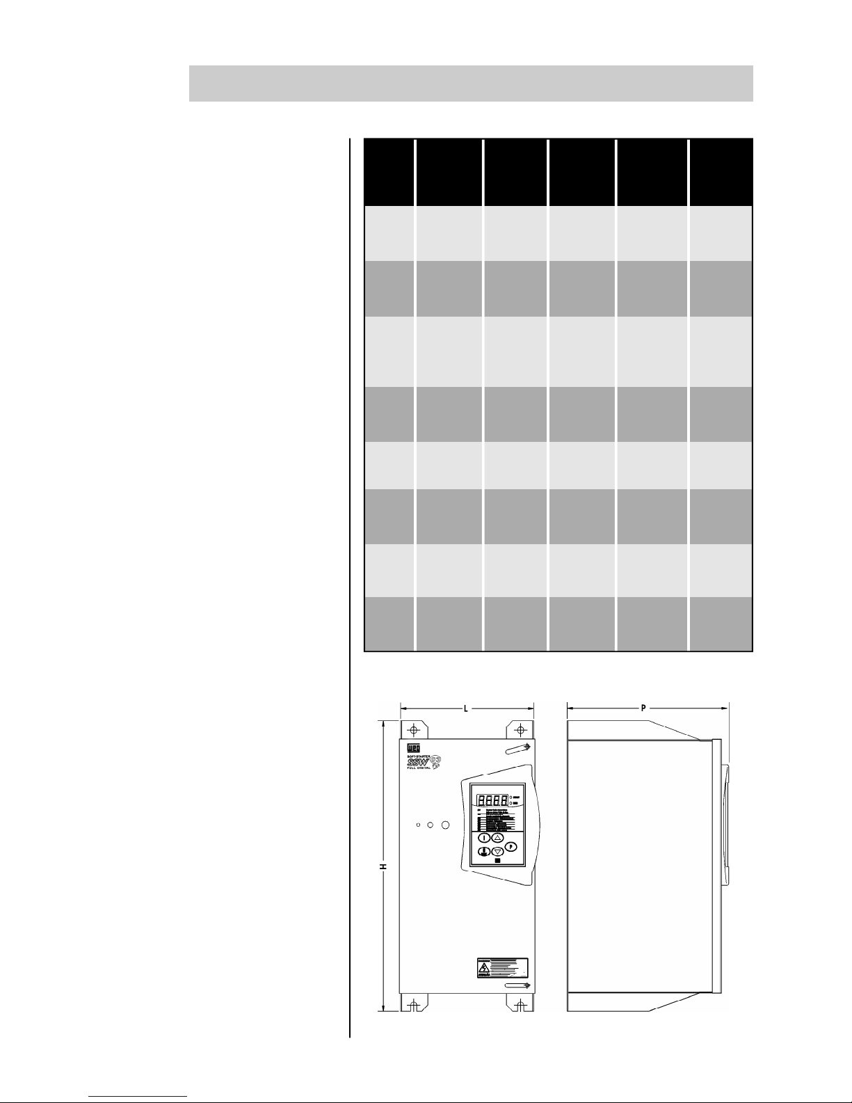
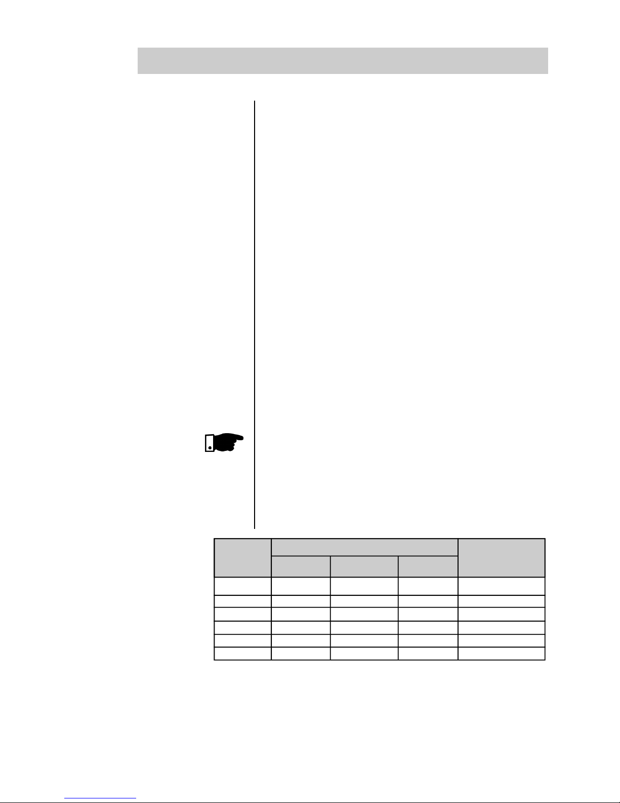
Depending on the power, this series (SSW-03 Plus) has 8
different construction forms, as shown in Figure 2.1.
Page 16
15
2
INTRODUCTION
Width Depth Height Weight
MEC Rated L P H Kg
Current mm (in) mm (in) mm (in) (Lb)
224 244 365 16.8
0 120A (8.82) (9.61) (14.37) (37.04)
170A 224 257 480 20.2
1 205A (8.82) (10.12) (18.9) (44.53)
255A
2 290A 521 315 530 41.8
340A (20.51) (12.4) (20.86) (92.15)
410A 521 325 605 50
3 (20.51) (12.79) (23.81) (110.20)
475A 521 325 655 58.8
4 580A (20.51) (12.79) (25.78) (129.60)
670A 521 325 705 64
5 (20.51) (12.79) (27.75) (141.06)
800A 521 345 855 71.8
6 950A (20.51) (13.82) (33.66) (158.25)
7 1100A 679 431 1210 180
1400A (26.73) (16.97) (47.63) (396.72)
Figure 2.1 - Construction forms
FRONT VIEW
SIDE VIEW
Page 17
16
2
INTRODUCTION
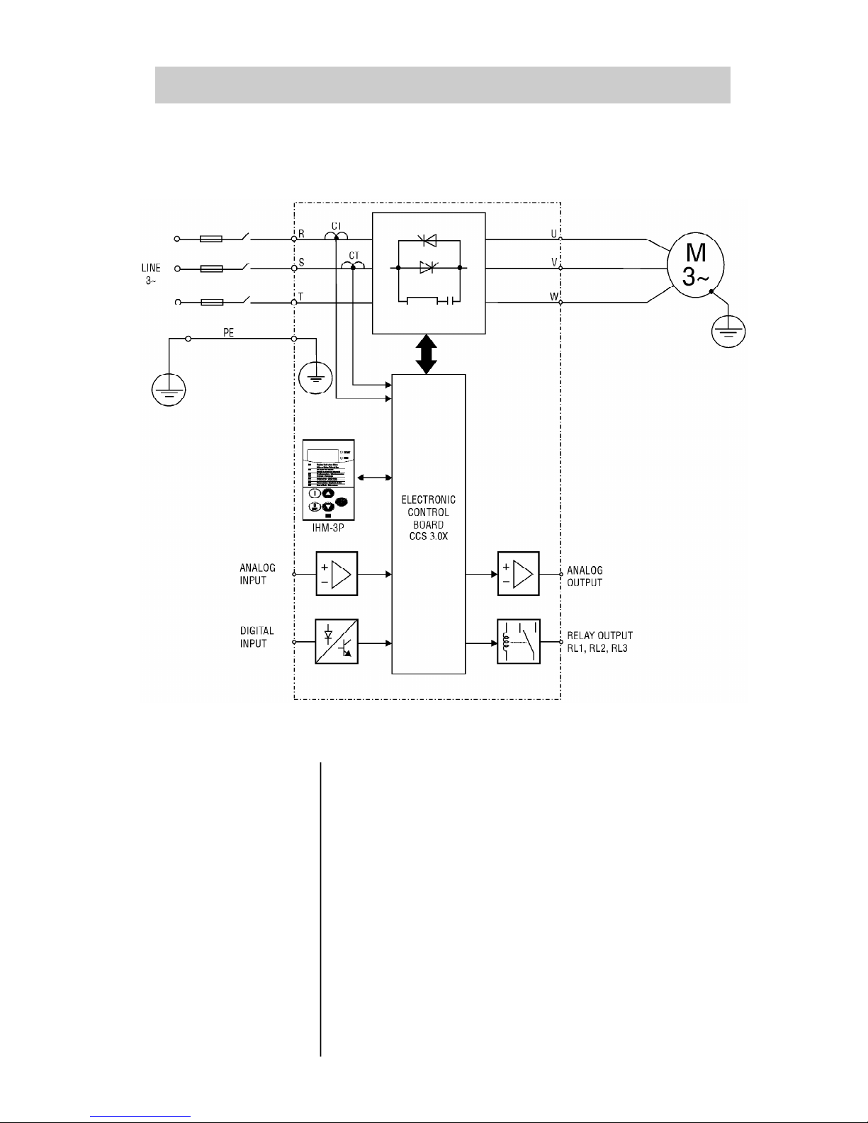
2.4.2 - Simplified Block Diagram of the SSW-03 Plus
In the power stage, the line voltage is controlled by means of
6 SCR’s that allow the variation of the conduction angle of
the voltage supplied to the motor.
For the internal supply of the electronics, a linear source is
used with several voltages, fed independently of the power
supply.
The control board contains the circuits responsible for the
control, monitoring and protection of the power components.
This board also contains the control and signalling circuit to
be used by the user according to its application as a relay
output.
All parameters or controls for the operation of the Soft-Starter
can be displayed or changed through the HMI.
Figure 2.2 - Simplified Block Diagram of the SSW-03 Plus
Page 18
17
2
INTRODUCTION
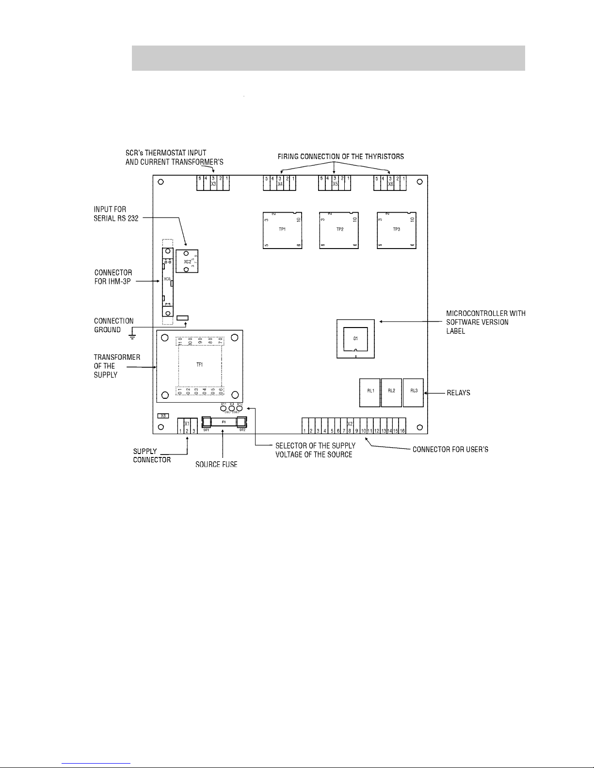
2.4.3 - Description of the control board - CCS 3.0X
Figure 2.3 - Layout of the electronic control board CCS 300 or CCS 3.01
Page 19
18
2
INTRODUCTION
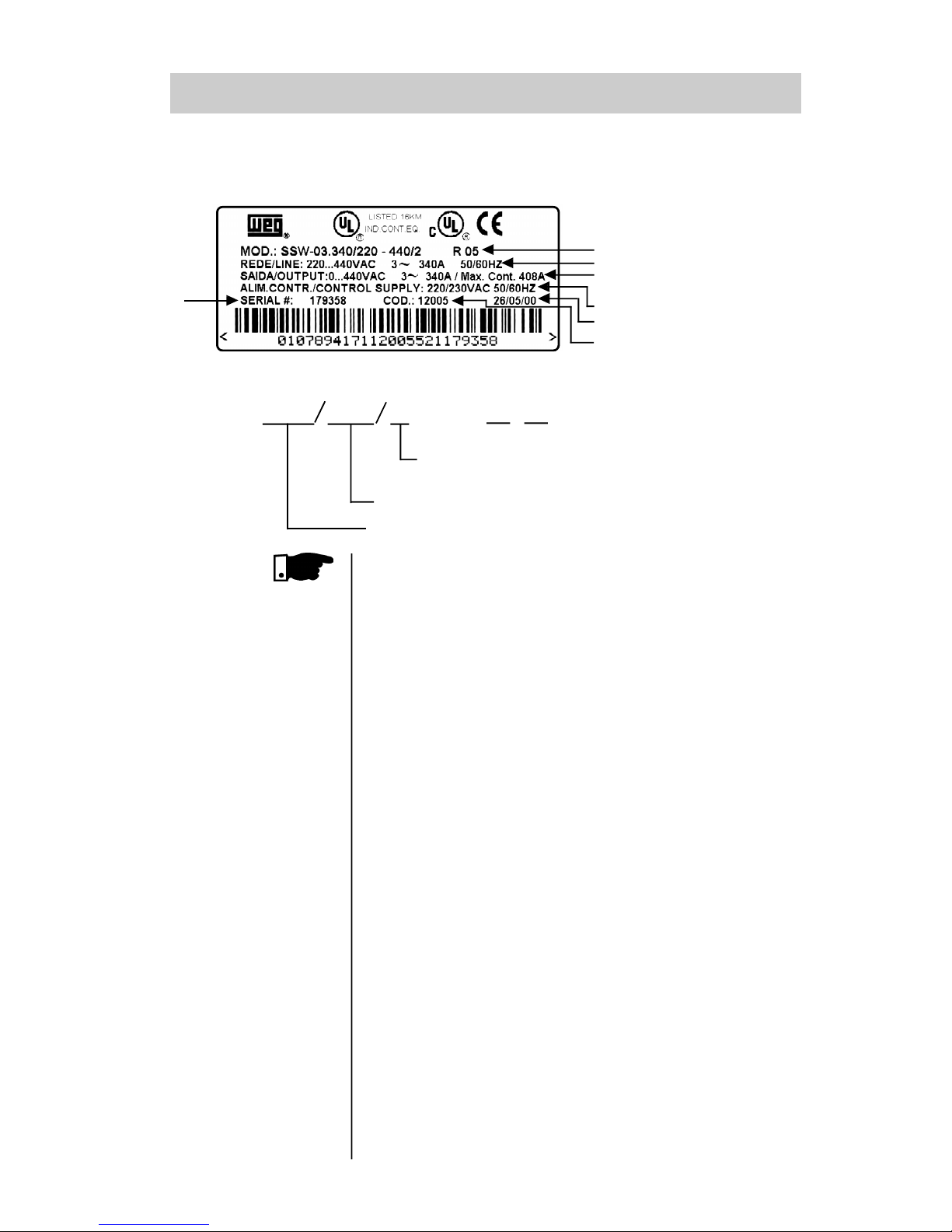
2.5 - PRODUCT
IDENTIFICATION
EXTERN HMI
HMI-3P.1: HMI with LEDs, 1 m (3.28ft) cable
HMI-3P.2: HMI with LEDs, 2 m (6.56ft) cable
HMI-3P.3: HMI with LEDs, 3 m (9.84ft) cable
2.6 - RECEIVING
Max. Cont.: It's the maximum current that the Soft-Starter can
have in continuous duty. For this current the Soft-Starter can
only have 1 start per hour.
The SSW-03 Plus is supplied in cardboard boxes up to 205A,
current sizes from 255 to 1400A are supplied in wood crates.
The outside of the packing container has a nameplate that is
the identical to that on the SSW-03 Plus. Please check if the
SSW-03 Plus is the one you ordered.
Open the box, remove the foam and then remove the SSW-03
Plus.
For sizes above 255 A, open the wooden crate on the floor,
remove the fastening bolts on the base and remove the SSW03 Plus with the aid of a hoist.
Check if:
SSW-03 Plus nameplate data matches the purchase order;
The equipment has not been damaged during transport.
If any problem is detected, contact the carrier immediately.
If the SSW-03 Plus is not to be installed immediately, store it
in a clean and dry room (Storage temperatures between 25°C and 60°C). Cover it to prevent dust, dirt or other
contamination.
Rated output current (A)
Three-phase supply voltage (220 - 440, 460 - 575)
Options : + I with remote HMI
+
Voltage of the electronics
1- 110/120 V
2- 220/230 V
Soft-Starter Type
{
SSW-03
SERIAL NUMBER
WEGITEM
FABRICATION DATE
ELECTRONIC/FAN DATA
OUTPUTDATA/MAXIMUM CURRENT RATINGFOR
CONTINUOUS DUTY
INPUT DATA
SOFT-STARTERMODEL
- PL
- PL
Page 20
19
INSTALLATION
3
3.1 - MECHANICAL
INSTALLATION
3.1.1 - Environment
The location of the installation is a determinaning factor for
obtaining a good performance and a normal useful life of its
components.
Regarding the installation of the Soft-Starter we make the
following recommendations:
All dimensions in mm (inches)
SSW-03 Panel Dimensions
Blower
Type
Width Height Depth
CFM
(m3/min)
120A 600 (23.62) 1500 (59.05) 400 (15.75) 226 (6.4)
170/205A 600 (23.62) 1500 (59.05) 400 (15.75) 885 (25.08)
255 to 580A 800 (31.50) 2000 (78.74) 600 (23.62) 885 (25.08)
670/950A 800 (31.50) 2000 (78.74) 600 (23.62) 1,757.30 (49.80)
1100A 800 (31.50) 2000 (78.74) 600 (23.62) 1,757.30 (49.80)
1400A 800 (31.50) 2000 (78.74) 600 (23.62) 2,648.44 (75.0)
Avoid directexposure to sunlight, rain, highmoistureandsea air.
Avoid exposure to gases or explosive or corrosive liquids;
Avoid exposure to excessive vibration, dust, oil or any
(conductive particles or materials).
Environmental Conditions:
Temperature: 32...104º F (0 ... 40ºC) - nominal conditions.
104...131º F (40 ... 55º C) - current see table 8.2.
Relative Air Humidity: 5% to 90%, non-condensing.
Maximum Altitude: 3,300 ft (1000m) - nominal conditions.
3,300 ... 13,200 ft (1000 ... 4000m) - with 10% current
reduction for each 3,300 ft(1000m) above 3,300 ft (1000m).
Pollution Degree: 2 (according to EN50178 and UL508)
(It is not allowed to have water,
condensation or conductive dust/
particles in the air)
NOTE!
When Soft-Starter is installed in panels or closed metallic boxes, adequate cooling is required to ensure that the
temperature around the Soft-Starter will not exceed the
maximum allowed temperature. See Dissipated Power in
Section 8.2.
Please meet the minimum recommended panel dimensions
and its cooling requirements:
Page 21
20
INSTALLATION
3
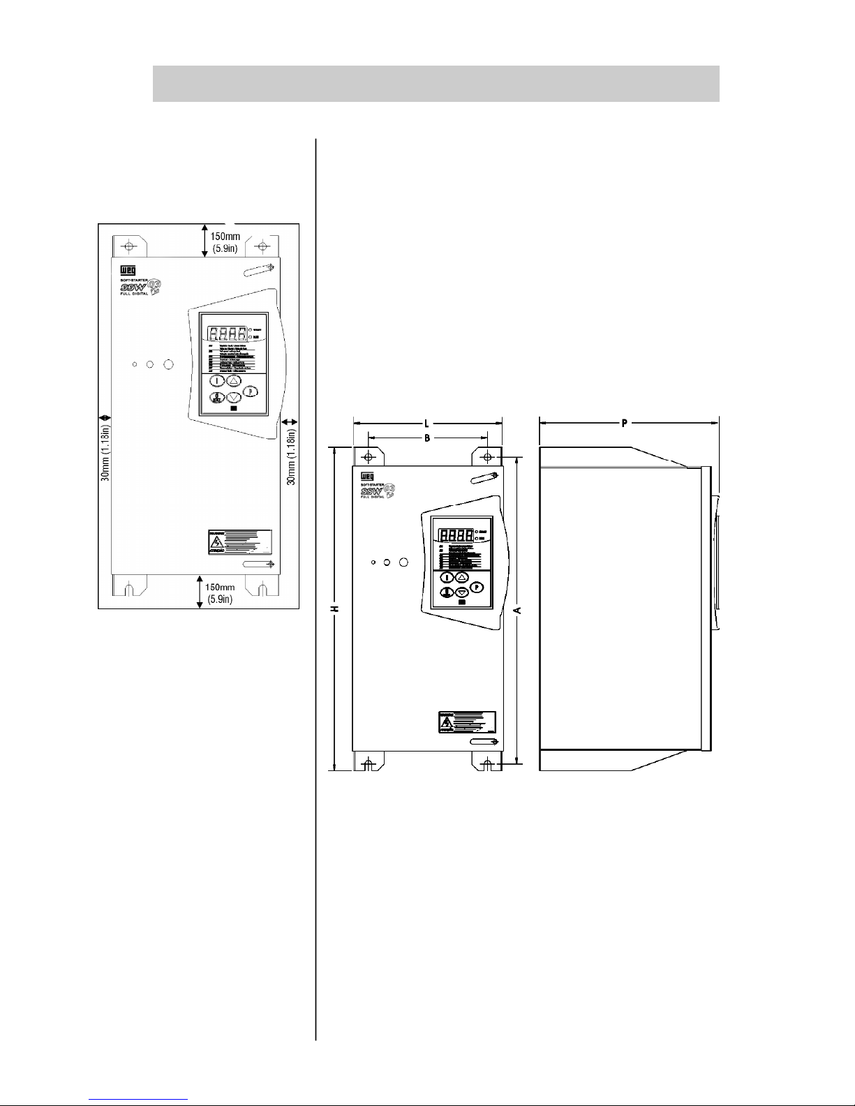
Install the Soft-Starter in Vertical Position:
Allow for free space around the SSW-03 Plus, as shown in
Figure 3.1.
Install the Soft-Starter on a flat surface.
External dimensions, fastenings drillings, etc. according to
Figure 3.2.
First install and partially tighten the mounting bolts, then
install the Soft-Starter and tighten the mounting bolts.
Provide independent conduits for physical separation for
signal conductors, control and power conductors (See
Electrical Installation).
3.1.2 - Location /
Mounting
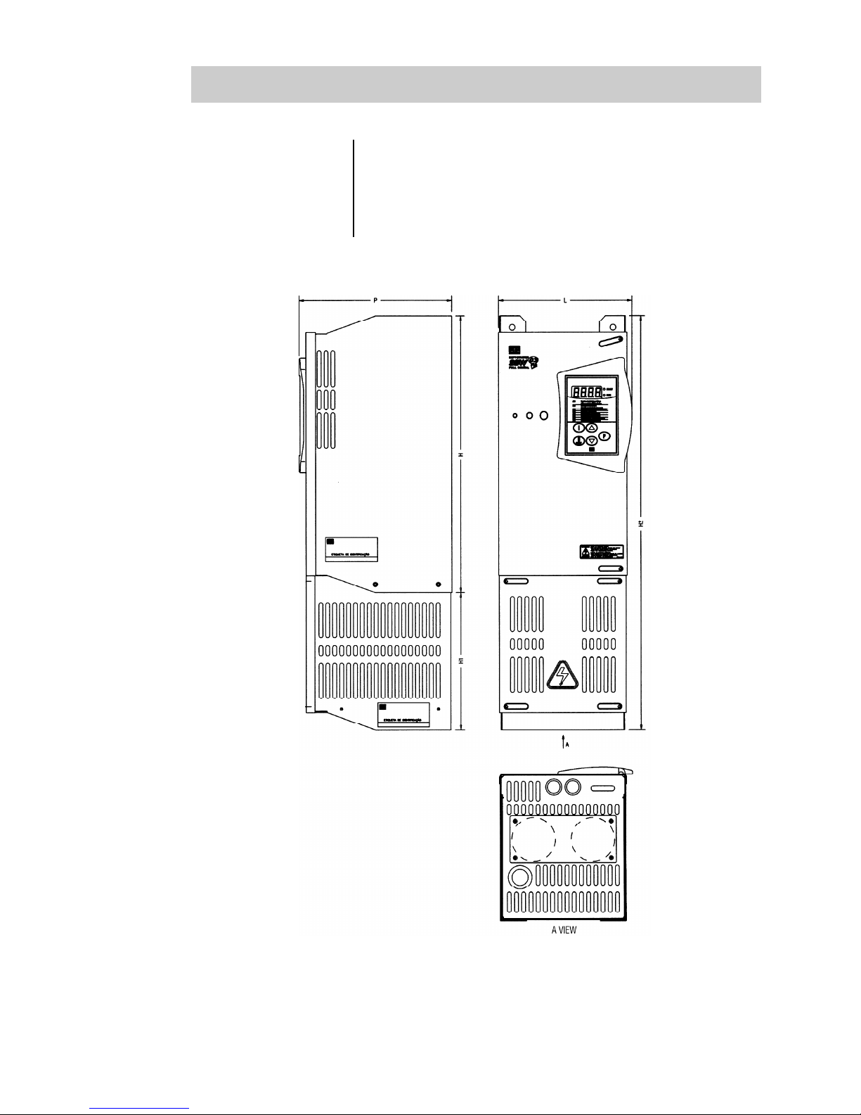
Figure 3.2 -
External dimensions for the SSW-03 Plus and
its screwing drillings
Figure 3.1 - Free space for
ventilation
Page 22
21
INSTALLATION
3
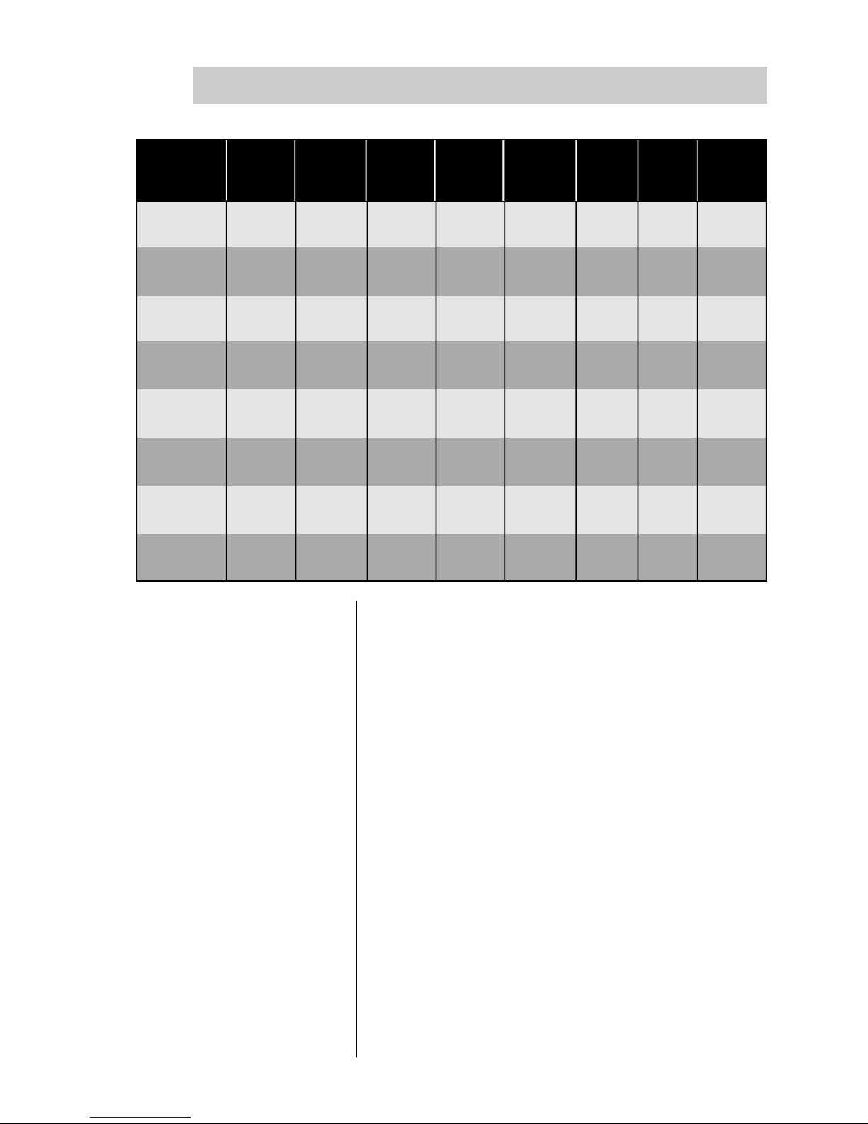
Type Width Height Depth Fasten. Fasten. Fasten Weight Degree
L H P A B bolt kg Protect.
mm (in) mm (in) mm (in) mm (in) mm (in) (lb)
120A
224 365 244 350 175 (5/16") (37.04) Chassis
(8.82) (14.37) (9.61) (13.78) (6.89) M8 16.8 IP00
170/205A
224 480 257 450 175 (5/16") (44.53) Chassis
(8.82) (18.9) (10.12) (17.72) (6.89) M8 20.2 IP00
255...340A
521 530 315 500 350 (5/16") (92.15) Chassis
(20.51) (20.86) (12.4) (19.68) (13.78) M8 41.8 IP00
410A
521 605 325 575 350 (5/16") (110.20) Chassis
(20.51) (23.81) (12.79) (22.63) (13.78) M8 50.0 IP00
475/580A
521 655 325 625 350 (5/16") (129.60) Chassis
(20.51) (25.78) (12.79) (24.60) (13.78) M8 58.8 IP00
670A
521 705 325 675 350 (5/16") (141.06) Chassis
(20.51) (27.75) (12.79) (26.57) (13.78) M8 64 IP00
800/950A
521 855 345 775 350 (5/16") (158.25) Chassis
(20.51) (33.66) (13.58) (30.51) (13.78) M8 71.8 IP00
1100/1400A
679 1210 431 1110 250/250 (3/8") (396.72) Chassis
(26.73) (47.63) (16.97) (43.70) (9.84/9.84) M10 180 IP00
Page 23
22
INSTALLATION
3
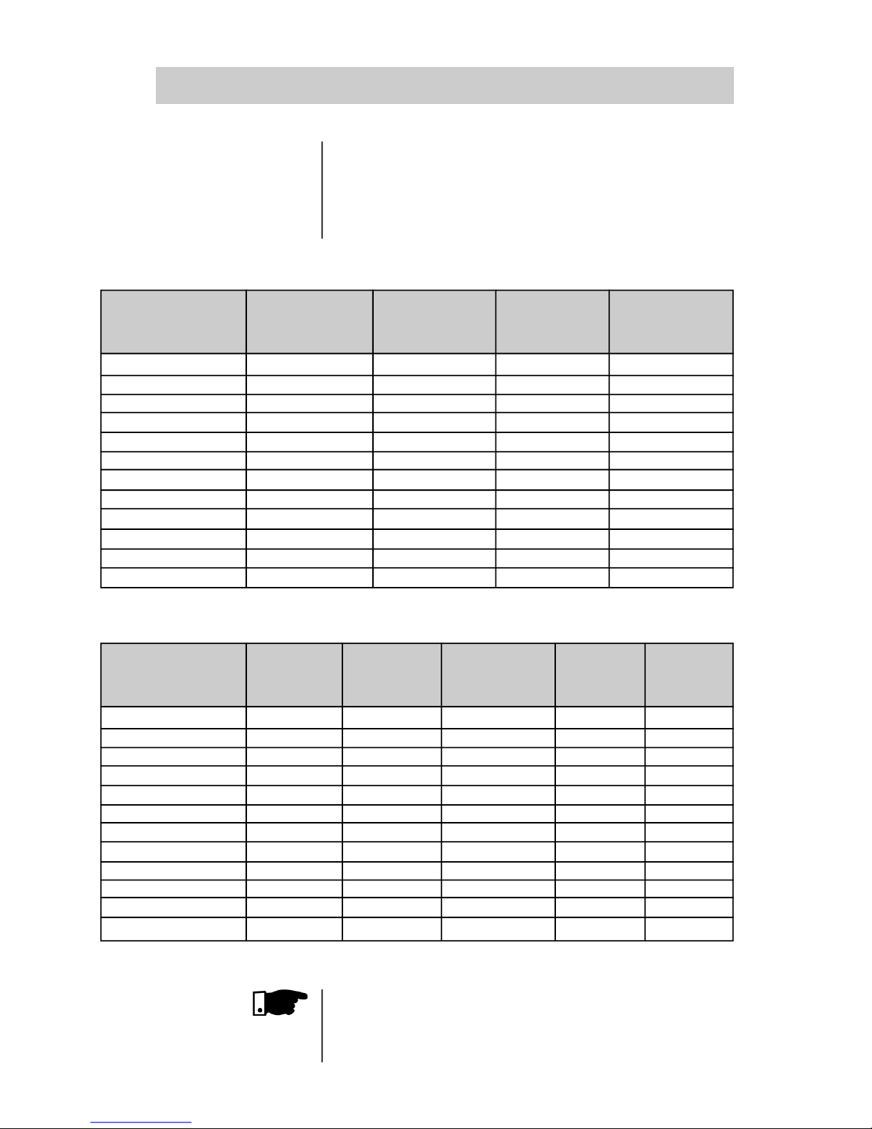
3.1.3 - Kit IP20
The use of the IP20 Kit permits the installation of the input
and output cables, ensuring a degree of protection IP20, and
consequently not permitting direct access to conductive parts,
since it does not have openings larger than 12 mm (0.47 in).
Table for conduits of the Kit IP20
Type
SSW-03 Plus ( A )
120
170
205
255
290
340
410
475
580
670
800
950
Control
Conduit
( In )
½
½
½
½
½
½
½
½
½
½
½
½
Power
Conduit
( In )
1 ½
2 ½
2 ½
3
3
3
3
4
4
5
6
6
Grounding
Conduit
( In )
1
1
1
1 ½
1 ½
1 ½
1 ½
1 ½
1 ½
2
2 ½
2 ½
Kit IP20
Weg Item-N
o
417112100
417112101
417112101
417112102
417112102
417112102
417112103
417112104
417112104
417112105
417112106
417112106
NOTE!
The connection can not be performed within the delta
connection of the motor when Kit IP20 is used.
Table with Kit IP20 Dimensions - See Figure 3.3
Type
SSW-03 Plus ( A )
120
170
205
255
290
340
410
475
580
670
800
950
Width
L
mm (in)
224 (8.82)
224 (8.82)
224 (8.82)
521 (20.51)
521 (20.51)
521 (20.51)
521 (20.51)
521 (20.51)
521 (20.51)
521 (20.51)
521 (20.51)
521 (20.51)
Height
H
mm (in)
365 (14.37)
480 (18.90)
480 (18.90)
530 (20.86)
530 (20.86)
530 (20.86)
605 (23.81)
655 (25.78)
655 (20.86)
705 (27.75)
855 (33.66)
855 (33.66)
Depth
P
mm (in)
244 (9.61)
257 (10.12)
257 (10.12)
315 (12.40)
315 (12.40)
315 (12.40)
325 (12.79)
325 (12.79)
325 (12.79)
325 (12.79)
345 (13.58)
345 (13.58)
Height
H1
mm (in)
240 (9.45)
240 (9.45)
240 (9.45)
356 (14.01)
356 (14.01)
356 (14.01)
356 (14.01)
356 (14.01)
356 (14.01)
406 (15.98)
483 (19.01)
483 (19.01)
Height
H2
mm (in)
605 (23.82)
720 (28.34)
720 (28.34)
886 (34.88)
886 (34.88)
886 (34.88)
961 (37.83)
1011 (39.80)
1011 (39.80)
1111 (43.74)
1288 (50.70)
1288 (50.70)
Page 24
23
INSTALLATION
3
TheKitIP20mustbeinstalledatthebottomoftheSSW-03
Plusafterithas been.
ThisKitIP20 isfixedtothe Soft-Starter bymeansofscrews
supplied with the Kit.
Figure 3.3 - SSW-03 Plus with Kit IP20
Page 25
24
3
3.1.4 - Connections
Within the Motor
Delta Connection
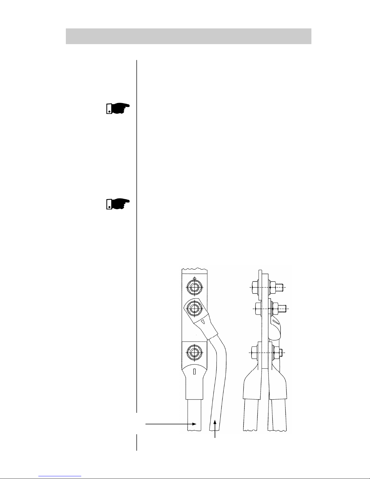
When connection is made within the motor connect as delta
connection, follows :
Motor Cable
Line Cable
INSTALLATION
NOTE!
SSW-03 Plus is suppliedwith an extension bus bar toenable the
connection of more cables to the SSW-03 Plus input bus bar.
Do not use this extension busbar when SSW-03 Plus connection
to line supply is made by means of bus bar.
Thedrawing below is orientative. Dependingon the Soft-Starter
type, the extension bus bar may have one, two or three holes.
NOTE!
1)The connection cables of the Soft-Starter to the line supply,
or the line supply isolation contactor must be able to carry
the motor rated current, and the motor connection cables to
the Soft-Starter, and/or the bypass contactor must be able to
carry 58% of the motor rated current.
2) Due to the high currents and cable cross sections, it is also
suggested to use copper bus bar for this type of connection.
3)When 2 poles motors are in full voltage it is necessary a
minimum of 25% ofload applied to its axle. When thiscondition
can not be taken, a bypass contactor is necessary.
Page 26
25
INSTALLATION
3
3.2 - ELECTRICAL
INSTALLATION
3.2.1 - POWER/
GROUNDING
CONNECTIONS
ATTENTION!
The connection of the motor to the Soft-Starter must be realized
carefully. Follow strictly the connection diagrams according to
the winding types shown in figure 3.5 and item 6.4.1.
If reversal of motor direction of rotation is required, change
the Soft-Starter connection to the line supply. Ensure that
power is switched OFF while connections are changed.
Do not start motor with wrong P28 content:
OFF = standard connection
ON = within the motor delta connection
DANGER!
AC input disconnect: provide an AC input disconnecting switch
to switch OFF input power to the Soft-Starter.
This device shall disconnect the Soft-Starter from the AC input
supply when required (e.g. during maintenance services).
DANGER!
The AC input disconnect cannot be used as an emergency
stop device.
DANGER!
Be sure that the AC input power is disconnected before
making any terminal connection.
DANGER!
The information below will be a guide to achieve a proper
installation. Follow also all applicable local standards for
electrical installations.
ATTENTION!
Provide at least 10 in (0.25m) spacing between low voltage
wiring and the Soft-Starter. , line or load reactors, AC input
power, and AC motor cables.
ATTENTION!
Control of overvoltage in the line that supply the Soft-Starter
must be made using protective of surge with voltage of
550Vac (for models 220 - 440Vac) and 680Vac (for models
460 - 575Vac) connection phase to phase, and absortion
energy capacity of 80 joules.
Page 27
26
INSTALLATION
3
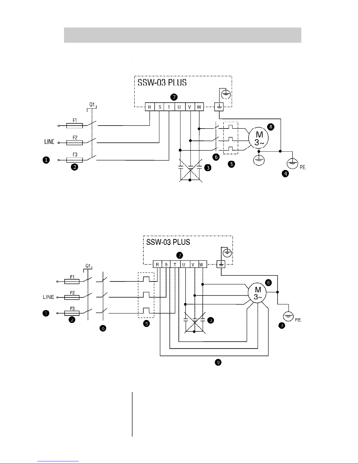
Figure 3.4 -
Power and Grounding Connections for standard connection
Figure 3.5 -
Power and Grounding Connections for connection within the motor delta
connection. See also item 6.4.1 in the manual
Page 28
27
The line voltage must be compatible with the rated voltage
of the Soft-Starter.
For installation use the cable cross sections and the fuses
recommended in Table 3.1, 3.2, 3.3, 3.4. Maximum torque as
indicated in table 3.5.
Power factor correction capacitors must never be installed
on the Soft-Starter output.
The Soft-Starters must be grounded. For this purpose use a
cable with a cross section as indicated in Tables 3.2, 3.3, 3.4.
Connect it to a specific grounding bar or to the general
grounding point (resistance 10 ohms).
Do not share the grounding wiring with other equipment
which operate at high currents (for instance, high voltage
motors, welding machines, etc.).
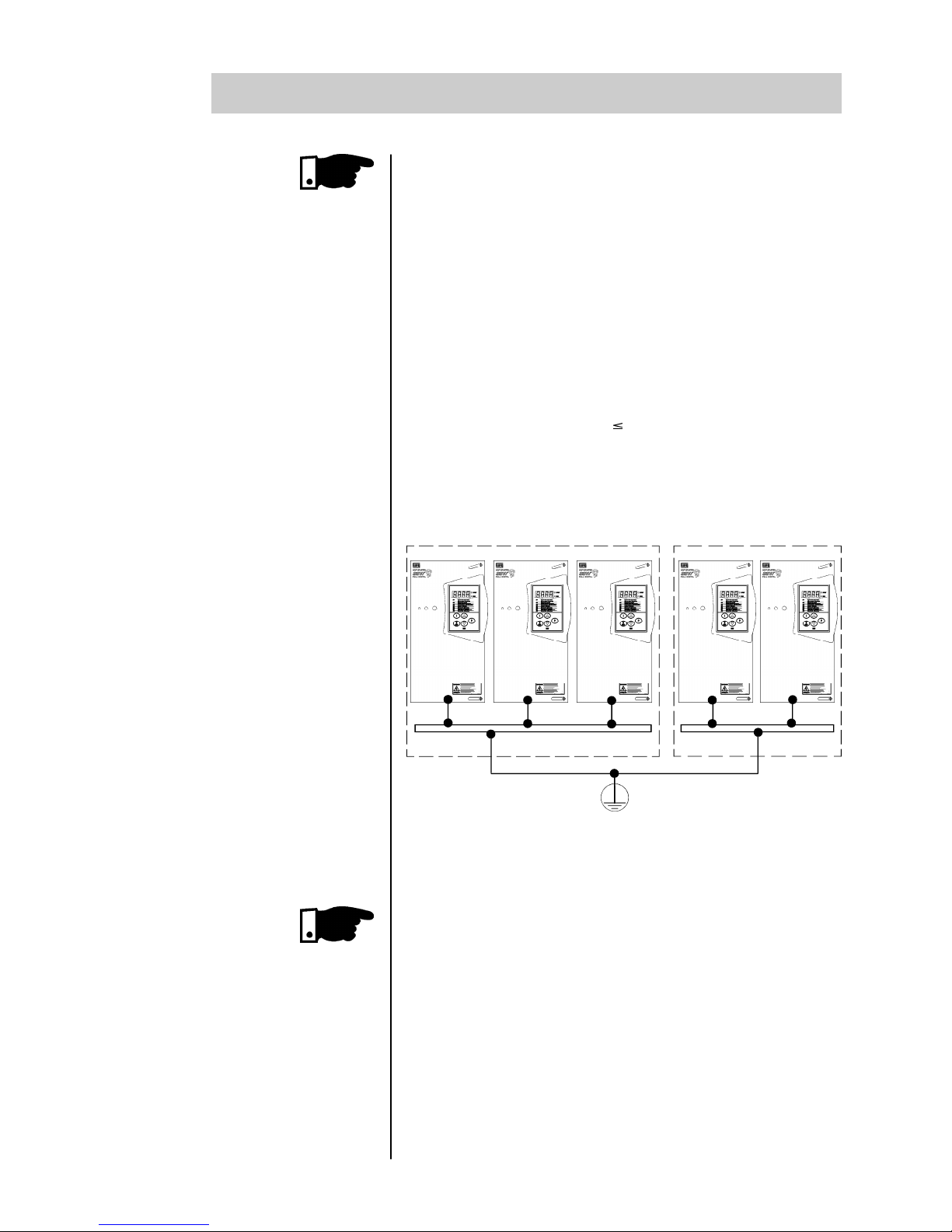
If several Soft-Starters are used together, see Figure 3.6.
Figure 3.6 - Grounding connection for more than one
Soft-Starter
Grounding bar Internal to the panel
The Soft-Starter is fitted with electronic protection against
motor overloads. This protection must be set according to the
specific motor.
When several motors are connected to the same Soft-Starter,
use individual overload relays for each motor.
If a isolating switch or a contactor is inserted in the motor
supply, do not operate them with running motor or when the
Soft-Starter is enabled.
SSW-03PlusI SSW-03 PlusIISSW-03PlusI SSW-03 PlusII SSW-03 Plusn
Do not use the neutral conductor for grounding purpose.
INSTALLATION
3
Page 29
28
INSTALLATION
3
Table 3.1- Recommended fuses
Type
SSW-03 Plus (A)
120
170
205
255
290
340
410
475
580
670
800
950
1100
1400
Standard Connection
IN (A)
250
315
450
500
500
700
700
900
900
900
1400
1600
1600
2000
Within the Motor Delta
Connection
IN (A)
450
500
700
700
700
700
1250
1400
1600
1600
2000
2200
-
-
I²t of the SCR
(A²s)
119.3k
256k
330k
370k
370k
370k
1452k
4250k
4250k
4250k
4250k
14000k
14000k
15125k
The input fuses must be of ultrarapid type (U.R.). I²t must be
smaller or equal to 75% of the SCR value indicated above
(A²s). These fuses protect the SCR against short-circuit. Instead of U.R. fuses you can also use normal fuses that protect
the installation against short-circuit, but this type of fuse does
not protect the SCR.
Table 3.2 – Recommended cables for Standard Connection (100% and 120%IN)
Type
SSW-03
Plus (A)
120
170
205
255
290
340
410
475
580
670
800
950
1100
1400
Standard Connection
Rated Current 100%
Current
100% (A)
120
170
205
255
290
340
410
475
580
670
800
950
1100
1400
Cables
(mm2)
35
70
95
120
150
185
240
300
2 x 150
2 x 185
2 x 240
2 x 300
4 x 150
4 x 185
Bus
mm x mm
12 x 2
20 x 3
20 x 3
25 x 5
25 x 5
25 x 5
30 x 5
40 x 5
40 x 5
40 x 10
40 x 10
50 x 10
60 x 10
80 x 10
Maximum Current 120%
Current
120% (A)
144
204
246
306
348
408
492
570
696
804
960
1140
1320
1680
Bus
(mm2)
50
95
120
150
185
240
2 x120
2 x 150
2 x 185
2 x 240
2 x 300
4 x 150
4 x 185
4 x 240
Bus
mm x mm
20 x 3
20 x 3
20 x 3
25 x 5
25 x 5
30 x 5
40 x 5
40 x 5
40 x 10
40 x 10
50 x 10
60 x 10
80 x 10
100 x 10
Grounding
Cables
(mm²)
25
35
50
70
95
95
120
150
150
185
240
300
2 x 150
2 x 185
Page 30
29
3
Table 3.3 – Recommended cables for connection within the motor delta connection (100%IN)
Table 3.4 – Recommended cables for connection within the motor delta connection (120%IN)
Type
SSW-03
Plus (A)
120
170
205
255
290
340
410
475
580
670
800
950
Connection within motor delta connection
Rated
Current
100% (A)
208
294
355
441
502
588
709
822
1003
1159
1384
1644
Line
Cables
(mm2)
95
150
185
300
2 x 120
2 x 150
2 x 185
2 x 240
4 x 120
4 x 150
4 x 185
4 x 240
Line
bus
mm x mm
20 x 3
25 x 5
25 x 5
30 x 5
40 x 5
40 x 10
40 x 10
40 x 10
50 x 10
60 x 10
80 x 10
100 x 10
Motor
Cables
(mm2)
35
70
95
120
150
185
240
300
2 x 150
2 x 185
2 x 240
2 x 300
Grounding
Cables
(mm²)
25
35
50
70
95
95
120
150
150
185
240
300
Motor
bus
mm x mm
12 x 2
20 x 3
20 x 3
25 x 5
25 x 5
25 x 5
30 x 5
40 x 5
40 x 5
40 x 10
40 x 10
50 x 10
Type
SSW-03
Plus (A)
120
170
205
255
290
340
410
475
580
670
800
950
Connection within the motor delta Connection
Rated
Current
120% (A)
249
353
426
529
602
706
851
986
1204
1391
1661
1972
Line
cables
(mm2)
120
185
300
2 x 120
2 x 150
2 x 185
2 x 300
4 x 120
4 x 150
4 x 185
4 x 240
-
Line
bus
mm x mm
20 x 3
25 x 5
30 x 5
40 x 5
40 x 10
40 x 10
40 x 10
50 x 10
80 x 10
80 x 10
100 x 10
120 x 10
Motor
Cables
(mm2)
50
95
120
150
185
240
2 x120
2 x 150
2 x 185
2 x 240
2 x 300
4 x 150
Grounding
Cables
(mm²)
25
35
50
70
95
95
120
150
150
185
240
300
Motor
bus
mm x mm
20 x 3
20 x 3
20 x 3
25 x 5
25 x 5
30 x 5
40 x 5
40 x 5
40 x 10
40 x 10
50 x 10
60 x 10
INSTALLATION
Copper cables with PVC 70°C (158°F) isolation, with ambient
temperature of 40°C (104°F) installed in perforated conduits
and not bunched. Non insulated or silver platedbus bars with
rounded edges with 1 mm radius with ambient temperature
of 40°C (104°F) and bus temperature of 80°C (175°F). For correct cable dimensioning, consider the installation conditions
and the max. permitted voltage drop.
Page 31

30
INSTALLATION
3
Recommended torque on the power terminals
Table 3.5 - Maximum tightening torque for bolts of power part
Type
SSW-03
Plus (A)
120
170/205
255...
340
410
475/580
670
800/950
1100/
1400
StandardConnection
Without Delta Kit
Bolt
R, S, T, U,
V, W
M6
(1/4")
M8
(5/16")
M10
(3/8")
M12
(1/2")
M12
(1/2")
M12
(1/2")
2 x M10
(3/8")
4 x M10
(3/8")
Torque
Nm
(Lb.in)
8.3
(74.38)
19
(166.25)
37
(328.12)
61
(542.50)
61
(542.50)
61
(542.50)
37
(328.12)
37
(328.12)
Bolt
R, S, T
M8
(5/16")
M10
(3/8")
M12
(1/2")
M12
(1/2")
2 x M12
(1/2")
4 x M12
(1/2")
4 x M12
(1/2")
-
With Delta Kit
Torque
Nm
(Lb.in)
19
(166.25)
37
(328.12)
61
(542.50)
61
(542.50)
61
(542.50)
61
(542.50)
61
(542.50)
-
Bolt
U, V, W
M6
(1/4")
M8
(5/16")
M10
(3/8")
M12
(1/2")
M12
(1/2")
M12
(1/2")
2 x M10
(3/8")
-
Torque
Nm
(Lb.in)
8.3
(74.38)
19
(166.25)
37
(328.12)
61
(542.50)
61
(542.50)
61
(542.50)
37
(328.12)
-
Bolt
M6
(1/4")
M8
(5/16")
M10
(3/8")
M12
(1/2")
M12
(1/2")
M12
(1/2")
2 x M10
(3/8")
-
Torque
Nm
(Lb.in)
8.3
(74.38)
19
(166.25)
37
(328.12)
61
(542.50)
61
(542.50)
61
(542.50)
37
(328.12)
-
Within the motor delta connection
Grounding
The Delta Kit is supplied with the SSW-03 Plus.
Copper cables with PVC 70°C (158°F) isolation, with ambient
temperature of 40°C (104°F) installed in perforated conduits
and not bunched.
Non insulated or silver plated bus bars with rounded edges
with 1 mm radius with ambient temperature of 40°C (104°F)
and bus temperature of 80°C (175°F).
For bypass connection use the same cables or bus bars that
are used for motor connection.
For correct cable dimensioning, consider the installation
conditions and the max. permitted voltage drop.
Page 32

31
We do not recommend the use of motors that are operated
in continuous duty with less than 50% of their rated
current.
The rated motor current must not be smaller than 30% of
the rated current of the Soft-Starter, in order that the
overload protection works properly.
INSTALLATION
3
Cables for the connection within the motor Delta connection,
see table 3.3 and table 3.4.
Recommended application see item 9.9 and 9.10.
9
Type
SSW-03
Plus (A)
120
170
205
255
290
340
410
475
580
670
800
950
1100
1400
Standard Connection
220-440V=Y
X (kA)
10
10
10
10
18
18
18
18
30
30
42
42
85
85
Within the Motor Delta Connection
460-575V=Y
X (kA)
10
10
18
18
18
18
30
30
42
42
85
85
85
85
220-440V=Y
X (kA)
10
18
18
18
18
30
30
42
42
85
85
85
85
100
460-575V=Y
X (kA)
18
18
18
30
30
42
42
42
85
85
85
100
100
125
Table 3.6 - Maximum current capacity of the power supply
The SSW-03 Plus is suitable for use on a circuit capable of
delivering not more than X Arms (see below) symmetrical
amperes, Y volts maximum, when protected by Ultra-fast
Semiconductor Fuses.
The SSW-03 Plus can be installed on power supplies with a
higher fault level provided that adequate protection is
provided by the fuses or circuit breaker.
Page 33

32
INSTALLATION
3
The signal (digital inputs/outputs output by relay) are
performed through the following connectors of the Control
Board CCS2.0X (see location in Figure 2.3, page 17).
X1 : Electronics supply (144mA for 110Vac; 78mA for
220Vac)
X2 : Digital and analog signals, output by relay
X7 : Connection to FAN.
XC2 : Connection to serial communication
XC6 : Connection to HMI-3P
3.2.2 - Location of the
power/grounding/
fans connection
Figure 3.7 - Location of the power/grounding connection
3.2.3 - Signal and
Control
Connections
Page 34

33
INSTALLATION
3
3.2.3.1 - Description of the X2 Connector
Figure 3.8 - Description of the X2 (CCS3.00 or CCS3.01 connector)
Page 35

34
INSTALLATION
3
When installing the signal and control wiring, please note
the following:
Cable cross-section: 0.5...1.5mm2;
Relays, contactors, solenoid valves or breaking coils
installed near to Soft-Starters can generate interferences in
the control circuit. To eliminate this, you must install RC
supressors connected in parallel with the coils of these device,
when fed by alternate current and free wheel diodes when
fed by direct current.
When an extern HMI is used, the connection cable to the
Soft-Starter should be passed through the slot at the bottom
of the Soft-Starter.This cable must be laid separate from the
other cables existing in the installation, maintaining a
distance of 100mm (3.94in) each other.
Max. recommended torque in the terminals X2 and X1:
Maximum 0.5 Nm or 4.5lb.in.
The control wiring (X2:1...9) must be laid separate from
the power wiring.
The fans connections must be done through X7:1 and X7:2
connector, according to the voltage defined by the Soft-Starter
code:
Ex.: SSW-03. 205/220-440/
Electronic / fan voltage:
1 = 110Vac
2 = 220Vac
3.2.4 - FAN
CONNECTIONS
- PL
SSW-03 Plus Nominal current Nominal current
Type from the fans from the fans
(110V) (220V)
250mA 120mA
480mA 240mA
120A, 170A, 205A
255A, 290A, 340A,
410A
475A, 580A
500mA 240mA
750mA 360mA
1400mA 700mA
N.A. 840mA
670A
800A, 950A
1100A, 1400A
Table 3.3 - Fans consumption
Page 36

35
INSTALLATION
3
3.2.5 - Combination
drive "A"
Operation by
HMI, Standard
Connection
With the factory standard programming, you can operate the
Soft-Starter with the minimum connection shown in Figure
3.9.
This operation mode is recommended for users who operate
the Soft-Starter for the first time, as an initial training form.
Note:It's necessary to use normal fuses or breaker to protect
the installation. Ultra-Rapid fuses are not necessary for
the SSW-03 Plus operation, but they are recommended
for SCR protection.
The transformer "T" is optional and must be utilized
when the line voltage is different to the electronics and
fan voltage.
The isolation contactor "K1" is optional, and is not necessary for the SSW-03 Plus operation. However due to
protection and safety reasons it's recommended. In case
Figure 3.9 -
Minimum connections for operation through HMI
Page 37

36
INSTALLATION
3
of maintenance the input fuses must be removed for a
complete disconnection of the SSW-03 Plusfrom theline.
For the integral motor protection it's recommended to
install one or more thermostats in the motor. If the thermostat is not used, the external input error (DI3) from
SSW-03 Plus must be connected to +Vdc.
NOTE!
Contactor "K1" is necessary to protect the motor in case there
is a phase failure which is caused by damage in the SSW-03
Plus power circuit.
For Start-up according this operation mode, follow chapter 4.
Page 38

37
INSTALLATION
3
3.2.6 - Combination
Drive "B"
Operation
Through
Terminals,
Standard
Connection
Shown in Figure 3.10 is an example of a typical combination
drive circuit. For other application needs, we recommend the
following:
to analyse the application
to study the SSW-03 Plus programming possibilities
to define the electrical connection diagram
to perform the electrical installation
to start-up (programming the Soft-Starter correctly)
to start-up the SSW-03 Plus in this operation mode, follow
chapter 4.
Figure 3.10 -
Combination Drive "B" Operation through Terminals
Note: It's necessary to use normal fuses or breaker to protect
the installation. Ultra-Rapid fuses are not necessary for
the SSW-03 Plus operation, but they are recommended
for SCR protection.
The transformer "T" is optional and must be utilized
when the line voltage is different to the electronics and
fan voltage.
EMERGENCY
OPTIONAL
START
STOP
EXTERN. FAULT
OPTIONAL
PLUS
Page 39

38
INSTALLATION
3
The isolation contactor "K1" is optional, and is not necessary
for the SSW-03 Plus operation. However due to protection
and safety reasons it is recommended. In case of maintenance
the input fuses must be removed for a complete disconnection of the SSW-03 Plus from the line.
For the integral motor protection it is recommended to install
one or more thermostats in the motor. If the thermostat is not
used, the external input error (DI3) from SSW-03 Plus must
be connected to +Vdc.
NOTE!
Contactor "K1" is necessary to protect the motor in case there
is a phase failure, which is caused by damage in the SSW-03
Plus power circuit.
Programm P61 to OFF for operation through terminal.
3.2.7 - Combination
Drive "C" Operation
Through
Terminals,
Connection
within the Motor
Delta Connection
With parameter P28=ON it is possible to use the SSW-03 Plus
for connection within the motor delta connection. When the
inside delta connection is used the SSW-03 Plus can be rated
for 58% of motor nominal current.
Page 40

39
INSTALLATION
3
OPTIONAL
START
STOP
EMERGENCY
OPTIONAL
OPTIONAL
Note: It's necessary to use normal fuses or breakers to protect
the installation. Ultra-Rapid fusesare not necessary for
the SSW-03 operation, but they are recommended for
SCR protection.
The transformer "T" is optional and must be utilized
when the line voltage is different than the electronics
and fan voltage.
The isolation contactor "K1" is optional, and is not necessary for the SSW-03 Plus operation. However due to
protection and safety reasonsit's recommended. In case
of maintenance the input fuses must be removed for a
complete disconnection of the SSW-03 Plus from the
line.
For the integral motor protection it's recommended to
install one or more thermostats in the motor. If the thermostat is not used, the external input error (DI3) from
SSW-03 Plus must be connected to +Vdc.
NOTE!
Contactor "K1" is necessary to protect the motor in case there
is a phase failure which is caused by damage in the SSW-03
Plus power circuit with the application of the power isolation
contactor. For motor connections, see Item 6.4.1.
EXTERNAL
ERROR
PLUS
Page 41

40
INSTALLATION
3
When installed on the panel door, the following is
recommended:
temperature within the range of 00C to 550C (32°F to
131°F).
environment free of corrosive vapour, gas or liquids.
air free of dust or metallic particles.
Avoid to exposing the key pad to direct sunlight, rain or
moisture.
For mounting, see Figure 3.11.
86.5 (3.40)
132.5 (5.22)
132 (5.20)
138 (5.43)
E01 - Thyristor fault/phase failure
Falha no tiristor / falta de fase
E02 - Full speed not reached
Rotação nominal não alcançada
E03 - Overtemperature - Sobretemperatura
E04 - Overload - Sobrecarga
E05 - Undercurrent - Subcorrente
E06 - Overcurrent - Sobrecorrente
E07 - Phase rotation - Seqüência de fase
E08 - External fault - Falha externa
Figure 3.11 -
Dimensions/Fastening of the HMI-3P.
All dimensions in mm (inches)
3.3 - INSTALLATION
OF OPTIONAL
DEVICES
3.3.1 - HMI-3P ON THE
PANEL DOOR
3.3.1.1 - Mechanical
installation
24
(0.945)
26
(1.02)
92 (3.62)
MAX. THICKNESS
OF SHEET = 2MM
(0.078)
Page 42

41
INSTALLATION
3
Figure 3.12- HMI-3P Cable Connection
The connection of the HMI-3P to the Soft-Starter is made
through shielded flat cable connected to XC6 on the CCS3.0X
control board. The shielding must be connected through a
Faston type terminal near to XC6, as shown in Figure 3.12.
This cable must be laid separately from the other wirings at
a minimum distance of 100mm (3.94in).
OPTIONS:
HMI-3P + 1m (3.28ft) cable
HMI-3P + 2m (6.56ft) cable
HMI-3P + 3m (9.84ft) cable
3.3.1.2 - Electrical
installation
OUTLET THROUGH THE AVALIABLE
SLOT AT THE BOTTOM
FRONT VIEW
Page 43

42
This Section deals with the following:
How to check and prepare the Soft-Starter before up.
How to up and check if the power-up has been succesful.
How to operate the Soft-Starter according to the combination drives "A" and "B" after it has been installed. (See
Electrical Installation).
The Soft-Starter shall be installed according to the Section 3 Installation. If the driving design is different from the
suggested combination drives "A" and "B", you must follow
the procedures below:
POWER-UP/COMMISSIONING
4
4.1 - POWER-UP
PREPARATIONS
DANGER!
Disconnect always the power system before making any
connection
1) Check all connections
Check if all power, grounding and control connections
are correct and well tightened.
2) Clean the inside of the Soft-Starter
Remove all material residues from inside of the SoftStarter.
3) Check the motor
Check all motor connections and verify if its voltage,
current and frequency meet the Soft-Starter ones. Check
if the Soft-Starter has been connected correctly: standard
connection or connection within the motor delta
connection.
4) Mechanically decouple the load from the motor
If the motor cannot be decoupled, be sure that the
direction of rotation (forward, reverse) cannot cause
damage to the machine or person.
5) Close the Soft-Starter covers
Page 44

43
POWER-UP/COMMISSIONING
4
4.2 - POWER-UP After the Soft-Starter has been prepared it can now be
powered-up:
1) Check the supply voltage:
Measure the line voltage and check if it is within the
permitted range (rated voltage + 10% / -15%).
2) Power-up the input and switch on the control voltage:
Close the input circuit breaker.
3) Check if the power-up has been succesful:
The HMI-3P display will show:
Now the Soft-Starter will runsome self-diagnosis routines and
if there is no problem, the display will show:
This means that the Soft-Starter is rdy=ready to be
operated.
4) Follow the commissioning procedures
For combination drive"A" - Operation by HMI-3P - follow
Item 4.3.2.
For combination drive "B" - Operation by terminals follow Item 4.3.3.
For other configurations that require the change of
several parameters (different standards), read first
Chapter 6 - Detailed description of the parameters.
Parameter Content
P72 (%IN)
4.3 - COMMISSIONING
This Section describes the commissioning of the two
characteristic combination drives describe above:
Combination drive "A" - Operation through HMI-3P
Combination drive "B" - Operation through Terminals
Page 45

44
POWER-UP/COMMISSIONING
4
4.3.1 - Preparation
DANGER!
Even after disconnectiong the supply, high voltage can be
present.
Wait at least 3 minutes after switching OFF the equipment to
allow full discharge of the capacitors.
The Soft-Starter must be installed and powered up as
described in section 3 and 4.
The user must have read Section 5 and 6 and be acquainted
with the use of the HMI-3P and with the parameter
organization.
The user must also understand how to localize and to
change the parameters.
4.3.2 - Commissioning
and operation
via HMI-3P
Connections according to Figure 3.9.
ACTION RESULT INDICATION
Soft-Starter powered-up
Motor starts
Press
After starting time has been
Press
Soft-Starter energized
Switching Off by ramp provided
P04 is set by parameter
Ex: P04 = 20; P03 = 80
Page 46

45
POWER-UP/COMMISSIONING
4
4.3.3. - Commissioning
and Operation
via Terminals
ACTION RESULT INDICATION
Connections according to figure 3.10.
Press
Press
Press
Press
Press
Press
To program operation via terminal
Press
Press
To change the parameters, it is
necessary to set P00 = ON
Soft-Starter realizes self-diagnosis.
Soft-Starter ready to be
programmed.
Power-up the driving
Start/Stop = open
It enables to change the
parameters
Press
Press
Reading parameter of the current
in percentage (%IN)
Press
Soft-Starter ready to be operated
It permits changing of
parameters
Page 47

46
POWER-UP/COMMISSIONING
4
ACTION RESULT INDICATION
Close X2:1-5
After starting time has been
Motor starts
Switch Off by ramp provided P04
is set by parameters.
P04 = 20s; P03 = 80%
Open X2:1-5
Soft-Starter is powered up.
NOTES:
1) Symbol of the LEDs Start/Run
LED ON
LED Flashing
LED OFF
2) If the direction of rotation of the motor is not correct,
switch OFF the Soft-Starter and change two output
cables of the Soft-Starter.
4.4 - SETTINGS
DURING THE
COMMISSIONING
Although the factory standard parameters are chosen in such
a way to meet most application conditions, even so it may be
necessary to make some parameters settings during the
commissioning.
Follow the Parameter Quick Reference Table, checking the
need to set each of the parameters.
Make the setting according to the specific application and
record the last value in the corresponding column for the
User's Setting.
These remarks can be important to clear up any questions.
Minimum Parameters to be set
P11 - CurrentLimitation:
Select the current limitation during the starting Standard:
OFF (inactive)
Page 48

47
POWER-UP/COMMISSIONING
4
P21 -Motor Current Setting:
Motor overload protection (Standard: OFF)
This setting is set OFF at factory. This means that it is
disabled and there is no motor overload protection. For
an efficient motor protection, set asdescribed in Section
6.5.1 of this manual.
P25- Thermal classesof the overloadprotection:
Selects the class of the overload protection suitable for
the motor application (Factory Setting: 30)
According to the thermal class curves in Section 6.5.2.
Class 30 takes the longest time to activate the motor
overload protection.
To achieve acorrect settingof this thermalclass, proceed
as follows:
1. Verify the motor data sheet the locked rotor time
andthe starting current (Ip/In) for DOLtarting. Select
a thermal class that in this condition trips in a time
shorter (Section 6.5.2 - Figure 6.10) than the
indicated motor data.
2. Also check, if the selected thermal class, as
described above, allows to start with reduced
current. In this case, the actuation time, according
to chart in Figure 6.10 - Item 6.5.2 - must be longer
than the starting time of thismotorwithSoft-Starter.
P26 - Motor servicefactor:
Also applied for motor overload protection
(Standard: 1.00), obtained from motor nameplate.
P28 - Selection of the Operation Mode:
It defines the connection type of the Soft-Starter to
the motor (standard: OFF = standard connection).
The Soft-Starter SSW-03 Plus can be connected in two
ways to the motor: standard connection or connected
within motor delta connection, as described in item
6.4.1 of this manual.
Page 49

48
USE OF THE HMI
5
This Section describes the Human-Machine Interface (HMI3P) and the programming mode of the Soft-Starter, providing
the following information:
General description of the HMI-3P
Use of the HMI-3P
SSW-03 Plus Parameter Organization
Access to the parameters of the Soft-Starter
Parameter changing (programming)
Description of the Status and Signalling Indications
5.1 - DESCRIPTION OF
THE HMI-3P INTERFACE
The HMI-3P consists in 4 digits, seven segment LED display, 2
signalling LEDs and 5 keys. Figure 5.1 describes the HMI-3P.
Figure 5.1 - HMI-3P
Description
START Indicates that the Soft-Starter has received a
start or stop command. (motor driven)
RUN Indicates the switch status; if at acceleration /
deceleration ramp or at rated voltage.
Decrements the number of the parameter or its
value.
Increments the number of the parameter or its
value.
Changes display between the parameter
number and its value.
Disables the Soft-Starter via ramp (when
programmed). Resets the Soft-Starter after an
error has accured.
Enables motor via ramp.
Page 50

49
USE OF THE HMI
5
5.2 - USE OF THE
HMI-3P
The HMI-3P is a simple interface wich permits the operation
and the programming of the Soft-Starter.
It permits the following functions:
Display of the Soft-Starter operation status, as well as
the main variables
Error display
Display and changing of the adjustable parameters
Soft-Starter operation through the keys START ("I") and
STOP ("O")
5.2.1 - Use of the
HMI-3P for
Operation
All functions relating to the Soft-Starter operation (enabling
(ON - "I") disabling (OFF "O"); increment/decrement (values/
parameters) can be performed through the HMI-3P. This is
made through standard factory programming of the SoftStarter. These functions ON, OFF and Reset can also be
executed individually by means of digital inputs. So it is
necessary to program the parameters relating to these
correspondent functions and inputs.
Find below the key description of the HMI-3P used for
operation, when the Soft-Starter is Standard factory
programmed:
When programmed P61 = On
It functions as "I" (START), "O" (STOP) the motor
The motor accelerates and decelerates according to the set
ramps.
Page 51

50
USE OF THE HMI
5
5.2.2 - Signalling/
Indications of
the HMI-3P
(Display)
a) Monitoring Variables:
P72 - Value of the
output current at
percentage level of
the switch
P73 - Value of the
output current in
Amperes
P74 - Value of the
active power in kW
P75 - Value of the
apparent power in
kVA
Page 52

51
USE OF THE HMI
5
P76 - Load power
factor value.
P96 - Last hardware
error.
P82 - Value of motor
thermal protection
status.
P77 - Value of the
output voltage at
percentage level.
Page 53

52
USE OF THE HMI
5
P98 - Third hardware error.
P97 - Second hardware error.
P99 - Fourth hardware error.
Page 54

53
5.3 - PARAMETER
CHANGING
b) Flashing Display
Display flashes in the following conditions:
Changing attempt of one non permitted parameter (see
Item 5.3.1)
Soft-Starter in fault condition (see Section: Maintenance)
All information exchange between the Soft-Starter and the
user is made through parameters. The parameter are shown
on the display through the letter "P" followed by a number:
00 = Number of the
parameter
Each parameter is related to a numeric value or a function.
The parameter values define the Soft-Starter programming
or the value of a variable (for instance, current, voltage,
power).
To program the Soft-Starter you must change the parameter(s)
content(s).
USE OF THE HMI
5
Page 55

54
USE OF THE HMI
5
5.3.1 - Selection/Changing Parameters
COMMENTS
DISPLAY
ACTION
Press key
Press key
Permit changing the parameters value. *3
Press key
Numeric value associated
with the parameter
Localize the parameter P00
Press key
Use the keys
Use the keys
Numeric value associated
with the parameter
Localize the desired
parameter
Adjust the new desired
value *1
*1,*2
Press Key
Use the keys
Page 56

55
USE OF THE HMI
5
Figure 5.2 - Flowchart for read/changing of parameters
*1 The parameters which can be changed with a running
motor, the Soft-Starter begins to use the new set value
immediately, after pressing key .
The parameter, which can be changed with stopped
motor only, the motor must be disabled, now set the
new parameters and press the key .
NOTE!
If it is not possible to change a parameter with running motor, the display willindicate the parameter content by flashing.
*2 By pressing the key after the adjustment, the last
adjusted value will be stored automatically and this
value will remain stored untill new changes are made.
*3 The disablingof the parameter changing access is made
by setting P00 at "OFF" or de-energizing/energizing the
Soft-Starter electronics.
READING
CHANGING
YES
NO
SELECT/SET
DESIRED
PARAMETER
PRESS KEY
DISABLE
THEMOTOR
PARAMETER
NEEDS STOPPED
MOTOR FOR
ADJUSTMENT
'?'
SELECT/DISPLAY
DESIRED
PARAMETER
CHANGING/
READ
'?'
SELECT P00
ADJUST P00= ON
PERMITTHEACCESS
TO CHANGE THE
PARAMETERS *3
Page 57

56
6
DETAILED PARAMETER DESCRIPTION
This section describes in detail all the Soft-Starter parameters.
In order to facilitate the description, the parameters were
grouped by characteristics and functions
Read Parameters
Regulation Parameters
Configuration Parameters
Motor Parameters
Variables which can be seen
on the display, but they can
not be changed by the user.
They are adjustable values
and used according to the
Soft-Starter function
They define the Soft-Starter
characteristics, the functions
to be executed, as well as
the input/output functions.
It defines the rated motor
characteristics.
6.1- STANDARD
PARAMETER SET
AT FACTORY
The standard factory parameters are predefined values, with
which the Soft-Starter is programmed at factory. The set of
values is so selected to meet most applications, thus reducing
the reprogramming during the start-up. If necessary, the user
can change each parameter individually according to this
application. At any time the user can return to the standard
parameter set at factory, adopting the following procedures:
All set parameters will be lost (replaced by the factory
standard)
1) Disabling the Soft-Starter
2) Setting P00 = ON
3) Setting P46 = ON.
4) Pressing Key
5) The display indicates "EEP" in the time of the "default"
values are loading.
Page 58

57
6
DETAILED PARAMETER DESCRIPTION
6.2- READ PARAMETERS - P71...P77, P82, P96...P99
It indicates the Software Version contained in the CPU
(integrated circuit D1 CCS3.0X)
It indicates the output current of the Soft-Starter in
percentage of the switch (IN - %). (Accuracy of ±10%).
It indicates directly the Soft-Starter current in Ampere.
(Accuracy of ±10%).
It indicates the active power required by the load,
values in kW. (Accuracy of ±10%).
NOTE!
OFF will be displayed when by-pass contactor or energy
save is used.
6.2.1 - P71 - Software
Version
6.2.2 - P72 - Motor
Current
6.2.3 - P73 - Motor
Current
6.2.4 - P74 - Active
Power
6.2.5 - P75 - Apparent
Power
6.2.6 - P76 - Load
power factor
6.2.7 - P77 - Output
voltage
6.2.8 - P82 - Motor
thermal protection status
It indicates the apparent power required by the
load, values in kVA. (Accuracy of ±10%).
It indicates the load power factor, without considering
the harmonic currents generated by the load switching.
NOTE!
OFF will be displayed when by-pass contactor or energy
save is used.
It indicates the Soft-Starter output voltage about the
load, without carring the Back-EMF from the motor.
NOTE!
When the contactor by-pass is used for current or apparent
power reading, the current transformer must be connected
externally after the by-pass connection.
It indicates the status from motor thermal protection in
percentage (0 ... 250).
Note: 250 is the value of the motor thermal protection
tripping, and display indicates E04.
Page 59

58
6
DETAILED PARAMETER DESCRIPTION
Figure 6.1- Acceleration Ramp
UN
t (s)
P01
Pressing
Key
P02
P01 - Initial Voltage
min. Range max.
shortest step
25%UN 1% 90%UN
Factory
Standard
30
6.2.9 - Last errors
P96 - Last hardware error
P97 - Second hardware error
P98 - Third hardware error
P99 - Fourth hardware error
They indicate the codes of the last, second, third and fourth
error. The register indicates the last 4 Soft-Starter errors or
faults.
Register systematic:
EXX P96 P97 P98 P99 The former
content of P99 is lost
6.3 - REGULATION PARAMETERS - P00... P15, P22...P42, P45, P47
6.3.1 - P00-Parameter
access
It releases the access to change the parameters.
6.3.2 - P01- Initial
Voltage (% UN)
It adjusts the initial voltage value (%UN) which will be
applied to the motor according to Figure 6.1.
Reading of Parameter
Changing of Parameter
OFF
ON
P00 ACCESS
This parameter must be set at the minimum value that
starts the motor.
Page 60

59
6
DETAILED PARAMETER DESCRIPTION
6.3.3 - P02-Time of the
Acceleration
Ramp
If defines the time of the voltage a ramp, as shown in figure 6.1, provided the Soft-Starter does not enter in
current limitation (P11).
When in current limitation, P02 acts as protection time
against locked rotor.
P02 - Time of the Acceleration Ramp
min. Range max.
shortest step
1s 1s 240s
Factory
Standard
20
NOTE!
When motors are run without load or with small loads, the
acceleration time will be shorter than the time
programmed at P02, due to the back-emf generated by the
motor.
6.3.4 - P03 - Voltage
Fall step during
Deceleration
(%UN)
Used in pump applications. See item 6.3.19, it set the
voltage (%UN) that will be applied to the motor
instantaneously when the Soft-Starter receives the
command for deceleration by ramp.
NOTE!
In order to enable this function, P04 must be set by
parameter at time according to Figure 6.2.
Factory
Standard
100
min. Range max.
shortest step
100%UN 1% 40%UN
P03 - Voltage fall step during
deceleration
Page 61

60
6
DETAILED PARAMETER DESCRIPTION
Figure 6.2 - Deceleration Ramp
Used in pump applications. See item 6.3.19.It defines the
time of the deceleration ramp that will be effected at the
level set at P03 up to the thyristor locking voltage which
is approx. 30% of the UN. As shown in Figure 6.2, this
ramp is mainly beneficial for pump application.
NOTE!
This function is used to lengthen the normal load deceleration
time and not toforce a timeshorterthan that imposed by the load.
6.3.5 - P04-Time of the
deceleration
ramp
It sets the max.current value that will be supplied to the
motor (load) during the acceleration.
The current limitation is used for loads with high or
constant starting torque.
The current limitation must be set at a level that permits
the motor acceleration, otherwise the motor will not start.
6.3.6 - P11 - Current
Limitation
(%IN of the
switch)
NOTE!
1) If the full voltage is not reached at the end of the
acceleration ramp time (P02), the error E02 will be
displayed and the motor will be disabled.
2) The thermal thyristor protection, inclusive during the
current limitation, is carried through thermostats of the
Soft-Starter.
Factory
Standard
OFF
min. Range max.
shortest step
OFF, 150%IN 1% 500%IN
P11 - Current limitation
Factory
Standard
OFF
min. Range max.
shortest step
OFF, 2s 1s 240s
P04 - Time of the deceleration ramp
Pressing
Key
t (s)
Page 62

61
6
DETAILED PARAMETER DESCRIPTION
P11- Calculation
example for
setting of current
limitation
IN of the switch = 170A
IN of the motor = 140A
ILIM=250% of the IN of the motor
2.5x 140A =350A
P11=205% of the IN of the switch =2.5x IN of the motor.
2) Within the motor delta connection
To limit the current at 2.5 x IN of the motor:
1) Standard Connection
Figure 6.3 - Current Limitation
of the switch = 120A
of the motor = 140A
2.05 x IN of the switch
350A
IN of the switch
=
350A
170A
=
ILIM=250% of the motor
2,5 x 140A = 350A
P11 = 168% of of delta switch = 2,5 x of the motor..
350A
delta switch
1,68 x of the switch
=
350A
207,8A
=
NOTE!
This function (P11) does not active when the voltage pulse is
enabled during the start (P41).
%IN %IN %UN
Page 63

62
6
DETAILED PARAMETER DESCRIPTION
It adjusts the instantaneous overcurrent level that the
motor or Soft-Starter permits during a time preset at P13,
after then the switch is switched Off, indicating E06, as
shown in Figure 6.4.
NOTE!
This function is activated only at full voltage after the motor
has started.
6.3.7- P12Immediate
overcurrent
(%IN of the
switch)
P12 -Calculation
example for
setting of
immediate
overcurrent.
Maximum Current equal to 1.4 x IN of the motor
1) Standard Connection
IN of the switch =170A
IN of the motor =140A
1.4x 140A =196A
196A = 196A = 1.15 x IN of the switch 170 A
IN of the switch
170A
P12 =115% of the IN of the switch =140% of the IN of the
motor
Figure 6.4 - Protection against over/undercurrent at duty
Factory
Standard
120
min. Range max.
shortest step
32%IN 1% 200%IN
P12 - Immediate Overcurrent
Pressing
Key
Pressing
Key
Rated current
defined by - P22
Page 64

63
6
DETAILED PARAMETER DESCRIPTION
6.3.8 - P14Immediate
undercurrent
(%IN of the
switch)
It set the minimum undercurrent that the Motor + load
can operate without problems. This protection actuates
when the current of load (Figure 6.4) goes to a value
lower than set in P14; and for a time equal or higher
than preset in P15, indicating error, E05.
NOTE!
This function is activated only at full voltage after the motor
has started.
P14- Calculation
example for
setting of
immediate
undercurrent
(%IN of the
switch)
Minimum Current equal to 70% of the IN of the motor
1) Standard Connection
IN of the switch = 170A
IN of the motor = 140A
70% of the 140A= 0.7 x 140A = 98A
0.57 x IN of the switch 170A
=
98A
170A
=
98A
IN of the switch
of the switch = 120A
of the motor = 140A
1.4 x 140A = 196A
of the switch within delta
120A x 1.73 = 207.8A
P12 = 94% of of delta switch = 140% of the motor..
196A
delta switch
0.94 x switch
=
196A
207.8A
=
2) Within the motor delta connection
P14 = 57% of the IN of the switch = 70% of the IN of the motor
Factory
Standard
70
min. Range max.
shortest step
20%IN 1% 190%IN
P14 - Immediate undercurrent
Page 65

64
6
DETAILED PARAMETER DESCRIPTION
6.3.10 - P15 Immediate
undercurrent
Time(s)
Through this parameter is determined the maximum
time that the load can operate with undercurrent,
as set in P14. Typical application for this function is
in pumping systems that benefit when they are dry
operated.
Factory
Standard
OFF
P15 - Immediate undercurrent Time
min. Range max.
shortest step
OFF, 1s 1s 200s
6.3.11 - P22 - Rated
current of the
Soft-Starter (A)
It is function is to adjust the Software to certain
conditions of the hardware, being used as base of the
following functions: starting current limitation (P11);
immediate overcurrent (P12) at duty; undercurrent at
duty (P14) and thermal overload protection of the motor.
6.3.9 - P13 - Immediate
Overcurrent
Time(s)
This parameter determines the maximum time that the
load can operate with overcurrent, as set in P12.
of the switch = 120A
of the motor = 140A
70% of 140A = 0.7 x 140A = 98A
of the switch within delta
120A x 1.73 = 207.8A
P14 = 47% of of the switch = 70% of of the motor
98A
delta switch
0.47 x switch
=
98A
207.8A
=
2) Within the motor delta connection
Factory
Standard
OFF
min. Range max.
shortest step
OFF, 1s 1s 20s
P13 - Immediate Overcurrent Time
Page 66

65
Factory
Standard
Possible Values
P22 - Rated current of the Soft-Starter
120, 170, 205, 255, 290, 340, 410, 475,
580, 670, 800, 950, 1100, 1400A
According
to the
type
6.3.12 - P23 - Rated
voltage of the
Soft-Starter (V)
The function is to calculate the power supplied to the
load.
6.3.13 - P31 - Phase
rotation
(ON = RST;
OFF = any
sequence)
This function can be enabled or disabled, but when
enabled its function is to protect the loads that can
not be driven in both directions of rotation.
NOTE!
The phase sequence is only detected at the first time when
the power part is activated after the electronic part has
been energized. Thus a new phase sequence can only be
detected when the electronic part is switched OFF or reset.
Factory
Standard
380
Possible Values
P23 - Rated voltage of the Soft-Starter
220, 230, 240, 380, 400, 415,
440, 460, 480, 525, 575V
6
DETAILED PARAMETER DESCRIPTION
NOTE!
1) When a Soft-Starter is connected within the motor delta
connection (P28=ON), the rated current of the SoftStarter is setautomatically to 1.73 x IN, of the Soft-Starter.
2) Do not change this value, since the content of this
parameter is specific for each software.
Factory
Standard
OFF
Possible Values
P31 - Phase rotation
OFF, ON
Page 67

66
6
DETAILED PARAMETER DESCRIPTION
Factory
Standard
min. Range max.
P34 - DC braking time
Shortest step
OFF, 1s 1s 10s
OFF
This parameter realizes the acceleration ramp up to the
set value of the JOG voltage during the time at which
the digital Input (DI4) is closed. After opening, DI4 realizes the deceleration via ramp, provided this function
has been enabled at P04.
NOTE!
1) The maximum activation time of the JOG function is
determined by the time set at P02. After this time
elapsed, the error E02 will be activated and the motor
disabled.
2) Thus P55 = 4.
6.3.14 P33 - Voltage
level of the JOG
function
6.3.15 - P34 - DC
braking time (s)
This parameter sets the DCbrakingtime, provided P52=3
and P28=OFF. This function is only possible with the aid
of a contactor that must be connected according to Item
9.6 - Typic DC braking connection diagram.
This function must be used when reduction of the
deceleration time imposed by the load to the system is
desired.
NOTE!
1) Wherever these functions are used, you must consider a
possible thermal overload in the motor windings.
The thermal overload protection does not operate during
DC-braking.
2) There is no DC-braking when Soft-Starter is connected
within the motor delta connection.
Factory
Standard
min. Range max.
P33 - JOG voltage level
shortest step
25% UN 1% 50% UN
25
Page 68

67
6
DETAILED PARAMETER DESCRIPTION
This parameter sets the AC line voltage, that is converted
directly into DC voltage and applied on the motor
terminals during the braking time.
6.3.16 - P35 - DC-Braking voltage level
(%UN)
Factory
Standard
min. Range max.
P35 - DC braking voltage level (% )
shortest step
30% 1% 50%
30
This protection acts limiting the time interval between
starts to avoid excessive starting and stopping conform
time adjusted in parameter P36.
Factory
Standard
min. Range max.
P36 - Time interval between starts
Shortest step
OFF, 1s 1s 999s
2s
6.3.17 -P36 - Time
interval
between starts
Operation by HMI (I/O)
Operation by three wire digital input
(DI1 and DI2)
Attention:
The SSW controller will not accept a new Start command during the time, adjusted in P36, elapses
after Stop. Identically to serial interface communication.
Page 69

68
6.3.18 -P41 - Voltage
pulse time at
the start
(Kick Start)
The voltage pulse at the start, when enabled, defines
the time during which this voltage pulse (P42) will be
applied to the motor, so that the motor succeeds to
accelerate the initial moment of inertia of the load
coupled to its shaft, as shown in Figure 6.5.
NOTE!
Use this function only for specific applications, where break
away torque is needed.
Factory
Standard
OFF
min. Range max.
shortest step
OFF, 0.2s 0.1s 2s
P41 - Voltage pulse at the start
(Kick Start)
Operation by two wire digital input (DI1)
Attention:
The SSW controller will not accept a new Start command
during the time, adjusted inP36, elapses after Stop. Identically
to serial interface communication.
NOTE!
1) Use this function only if you need to avoid excessive
starting and stopping.
2) The time counter start after Stop command, with or
without soft stop.
3) The time adjusted in P36 must be greater than the
time adjusted in P04 to this function wok properly.
4) This function doesn’t have action at Jog function.
5) During the reversal of the motor direction, the new
start of the motor only will be realized after time,
adjusted in P36, elapses.
6
DETAILED PARAMETER DESCRIPTION
P02
P41
t (s)
UN
U
P42
P01
Figure 6.5 - Voltage pulse at the start
Page 70

69
6
DETAILED PARAMETER DESCRIPTION
6.3.19 -P42 - Voltage
pulse level at
the start
(Kick Start)
This function determines the voltage level applied to the
motor, so it is able to accelerate the inertia process of the
load, as shown in Figure 6.5.
NOTE!
This function, when enabled, does not permit the activation
of the current limitation during the start.
6.3.20 - P45 - Pump
Control
Weg has developed for a special algorithm for
application with centrifugal pumps (Quadratic Torque).
This special algorithm is used to minimize pressure
overshoots in the hydraulic pipeline, that can cause
ruptures or excessive wear.
Factory
Standard
70
min. Range max.
shortest step
70%UN 1% 90%UN
P42 - Voltage pulse level at the start
NOTE!
Before the first start of the Pump, disable the Pump Control
function. P45 must be set at OFF.
Set the following parameters:
P01 = 30 (Initial Voltage)
P02 = 15 (Acceleration Ramp Time)
P03 = 80 (Voltage Fall Step during Deceleration)
P04 = 15 (Deceleration Ramp Time)
P11 = OFF (Current Limitation)
After setting the values above start and stop the Pump.
Then check the correct direction of rotation, pump flow and
the Current of the motor.
After the above step you can enable the Pump Control
(P45=ON).
When P45 set at "On" and key "P" is pressed, the
display indicates "PuP" and the following parameters
will be set automatically:
Page 71

70
6
DETAILED PARAMETER DESCRIPTION
1. Set P45 (Pump control) at "On".
2. Set P14 (undercurrent) or set P15 (Undercurrent Time) at
"OFF" until the set has finished. After then, program it again.
3. Check the correct direction of rotation of the motor, as
indicated ON the pump frame.
4. Set P01 (initial voltage - % UN) to the level so the motor
starts to run without vibration.
5. Set P02 (Acceleration Time [s]) to the starting time required
by the load. With the manometer in the pipeline, check the
pressure increase that must be continuous until the max.
required level is reached without overshoots.
If overshoots occur, increase the acceleration time to reduce
this pressure overshoots at maximum.
6. P03 (Voltage Fall Step - %UN) use this function to cause an
immediate pressure drop or a more linear pressure drop
during the motor deceleration.
7. P04 (deceleration time) during the motor deceleration
check with manometer the pressure drop that must be
continuous until the minimum level is reached without the
presence of hydraulic ram when the non-return valve is
closed. If this occurs, increase the deceleration time until the
oscillations are reduced at maximum.
P02 = 15 s (acceleration time)
P03 = 80% UN (voltage step during deceleration)
P04 = 15 s (deceleration time)
P11 = OFF (Current Limit)
P14 = 70% IN (switch undercurrent)
P15 = 5s ( Undercurrent Time)
P43 = OFF (By-pass relay)
The other parameters continue with their previous values.
NOTE!
Although the values that are set automatically meet most
applications, they can be improved to meet the requirements
of your application.
Please find below a procedure to improve the performance
of the control of pumps.
End setting of the pump control function:
NOTE!
This setting must be used only to improve the performance
of the pump control and when the pump is already installed
and able to operate at full-load.
Page 72

71
6
DETAILED PARAMETER DESCRIPTION
6.3.21 P47 - Auto-Reset
Time (s)
When an error occurs, except E01, E02 and E07 or E2x,
the Soft-Starter can realize an automatic reset after the
programmed time at P47 has been elapsed.
If P47=OFF, the Auto-Reset will not occur.
After the Auto-Reset time has been elapsed and the
same error occurs three consecutive times (*), the AutoReset Function will be disabled. Thus, if an error occurs
four consecutive times, this error remains on the display
(and the Soft-Starter will be disable).
(*) an error will be considered consecutive, if it occurs within 60
seconds after has been executed the last Auto-Reset.
P45 - Pump Control
OFF, ON
Possible Values
Factory
Standard
OFF
Factory
Standard
min. Range max.
P47 - Auto-Reset Time
shortest step
OFF, 10s 1s 600s
OFF
6.4 - CONFIGURATION PARAMETERS - P28, P43, P44, P46, P50...P57, P61...P64
SSW-03 Plus permits two modes of operation: standard connection or connection within the motor delta connection.
P28=OFF - Standard connection uses the Soft-Starter in the
normal star or delta line connection.
P28=ON - Motor inside delta connection uses the Soft-Starter
connected by the six motor leads in the motor phases.
6.4.1 - P28 - Operation
Mode
NOTE!
If no manometer is installed in the pipelines, the hydraulics
ram can be observed through the pressure relief valves.
NOTE!
Excessive acceleration or deceleration times can cause motor
overheating. Program them for your application as short as
possible.
Page 73

72
6
DETAILED PARAMETER DESCRIPTION
Standard connection with three cables: P28=OFF, SoftStarter line current equal to motor current.
Connection within the Motor Delta Connection with six
cables: P28=ON, Soft-Starter line current approximately 58%
of the motor current.
For thedelta insideconnection the Soft-Starter SSW-03 is installed
separately in each winding of the motor through 6 cables. In
thistype of connection the circulating current of the Soft-Starter
is only the 58% from the nominal current of the motor. This characteristic changes the relation between the motor nominal current and the nominal current of the Soft-Starter. To know, in this
connection, the Soft-Starter can be specified as:
- 1.50 times the nominal current of the motor, during the start;
- 1.73 times the nominal current of the motor, in full voltage.
During the start the relation is lesser because had the common
characteristics to this type of connection (inside of the Delta) the
Thyristorofthe Soft-Starterneeds to leadthesame currentinalesser
cycletime, raisingwiththisthelossesintheThyristorduringthestart.
The standard connection requires less output wiring. The connection within the motor delta connection requires twice the
standard connection, but for short distances, it is a cheaper
option for Soft-Starter + motor + wiring.
S T
U V W
R
S
T
N
PE
R
R
S
T
N
PE
R
S T
U V W
2/ V1
5/ V2
2/ V1
5/ V2
6/W 2
3/W 11/ U1
4/ U2 6/W2
3/W 1
R
S
T
N
PE
R
S
U
S
V
R
W
T
T
1/ U1
4/ U2
2/ V1
5/ V2
6/W 2
3/W 1
1/ U1
4/ U2
Page 74

73
6
DETAILED PARAMETER DESCRIPTION
Within the motor delta connection with motor double delta
serial connected.
Within the motor delta connection with motor double delta
parallel connected.
ATTENTION!
To perform the connection within the motor delta connection,
your motor must have the correct delta connection voltage.
NOTE!
1)When the connection within the motor delta connection is
used, as shown in Item 9.9, the connection cables of the SoftStarter to the line supply, or the line supply isolation contactor
must be able to carry the motor rated current, and the motor
connection cables to the Soft-Starter, and/or the bypass contactor must be able to carry 58% of the motor rated current.
2) Due to the high currents and cable cross sections, it is also
suggested to use copper bus bar for this type of connection to
connect the Soft-Starter to the line supply.
3) For 2 pole motors must have a minimum 25% load applied
to the axle when in full voltage. A ByPass contactor is necessary when that condition are not possible.
R
S
T
N
PE
R
S
U
S
V
2/ V1
5/ V2
6/W 2
3/W 1
R
W
T
T
8/ V3
11 /V4
7/ U3
10 /U4
12/ W4
9/W 3
1/ U1
4/ U2
R
S
T
N
PE
R
S
U
S
V
2/ V1
5/ V2
6/W 2
3/W 1
R
W
T
T
8/ V3
11 /V4
12/ W4 9/ W3
7/ U3
10 /U4
1/ U1
4/ U2
Page 75

74
ATTENTION!
The connection of the motor to the Soft-Starter must be made
carefully. Follow strictly the connection diagrams according
to the winding types shown in Figure 3.5 and item 6.4.1.
If reversal of motor direction of rotation is required, change
the Soft-Starter connection to the network only.
Ensure that the electronics is switched OFF while connections are changed each other.
Do not start motor with wrong P28 content:
OFF = standard connection
on = within the motor delta connection
6
DETAILED PARAMETER DESCRIPTION
Factory
Setting
OFF
P28 - Operation Mode Selection
OFF, ON
Possible values
6.4.2 - P43 - By-Pass
relay
This function, when enabled, permits activates full
voltage indication by means of RL1 or RL2 (P51 or
P52) in order to energise a by-pass contactor.
The main function of the Soft-Starter By-Pass is
to eliminate the losses in the form of heat generated
by the Soft-Starter.
NOTE!
1) This function must always be programmed when a bypass contactor is used.
2) To keep the protections relating to motor current
reading, use external current transformers or the MAC-0x.
See section 10.
3) When P43 is set to "On", the parameters P74 and P76
become inactive "OFF".
P43 - By-Pass relay
OFF, ON
Possible Values
Factory
Standard
OFF
Page 76

75
6
DETAILED PARAMETER DESCRIPTION
This function can be enabled or disabled. When enabled,
its function is to reduce the losses in the motor air gap,
when motor runs without load or only drives a partialload.
NOTE!
1) The total energy save depends on the load which is driven
by the motor.
2) This function generates undesired harmonic currents in
the network due to the conduction angle for the voltage
reduction.
6.4.3 - P44 - Energy
Save
Figure 6.6 - Energy save
3) When P44=ON, the parameters P74 and P76 are disabled
"OFF".
4) Not possible to enable with by-pass (P43 = ON).
5)Run led is flashing when energy save is enabled.
P44 - Energy Save
OFF, ON
Possible Values
Factory
Standard
OFF
6.4.4 - P46 - Default
values (it loads
factory
parameters)
When this function is enabled, it resets the parameters to
thefactorydefault values,exceptingparameter "P22", "P23"
and "P28".
P46 - default values
OFF, ON
PossiblesValues
Factory
Standard
OFF
Page 77

76
6
DETAILED PARAMETER DESCRIPTION
6.4.5 -P50 - Function
of the Relay RL3
It enables the Relay RL3 to operate according to the
parameters set below:
1- The N.O. contact from RL3 is closed when the
SSW-03 Plus does not have a fault condition.
2- The N.O. contact from RL3 is closed when the
SSW-03 Plus have a fault condition.
P50 - Programming of the Relay RL3
1, 2
Possible Values
Factory
Standard
1
It enables the Relay RL1 to operate according to the
parameters set below:
1 - Function “Operation”, the relay is switched ON
instantaneously with the order Switch ON of the SoftStarter, switching Off only when the Soft-Starter
receives an order of general switching Off, or by
ramp when the voltage reaches 30% of the rated voltage
(30% UN), as shown in Figure 6.7.
6.4.6 - P51 - Function
of the relay RL1
2 - Full voltage Function, the relay is only switched On
after Soft-Starter has reached 100% of UN, and
switched Off when the Soft-Starter receives a
command for general switching Off, or by ramp, as
shown in Figure 6.7.
NOTE!
The function of full voltage is used to activate the by-pass
contactor, the parameter P43 must be set at "On".
Figure 6.7 - Functioning of the relays RL1 and RL2
t
t
t
100%
Full Voltage
function
Operation
function
Relay On
UN
Page 78

77
6
DETAILED PARAMETER DESCRIPTION
NOTE!
1) For this function, the parameter P54 must be programmed
at 4 and P28 = OFF.
2) Direction of rotation cannot be performed when SoftStarter is connected within the motor delta connection
(P28=ON).
3 - Function direction of rotation. The relay is ON when digital
input(DI3) is closed, andOFF when digital inputis open (DI3).
The relay controls a contactor that must be connected at the
SSW-03 Plus output, which reverse the direction of rotation
by inverting two motor phases - See Item 9.7 - Typical Application with Reversal.
Figure 6.8 - Functioning of the reversal relay RL1
It enables the Relay RL2 to operate according to the
parameters set bellow:
1-2 - Enables the Relay RL2 to operate according to the
parameters described in Item 6.4.6.
3 - Function DC braking. The relayis ON when theSoft-Starter
receives an OFF command. For this function an additional
contactor must be used. See Item 9.6 - Typical diagram for DC
braking.
6.4.7 - P52 - Function
of the relay RL2
P51 - Function of the relay RL1
1, 2, 3
Possible Values
Factory
Standard
1
Page 79

78
6
DETAILED PARAMETER DESCRIPTION
Figure 6.9 - Operating mode of the RL2 for the DC braking
6.4.8 - P53 - Programming of the Digital Input 2
Enable the digital input 2 (terminal X2:2) to operate
according to described codes:
OFF = without function
1 - Error Reset it reset an error status every time the DI2
input is at +24Vdc (X2:5).
2 - External Error = can be used as additional load protec-
tion. It acts when the input is open.
Ex.: thermal protection for the motor by means of dry
contact (without voltage) of a protection relay (thermostat).
3 - General Enabling = X2:2 must be connected to +24Vdc
(X2:5) for the Soft-Starter to operate. If it is not connected,
the SCRs firing pulses are disabled.
NOTE!
1) Before starting programming, make all needed external
connections.
2) DC-Braking cannot be performed when the Soft-Starter is connected within the motor delta connection (P28=ON).
P52 - Function of the relay RL2
1, 2, 3
Possible Values
Factory
Standard
2
Page 80

79
6
DETAILED PARAMETER DESCRIPTION
P53 - Programming of the Digital Input 2
(DI2)
OFF, 1, 2, 3, 4
Possible Values
Factory
Standard
1
6.4.9 - P54 - Programming
of the digital
input 3
This parameter enables the digital input 3 (terminal
X2:3) to operate according to the describe codes:
OFF = without function
1 - "Error Reset" (As described in item 6.4.8).
4 - Three Wire Control = allows control of the Soft-Starter
through digital inputs: DI1 (X2:1) start input and DI2
(X2:2) stop input. According to item 9.3.
6.4.10 -P55 - Programming of the
digital input 4
This parameter enables the digital input 4 (terminal
X2:4) to operate according to the described codes:
OFF = Without Programming
1 - "Error Reset" (As described in Item 6.4.8).
2 - "Extern Error" (As described in Item 6.4.8).
3 - "General Enabling" (As described in Item 6.4.8).
4 - "JOG Function". It enables the Digital Input 4 (DI4), when con-
nected to+24Vdc (X2:5), and enables the SSW-03 Plus to apply the JOG voltage (P33) to the motor (as described in Item
6.3.14.
NOTE!
For the function direction of rotation, parameter P51 must
be set to "3".
2 - "Extern Error" (As described in Item 6.4.8).
3 - "General Enabling" (As described in Item 6.4.8).
4 - "Direction of rotation". It enables the digital Input 3 (DI3),
when connected to +24Vdc (X2:5), it drives the relay RL1
(as described in item 6.4.6) and realizes the reversal of
the motor direction of rotation with the Soft-Starter. See
Item 9.7 - Typic Application with Reversal.
P54 - Programming of the Digital Input 3
(DI3)
OFF, 1, 2, 3, 4
Possible Values
Factory
Standard
2
Page 81

80
6
DETAILED PARAMETER DESCRIPTION
P55 - Programming of the Digital Input
4 (DI4)
OFF, 1, 2, 3, 4
Possible Values
Factory
Standard
OFF
6.4.11 - P56 - Programming
of the analog
output
This parameter enables the analog 8 bits output (X2:8
and X2:9) (Voltage 0...10Vdc - gain adjustable at P57)
and indicates the following magnitudes:
OFF = Without Programming
1 - "Current": proportional to the current that flows through the
switch.
2 - "Voltage" proportional to the SSW-03 Plus output voltage.
3 - "Power Factor": porportional to the power factor of the load
without considering the harmonic currents.
4 - "Thermal motor protection": proportional to the thermal state
of the motor.
6.4.12 - P57 - Scaling
of the Analog
Output
This parameter sets the scaling of the analog output
(X2:8 and X2:9) that is defined by the parameter P56.
NOTE!
With gain 1.00 we will have the following conditions:
P56 = 1 Output: 10Vdc, when500% of the IN of the Soft-Starter.
P56 = 2 Output: 10 Vdc when 100% of the UN of the Soft-Starter
output.
P56 = 3 Output: 10 Vdc when the load power factor is equal to
1.00.
P56 = 4 Output: 10 Vdc when the state of the thermal protec-
tion of the motor (P82) is equal to 250%.
P56 - Programming of the Analog
output (8 bits)
OFF, 1, 2, 3, 4
Possible Values
Factory
Standard
OFF
Page 82

81
6
DETAILED PARAMETER DESCRIPTION
6.4.13 - P61 - Control
enabling
• I/O (Start/Stop): When P61 = OFF, it enables via digital inputs (DI1 or DI1 and DI2) the motor start/
stop.
When P61 = ON, it enables the motorstart/
stop via HMI-3P and serial.
When P61 = ON, the digital input "DI1" is
without function.
NOTE!
To make the selection through HMI-3P/serial or digital input,
the motor must be locked, inclusive when the change is HMI3P/serial to digital input (DI1), it must be open. If the digital
input (DI1) is closed, the parametrization cannot be processed
and the display flashes.
• JOG Function: This function can be programmed at the Di-
gital Input (DI4) if P61=OFF; or P61=ON it
operates via serial input.
• Function of the change of the Direction of Rotation:
This function can be programmed at the Digital Input (DI3) if P61=OFF, or P61=ON it
operates via serial.
• General Enabling: This function can be used as "Emergency
Stop" and it can be programmed for any of
the following Digital Inputs DI2, DI3 or DI4
Factory
Standard
min. Range max.
P57 - Analog Output (8 bits) Gain
0.00 0.01 9.99
1.00
shortest step
Table 6.1 - Command that depend on the P61 adjust
P61 = ON
HMI Serial
Comands
Description
I/O X X X Digital Input or HMI/Serial
JOG Function X X Digital input 4 (DI4) or Serial
Direction of
rotation
General Enabling X X Digital inputs 2, 3, 4 or serial
P61 = OFF
Digital Input
X X Digital input 3 (DI3) or Serial
Page 83

82
6
DETAILED PARAMETER DESCRIPTION
• External Error: It can be programmed for any Digital Input
DI2, DI3 or DI4. If there is no external error,
there is also no actuation. If more than one
digital Input has been programmed for
"External Error", any input will actuate, when
disconnected from +24Vdc (X2:5).
• Error Reset: The Error Reset is accepted via HMI-3P, serial
and Digital Inputs DI2, DI3 or DI4, when so
programmed. If more than one Digital Input
if programmed, any one can reset the error
status, requiring only the receipt of a +24Vdc
(X2:5) pulse.
6.4.14 - P62 - Address
of the SoftStarter at the
communication network
This parameter defines the address of Soft-Starter on
the communication network. This is for use with the
superdrive software.
OFF, ON
Possible Values
Factory
Standard
ON
P61 - Command Enabling
Extern Error X Only at the Digital Input 2, 3 or 4.
Error Reset X X X avaliable at any.
Commands Digital Input DescriptionHMI Serial
Table 6.2 - Controls that do not depend on the setting of P61
and also via serial (provided P61=ON). If
more than one Digital Input is programmed
for this function, the first that opens will be
the emergency stop. If the command is also
enabled for serial operation (P61=ON), all
Digital Inputs programmed to General
Enabling must be closed.
Page 84

83
6
DETAILED PARAMETER DESCRIPTION
Factory
Standard
min. Range max.
shortest step
1 1 30
1
P62 - Address of the Soft-Starter on the
Communication Network
6.4.15 - P63 - Watch Dog
Time of the
Serial
Communication
This parameter can enable or disable the serial
communication watch dog, as well as set the watch dog
time. This protection (E29 Error) acts when the serial
communication between the master and the Soft-Starter
is interrupted, causing the action as set in parameter P64.
NOTE!
Enable this function only if there is cyclic serial communication with a Master.
Set the watch dog time according to the time between
telegrams sent by the Master.
Factory
Standard
min. Range max.
shortest step
OFF, 1 1s 5s
OFF
P63 - Watch Dog Time of the Serial
Communication
6.4.16 - P64 - Action
After Watch Dog
Time is Elapsed
This parameter sets the action to be adopted after the
watch dog time is elapsed.
NOTE!
P63 must be set different from OFF.
Values of P64: 1- Indicates only E29 error on the HMI of
the Soft-Starter.
2 - Indicates E29 error and disables the Soft-
Starter by ramp, if P04 is programmed
different from OFF. If P04=OFF, the
motor is stopped by inertia.
3 - Indicates E29 error and causes general
disabling of the Soft-Starter. Its acts as
Emergency. The motor is stopped by
inertia.
Page 85

84
6
DETAILED PARAMETER DESCRIPTION
6.5 - MOTOR PARAMETERS: P21, P25, P26, P27
6.5.1 - P21 - Motor
Current Setting
(% IN of the
switch)
Setsthe motor current value percentually relating to rated
switch current.
Monitors the overload condition according to the thermal
class curve selected at P25, and protects the motor
against overloads applied on the shaft.
When the overload time is exceeded as defined by the
thermal class protection, the motor is OFF and the HMI3P display will show error E04.
Parameter P21, P25, P26 and P27 are part of the thermal
protection.
To disable the thermal protection, set P21=OFF.
Ex: How to set P21:
1) Standard Connection
IN of the switch = 170A
IN of the motor = 140A
P21 = 82.3%
140A
170A
= 0.823
IN of the motor
IN of the switch
=
of the switch = 120A
of the motor = 140A
of the delta switch = 120A x 1.73 = 207.8A
P21 = 67.3% of of delta switch
2) Within motor delta connection
140A
207.8A
IN of the motor
IN of the delta switch
=
= 0.673 x of the switch
1, 2, 3
Posibles Values
Factory
Standard
1
P64 - Action After Watch Dog Time is
Elapsed
Page 86

85
6
DETAILED PARAMETER DESCRIPTION
6.5.2 - P25 - Thermal
Class of the
Motor
Protection
The Soft-Starter SSW-03 Plus is fitted with a Thermal
Protection. This protection is very efficient for the motor
protection. All Soft-Starter SSW-03 Plus models are fitted
with this protection and always it is activated, error E04
is displayed and the motor is switched off.
This thermal protection has curves that simulate the motor heating and cooling. The calculation is performed
through a sophisticated software that estimates the motor temperature by means of the current that is supplied
to the motor.
The actuation curves of the motor Thermal Protection
are according to IEC 60947-4-2 standard.
The motor heating and cooling curves are based on long
experience of the company with its motors. These curves
adopt a standard three-phase motor with IP55 degree of
protection. These curves also consider if the motor is
cooled during operation or not.
NOTE!
The error E04, motor overload, remains in the memory, even
if the CPU is reset, and when the CPU is switched Off, the last
value is stored. The value is only decremented with the switch
On and the motor Off.
Factory
Standard
OFF
P21 - Adjust of the motor current
min. Range max.
shortest step
OFF, 30.0%IN 1% 200.0%IN
P25
Action
5 Class 5
10 Class 10
15 Class 15
20 Class 20
25 Class 25
30 Class 30
Table 6.3 - Thermal Classes
Page 87

86
6
DETAILED PARAMETER DESCRIPTION
Figure 6.10 - Thermal Classes for Cold Motor Protection
Class 30
Class 25
Class 20
Class 15
Class 10
Class 5
0 1 2 3 4 5 6 7 8
10000
1000
100
10
1
If a Service Factor different from 1.00 is used, the nominal current for the chart (figure 6.10) has to be
corrected by the S.F. For example: a motor of In=100A
and S.F.=1.15 has 1 x In=115A.
t (s)
x In
The cooling time of the thermal image depends on the
motor power, i. e., for each power, a different cooling
time is considered. If a different cooling time is required,
this setting can be made at P27.
The estimated value for the motor temperature is saved
in non-volatile memory always the control board is
switched off. Thus, always the control board is switched
on, the last saved value will be returned.
Page 88

87
6
DETAILED PARAMETER DESCRIPTION
Figure 6.11 - Thermal Classes for Hot Motor Protection
To determine the actuation times for applications
inbetween no load and full load condition a
multiplication factor dependent on the percentage of
the motor current has to be applied.
Class 30
Class 25
Class 20
Class 15
Class 10
Class 5
0 1 2 3 4 5 6 7 8
1000
100
10
1
0.1
t (s)
x In
Current %In Factor
0% 1
20% 0.84
40% 0.68
60% 0.51
80% 0.35
100% 0.19
Table 6.4 - Multiplication factor for the corrected
Thermal Class times
Page 89

88
EXAMPLE:
Correction of the actuation time:
A motor operating at 80% In is switched off and switched
on immediately.
The starting duty is 3xIn @ 25s. The selected Thermal
Class is Class 20 with 39s @ 3xIn.
The correction factor for 80% In in the table 6.4 is 0.35.
The corrected actuation time is: 0.35 x 39s = 13.7s, the
actuation time is reduced from 39s at cold condition to
13.7s. This means that a immediate start is not possible
before the thermal image of the motor has been cooled
down.
NOTE!
For programming correctly the Thermal Class that should
protect the motor against overheating, you must consider
the allowed hot locked rotor time. This data is available in
the catalog of the motor manufacturer.
EXAMPLE:
Suggestions on how to program the Thermal Class
correctly:
Motor data:
Power: 100hp
Voltage: 380V
Rated current (In): 140A
Service factor (S. F.): 1.00
Ip/In: 6.6
Lockedrotor time: 12s at hot (Standard catalog information)
Speed: 1780rpm
Data about the motor + load Starting:
Starting by Voltage Ramp, average starting current:
3 x the rated motor current during 25s (3 x In @ 25s).
1) In the cold chart Figure 6.10, we can find the
minimum required Thermal Class that allows motor start
with reduced voltage:
For 3 x In @ 25s, we select the next higher class: 15
2) In the hot chart Figure 6.11, we can find the maximum
Thermal Class that the motor will withstand due to the
hot locked rotor time:
For 6.6 x In @ 12s, we select the next lower Class: 30
6
DETAILED PARAMETER DESCRIPTION
Page 90

89
Factory
Standard
min. Range max.
P26 - Motor Service Factor
0.80 0.01 1.50
1.00
shortest step
6.5.3 - P26 - Motor
Service Factor
It sets the Motor Service Factor (SF) according to the
motor nameplate data.
That value defines the load that the motor can drive.
Now it is known that Thermal Class 15 allows cold start and
Thermal Class 30 is the upper limit. Thus you must select a
Thermal Class between these two Thermal Classes by
considering the number of starts per hour and the time
interval between motor On-Off procedures.
With a smaller Class selected, the motor protection will
increase but, less starts per hour are allowed and longer
time intervals between motor On-Off procedures are
required.
On the other hand with a higher Class selected, the motor
might be operated closer to the limit, thus more starts per
hour are allowed and shorter time intervals between motor
On-Off procedures can be used.
If you are not sure which Thermal Class should be adopted
between these two limits, adopt the lowest Thermal Class
firstly, and only during practical tests at full load operation
select the Class that is more suitable to your requirements,
without exceeding the upper limit.
NOTE!
If several Thermal Classes can be applied, program one that
is most suitable for your application, protecting your motor
according to your duty requirements.
NOTE!
If the motor is equipped with a temperature sensor (PTC or
Thermostat) which is used for thermal protection, the
thermal class of the SSW-03 Plus can be disabled by setting
P21= Off.
6
DETAILED PARAMETER DESCRIPTION
Page 91

90
6
DETAILED PARAMETER DESCRIPTION
NOTE!
Please note that every time you use this function you can
reduce the winding life of your motor.
Figure 6.12- Auto-reset of the thermal memory
Factory
Standard
min. Range max.
P27 - Auto-reset of the thermal memory
OFF, 1 1s 600s
OFF
shortest step
Motor
On
Off
t
t
t
t
EO4
EO4
Motor
On
Off
actuation
level
without reset
with reset
actuation
level
auto-reset time
6.5.4 - P27 - Auto-reset
of the Thermal
motor image
It sets the time for the auto-reset of the thermal motor
image. The thermal decrement of the thermal motor
image simulates the motor cooling time with load and
without load, ON and OFF. The algorithm that realizes
this simulation is base on tests applied on WEG motors
IP55 standard according to your power programmed
in the Soft-Starter parameters.
In application, where several starts per hour are
required, you can use the auto-reset of the thermal
image.
Page 92

91
7
MAINTENANCE
7.1 - ERROR AND
POSSIBLE
CAUSES
The Soft-Starter can indicate an error of incorret
programming (E24), serial errors (E2X) and Hardware
errors (E0X).
7.1.1 - PROGRAMMING
ERROR
(E24)
The error of incorrect programming (E24) does not
permit that the value, changed incorrectly, be
accepted. This error occurs when any parameter is
changed with the motor OFF and under the following
incompatibility conditions between the parameters.
P11 (Current Limitation) with P41 (kick Start).
P28 (Within Delta) with P34 (DC-Braking).
P28 (Within Delta) with P52=3 (DC-Braking).
P28 (Within Delta) with P51=3 (Direction of Rotation).
P28 (Within Delta) with P54=4 (Direction of Rotation).
P34 (DC-Braking) with P28=ON (Within Delta).
P41 (Kick Start) with P11 (Current Limitation).
P41 (Kick Start) with P55=4 (JOG Function).
P43 (By-Pass) with P44=ON (Energy-Save).
P44 (Energy-Save) with P43=ON (By-Pass).
P51=3 (Direction of Rotation) with P28=ON (Within Delta).
P52=3 (DC Braking) with P28=ON (Within Delta).
P54=4 (DirectionofRotation) with P28=ON (Within Delta).
P55=4 (JOG Function) with P41 (Kick Start).
P61 (HMI/DI) with DI1=ON (Digital Input).
P61 (HMI/DI) with DI2=ON (JOG).
To abandon this error condition, press keys P, I, O.
Serial communication errors (E2X) do not permit the
changing of the value or that the incorrectly
transmitted value be accepted.
For further info, see please Serial Communication Manual - SSW-03.
To abandon this error condition, press keys P, I, O.
7.1.2 - SERIAL
Hardware errors (E0X) disable the Soft-Starter.
To abandon this error condition, switch OFF the
equipment and switch it again ON, or press RESET
key. Before doing this, you must eliminate the source
of the error.
7.1.3 - HARDWARE
ERRORS
(E0X)
NOTE!
Long connection cables between the Soft-Starter and the
motor (longer than 150m (492ft)) or shielded cables can
show a high reactance. This may cause error “E01”.
Page 93

92
7
MAINTENANCE
Table 7.1- Hardware errors
ERROR RESET POSSIBLE CAUSE
E01
E02
E03
E04
E05
E06
E07
E08
Switch OFF/ON
the electronics
Or through key
Or through dig-
ital input for reset
Or through serial
Phase-fault in the three-phase network
Short-circuit or fault in the thyristor
Motor is not connected
Supply frequency with oscillation higher
than 10%.
Type of motor connection is wrong
The time of the ramp acceleration is
shorter than the actual acceleration time
since the function of the current limitation
is activated.
Ambient temperature higher than 400C
(1040F) and current too high.
Starting time with current limitation higher
than specified by switch.
Too many of successive starts.
Fan is locked or defective
Set of P21, P25 and P26 too low relating to
the used motor
Load on the motor shaft too high
Too many of successive starts
Pump is dry operating
Load decoupled from the motor shaft
Short-circuit between phases
Motor shaft is locked
Network phase sequence inverted at the
input
Terminal board X2.3 and X2.5 is open (not
connected to +24Vdc)
Solution:
Connect a three-phase reactance in series with the motor
supply line. In this case, contact the manufacturer.
Note: Actuation form of the errors:
All errors E01...E08 switch Off the relay RL3 and disable
the thyristor firing and indicate the error on the display.
Page 94

93
7
MAINTENANCE
Table 7.2 - Hardware errors and possible solutions
POINT TO BE
CHECKED
PROBLEM
CORRECTIVE ACTION
1. Check all power and control connections. For
instance, check the digital input of extern error that
must be connected to +24V.
1. Check if the parameters are correct programmed
for the application.
1. Check if the Soft-Starter is not disabled due to a
detected error condition (see table above).
1. Disable the Soft-Starter, switch OFF the suplly
voltage and tighten all connections.
2. Check if all intern Soft-Starter connections are
tightened.
1. Check if the motor is used according to its
application
1. Check the HMI connections to the Soft-Starter
(control board CCS3.0X)
1. The rated values must meet the following
requirements: For 220-230Vac For 110-120Vac
- Min.: 187Vac - Min.: 93.5Vac
- Max. 253Vac - Max. 132Vac
1. Decrease the deceleration time setting on the
parameter P04.
Motor does
not run
Motor speed
changes
(oscillates)
Motor speed
too high or
too low
Display OFF
Jerk during
deceleration
Wiring not correct
Wrong
programming
Error
Loose connections
Motor nameplate
data
HMI connections
Check the supply
voltage X1.1 and
X1.2
Soft-Starter
programming
Page 95

94
7
MAINTENANCE
Table 7.3 - Periodical Inspections after the commissioning
Note:
(1) We recommend to replace the fans after each 40,000
hours of operation.
(2) Every 6 months.
(3) Twice per month.
COMPONENT
PROBLEM
CORRECTIVE ACTION
Terminals, connectors
Fans (1)/ cooling System
Printed circuit boards
Power Module/
Power Connections
Power Resistors
Loose screws
Loose connectors
Fans are dirt
Abnormal acoustic noise
Abnormal vibration
Dust in the air filter
Dust, oil, moisture
accumulation, etc.
Smell
Dust, oil, moisture
accumulation, etc.
Connection screws are loose
Discoloration
Smell
Tighten them (2).
Clean them.(2)
Replace the fan.
Clean or replace it.(3)
Clean them.(2)
Replace them.
Clean them.(2)
Tighten them (2).
Replace them.
Page 96

95
7
MAINTENANCE
7.2 - PREVENTIVE
MAINTENANCE
DANGER!
Disconnect always the supply voltage before attempting to
service any electric component of the Soft-Starter.
Even after switching OFF the Soft-Starter, during a certain
time high voltages may be present. Thus wait 3 minutes to
allow a complete discharge of the power capacitors.
Always connect the equipment frame to the grounding (P.E)
at the suitable point.
ATTENTION!
The electronic boards are fitted with components sensitive to
electrostatic discharges.
Never touch the components or connectors directly. If this is
necessary,touch before on the metallic frame or use a suitable
grounding bracelet.
Never apply a high voltage test on the
Soft-Starter!
If this is necessary, contact the
manufacturer.
In order to avoid operation problems caused by unfriendly
ambient conditions, such as high temperature, moisture, dirt,
vibration or aging of the components, make periodical
inspections on the Soft-Starter and installations.
Page 97

96
7
MAINTENANCE
7.2.1 - CLEANING INSTRUCTIONS
When it is necessary to clean the Soft-Starter folow these
guidelines:
a) Cooling system:
Switch OFF Soft-Starter power supply.
Remove all the dust located on the ventilation openings
of the enclosure using a plastic brush or flannel.
Remove all the dust accumulated on the heatsink fins
and fans using compressed air.
b)Printed circuit boards (PCBs):
Switch OFF Soft-Starter power supply.
Remove all the dust or moisture accumulated on the
board using a anti-static brush and/or a compressed air
ion gun (ex: charger buster ion gun (non-nuclear) Ref.
A6030-6 from DESCO). If necessary remove PCBs from
the Soft-Starter.
1. Disconnect power supply of the Soft-Starter.
DANGER!
Disconnect always the supply voltage before attempting to
service any electric component of the Soft-Starter.
Even after switching OFF the Soft-Starter, during a certain
time high voltages may be present. Thus wait 3 minutes to
allow a complete discharge of the power capacitors.
2. Open the enclosure of the Soft-Starter.
3. Find the fuse on the board CCS3 and replace it by the type
specified in the spare parts list.
4. Close the Soft-Starter.
7.3 - CHANGING
SUPPLY FUSE
Page 98

97
7
MAINTENANCE
7.4 - SPARE PART LIST
* Note: a) The 110Vac fan is used in the SSW-03.XX/YYY-YYY/1 - PL
b) The 220Vac fan is used in the SSW-03.XX/YYY-YYY/2 - PL
0303.8238
0303.8262
0303.8980
0303.9463
0303.9455
0303.9447
0303.7142
0303.7207
0301.1631
0302.4490
0400.1494
0400.2547
0400.2571
0400.2555
0400.3519
0400.3500
0400.3403
0305.5620
12052
4160.1784
4160.0357
4160.0829
0307.2606
0307.2614
0307.2789
0307.2843
0307.0840
4160.1230
4160.1242
4160.1256
3
3
3
6 6 6
6
6 6 6 6
6 6
6
3 3 3 3 3 3 3 3 3 3 3
3 3 3 3 3 3 3 3 3 3 3
3 3 3 3
1 1 1 2 2 3
3 3 3 3
1 1 1 2 2 3
2 2
2 2
2 2
1 1 1 1 1 1 1 1 1 1 1 1 1 1
1 1 1 1 1 1 1 1 1 1 1 1 1 1
1 1 1 1 1 1 1 1 1 1 1 1 1 1
3 3
3
2 2 2 2 2 2
2 2 2
2 2
2
2 2
1
1 1 1 1 1 1 1 1 1 1 1
1 1
Name
Item N
0
Types (Amper) 220...440 Vac
Specification 120 170 205 255 290 340 410 475 580 670 800 900 1100 1400
Units per Soft-Starter
Thyristor
Module
Disc
Thyristor
RC Snuber
Fans*
Source Fuse
HMI-3P
CCS3.00
RCS1.00
RCS2.00
Currernt
Transform.
FIS 1.00
FIS 1.01
FIS 1.02
Thyristor Module 160A 1200V
Thyristor Module 230A 1200V
Thyristor Module 250A 1200V
Disc thyristor 720A 1200V
Disc thyristor 990A 1200V
Disc thyristor 1650A 1200V
Disc thyristor 1800A 1200V
Disc thyristor 2400A 1200V
Wire Resistor 25R 50W 10%
Polyprop. capacitor 0,47uf 850V
Fan 120x120mm 220Vac
Fan 150x172mm 220Vac
Fan 120x120mm 110Vac
Fan 150x172mm 110Vac
Fan 225x225mm 110Vac
Fan 225x225mm 220Vac
Fan 280x280mm 220Vac
Glass fuse 0,5A 250V
Humam/Machine Interface HMI-3P
Board Control
RC Snuber Board
RC Snuber Board
CT 1500/5A 2,5VA 2,5%
CT 3000/5A 2,5VA 2,5%
CT 4000/5A 2,5VA 2,5%
CT 5000/5A 2,5VA 2,5%
CT 7000/5A 2,5%VA 2,5%
Filter Board
Filter Board
Filter Board
Page 99

98
7
MAINTENANCE
Thyristor Module 160A 1600V
Thyristor Module 230A 1600V
Thyristor Module 250A 1600V
Disc thyristor 720A 1600V
Disc thyristor 990A 1600V
Disc thyristor 1650A 1600V
Disc thyristor 1800A 1600V
Disc thyristor 2400A 1600V
Wire Resistor 25R 50W 10%
Polyprop. capacitor 0,47uf 850V
Fan 120x120mm 220Vac
Fan 150x172mm 220Vac
Fan 120x120mm 110Vac
Fan 150x172mm 110Vac
Fan 225x225mm 110Vac
Fan 225x225mm 220Vac
Fan 280x280mm 220Vac
Glass fuse 0,5A 250V
Humam/Machine Interface HMI-3P
Board Control
RC Snuber Board
RC Snuber Board
CT 1500/5A 2,5VA 2,5%
CT 3000/5A 2,5VA 2,5%
CT 4000/5A 2,5VA 2,5%
CT 5000/5A 2,5VA 2,5%
CT 7000/5A 2,5%VA 2,5%
Filter Board
Filter Board
Filter Board
0303.9617
0303.9552
0303.9560
0303.9579
0303.9587
0303.9595
0303.7150
0303.7215
0301.1631
0302.4490
0400.1494
0400.2547
0400.2571
0400.2555
0400.3519
0400.3500
0400.3403
0305.5620
12052
4160.1785
4160.0527
4160.0837
0307.2606
0307.2614
0307.2789
0307.2843
0307.0840
4160.1299
4160.1302
4160.1280
Thyristor
Module
Disc
Thyristor
RC Snuber
Fans*
Source Fuse
HMI-3P
CCS3.01
RCS1.01
RCS2.01
Currernt
Transform.
FIS 1.04
FIS 1.05
FIS 1.03
3
3
3
6 6 6
6
6 6 6 6
6 6
6
3 3 3 3 3 3 3 3 3 3 3
3 3 3 3 3 3 3 3 3 3 3
3 3 3 3
1 1 1 2 2 3
3 3 3 3
1 1 1 2 2 3
2 2
2 2
2 2
1 1 1 1 1 1 1 1 1 1 1 1 1 1
1 1 1 1 1 1 1 1 1 1 1 1 1 1
1 1 1 1 1 1 1 1 1 1 1 1 1 1
3 3
3
2 2 2 2 2 2
2 2 2
2 2
2
2 2
1
1 1 1 1 1 1 1 1 1 1 1
1 1
Name
Item N
0
Types (Amper) 460...575 Vac
Specification 120 170 205 255 290 340 410 475 580 670 800 900 1100 1400
Units per Soft-Starter
* Note: a) The 110Vac fan is used in the SSW-03.XX/YYY-YYY/1 - PL
b) The 220Vac fan is used in the SSW-03.XX/YYY-YYY/2 - PL
Page 100

99
8
TECHNICAL CHARACTERISTICS
8.1 - POWER DATA
Line Voltage:
voltage : + 10%, -15% (with motor power loss)
frequency : 50/60Hz ± 10%
Start Duty: 3 x IN for 30 sec, 10 starts per hour
(Standard Connection) 3 x IN for 25 sec, 10 starts per hour (Delta Inside
Connection)
Overvoltage category III (EN61010/UL508).
Transient voltages according to overvoltage category III.
8.2 - POWER / CURRENT TABLE
120 120 80 144 475 50 37 75 56 100 75 125 93
170 170 113 204 655 75 5 6 125 9 3 125 93 150 112
205 205 137 246 781 85 6 3 150 112 175 130 220 164
255 255 170 306 986 10 0 75 17 5 130 200 14 9 250 186
290 290 193 348 1112 125 93 200 149 250 186 300 224
340 340 227 408 1292 140 104 250 186 280 209 350 261
410 410 273 492 1544 175 130 300 224 350 261 450 336
475 475 317 570 1780 200 149 340 254 400 298 500 373
580 580 387 696 2157 250 186 400 298 500 373 628 468
670 670 447 804 2508 270 201 450 336 550 410 750 559
800 800 533 960 3051 300 224 550 410 700 522 850 634
950 950 633 1140 3591 400 298 750 559 800 597 1150 858
1100 1100 733 1320 4225 450 336 800 597 900 671 1200 895
1400 1400 933 1680 5305 600 447 1000 746 1200 895 1500 1119
Type Rated Rated Maximum Rated
220V 380V 440V 575V
SSW-03 Current Current Current at. Dissipaded
Plus 3xIN 4.5xIN Cont. Power
@ 30s @ 30s Duty
A A A W HP kW HP kW HP kW HP kW
40ºC
40ºC
8.2.1 Table of Power and Currents for Three Cable Standard
Connection (Ambient Temperature of 40°C (104°F)).
8.2.2 Table of Power and Currents for Three Cable Standard
Connection (Ambient Temperature of 55°C (131°F))
55ºC
55ºC
120 100 67 120 403 40 30 75 56 7 5 56 100 75
170 145 97 174 565 50 37 100 7 5 100 75 150 11 2
205 170 113 204 655 75 5 6 125 9 3 125 93 175 130
255 255 170 306 986 10 0 75 17 5 130 200 14 9 250 186
290 290 193 348 1112 125 93 200 149 250 186 300 224
340 290 193 348 1112 125 93 200 149 250 186 300 224
410 380 253 456 1436 150 112 270 201 300 224 400 298
475 475 317 570 1780 200 149 350 261 400 298 500 373
580 500 333 600 1869 200 149 370 276 430 321 550 410
670 550 367 660 2076 225 168 400 298 450 336 600 447
800 620 413 744 2403 250 186 450 336 500 373 700 522
950 800 533 960 3051 300 224 600 447 700 522 850 634
1100 850 567 1020 3325 375 280 650 485 75 0 559 950 70 8
1400 1080 720 1296 4153 450 336 800 597 900 671 1200 895
Type Rated Rated Maximum Rated
220V 380V 440V 575V
SSW-03 Current Current Current at. Dissipaded
Plus 3xIN 4.5xIN Cont. Power
@ 30s @ 30s Duty
A A A W HP kW HP kW HP kW HP kW
NOTE!
The maximum, powers indicated in the table above are
based on 3 x IN @ 30s and 10 starts per hour. They are also
based on WEG IV pole standard Motors.
 Loading...