

Page 1

Motors | Automation | Energy | Transmission & Distribution | Coatings
Ethernet
SRW01-ETH
User’s Guide
Page 2

Ethernet User’s Guide
Series: SRW01-ETH
Language: English
Document Number: 10002708521 / 02
Build 662
Publication Date: 12/2017
Page 3

Contents
CONTENTS
ABOUT THE MANUAL . . . . . . . . . . . . . . . . . . . . . . . . . . . . . . . . . . . . . . . . . . . . . . . . . . . . . . . . . . . . . . . . . . . . . . . . . . . . . . . . . . . . . 5
1 Equipment Characteristics in Ethernet Network . . . . . . . . . . . . . . . . . . . . . . . . . . . . . . . . . . . . 6
1.1 Modbus TCP specific characteristics . . . . . . . . . . . . . . . . . . . . . . . . . . . . . . . . . . . . . . . . . . . . . . . . . . . . . . . . . . . . . . . . . . 6
1.2 EtherNet/IP specific characteristics .. . . . . . . . . . . . . . . . . . . . . . . . . . . . . . . . . . . . . . . . . . . . . . . . . . . . . . . . . . . . . . . . . . . 6
1.3 PROFINET IO specific characteristics . . . . . . . . . . . . . . . . . . . . . . . . . . . . . . . . . . . . . . . . . . . . . . .. . . . . . . . . . . . . . . . . . . 6
2 Ethernet Overview .. . . . . . . . . . . . . . . . . . . . . . . . . . . . . . . . . . . . . . . . . . . . . . . . . . . . . . . . . . . . . . . . . . . . . . . . . . . . . . . . . . . . 7
2.1 Ethernet Technology . . . . . . . . . . . . . . . . . . . . . . . . . . . . . . . . . . . . . . . . . . . . . . . . . . . . . . . . . . . . . . . . . . . . . . . . . . . . . . . . . . . . . . 7
3 Interface Description . . . . . . . . . . . . . . . . . . . . . . . . . . . . . . . . . . . . . . . . . . . . . . .. . . . . . . . . . . . . . . . . . . . . . . . . . . . . . . . . . 8
3.1 Ethernet Interface Characteristics . . . . . . . . . . . . . . . . . . . . . . . . . . . . . . . . . . . . . . . . . . . . . . . . . . . . . . . . . . . . . . . . . . . . . . 8
3.2 Indication LEDs . . . . . . . . . . . . . . . . . . . . . . . . . . . . . . . . . . . . . . . . . . . . . . . . . . . . . . . . . . . . . . . . . . . . . . . . . . . . . . . . . . . . . . . . . . . . 8
4 Network Installation . . . . . . . . . . . . . . . . . . . . . . . . . . . . . . . . . . . . . . . . . . . . . . . . . . . . . . . . . . . . . . . . . . . . . . . . . . . . . . . . . . 10
4.1 IP Address . . . . . . . . . . . . . . . . . . . . . . . . . . . . . . . . . . . . . . . . . . . . . . . . . . . . . . . . . . . . . . . . . . . . . . . . . . . . . . . . . . . . . . . . . . . . . . . . . . 10
4.2 Communication Rate . . . . . . . . . . . . . . . . . . . . . . . . . . . . . . . . . . . . . . . . . . . . . . . . . . . . . . . . . . . . . . . . . . . . . . . . . . . . . . . . . . . . . 10
4.3 Cable . . . . . . . . . . . . . . . . . . . . . . . . . . . . . . . . . . . . . . . . . . . . . . . . . . . . . . . . . . . . . . . . . . . . . . . . . . . . . . . . . . . . . . . . . . . . . . . . . . . . . . . . 10
4.4 Network Topology .. . . . . . . . . . . . . . . . . . . . . . . . . . . . . . . . . . . . . . . . . . . . . . . . . . . . . . . . . . . . . . . . . . . . . . . . . .. . . . . . . . . . . . . . 10
4.5 Recommendations for Grounding Connection and Cable Routing . . . . . . . . . . . . . . . . . . . . . . . . . . . . . . . . 11
5 Programming . . . . . . . . . . . . . . . . . . . . . . . . . . . . . . . . . . . . . . . . . . . . . . . . . . . . . . . . . . . . . . . . . . . . . . . . . . . . . . . . . . . . . . . . . . . . . 12
5.1 Symbols for the Properties Description . . . . . . . . . . . . . . . . . . . . . . . . . . . . .. . . . . . . . . . . . . . . . . . . . . . . . . . . . . . . . . . . . 12
P0029 – Value of Addressing Switches . . . . . . . . . . . . . . . . . . . . . . . . . . . . . . . . . . . . . . . . . . . . . . . . . . . . . . . . . . . . . . . . . . . . . . . . 12
P0313 – Action in Case of Communication Error (Fieldbus) . . . . . . . . . . . . . . . . . . . . . . . . . . . . . . . . . . . . . . . . . . . . . . . . 12
P0680 – Status Word . . . . . . . . . . . . . . . . . . . . . . . . . . . . . . . . . . . . . . . . . . . . . . . . . . . . . . . . . . . . . . . . . . . . . . . . . . . . . . . . . . . . . . . . . . . . . 13
P0682 – Control Word . . . . . . . . . . . . . . . . . . . . . . . . . . . . . . . . . . . . . . . . . . . . . . . . . . . . . . . . . . . . . . . . . . . . . . . . . . . . . . . . . . . . . . . . . . . . 14
P0751 – Ethernet Communication Status . . . . . . . . . . . . . . . . . . . . . . . . . . . . . . . . . . . . . . . . . . . . . . . . . . . . . . . . . . . . . . . . . . . . . 16
P0753 – Ethernet Baud Rate .. . . . . . . . . . . . . . . . . . . . . . . . . . . . . . . . . . . . . . . . . . . . . . . . . . . . . . . . . . . . . . . . . . . . . . . . . . . . . . . . . . . 17
P0756 – Modbus TCP Timeout . . . . . . . . . . . . . . . . . . . . . . . . . . . . . . . . . . . . . . . . . . . . . . . . . . . . . . . . . . . . . . . . . . . . . . . . . . . . . . . . . . 17
P0760 – IP Address Configuration .. . . . . . . . . . . . . . . . . . . . . . . . . . . . . . . . . . . . . . . . . . . . . .. . . . . . . . . . . . . . . . . . . . . . . . . . . . . . . 17
P0761 – IP Address 1 . . . . . . . . . . . . . . . . . . . . . . . . . . . . . . . . . . . . . . . . . . . . . . . . . . . . . . . . . . . . . . . . . . . . . . . . . . . . . . . . . . . . . . . . . . . . . 18
P0762 – IP Address 2 . . . . . . . . . . . . . . . . . . . . . . . . . . . . . . . . . . . . . . . . . . . . . . . . . . . . . . . . . . . . . . . . . . . . . . . . . . . . . . . . . . . . . . . . . . . . . 18
P0763 – IP Address 3 . . . . . . . . . . . . . . . . . . . . . . . . . . . . . . . . . . . . . . . . . . . . . . . . . . . . . . . . . . . . . . . . . . . . . . . . . . . . . . . . . . . . . . . . . . . . . 18
P0764 – IP Address 4 . . . . . . . . . . . . . . . . . . . . . . . . . . . . . . . . . . . . . . . . . . . . . . . . . . . . . . . . . . . . . . . . . . . . . . . . . . . . . . . . . . . . . . . . . . . . 18
P0765 – Subnet CIDR . . . . . . . . . . . . . . . . . . . . . . . . . . . . . . . . . . . . . . . . . . . . . . . . . . . . . . . . . . . . . . . . . . . . . . . . . . . . . . . . . . . . . . . . . . . . 18
P0766 – Gateway 1 . . . . . . . . . . . . . . . . . . . . . . . . . . . . . . . . . . . . . . . . . . . . . . . . . . . . . . . . . . . . . . . . . . . . . . . . . . . . . . . . . . . . . . . . . . . . . . . . 19
P0767 – Gateway 2 . . . . . . . . . . . . . . . . . . . . . . . . . . . . . . . . . . . . . . . . . . . . . . . . . . . . . . . . . . . . . . . . . . . . . . . . . . . . . . . . . . . . . . . . . . . . . . . . 19
P0768 – Gateway 3 . . . . . . . . . . . . . . . . . . . . . . . . . . . . . . . . . . . . . . . . . . . . . . . . . . . . . . . . . . . . . . . . . . . . . . . . . . . . . . . . . . . . . . . . . . . . . . . . 19
P0769 – Gateway 4 . . . . . . . . . . . . . . . . . . . . . . . . . . . . . . . . . . . . . . . . . . . . . . . . . . . . . . . . . . . . . . . . . . . . . . . . . . . . . . . . . . . . . . . . . . . . . . . 19
P0800 ... P0819 – Read Words #1 ... #20 . . . . . . . . . . . . . . . . . . . . . . . . . . . . . . . . . . . . . . . . . . . . . . . . . . . . . . . . . . . . . . . . . . . . . . . 20
P0850 ... P0869 – Write Words #1 ... #20 . . . . . . . . . . . . . . . . . . . . . . . . . . . . . . . . . . . . . . . . . . . . . . . . . . . . . . . . . . . . . . . . . . . . . . . 20
P0899– Update Ethernet Configuration . . . . . . . . . . . . . . . . . . . . . . . . . . . . . . . . . . . . . . . . . . . . . . . . . . . . . . . . . . . . . . . . . . . . . . . . 21
6 Modbus TCP . . . . . . . . . . . . . . . . . . . . . . . . . . . . . . . . . . . . . . . . . . . . . . . . . . . . . . . . . . . . . . . . . . . . . . . . . . . . . . . . . . . . . . . . . . . . . . 22
6.1 IP Address Configuration . . . . . . . . . . . . . . . . . . . . . . . . . . . . . . . . . . . . . . . . . . . . . . . . . . . . . . . . . . . . . . . . . . . . . . . . . . . . . . . . 22
6.2 Indication LEDs . . . . . . . . . . . . . . . . . . . . . . . . . . . . . . . . . . . . . . . . . . . . . . . . . . . . . . . . . . . . . . . . . . . . . . . . . . . . . . . . . . . . . . . . . . . . 22
6.3 Available Functions . . . . . . . . . . . . . . . . . . . . . . . . . . . . . . . . . . . . . . . . . . . . . . . . . . . . . . . . . . . . . . . . . . . . . . . . . . . . . . . . . . . . . . . 23
6.4 Memory Map . . . . . . . . . . . . . . . . . . . . . . . . . . . . . . . . . . . . . . . . . . . . . . . . . . . . . . . . . . . . . . . . . . . . . . . . . . . . . . . . . . . . . . . . . . . . . . . 23
Page 4

Contents
6.4.1 Parameters . . . . . . . . . . . . . . . . . . . . . . . . . . . . . . . . . . . . . . . . . . . . . . . . . . . . . . . . . . . . . . . . . . . . . . . . . . . . . . . . . . . . . . . . . 23
6.4.2 Memory Markers . . . . . . . . . . . . . . . . . . . . . . . . . . . . . . . . . . . . . . . . . . . . . . . . . . . . . . . . . . . . . . . . . . . . . . . . . . . . . . . . . . 24
6.5 Communication Errors . . . . . . . . . . . . . . . . . . . . . . . . . . . . . . . . . . . . . . . . . . . . . . . . . . . . . . . . . . . . . . . . . . . . . . . . . . . . . . . . . . . . 24
6.6 Startup Guide . . . . . . . . . . . . . . . . . . . . . . . . . . . . . . . . . . . . . . . . . . . . . . . . . . . . . . . . . . . . . . . . . . . . . . . . . . . . . . . . . . . . . . . . . . . . . . 24
6.6.1 Installing the Product on an Ethernet Network . . . . . . . . . . . . . . . . . . . . . . . . . . . . . . . . . . . . . . . . . . . . . . . 25
6.6.2 Configuring the Drive . . . . . . . . . . . . . . . . . . . . . . . . . . . . . . . . . . . . . . . . . . . . . . . . . . . . . . . . . . . . . . . . . . . . . . . . . . . . . 25
6.6.3 Configuring the Master . . . . . . . . . . . . . . . . . . . . . . . . . . . . . . . . . . . . . . . . . . . . . . . . . . . . . . . . . . . . . . . . . . . . . . . . . . . 25
6.6.4 Communication Status . . . . . . . . . . . . . . . . . . . . . . . . . . . . . . . . . . . . . . . . . . . . . . . . . . . . . . . . . . . . . . . . . . . . . . . . . . . 25
6.6.5 Operation Using Process Data . . . . . . . . . . . . . . . . . . . . . . . . . . . . . . . . . . . . . . . . . . . . . . . . . . . . . . . . . . . . . . . . . . 26
7 EtherNet/IP . . . . . . . . . . . . . . . . . . . . . . . . . . . . . . . . . . . . . . . . . . . . . . . . . . . . . . . . . . . . . . . . . . . . . . . . . . . . . . . . . . . . . . . . . . . . . . . . . 27
7.1 IP Address Configuration . . . . . . . . . . . . . . . . . . . . . . . . . . . . . . . . . . . . . . . . . . . . . . . . . . . . . . . . . . . . . . . . . . . . . . . . . . . . . . . . 27
7.2 Indication LEDs . . . . . . . . . . . . . . . . . . . . . . . . . . . . . . . . . . . . . . . . . . . . . . . . . . . . . . . . . . . . . . . . . . . . . . . . . . . . . . . . . . . . . . . . . . . . 27
7.3 Cyclic Data . . . . . . . . . . . . . . . . . . . . . . . . . . . . . . . . . . . . . . . . . . . . . . . . . . . . . . . . . . . . . . . . . . . . . . . . . . . . . . . . . . . . . . . . . . . . . . . . . 28
7.4 Acyclic Data . . . . . . . . . . . . . . . . . . . . . . . . . . . . . . . . . . . . . . . . . . . . . . . . . . . . . . . . . . . . . . . . . . . . . . . . . . . . . . . . . . . . . . . . . . . . . . . . 28
7.5 EDS File . . . . . . . . . . . . . . . . . . . . . . . . . . . . . . . . . . . . . . . . . . . . . . . . . . . . . . . . . . . . . . . . . . . . . . . . . . . . . . . . . . . .. . . . . . . . . . . . . . . . . 28
7.6 Modbus TCP Connections . . . . . . . . . . . . . . . . . . . . . . . . . . . . . . . . . . . . . . . . . . . . . . . . . . . . . . . . . . . . . . . . . . . . . . . . . . . . . . . 28
7.7 Startup Guide . . . . . . . . . . . . . . . . . . . . . . . . . . . . . . . . . . . . . . . . . . . . . . . . . . . . . . . . . . . . . . . . . . . . . . . . . . . . . . . . . . . . . . . . . . . . . . 28
7.7.1 Installing the Product on an Ethernet Network . . . . . . . . . . . . . . . . . . . . . . . . . . . . . . . . . . . . . . . . . . . . . . . 29
7.7.2 Configuring the Drive . . . . . . . . . . . . . . . . . . . . . . . . . . . . . . . . . . . . . . . . . . . . . . . . . . . . . . . . . . . . . . . . . . . . . . . . . . . . . 29
7.7.3 Configuring the Master . . . . . . . . . . . . . . . . . . . . . . . . . . . . . . . . . . . . . . . . . . . . . . . . . . . . . . . . . . . . . . . . . . . . . . . . . . . 29
7.7.4 Communication Status . . . . . . . . . . . . . . . . . . . . . . . . . . . . . . . . . . . . . . . . . . . . . . . . . . . . . . . . . . . . . . . . . . . . . . . . . . . 29
7.7.5 Operation Using Process Data . . . . . . . . . . . . . . . . . . . . . . . . . . . . . . . . . . . . . . . . . . . . . . . . . . . . . . . . . . . . . . . . . . 30
8 PROFINET . . . . . . . . . . . . . . . . . . . . . . . . . . . . . . . . . . . . . . . . . . . . . . . . . . . . . . . . . . . . . . . . . . . . . . . . . . . . . . . . . . . . . . . . . . . . . . . . . . . . 31
8.1 IP Address Configuration . . . . . . . . . . . . . . . . . . . . . . . . . . . . . . . . . . . . . . . . . . . . . . . . . . . . . . . . . . . . . . . . . . . . . . . . . . . . . . . . 31
8.2 Station Name Configuration . . . . . . . . . . . . . . . . . . . . . . . . . . . . . . . . . . . . . . . . . . . . . . . . . . . . . . . . . . . . . . . . . . . . . . . . . . . . . 31
8.3 Indication LEDs . . . . . . . . . . . . . . . . . . . . . . . . . . . . . . . . . . . . . . . . . . . . . . . . . . . . . . . . . . . . . . . . . . . . . . . . . . . . . . . . . . . . . . . . . . . . 32
8.4 Cyclic Data . . . . . . . . . . . . . . . . . . . . . . . . . . . . . . . . . . . . . . . . . . . . . . . . . . . . . . . . . . . . . . . . . . . . . . . . . . . . . . . . . . . . . . . . . . . . . . . . . 32
8.5 Acyclic Data . . . . . . . . . . . . . . . . . . . . . . . . . . . . . . . . . . . . . . . . . . . . . . . . . . . . . . . . . . . . . . . . . . . . . . . . . . . . . . . . . . . . . . . . . . . . . . . . 32
8.6 XML File – GSDML . . . . . . . . . . . . . . . . . . . . . . . . . . . . . . . . . . . . . . . . . . . . . . . . . . . . . . . . . . . . . . . . . . . . . . . . . . . . . . . . . . . . . . . . . 32
8.7 Modbus TCP Connections . . . . . . . . . . . . . . . . . . . . . . . . . . . . . . . . . . . . . . . . . . . . . . . . . . . . . . . . . . . . . . . . . . . . . . . . . . . . . . . 33
8.8 Startup Guide . . . . . . . . . . . . . . . . . . . . . . . . . . . . . . . . . . . . . . . . . . . . . . . . . . . . . . . . . . . . . . . . . . . . . . . . . . . . . . . . . . . . . . . . . . . . . . 33
8.8.1 Installing the Product on an Ethernet Network . . . . . . . . . . . . . . . . . . . . . . . . . . . . . . . . . . . . . . . . . . . . . . . 33
8.8.2 Configuring the Drive . . . . . . . . . . . . . . . . . . . . . . . . . . . . . . . . . . . . . . . . . . . . . . . . . . . . . . . . . . . . . . . . . . . . . . . . . . . . . 33
8.8.3 Configuring the Master . . . . . . . . . . . . . . . . . . . . . . . . . . . . . . . . . . . . . . . . . . . . . . . . . . . . . . . . . . . . . . . . . . . . . . . . . . . 33
8.8.4 Communication Status . . . . . . . . . . . . . . . . . . . . . . . . . . . . . . . . . . . . . . . . . . . . . . . . . . . . . . . . . . . . . . . . . . . . . . . . . . . 34
8.8.5 Operation Using Process Data . . . . . . . . . . . . . . . . . . . . . . . . . . . . . . . . . . . . . . . . . . . . . . . . . . . . . . . . . . . . . . . . . . 34
9 WEB Server . . . . . . . . . . . . . . . . . . . . . . . . . . . . . . . . . . . . . . . . . . . . . . . . . . . . . . . . . . . . . . . . . . . . . . . . . . . . . . . . . . . . . . . . . . . . . . . . 35
10 Faults and Alarms . . . . . . . . . . . . . . . . . . . . . . . . . . . . . . . . . . . . . . . . . . . . . . . . . . . . . . . . . . . . . . . . . . . . . . . . . . .. . . . . . . . . . . 36
E0129 - Ethernet Offline . . . . . . . . . . . . . . . . . . . . . . . . . . . . . . . . . . . . . . . . . . . . . . . . . . . . . . . . . . . . . . . . . . . . . . . . . . . . . . . . . . . . . . . . . 36
E0130 - Ethernet interface access error . . . . . . . . . . . . . . . . . . . . . . . . . . . . . . . . . . . . . . . . . . . . . . . . . . . . . . . . . . . . . . . . . . . . . . . 36
E0131 - Timeout on Modbus communication. . . . . . . . . . . . . . . . . . . . . . . . . . . . . . . . . . . . . . . . . . . . . . . . . . . . . . . . . . . . . . . . . 36
Page 5

ABOUT THE MANUAL
ABOUT THE MANUAL
This manual supplies the necessary information for the operation of the SRW01-ETH smart relay using the Ethernet
interface. This manual must be used together with the SRW01-ETH user’s manual .
SRW01-ETH | 5
Page 6

Equipment Characteristics in Ethernet Network
1 EQUIPMENT CHARACTERISTICS IN ETHERNET NETWORK
Below are listed the main features for Ethernet communication for SRW01-ETH smart relay.
There are 3 different products, according to the specified communication protocol:
– SRW01-ETH-EIP: EtherNet/IP protocol.
– SRW01-ETH-MBTCP: Modbus TCP protocol.
– SRW01-ETH-PNIO: PROFINET IO protocol.
The interface follows the Fast Ethernet 100BASE-TX standard.
It allows communication using the 10 or 100 Mbps rates in half or full duplex mode.
It has a built-in, two-port Ethernet switch.
The Ethernet ports work with Auto-MDIX (automatic medium-dependent interface crossover), a technology which
automatically detects the type of cable used and configures the connection accordingly, eliminating the need of
cross-over cables.
The interface also makes available a Web server (HTTP).
1.1 MODBUS TCP SPECIFIC CHARACTERISTICS
Operates as Modbus TCP server.
The server provides up to 4 simultaneous Modbus TCP connections.
Allows data communication for equipment operation and parameterization, as well as markers and data used for
SRW01-ETH ladder programming.
1.2 ETHERNET/IP SPECIFIC CHARACTERISTICS
It is supplied with an EDS file for the network master configuration.
Allows up to 20 input words and 20 output words for cyclic data communication.
Acyclic data available for parameterization.
Device Level Ring (DLR) and linear network topology supported.
It features up to 2 Modbus TCP connections.
1.3 PROFINET IO SPECIFIC CHARACTERISTICS
It is supplied with a XML file for the network master configuration.
Allows up to 20 input words and 20 output words for cyclic data communication.
Acyclic data available for parameterization.
It features up to 2 Modbus TCP connections.
SRW01-ETH | 6
Page 7

Ethernet Overview
2 ETHERNET OVERVIEW
Following it is presented general information about the Ethernet technology.
2.1 ETHERNET TECHNOLOGY
Ethernet is a technology for interconnecting local area networks (LAN) based on frames forwarding. It defines wiring
and electrical signals for the physical layer, the frame format and protocol for media access control layer (MAC) of the
OSI model.
Ethernet, however, mainly defines the physical medium and the frame format. Based on Ethernet, multiple protocols
and higher-level services were specified and developed in order to perform desired activities over a network, such as
packet routing, connection establishment, sending and receiving files, etc. Several of these protocols have also been
widely disseminated and employed, such as IP, TCP, UDP, FTP, HTTP.
Widely used to interconnect computers in the office environment, the Ethernet technology also started being used in
industrial environments for interconnection of field devices. For industrial environment also emerged different communication protocols based on Ethernet, among which we can mention Modbus TCP, EtherNet/IP, PROFINET.
SRW01-ETH | 7
Page 8
Interface Description
3 INTERFACE DESCRIPTION
The SRW01-ETH smart relay has two standard Ethernet ports. Information about the connection and installation of
the equipment to the network is presented bellow.
3.1 ETHERNET INTERFACE CHARACTERISTICS
The interface follows the Fast Ethernet 100BASE-TX standard.
It allows communication using the 10 or 100 Mbps rates in half or full duplex mode.
It has a built-in, two-port Ethernet switch.
The Ethernet ports work with Auto-MDIX (automatic medium-dependent interface crossover), a technology which
automatically detects the type of cable used and configures the connection accordingly, eliminating the need of
cross-over cables.
The housings of the Ethernet connectors – which are normally connected to the cable shield – have connections
between themselves and to the protective earth.
X
NOTE!
When the equipment is turned off, the built-in switch is also deactivated.
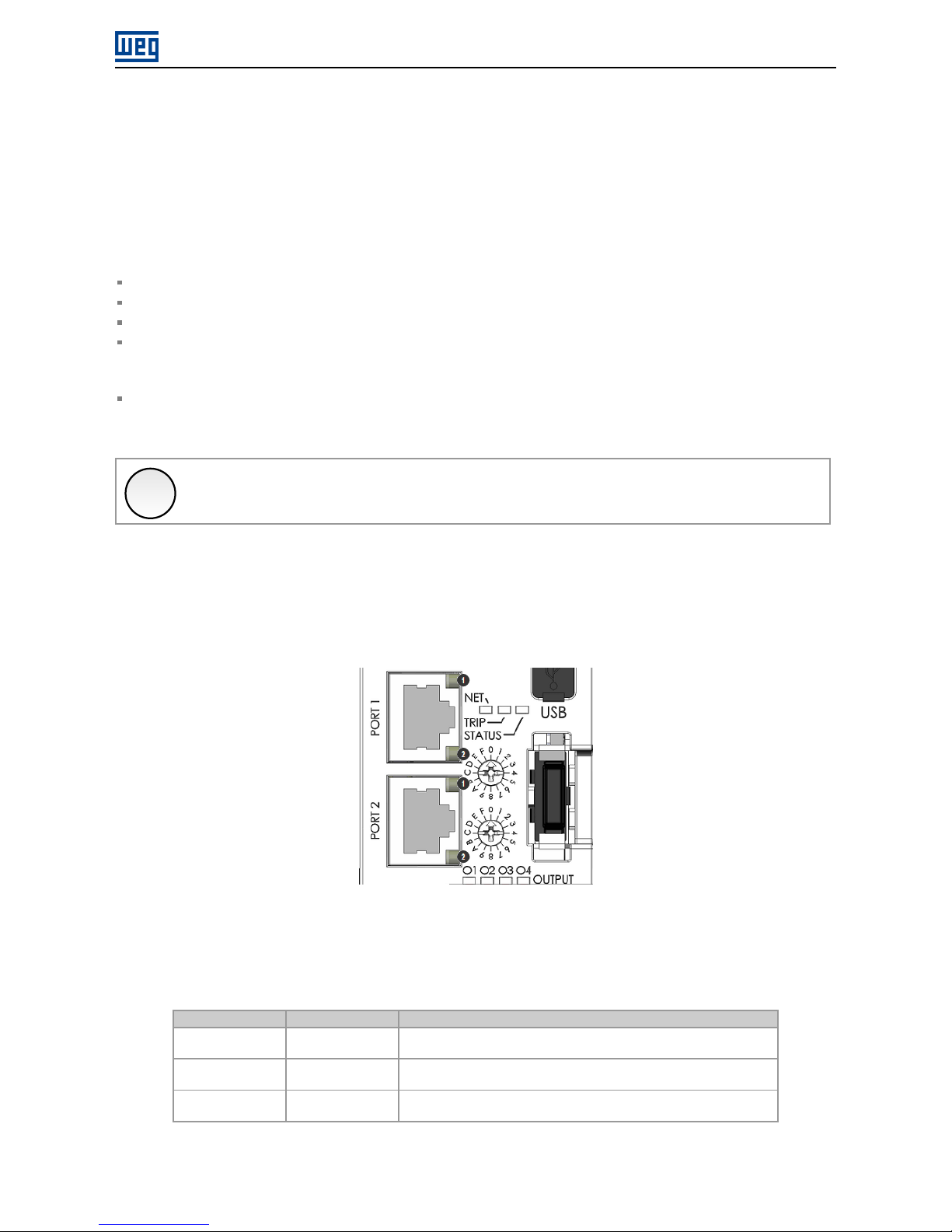
3.2 INDICATION LEDS
The smart relay SRW01-ETH has LEDs in the each Ethernet port connector (PORT1 and PORT2), besides a bicolor
diagnostics LED (NET).
Figure 3.1: Connectors and LEDs
Those LEDs have the following functions and indications:
Table 3.1: Indication LEDs
LED Color Function
NET Bicolor
(Green/Red)
Network status. See specific chapter of protocols for description of indications.
Link/Activity
100Mbps Ê
Green 100Mbps link and activity indication LED, one for each Ethernet port.
Link/Activity
10Mbps Ë
Amber 10Mbps link and activity indication LED, one for each Ethernet port.
SRW01-ETH | 8
Page 9

Interface Description
Table 3.2: LED 1 (green) - Link/Activity 100Mbps
Status Description
Off Without link or device turned OFF.
Green Ethernet link established but without activity.
Flashing Green Ethernet link established and with activity.
Table 3.3: LED 2 (amber) - Link/Activity 10Mbps
Status Description
Off Without link or device turned OFF.
Amber Ethernet link established but without activity.
Flashing Amber Ethernet link established and with activity.
SRW01-ETH | 9
Page 10

Network Installation
4 NETWORK INSTALLATION
This chapter presents recommendations related to equipment installation in an Ethernet network.
4.1 IP ADDRESS
Every equipment in an Ethernet network needs an IP address and subnet mask.
The IP addressing is unique in the network, and each equipment must have a different IP. The subnet mask is used
to define which IP address range is valid in the network.
For the smart relay SRW01-ETH, the programming of the IP address is made using parameters and the addressing
switches present in the product. The address configuration options depend on the protocol according to the product
model - Modbus TCP, EtherNet/IP or PROFINET IO. See the chapter about the desired protocol for the description
of these options.
4.2 COMMUNICATION RATE
The Ethernet interfaces of the SRW01-ETH smart relay can communicate using the 10 or 100 Mbps rates in half or
full duplex mode.
The baud rate is programmed at P0753.
X
NOTE!
It is important that, for each Ethernet connection made between two points, the baud rate and the
duplex mode are set to the same option. If the option AUTO is used in one of the points, you must
set the other point also to AUTO, or to half duplex mode.
For PROFINET IO interface, the baud rate is locked to 100 Mbps as required by the protocol.
4.3 CABLE
Recommended characteristics for the cable:
Standard Ethernet cable, 100Base-TX (FastEthernet), CAT 5e or higher.
Shielded cable.
Maximum length between devices: 100 m.
For installation, it is recommended the use of shielded Ethernet cables specific for use in industrial environment.
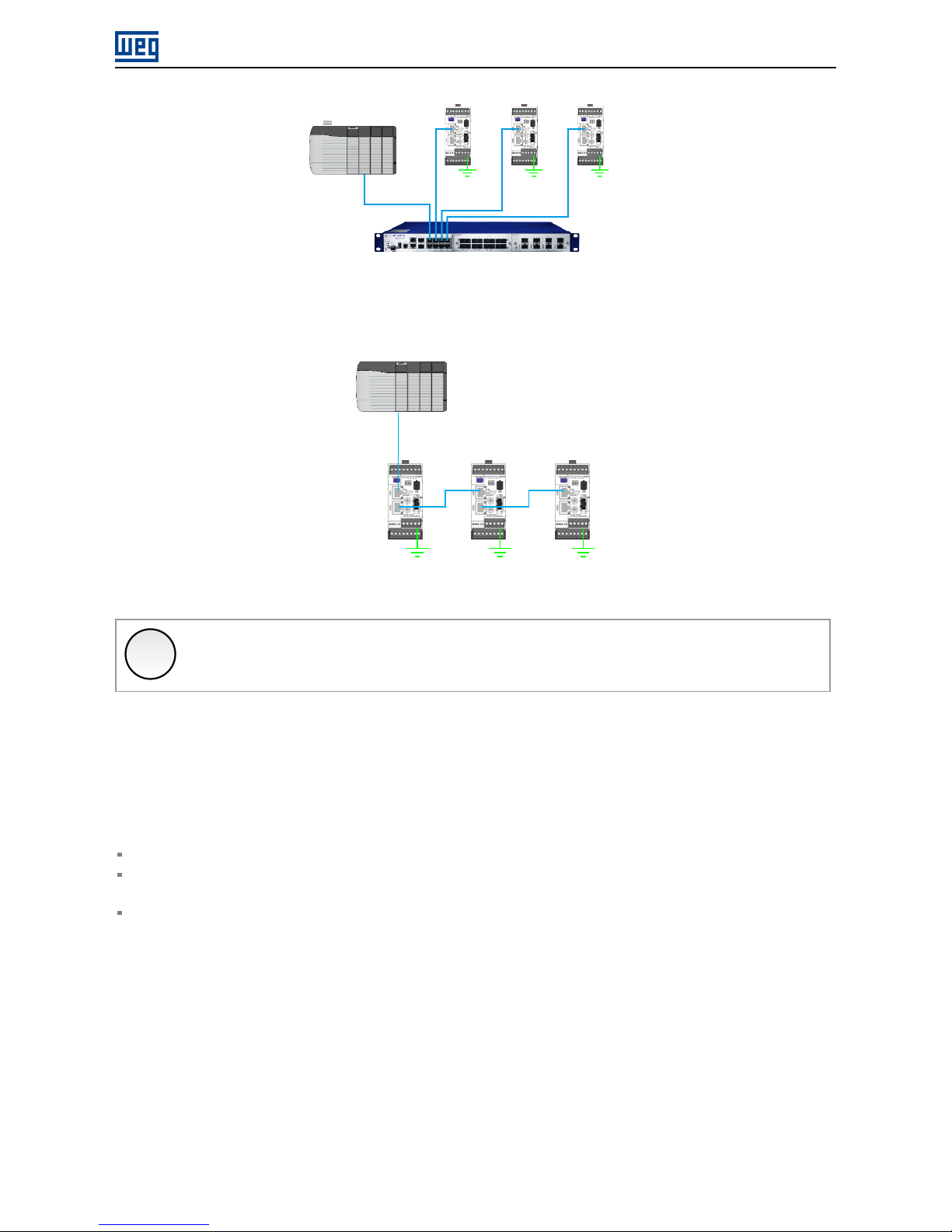
4.4 NETWORK TOPOLOGY
To connect SRW01-ETH smart relay in an Ethernet network, usually the star connection is made using an industrial
switch.
SRW01-ETH | 10
Page 11
Network Installation
Figure 4.1: Star topology
It is also possible to make the connection in daisy chain, allowing a topology equivalent to a bus.
Figure 4.2: Daisy chain topology
X
NOTE!
When the equipment is turned off, the built-in switch is also deactivated, preventing communication
with the subsequent equipment.
4.5 RECOMMENDATIONS FOR GROUNDING CONNECTION AND CABLE ROUTING
The correct connection with the ground decreases problems caused by interference in an industrial environment. The
following are some recommendations about grounding and cable routing:
Always use shielded twisted pair Ethernet cables and connectors with metallic housing.
Connect the equipment grounding via grounding terminal. Avoid the cable connection on multiple grounding
points, especially where there are grounds with different potentials.
Pass signal cables and communication cables in dedicated pathways. Prevent laying these cables next to power
cables.
SRW01-ETH | 11
Page 12

Programming
5 PROGRAMMING
Next, the SRW01-ETH smart relay parameters related to the Ethernet communication will be presented.
5.1 SYMBOLS FOR THE PROPERTIES DESCRIPTION
RO Read-only parameter
RW Read-write parameter
Sys System parameter, its value is updated when the ”PROG” key is pressed.
CFG Configuration parameter, it can be changed with motor stopped only
P0029 – VALUE OF ADDRESSING SWITCHES
Range: 0 to 255 Default: Properties: RO
Description:
It presents the addressing switch value identified at the power-up of the smart relay.
The two addressing switches, close to the SRW01-ETH Ethernet connectors, allow to program the expected IP
address or Station Name.
In order to obtain information about the possible configurations with switches, refer to item 4.1.
P0313 – ACTION IN CASE OF COMMUNICATION ERROR (FIELDBUS)
Range: 0 = Only Fault Indication
1 = The motor is turned off
2 = Motor is turned off and commands are reset
3 = It changes to Local
Default: 0
Properties: RW, Sys
Description:
It allows the selection of the action to be executed by the device, if it is controlled via network and a communication
error is detected.
Table 5.1: P0313 options
Option Description
0 = Only Fault Indication Fault indication only with no action taken. The indication of fault will be automatically
removed if the fault condition is cleared and the relay status are not either Trip or Error. If
the relay status is Trip or Error, it is mandatory to perform “error reset” in order to remove
the fault indication.
1 = The motor is turned off It switches the motor off, for the operation modes where this commands exists. It is
necessary to perform the error reset in order to remove the indication.
2 = Motor is turned off and
commands are reset
It switches the motor off and resets the commands. It is necessary to perform the error
reset in order to remove the indication.
3 = It changes to Local It changes to local mode, providing that the local/remote selection is programmed to
be executed via Fieldbus. The indication of fault will be automatically removed if the
fault condition is cleared and the relay status are not either Trip or Error. If the relay
status is Trip or Error, it is mandatory to perform “error reset” in order to remove the fault
indication.
The following events are considered communication errors:
SRW01-ETH | 12
Page 13

Programming
E0129: Ethernet Offline.
E0130: Ethernet interface access error.
E0131: Timeout on Modbus communication.
The actions described in this parameter are executed by means of the automatic writing of the selected actions in
the respective bits of the interface control words. Therefore, in order that the commands written in this parameter
be effective, it is necessary that the device be programmed to be controlled via the used network interface. This
programming is achieved by means of parameters P0220 to P0232.
P0680 – STATUS WORD
Range: 0000h ... FFFFh Default: Properties: RO
Description:
It allows the device status monitoring. Each bit represents a specific status:
Bit
15 14 13 12 11 10 9 8 7 6 5 4 3 2 1 0
Function
Reserved
Digital Output O4 Status
Digital Output O3 Status
Digital Output O2 Status
Digital Output O1 Status
Digital Input I16 Status
Digital Input I15 Status
Digital Input I14 Status
Digital Input I13 Status
Digital Input I12 Status
Digital Input I11 Status
Remote Mode
Motor On
Alarm/Fault
Trip
Error
SRW01-ETH | 13
Page 14

Programming
Table 5.2: P0680 indications
Bit Value/Description
Bit 0
Error
0: the relay is not in error condition.
1: the relay is in error condition.
Note: The error number can be read via the parameter P0016 – Current Error.
Bit 1
Trip
0: the relay is not in the trip condition.
1: the relay is in the trip condition.
Note: The trip fault number can be read via the parameter P0016 – Current Error.
Bit 2
Alarm/Fault
0: the relay is not in the alarm/fault condition.
1: the relay is in the alarm/fault condition.
Note: The alarm/fault number can be read via the parameter P0016 – Current Error.
Bit 3
Motor On
0: motor Off.
1: Motor On.
Bit 4
Remote Mode
0: the relay is in local mode.
1: the relay is in remote mode.
Bit 5
Digital Input I11 Status
0: I11 digital input is deactivated.
1: I11 digital input is activated.
Bit 6
Digital Input I12 Status
0: I12 digital input is deactivated.
1: I12 digital input is activated.
Bit 7
Digital Input I13 Status
0: I13 digital input is deactivated.
1: I13 digital input is activated.
Bit 8
Digital Input I14 Status
0: I14 digital input is deactivated.
1: I14 digital input is activated.
Bit 9
Digital Input I15 Status
0: I15 digital input is deactivated.
1: I15 digital input is activated.
Bit 10
Digital Input I16 Status
0: I16 digital input is deactivated.
1: I16 digital input is activated.
Bit 11
Digital Output O1 Status
0: O1 digital output is deactivated.
1: O1 digital output is activated.
Bit 12
Digital Output O2 Status
0: O2 digital output is deactivated.
1: O2 digital output is activated.
Bit 13
Digital Output O3 Status
0: O3 digital output is deactivated.
1: O3 digital output is activated.
Bit 14
Digital Output O4 Status
0: O4 digital output is deactivated.
1: O4 digital output is activated.
Bit 15 Reserved.
P0682 – CONTROL WORD
Range: 0000h ... FFFFh Default: 0000h
Properties: RW
Description:
It is the the smart relay Ethernet interface control word. This parameter can only be changed via Ethernet interface.
For the other sources (HMI, etc.) it behaves like a read-only parameter.
Actually, it represents the control word itself, whose data format varies according to the chosen operation mode
(P0202).
Each bit of this word represents a command that can be executed.
Bit
15 14 13 12 11 10 9 8 7 6 5 4 3 2 1 0
Function
Reserved
Digital Output O8 Value
Digital Output O7 Value
Digital Output O6 Value
Digital Output O5 Value
Digital Output O4 Value
Digital Output O3 Value
Digital Output O2 Value
Digital Output O1 Value
Remote
Reset
Command 3
Command 2
Command 1
SRW01-ETH | 14
Page 15

Programming
Table 5.3: P0682 bits function
Bit Value/Description
Bit 0
Command 1*
Varies according to the chosen operation mode (P0202).
Bit 1
Command 2*
Varies according to the chosen operation mode (P0202).
Bit 2
Command 3*
Varies according to the chosen operation mode (P0202).
Bit 3
Reset
0 → 1: when faulted (trip), it executes the relay reset.
Bit 4
Remote**
0: changes to local mode.
1: changes to remote mode.
Bit 5
Digital Output O1 Value***
0: deactivates the O1 digital output.
1: activates the O1 digital output.
Bit 6
Digital Output O2 Value***
0: deactivates the O2 digital output.
1: activates the O2 digital output.
Bit 7
Digital Output O3 Value***
0: deactivates the O3 digital output.
1: activates the O3 digital output.
Bit 8
Digital Output O4 Value***
0
: deactivates the O4 digital output.
1: activates the O4 digital output.
Bit 9
Digital Output O5 Value***
0: deactivates the O5 digital output.
1: activates the O5 digital output.
Bit 10
Digital Output O6 Value***
0: deactivates the O6 digital output.
1: activates the O6 digital output.
Bit 11
Digital Output O7 Value***
0: deactivates the O7 digital output.
1: activates the O7 digital output.
Bit 12
Digital Output O8 Value***
0: deactivates the O8 digital output.
1: activates the O8 digital output.
Bit 13...15 Reserved.
*In order to have those commands executed, it is necessary that the smart relay be in remote mode. Remote
Commands are equivalent to the commands via digital inputs I11, I12 and I13 and are used to drive the motor
depending on the operating mode selected in P0202.
**For the Local/Remote selection, it is necessary to program the parameter P0220 with the Fieldbus option.
***For the control of the digital outputs, it is necessary to program the parameters P0277 to P0284 with the Fieldbus
option.
SRW01-ETH | 15
Page 16

Programming
Table 5.4: Remote Commands of parameter P0682
Operation Mode Command
P0202 = 0
Transparent
Command 1 No function.
Command 2 No function.
Command 3 No function.
P0202 = 1
Overload Relay
Command 1 No function.
Command 2 No function.
Command 3 No function.
P0202 = 2
Direct Starter
Command 1 0 → 1 turns off the motor.
Command 2 0 → 1 turns on the motor.
Command 3 No function.
P0202 = 3
Reverse Starter
Command 1 0 → 1 turns off the motor.
Command 2 0 → 1 turns on the motor in forward direction.
Command 3 0 → 1 turns on the motor in reverse direction.
P0202 = 4
Star-Delta Starter
Command 1 0 → 1 turns off the motor.
Command 2 0 → 1 turns on the motor.
Command 3 No function.
P0202 = 5
Dahlander Starter
Command 1 0 → 1 turns off the motor.
Command 2 0 → 1 turns on the motor with high speed.
Command 3 0 → 1 turns on the motor with low speed.
P0202 = 6
Pole-Changing Starter
Command 1 0 → 1 turns off the motor.
Command 2 0 → 1 turns on the motor with high speed.
Command 3 0 → 1 turns on the motor with low speed.
P0202 = 7
PLC Mode
Command 1 No function.
Command 2 No function.
Command 3 No function.
P0751 – ETHERNET COMMUNICATION STATUS
Range: 0 = Setup
1 = Init
2 = Wait Comm
3 = Idle
4 = Data Active
5 = Error
6 = Reserved
7 = Exception
8 = Access Error
Default: -
Properties: RO
Description:
It allows identifying the Ethernet communication status.
Table 5.5: P0751 indications
Indication Description
0 = Setup Module identified, waiting configuration data (automatic).
1 = Init Module performing interface initialization procedure (automatic).
2 = Wait Comm Initialization finished, but no communication with master.
3 = Idle Communication with master established, but in Idle mode or Program mode.
4 = Data Active Communication with master established and performing normal I/O data handling. ”On-
line”.
5 = Error Communication error detected.
6 = Reserved Reserved
7 = Exception Major fault detected by the Ethernet interface. Requires interface reinitialization.
8 = Access error Major fault detected between device and Ethernet interface. Requires interface reinitia-
lization.
SRW01-ETH | 16
Page 17

Programming
X
NOTE!
For the product with Modbus TCP protocol, it will indicate status 4 (Data Active) from the receipt of
the first valid TCP Modbus telegram, and does not change state if the Modbus TCP communication
timeout occurs.
P0753 – ETHERNET BAUD RATE
Range: 0 = Auto
1 = 10Mbit/s, half duplex
2 = 10Mbit/s, full duplex
3 = 100Mbit/s, half duplex
4 = 100Mbit/s, full duplex
Default: 0
Properties: RW, Sys
Description:
It allows to set the desired baud rate for the Ethernet interface.
X
NOTE!
For the changes in this parameter be effective, the equipment must be powered off and on again,
or an update must be performed by P0899.
For PROFINET interface, the baud is locked to 100Mbit/s as required by the protocol.
P0756 – MODBUS TCP TIMEOUT
Range: 0.0 to 65.5 s Default: 0.0
Properties: RW, Sys
Description:
It allows programming a time limit for the detection of Ethernet offline error, for Modbus TCP protocol. If the SRW01ETH remains without receiving valid telegrams longer than the time programmed in this parameter, it will be considered
that a communication error has occurred, the alarm E0131 will be showed on the HMI and the option programmed
in P0313 will be executed.
After being powered up, the SRW01-ETH starts counting this time from the first received valid telegram. The value
0.0 disables this function.
X
NOTE!
For the changes in this parameter be effective, the equipment must be powered off and on again, or
an update must be performed by P0899.
P0760 – IP ADDRESS CONFIGURATION
Range: 0 = Parameters
1 = DHCP
2 = DCP
Default: 1
Properties: RW, Sys
Description:
It allows to choose how to set the IP address for the Ethernet interface.
SRW01-ETH | 17
Page 18

Programming
Table 5.6: P0760 options
Option Description
0 = Parameters The settings for IP address, sub-net mask and gateway shall be done by means of
parameters P0761 to P0769.
1 = DHCP Enables DHCP function. A DHCP server should set the IP address, sub-net mask and
gateway through network.
2 = DCP The IP address and other network configurations are received via DCP (PROFINET IO).
X
NOTE!
For the changes in this parameter be effective, the equipment must be powered off and on again, or
an update must be performed by P0899.
X
NOTE!
For Modbus TCP and EtherNet/IP protocols, this parameter is only used if the addressing switches on
the product for IP address setting are set to 0.
P0761 – IP ADDRESS 1
P0762 – IP ADDRESS 2
P0763 – IP ADDRESS 3
P0764 – IP ADDRESS 4
Range: 0 ... 255 Default: 192.168.0.10
Properties: RW, Sys
Description:
If P0760 = 0 (parameters), these parameters allow you to program the IP address of the Ethernet interface. For other
option of P0760, these parameters have no function.
Each parameter programs one octet of the IP address, where the P0761 is the most significant octet. The programmed IP address, then, has the format “P0761.P0762.P0763.P0764”.
X
NOTE!
For the changes in this parameter be effective, the equipment must be powered off and on again, or
an update must be performed by P0899.
X
NOTE!
For Modbus TCP and EtherNet/IP protocols, this parameter is only used if the addressing switches on
the product for IP address setting are set to 0.
P0765 – SUBNET CIDR
Range: 1 ... 31 Default: 24
Properties: RW, Sys
Description:
If P0760 = 0 (parameters), this parameters allow you to program the sub-net mask for the Ethernet interface. The
subnet mask can usually be programmed using a notation with 4 octets separated by dots, or CIDR notation, in
SRW01-ETH | 18
Page 19

Programming
which the value is the number of bits with value “1” in the subnet mask. For other option of P0760, this parameter
has no function.
The following table shows the allowed values for the CIDR notation and equivalent dot notation for the subnet mask:
Table 5.7: P0765 options
CIDR Sub-net mask CIDR Sub-net mask
1 128.0.0.0 17 255.255.128.0
2 192.0.0.0 18 255.255.192.0
3 224.0.0.0 19 255.255.224.0
4 240.0.0.0 20 255.255.240.0
5 248.0.0.0 21 255.255.248.0
6 252.0.0.0 22 255.255.252.0
7 254.0.0.0 23 255.255.254.0
8 255.0.0.0 24 255.255.255.0
9 255.128.0.0 25 255.255.255.128
10 255.192.0.0 26 255.255.255.192
11 255.224.0.0 27 255.255.255.224
12 255.240.0.0 28 255.255.255.240
13 255.248.0.0 29 255.255.255.248
14 255.252.0.0 30 255.255.255.252
15 255.254.0.0 31 255.255.255.254
16 255.255.0.0
X
NOTE!
For the changes in this parameter be effective, the equipment must be powered off and on again, or
an update must be performed by P0899.
X
NOTE!
For Modbus TCP and EtherNet/IP protocols, this parameter is only used if the addressing switches on
the product for IP address setting are set to 0.
P0766 – GATEWAY 1
P0767 – GATEWAY 2
P0768 – GATEWAY 3
P0769 – GATEWAY 4
Range: 0 ... 255 Default: 0.0.0.0
Properties: RW, Sys
Description:
If P0760 = 0 (parameters), these parameters allow you to program the IP address of the default gateway for the
Ethernet interface. For other option of P0760, these parameters have no function.
Each parameter programs one octet of the gateway address, where the P0766 is the most significant octet. The
programmed gateway IP address, then, has the format “P0766.P0767.P0768.P0769”.
X
NOTE!
For the changes in this parameter be effective, the equipment must be powered off and on again, or
an update must be performed by P0899.
SRW01-ETH | 19
Page 20

Programming
X
NOTE!
For Modbus TCP and EtherNet/IP protocols, this parameter is only used if the addressing switches on
the product for IP address setting are set to 0.
P0800 ... P0819 – READ WORDS #1 ... #20
Range: 0 to 65535 Default: Properties: RW, Sys
Description:
These parameters allow programming the number of read words (inputs: slave → master), as well as the content of
each word.
Each of words #1 to #20 can be programmed by the user. By using these parameters it is possible to program
the number of another parameter whose content must be made available at the network master input area. If, for
instance, one wants to read from the SRW01-ETH smart relay the motor current in Amps, one must program the
value 3 in one of these parameters, because the parameter P0003 is the one that contains this information. It is
worthwhile to remind that the value read from any parameter is represented with a 16 bit word. Even if the parameter
has decimal resolution, the value is transmitted without the indication of the decimal places. E.g., if the parameter
P0003 has the value 4.7A, the value supplied via the network will be 47.
It will be added to the input area the words programmed in these parameters if the contents programmed for these
parameters is different from zero. The first parameter set to zero disables the use of itself and the other parameters
in the sequence. For example, if you set:
P0800 = 680 (P0680 = status)
P0801 = 3 (P0003 = current)
P0802 = 0 (disabled)
Only two read words (state and current) will be communicated with the master. The same number of words programmed into the equipment must be programmed in the master when configuring the network.
Modbus TCP protocol allows to access each parameter directly, and do not distinguish cyclic and acyclic data.
X
NOTE!
For the changes in these parameters be effective, the equipment must be powered off and on again,
or an update must be performed by P0899.
P0850 ... P0869 – WRITE WORDS #1 ... #20
Range: 0 to 65535 Default: Properties: RW, Sys
Description:
These parameters allow programming the number of write words (outputs: master → slave), as well as the content
of each word.
The words #1 to #20 can be programmed by the user. By using these parameters it is possible to program the number
of another parameter whose content must be made available at the network master output area. If, for instance, one
wants to write to the SRW01-ETH smart relay the control word, one must program the value 682 in one of these
parameters, because the parameter P0682 is the one to program this information. It is worthwhile to remind that the
value written from any parameter is represented with a 16 bit word. Even if the parameter has decimal resolution, the
SRW01-ETH | 20
Page 21

Programming
value is transmitted without the indication of the decimal places. E.g., if a parameter has the value 5.0s, the value
supplied via the network will be 50.
It will be added to the output area the words programmed in these parameters if the contents programmed for these
parameters is different from zero. The first parameter set to zero disables the use of itself and the other parameters
in the sequence. For example, if you set:
P0850 = 682 (P0682 = control)
P0851 = 0 (disabled)
Only one write word (control) will be communicated with the master. The same number of words programmed into
the equipment must be programmed in the master when configuring the network.
Modbus TCP protocol allows to access each parameter directly, and do not distinguish cyclic and acyclic data.
X
NOTE!
For the changes in these parameters be effective, the equipment must be powered off and on again,
or an update must be performed by P0899.
P0899– UPDATE ETHERNET CONFIGURATION
Range: 0 = Normal Operation
1 = Update configuration
Default: 0
Properties: CFG, Sys
Description:
It allows you to force a reset of the Ethernet interface, to update the settings made in the device parameters. When
setting this parameter to “1”, the Ethernet interface is restarted, resulting in loss of communication during this process.
After the process is complete, the parameter switch automatically to “0”.
SRW01-ETH | 21
Page 22

Modbus TCP
6 MODBUS TCP
This chapter shows operating characteristics of the smart relay SRW01-ETH for communication as Modbus TCP
server.
6.1 IP ADDRESS CONFIGURATION
The two addressing switches, close to the Ethernet connectors of the SRW01-ETH, allow setting the configuration
of the IP adress, when Switch Ê represents the most significant digit and Switch Ë the least significant digit.
Figure 6.1: Addressing switches
Table 6.1: Addressing switches configuration for Modbus TCP
Values for switches 1 and2Configuration
00h It configures the interface to use the parameters values P0760 ... P0769.
01h ... FEh The combination of switches 1 and 2 form the value to configure the last
digit of the IP address (192.168.0.x with subnet mask 255.255.255.0,
gateway and DHCP disabled).
FFh Reserved.
X
NOTE!
For the changes in this parameter be effective, the equipment must be powered off and on again, or
an update must be performed by P0899.
6.2 INDICATION LEDS
In addition to the LEDs next to the Ethernet connectors, the smart relay SRW01-ETH has the NET LED on the front
of the product to indicate network status. For the Modbus TCP protocol, it has the following indications:
Table 6.2: Net LED
State Description
Off No power or no IP address.
Green, solid Connection established.
Green, flashing Waiting for connections.
Red, solid Fatal error (interface must be reinitialized).
SRW01-ETH | 22
Page 23

Modbus TCP
6.3 AVAILABLE FUNCTIONS
In the Modbus specification are defined the functions used to access different types of data. In the SRW01-ETH, in
order to access those data the following services (or functions) have been made available:
Table 6.3: Supported Modbus Functions
Code Name Description
01 Read Coils Reading of bit blocks of the coil type.
02 Read Discrete Inputs Reading of bit blocks of the discrete input type.
03 Read Holding Registers Reading of register blocks of the holding register type.
04 Read Input Registers Reading of register blocks of the input register type.
05 Write Single Coil Writing in a single bit of the coil type.
06 Write Single Register Writing in a single register of the holding type.
15 Write Multiple Coils Writing in bit blocks of the coil type.
16 Write Multiple Registers Writing in register blocks of the holding register type.
43 Read Device Identification Identification of the device model.
6.4 MEMORY MAP
The smart relay SRW01-ETH has different types of data accessible through the Modbus communication. These data
are mapped at data addresses and access functions as described in the following items.
6.4.1 Parameters
The SRW01-ETH Modbus communication is based on the reading/writing of the equipment parameters. All the drive
parameters list is made available as 16-bit holding registers type. The data addressing is done with the offset equal
to zero, which means that the parameter number corresponds to the register number. The following table illustrates
the parameters addressing, which can be accessed as holding register:
Table 6.4: Parameters Access - Holding Registers
Parameter Modbus data address (decimal)
P0000 0
P0001 1
.
.
.
.
.
.
P0100 100
.
.
.
.
.
.
It is necessary to know the device list of parameters to be able to operate the equipment. Thus, it is possible to
identify what data are needed for the status monitoring and the control of the functions. The main parameters are:
Monitoring (reading):
P0680 (holding register 680): Status word
Command (writing):
P0682 (holding register 682): Control Word
SRW01-ETH | 23
Page 24

Modbus TCP
Refer to the user’s guide for a complete parameter list of the equipment.
X
NOTE!
All the parameters are treated as holding registers. Depending on the master that is used, those
registers are referenced starting from the base address 40000 or 4x. In this case, the address
that must be programmed in the master for a parameter is the address showed in the table above
added to the base address. Refer to the master documentation to find out how to access holding
registers.
It should be noted that read-only parameters can only be read from the equipment, while other
parameters can be read and written through the network.
6.4.2 Memory Markers
Besides the parameters, other types of data as bit markers, word or float, can also be accessed using the Modbus
protocol. Those markers are used mainly by the ladder programming function, available for the SRW01-ETH. Refer
to the WLP software documentation for the description of those markers, as well as for the addresses via Modbus.
6.5 COMMUNICATION ERRORS
Communication errors may occur in the transmission of telegrams, as well as in the contents of the transmitted
telegrams. Transmission and connection errors are directly processed by the Ethernet interface and by the TCP/IP
protocol.
In the event of a successful reception, during the treatment of the telegram, the server may detect problems and send
an error message, indicating the kind of problem found:
Table 6.5: Error codes for Modbus
Error Code Description
1 Invalid function: the requested function is not implemented for the equip-
ment.
2 Invalid data address: the data address (register or bit) does not exist.
3 Invalid data value:
Value out of the allowed range.
Writing on data that cannot be changed (read only register or bit).
X
NOTE!
It is important that it be possible to identify at the client what type of error occurred, in order to be able
to diagnose problems during the communication.
6.6 STARTUP GUIDE
The following items describe main steps for SRW01-ETH commissioning using the Modbus TCP protocol. These
steps represent an example of use. Refer to specific chapters for details on the steps.
SRW01-ETH | 24
Page 25

Modbus TCP
6.6.1 Installing the Product on an Ethernet Network
1. Connect the Ethernet cable to the device, considering the recommended instructions in network installation,
as described in item 4:
Use shielded cable.
Properly ground network equipment.
Avoid laying communication cables next to power cables.
6.6.2 Configuring the Drive
1. Follow the recommendations described in the user’s manual to program the device parameters related to motor
settings, desired operation mode, I/O signs, etc.
2. Program command sources as desired for application.
3. Program communication parameters such as DHCP, IP address, baud rate, etc.
4. Program the timeout for Modbus TCP communication in parameter P0756.
5. Define which parameters will be read and written at SRW01-ETH smart relay, based on its parameter list. It is
not necessary to define I/O words. The Modbus TCP protocol enables direct access to any device parameter,
and does not distinguish between cyclic and acyclic data. The main parameters that can be used to control
the device, we can mention:
P0680 - Status Word
P0682 - Control Word
6. If necessary, restart the Ethernet interface using P0899.
6.6.3 Configuring the Master
The way you do the network setup is highly dependent on the network master and the network configuration tool.
It is important to know the tools used to perform this activity. In general, the following steps are required to perform
the network configuration.
1. Program the master to read and write holding registers, based on the defined equipment parameters to read
and write. The register number is based on the parameter number, as shown in table 6.4.
2. It is recommended that reading and writing are done in a cyclic manner, allowing detection of communication
errors by timeout.
6.6.4 Communication Status
Once you install the network and program the master, you can use the LEDs and equipment parameters to identify
some states related to communication.
The LEDs ”NET” and ”Link” provide information about the state of the interface and communication.
The parameter P0751 indicates the status of communication between the device and the network master.
The network master must also provide information about communication with slave.
SRW01-ETH | 25
Page 26

Modbus TCP
6.6.5 Operation Using Process Data
Once communication is established, data is written and read by the Modbus TCP network master automatically.
Using these parameters, the master is able to control the equipment and monitor its operation. It is important to
know the device parameters to program the master as desired for the application.
SRW01-ETH | 26
Page 27

EtherNet/IP
7 ETHERNET/IP
Following it shows operating characteristics of the SRW01-ETH smart relay using the for EtherNet/IP communication.
7.1 IP ADDRESS CONFIGURATION
The two addressing switches, close to the Ethernet connectors of the SRW01-ETH, allow setting the configuration
of the IP adress, when Switch Ê represents the most significant digit and Switch Ë the least significant digit.
Figure 7.1: Addressing switches
Table 7.1: Addressing switches configuration for EtherNet/IP
Values for switches 1 and2Configuration
00h It configures the interface to use the parameters values P0760 ... P0769.
01h ... FEh The combination of switches 1 and 2 form the value to configure the last
digit of the IP address (192.168.0.x with subnet mask 255.255.255.0,
gateway and DHCP disabled).
FFh Reserved.
X
NOTE!
For the changes in this parameter be effective, the equipment must be powered off and on again, or
an update must be performed by P0899.
7.2 INDICATION LEDS
In addition to the LEDs next to the Ethernet connectors, the smart relay SRW01-ETH has the NET LED on the front
of the product to indicate network status. For the EtherNet/IP protocol, it has the following indications:
Table 7.2: Net LED
State Description
Off No power or no IP address.
Green, solid Connection established.
Green, flashing Waiting for connections.
Red, solid Duplicate IP address, or fatal error (interface must be reinitialized).
Red, flashing One or more I/O connection timed out.
SRW01-ETH | 27
Page 28

EtherNet/IP
7.3 CYCLIC DATA
Cyclic data is the data normally used for status monitoring and equipment control. For EtherNet/IP protocol, the
interface supports an I/O connection that allows communication up to 20 input words and 20 output words.
It is necessary the configuration to be made both at the slave and master.
7.4 ACYCLIC DATA
In addition to the cyclic data, the interface also provides acyclic data via explicit messaging. Using this type of communication, you can access any equipment parameter. Access to this type of data is commonly done using instructions
for reading or writing data, which should indicate the class, instance, and attribute to the desired parameter. The
following table describes how to address the parameters for SRW01-ETH smart relay.
Table 7.3: Parameter Addressing
Parameter Class Instance Atribute
P0001 162 (A2h) 1 5
P0002 162 (A2h) 2 5
P0003 162 (A2h) 3 5
.
.
.
.
.
.
.
.
.
.
.
.
P0400 162 (A2h) 400 5
.
.
.
.
.
.
.
.
.
.
.
.
The data is transmitted as an integer value, without the indication of the decimal places.
7.5 EDS FILE
Each device on an EtherNet/IP network has an EDS configuration file, which contains information about the device
functions on the network. This file is used by a master or configuration software to program devices present at
EtherNet/IP network.
The EDS file is available from WEG website (http://www.weg.net). It is important to note if the EDS configuration file
is compatible with the firmware version of the SRW01-ETH smart relay.
7.6 MODBUS TCP CONNECTIONS
The device for EtherNet/IP also provides up to 2 Modbus TCP connections. These connections can be used for
parameterization, as well as access to markers and data used for SRW01-ETH ladder programming. The available
Modbus functions and communication data are described in item 6.
7.7 STARTUP GUIDE
Next it describes the main steps for commissioning SRW01-ETH smart relay on Ethernet network using EtherNet/IP
protocol. These steps represent an example of use. Refer to specific chapters for details on the steps.
SRW01-ETH | 28
Page 29

EtherNet/IP
7.7.1 Installing the Product on an Ethernet Network
1. Connect the Ethernet cable to the device, considering the necessary care in network installation, as described
in section 4:
Use shielded cable.
Properly ground the network devices.
Avoid laying communication cables next to power cables.
7.7.2 Configuring the Drive
1. Follow the recommendations described in the user’s manual to program the related to device settings, motor
parameters, desired functions for I/O signs, etc..
2. Program command sources as desired for application.
3. Program communication parameters such as DHCP, IP address, baud rate, etc.
4. Set the desired action for communication errors, through the P0313.
5. Set number of I/O words as well as the contents of each word using parameters P0800 to P0819 and P0850
to P0869.
6. If necessary, restart the Ethernet interface using P0899.
7.7.3 Configuring the Master
The way you do the network setup depends largely on the master and the configuration tool. It is important to know
these tools to perform this activity. In general, the following steps are required to do the network configuration.
1. Load the EDS file1to the list of devices in the network configuration tool.
2. Select SRW01-ETH smart relay from the available list of devices on the network configuration tool. This can be
done manually or automatically, if allowed by the tool.
3. For the master configuration, in addition to the IP address used by the EtherNet/IP module, you must indicate
the number of instances of I/O and the amount of data exchanged with the master in each instance. For the
communication module for EtherNet/IP, the following values must be programmed:
Input instance: 100
Output instance: 150
4. The EtherNet/IP device is described as “Generic Ethernet Module” on the device list. Using these settings you
can program the network master to communicate with the equipment.
7.7.4 Communication Status
Once you install the network and program the master, you can use the LEDs and equipment parameters to identify
some states related to communication.
The LEDs ”NET” and ”Link” provide information about the state of the interface and communication.
The parameter P0751 indicates the status of communication between the device and the network master.
The network master must also provide information about the communication with slave.
1
The EDS file is available from WEG website (http://www.weg.net). It is important to note if the EDS configuration file is compatible with the
firmware version of the SRW01-ETH smart relay.
SRW01-ETH | 29
Page 30

EtherNet/IP
7.7.5 Operation Using Process Data
Once the communication is established, the data mapped in the I/O area is automatically updated between master
and slave. Among the main parameters that can be used to control the device, we can mention:
P0680 - Status Word (read)
P0682 - Control Word (write)
It is important to know these parameters to program the master as desired for the application.
SRW01-ETH | 30
Page 31

PROFINET
8 PROFINET
Following it shows operating characteristics of the SRW01-ETH smart relay using the for PROFINET communication.
8.1 IP ADDRESS CONFIGURATION
In a PROFINET network, IP address programming is usually done through the network itself, instead of being locally
programmed in the product. In this case, you must program in the P0760 to option 2 (DCP). With this option, no local
product configuration will be used - IP address, subnet mask, DHCP or gateway. Configuration of these properties
must be received over the network using DCP commands. It is also possible to set the addressing switches to ’FF’
position, so that the IP address configuration is not made locally, only via network via DCP. To set the IP address
locally on the product - as well as other relevant parameters - you must use the parameters P0760 to P0769.
8.2 STATION NAME CONFIGURATION
In a PROFINET network, each equipment has a different Station Name, which is used to identify the equipment in the
network.
The two addressing switches, next to SRW01-ETH Ethernet connectors, allow you to program how to configure
the Station Name, where the switch Ê represents the most significant digit and the switch Ë represents the less
significant digit.
Figure 8.1:
Addressing Switches
Table 8.1: Addressing switches configuration for PROFINET IO
Values for switches 1 and2Configuration
00h Station Name: do not program the Station Name, and this configuration
must be done via network using the DCP protocol. Once programmed,
the Station Name value is saved to non-volatile memory, and remains
programmed even when the product is turned off.
IP address: IP address settings are made using the parameters P0760
to P0769.
01h ... FEh Station Name: the combination of switches 1 and 2 form the value to
configure the Station Name suffix. In this case, when powering the product, it will assume the Station Name ”SRW01-ETH-XY”, with ’X’ and ’Y’
being the value of switches 1 and 2 respectively (numbers ’1’ through ’9’
and letters ’A’ to ’F’).
IP address: IP address settings are made using the parameters P0760
to P0769.
FFh Station Name and IP Address are not programmed locally, and all confi-
guration must be done via network using the DCP protocol. Once programmed, the values are saved in non-volatile memory, and remain programmed even when the product is turned off.
SRW01-ETH | 31
Page 32

PROFINET
X
NOTE!
For the changes in this parameter be effective, the equipment must be powered off and on again, or
an update must be performed by P0899.
8.3 INDICATION LEDS
In addition to the LEDs next to the Ethernet connectors, the smart relay SRW01-ETH has the NET LED on the front
of the product to indicate network status. For the PROFINET IO protocol, it has the following indications:
Table 8.2: Net LED
State Description
Off No power or no connection with controller.
Green, solid Connection with controller established, controller in RUN mode.
Green, flashing Connection with controller established, controller in STOP mode.
8.4 CYCLIC DATA
Cyclic data is the data normally used for status monitoring and equipment control. For PROFINET protocol, the
interface supports an I/O connection that allows communication up to 20 input words and 20 output words.
It is necessary the configuration to be made both at the slave and master.
8.5 ACYCLIC DATA
In addition to the cyclic data, the PROFINET protocol also provides acyclic data, mainly used to communicate diagnoses and parameterization data. For the SRW01-ETH smart relay, the parameter list is available using this communication method.
The PROFINET protocol defines the following structure to address the components for network configuration:
AR (Application Relation)
API (Application Process Identifier)
Slot
Subslot
The AR and API are used to identify the Ethernet module during the network configuration steps. Slot/subslot are not
relevant for accessing acyclic data. Once the module is identified, the parameters are accessed indicating the index
and the data length:
Index: represents the parameter number;
Length: the length of data, in bytes. All device parameter are 2 bytes in length (Word).
The data is transmitted as an integer value, without the indication of the decimal places.
8.6 XML FILE – GSDML
Each device on an PROFINET network has an GSDML configuration file, which contains information about the device
functions on the network. This file is used by a master or configuration software to program devices present at
PROFINET network.
SRW01-ETH | 32
Page 33

PROFINET
The GSDML file is available from WEG website(http://www.weg.net). It isimportant to note if the GSDMLconfiguration
file is compatible with the firmware version of the SRW01-ETH smart relay.
8.7 MODBUS TCP CONNECTIONS
The device for PROFINET IO also provides up to 2 Modbus TCP connections. These connections can be used for
parameterization, as well as access to markers and data used for SRW01-ETH ladder programming. The available
Modbus functions and communication data are described in item 6.
8.8 STARTUP GUIDE
Next it describes the main steps for commissioningSRW01-ETH smart relay on Ethernet network using the PROFINET
protocol. These steps represent an example of use. Refer to specific chapters for details on the steps.
8.8.1 Installing the Product on an Ethernet Network
1. Connect the Ethernet cable to the device, considering the necessary care in network installation, as described
in section 4:
Use shielded cable.
Properly ground the network devices.
Avoid laying communication cables next to power cables.
8.8.2 Configuring the Drive
1. Follow the recommendations described in the user’s manual to program the related to device settings, motor
parameters, desired functions for I/O signs, etc..
2. Program command sources as desired for application.
3. Program communication parameters such as Station Name, etc.
4. Set the desired action for communication errors, through the P0313.
5. Set number of I/O words as well as the contents of each word using parameters P0800 to P0819 and P0850
to P0869.
6. If necessary, restart the Ethernet interface using P0899.
8.8.3 Configuring the Master
The way you do the network setup depends largely on the master and the configuration tool. It is important to know
these tools to perform this activity. In general, the following steps are required to do the network configuration.
1. Load the GSDML file2to the list of devices in the network configuration tool.
2. Select SRW01-ETH smart relay from the available list of devices on the network configuration tool. This can be
done manually or automatically, if allowed by the tool.
3. For the master configuration, you must indicate the number of I/O words exchanged with the master. It is
necessary to select word by word, first selecting all input words and then all output words.
2
The GSDML file is available from WEG website (http://www.weg.net). It is important to note if the GSDML configuration file is compatible with
the firmware version of the SRW01-ETH smart relay.
SRW01-ETH | 33
Page 34

PROFINET
4. The PROFINET device is recognized as ”SRW01-ETH”, at the ”General” category. Using these settings you
can program the network master to communicate with the equipment.
8.8.4 Communication Status
Once you install the network and program the master, you can use the LEDs and equipment parameters to identify
some states related to communication.
The LEDs ”NET” and ”Link” provide information about the state of the interface and communication.
The parameter P0751 indicates the status of communication between the device and the network master.
The network master must also provide information about the communication with slave.
8.8.5 Operation Using Process Data
Once the communication is established, the data mapped in the I/O area is automatically updated between master
and slave. Among the main parameters that can be used to control the device, we can mention:
P0680 - Status Word (read)
P0682 - Control Word (write)
It is important to know these parameters to program the master as desired for the application.
SRW01-ETH | 34
Page 35

WEB Server
9 WEB SERVER
Besides the communication protocol, the Ethernet interface also provides a WEB server with a simple HTML page
to access SRW01-ETH smart relay data. If the IP address is known, you can use a web browser by typing the IP
address in the browser address bar, and it will present a web page with links to interface settings and device data.
Figure 9.1:
WEB page for interface configuration
In the interface settings, it presents several fields for programming the IP address, subnet, DHCP, among others. The
parameter list of the equipment can also be accessed through the WEB browser via ”Parameter Data” link. This list
is presented in a simplified format, with only the integer values, with no indication of decimal places.
SRW01-ETH | 35
Page 36

Faults and Alarms
10 FAULTS AND ALARMS
E0129 - ETHERNET OFFLINE
Description:
Indicates communication failure between the slave and the network controller.
Actuation:
It occurs when, once established communication between the slave and the network master, there is an interruption
in this communication. The method for detecting the interruption of communication depends on the network:
EtherNet/IP: timeout in I/O connection, or master goes to IDLE state.
PROFINET: timeout on the cyclic communication between master and slave, or master goes to STOP state.
In this case, the device will show in the HMI E0129 message. This indication will automatically disappear at the
moment when the communication is reestablished.
Possible Causes/Correction:
Verify whether the network master is properly configured and operating normally.
Search for short-circuit or bad contact in the communication cables.
Verify the entire network installation – cable laying, grounding.
E0130 - ETHERNET INTERFACE ACCESS ERROR
Description:
Indicates internal error in data exchange between SRW01-ETH smart relay and Ethernet interface.
Actuation:
It occurs when the control board can not exchange data with the Ethernet interface or when the Ethernet interface
identifies some internal error.
In this case, the device will show in the HMI an alarm message E0130. Is is necessary to restart the Ethernet interface,
power cycling the product or using P0899.
Possible Causes/Correction:
Restore the factory configuration, and then perform the device parametrization again.
Hardware errors caused by the improper handling or installation of the product can cause this error. If possible,
test it by replacing the product.
E0131 - TIMEOUT ON MODBUS COMMUNICATION
Description:
It indicates fault in the Modbus TCP communication. Indicates that the equipment stopped receiving valid telegrams
for a period longer than the one programmed in P0756.
SRW01-ETH | 36
Page 37

Faults and Alarms
Actuation:
The parameter P0756 allows programming a period of time during which the equipment must receive at least one valid
telegram via the Ethernetinterface otherwise, it will be considered that there was any problem in the communication.
The time counting initiates after the reception of the first valid telegram.
After the communication timeout has been identified, the E0131 message will be showed on the HMI. When the
communication is reestablished, the error indication will be removed from the HMI.
Possible Causes/Correction:
Check network installation, broken cable or fault/poor contact on the connections with the network, grounding.
Make sure that theModbus TCP client sends telegrams to the equipment in intervals shorter than the programmed
in P0756.
Disable this function at P0756.
SRW01-ETH | 37
Page 38

WEG Drives & Controls - Automação LTDA.
Jaraguá do Sul – SC – Brazil
Phone 55 (47) 3276-4000 – Fax 55 (47) 3276-4020
São Paulo – SP – Brazil
Phone 55 (11) 5053-2300 – Fax 55 (11) 5052-4212
automacao@weg.net
www.weg.net
 Loading...