

Page 1
V SILVA
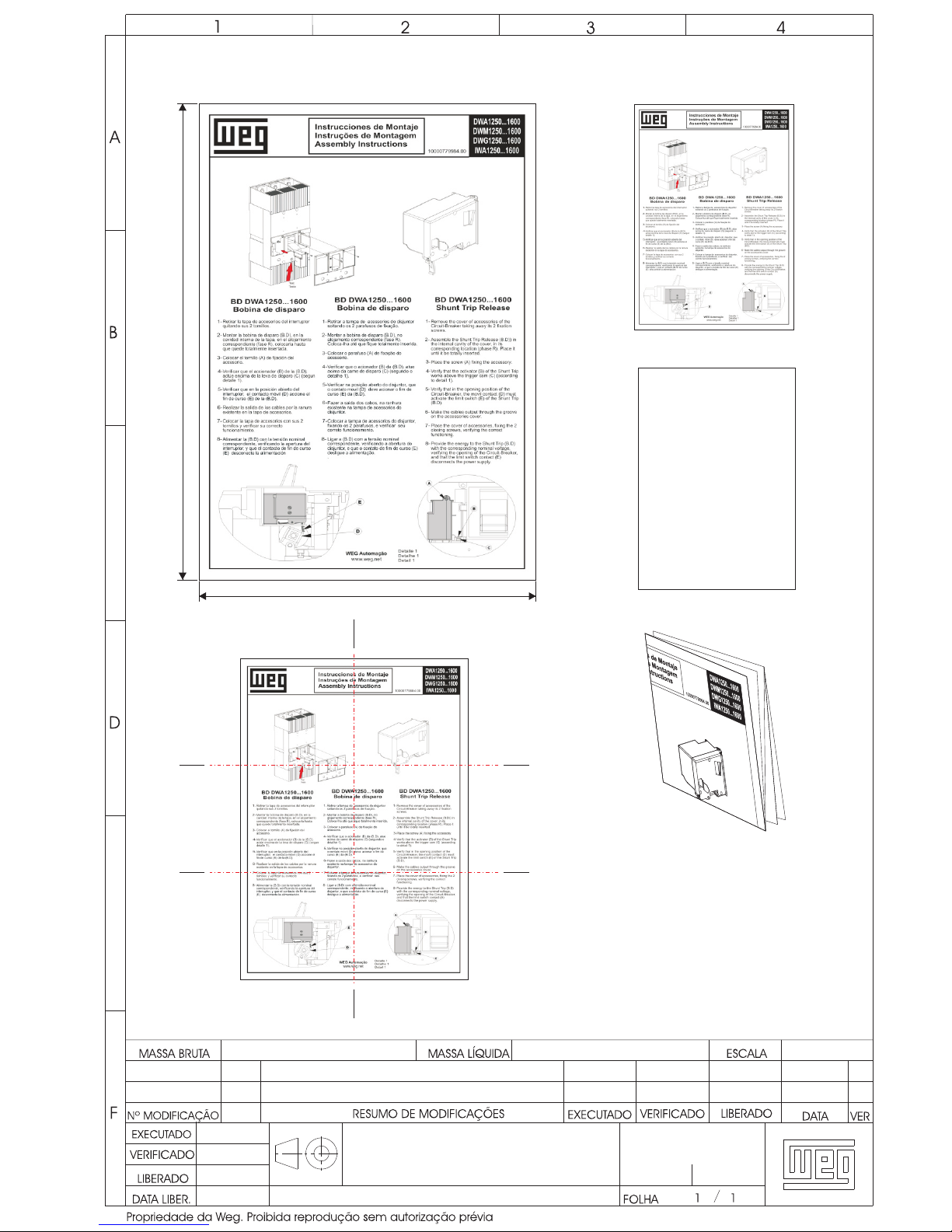
BULA BD WA1250...1600
Gramatura: 60g
Material: Papel Normal
FABIO
000
00
E
SOCRATES
20/07/09
10000779984
FRENTE
VERSO
DOBRAS
DIMENSIONAL
1ª DOBRA
3ª DOBRA
2ª DOBRA
- PARA VERIFICAÇÃO DE DADOS
UTILIZAR ARQUIVOS PARA IMPRESSÃO,
CONFORME PÁGINAS SEGUINTES.
-IMPRESSÃO: PRETO E BRANCO COM
ESCALA EM CINZA
-O DOCUMENTO DEVE SER DOBRADO
PELO FORNECEDOR.
-PARA IMPRESSÃO UTILIZAR ARQUIVOS
PARA IMPRESSÃO, CONFORME PÁGINAS
SEGUINTES.
210
297
Page 2
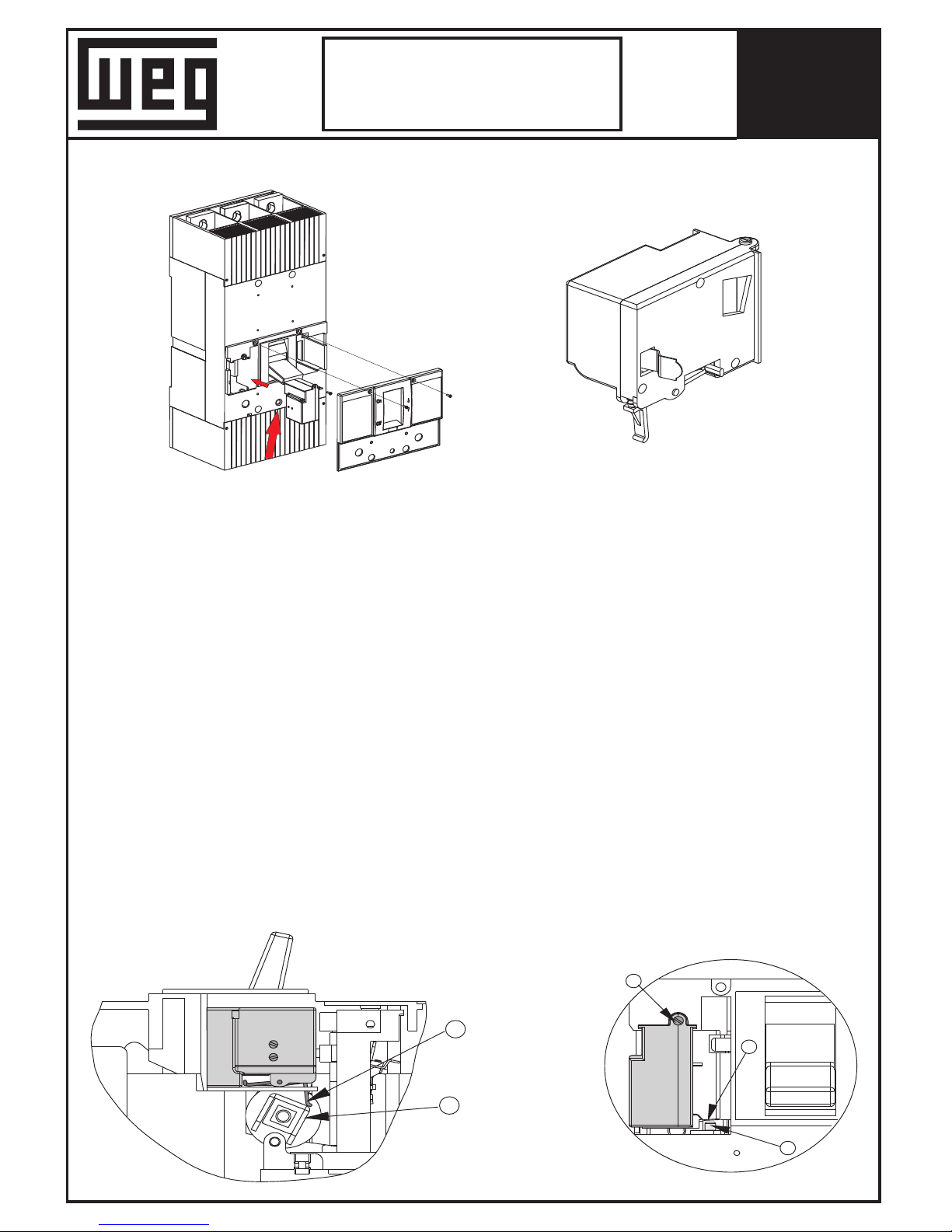
Retirar la tapa de accesorios del interruptor
quitando sus 2 tornillos.
Montar la bobina de disparo (B.D), en la
cavidad interna de la tapa, en el alojamiento
correspondiente (fase R), colocarla hasta
que quede totalmente insertada.
Colocar el tornillo (A) de fijación del
accesorio.
Verificar que el accionador (B) de la (B.D),
actúe encima de la leva de disparo (C) (segun
detalle 1).
Realizar la salida de los cables por la ranura
existente en la tapa de accesorios.
Colocar la tapa de accesorios con sus 2
tornillos y verificar su correcto
funcionamiento.
Verificar que en la posición abierto del
interruptor, el contacto móvil (D) accione el
fin de curso (E) de la (B.D).
Alimentar la (B.D) con la tensión nominal
correspondiente, verificando la apertura del
interruptor, y que el contacto de fin de curso
(E) desconecte la alimentación
Retirar a tampa de acessorios do disjuntor
soltando os 2 parafusos de fixação.
Montar a bobina de disparo (B.D), no
alojamento correspondente (fase R).
Coloca-lha até que fique totalmente inserida.
Colocar o parafuso (A) de fixação do
acessorio.
Verificar que o acionador (B) da (B.D), atue
acima da came de disparo (C) (segundo o
detalhe 1).
Verificar na posição aberto do disjuntor, que
o contato movil (D) deve acionar o fim de
curso (E) da (B.D).
Fazer a saida dos cabos, na ranhura
existente na tampa de acessorios do
disjuntor.
Colocar a tampa de acessorios do disjuntor,
fixando os 2 parafusos, e verificar seu
correto funcionamento.
Ligar a (B.D) com a tensão nominal
correspondente, verificando a abertura do
disjuntor, e que o contato de fim de curso (E)
desligue a alimentação.
.
1-
2-
3-
4-
5-
6-
7-
BD DWA1250...1600
Bobina de disparo
1-
2-
3-
4-
5-
6-
BD DWA1250...1600
Bobina de disparo
BD DWA1250...1600
Shunt Trip Release
Remove the cover of accessories of the
Circuit-Breaker taking away its 2 fixation
screws.
Assemble the Shunt Trip Release (B.D)) in
the internal cavity of the cover, in its
corresponding location (phase R). Place it
until it be totally inserted.
Place the screw (A) fixing the accessory.
Verify that the activator (B) of the Shunt Trip
works above the trigger cam (C) (according
to detail 1).
Verify that in the opening position of the
Circuit-Breaker, the movil contact (D) must
activate the limit switch (E) of the Shunt Trip
(B.D).
Make the cables output through the groove
on the accessories cover.
Place the cover of accessories, fixing the 2
closing screws, verifying the correct
functioning.
Provide the energy to the Shunt Trip (B.D)
with the corresponding nominal voltage,
verifying the opening of the Circuit-Breaker,
and that the limit switch contact (E)
disconnects the power supply.
1-
2-
3-
4-
5-
6-
7-
D
E
C
B
A
7-
8-
8-
8-
Test
Teste
Detalle 1
Detalhe 1
Detail 1
DWA
DWM1250...1600
DWG1250...1600
IWA1250...1600
1250...1600
Instrucciones de Montaje
Instruções de Montagem
Assembly Instructions
WEG Automação
www.weg.net
10000779984.00
 Loading...