

Page 1

External Power Supply for Control in
24 Vdc - KVDC-CFW11-2
Fuente de Alimentación Externa para
Control en 24 Vdc - KVDC-CFW11-2
Fonte de Alimentação Externa para
Controle em 24 Vdc - KVDC-CFW11-2
CFW-11/CFW70X
Installation Guide
Guía de Instalación
Guia de Instalação
Motors | Automation | Energy | Transmission & Distribution | Coatings
Page 2

Page 3

Summary/Índice
EnglishEspañolPortuguês
SUMMARY
1 INVERTER MODELS TO BE USED WITH ........................................5
2 BULLETIN OF MATERIALS ...............................................................5
3 PROCEDURES TO INSTALL THE KIT ON THE INVERTER ............7
3.1 FRAME SIZES D, F, G AND H................................................................. 7
4 LABEL .............................................................................................. 20
5 CHECK AFTER INSTALLATION .................................................... 20
ÍNDICE
1 CONVERTIDORES COMPATIBLES ................................................21
2 LISTA DE MATERIALES ..................................................................21
3 PROCEDIMIENTOS PARA INSTALAR EL KIT EN EL
CONVERTIDOR.................................................................................. 23
3.1 TAMAÑOS D, F, G Y H ..........................................................................23
4 ETIQUETA ....................................................................................... 36
5 INSPECCIÓN TRAS LA INSTALACIÓN ........................................ 36
ÍNDICE
1 INVERSORES COMPATÍVEIS .........................................................37
2 LISTA DE MATERIAIS ......................................................................37
3 PROCEDIMENTOS PARA INSTALAR O KIT NO INVERSOR ...... 39
3.1 MECÂNICAS D, F, G E H .......................................................................39
4 ETIQUETA ........................................................................................52
5 INSPEÇÃO APÓS A INSTALAÇÃO .................................................52
Page 4

Page 5
CFW-11/CFW70X | 5
External Power Supply for Control in 24 Vdc - KVDC-CFW11-2
English
NOTE!
This guide provides information for the installation of KVDC kit on the CFW-11
inverter without the suffix W (CFW-11) or W1 (CFW70X) in their description.
The KVDC-CFW11-2 is an optional component of the inverter, therefore, it cannot be sold to
end users or integrators separately.
It must always be installed by the WEG branch or WEG distributor, otherwise, the end user will
lose the warranty for opening the inner parts of the inverter.
1 INVERTER MODELS TO BE USED WITH
Applicable to the following models:
CFW-11 frame size D 690 V.
CFW70X frame size D 600 V.
CFW-11 frame sizes F, G and H.
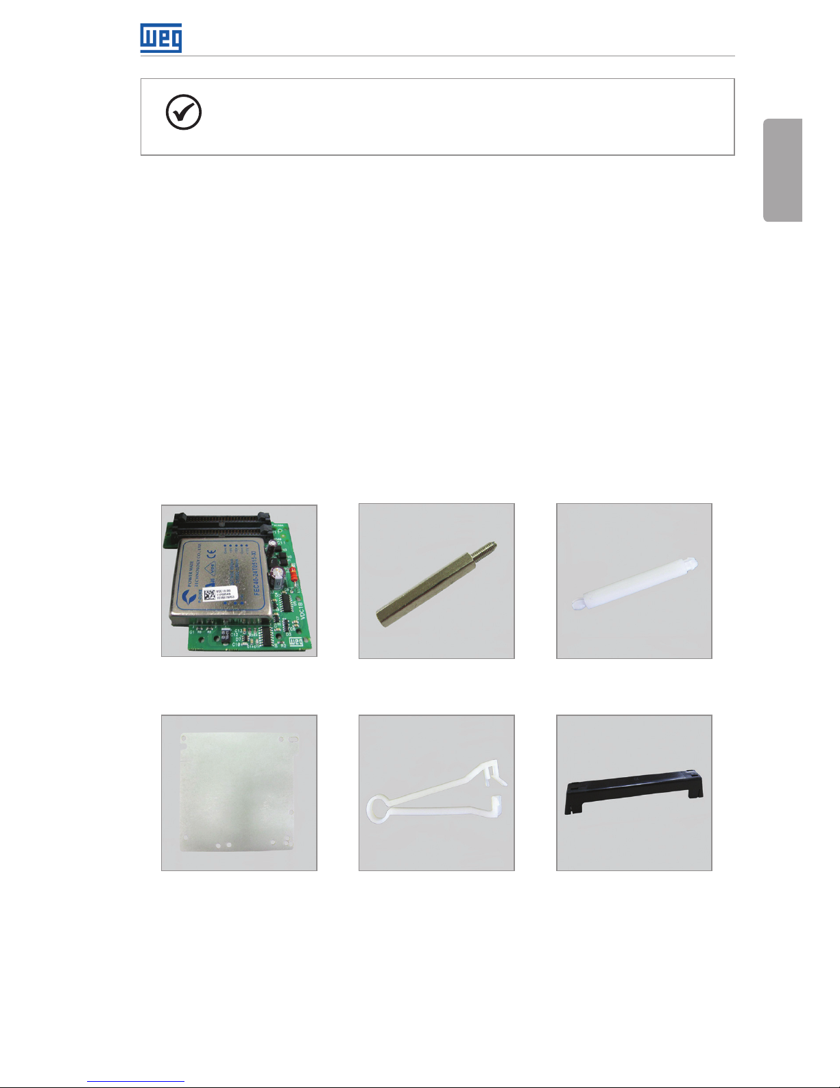
2 BULLETIN OF MATERIALS
(a) VDCx Electronic Board (b) Metal Spacers (c) Plastic spacers
(d) Insulation for the board (e) Clamp for ribbon-cable
(f) Plastic covers for
ribbon-cable connector
Page 6
6 | CFW-11/CFW70X
External Power Supply for Control in 24 Vdc - KVDC-CFW11-2
English
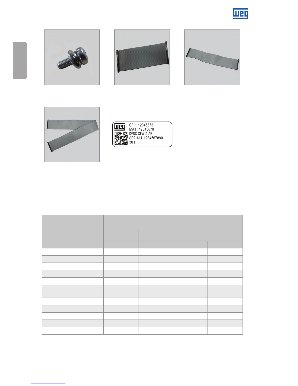
(g) M3 Screw (h) Ribbon-cable 160 mm (i) Ribbon-cable 260 mm
(j) Ribbon-cable 533 mm (k) Labels
Figure 1: Content of KVDC-CFW11-2 kit
Select the parts to be assembled on the inverter according to table 1; there are differences
according to the models.
Table 1: Items to be assembled according to the inverter model
Description
Quantity by Inverter Model1 (UN)
CFW-11/
CFW70X
CFW-11
Frame Size D Frame Size F Frame Size G Frame Size H
VDCx Electronic Board (a) 1 1 1 1
Metal spacer 28 mm (b) 2 3 3 2
Plastic spacer 28 mm (c) 2 1 1 2
Insulation for the board (d) 1 1 1 1
Clamp for ribbon-cable (e) 1 1 1 1
Plastic cover for ribbon-cable
connector (f)
2 2 2 2
M3 Screw2 (g) 2 3 3 2
Ribbon-cable 160 mm (h) 1 - - 1
Ribbon-cable 260 mm (i) - 1 - -
Ribbon-cable 533 mm (j) - - 1 1
Label (k) 2 2 2 2
Notes:
1 For information on the inverter frame size, check the technical specification table (table 8.1 on the user’s manual of the CFW-11 and tables
B.1 and B.2 on the user’s manual of the CFW700 / CFW701).
2 In case of replacement of the existing screw is needed.
Page 7
CFW-11/CFW70X | 7
External Power Supply for Control in 24 Vdc - KVDC-CFW11-2
English
3 PROCEDURES TO INSTALL THE KIT ON THE INVERTER
3.1 FRAME SIZES D, F, G AND H
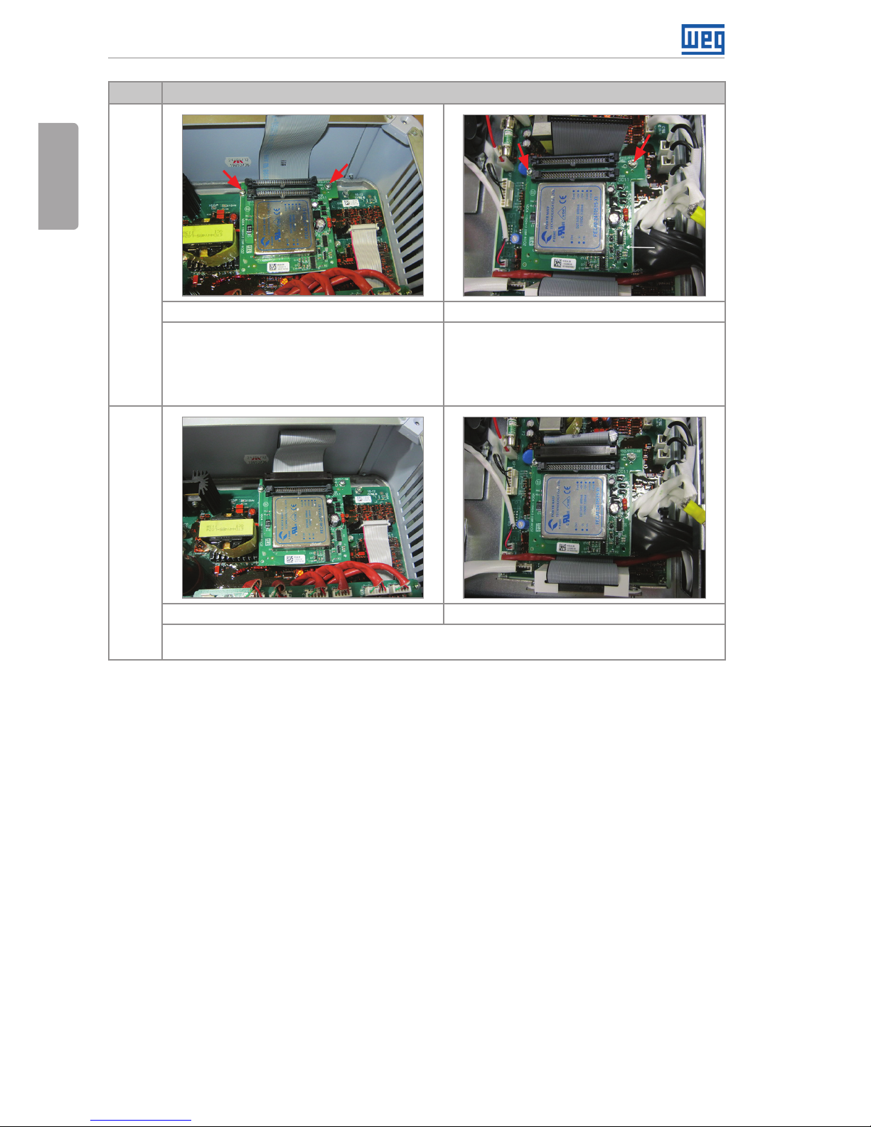
Step Actions/Instructions
1
Frame sizes D, F, G and H
Remove the HMI.
2
Frame sizes D, F, G and H
Loosen the two screws on the front cover of the control rack and remove it.
Page 8
8 | CFW-11/CFW70X
External Power Supply for Control in 24 Vdc - KVDC-CFW11-2
English
Step Actions/Instructions
3
Frame sizes D, F, G and H
Remove the two screws at the ends of the lower front cover and remove it.
4
Only frame size H
Remove the two screws at the ends of the upper cover and remove it.
5
Only frame sizes F and G
Remove the plastic cover on the connector and the ribbon-cable.
Be careful not to damage the components on the board close to the connector.
Page 9
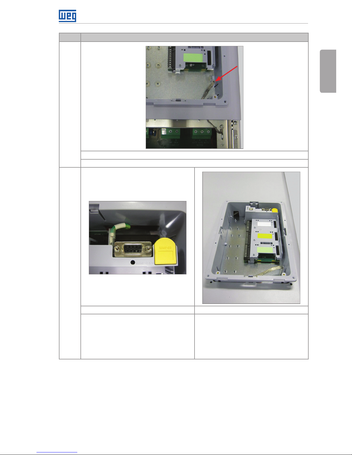
CFW-11/CFW70X | 9
External Power Supply for Control in 24 Vdc - KVDC-CFW11-2
English
Step Actions/Instructions
6
Only frame sizes D and H
Loosen the ground flexible braid on the screening plate.
7
Only frame sizes D and H Only frame sizes F and G
Remove the ground cable from XC98 of the
vertical board of the control board, the plastic
cover on the connector and the ribbon-cable.
Be careful not to damage the components on
the board close to the connector.
Note: this cable was added during the CE
certification. Some drives do not have this cable.
Using a screwdriver, release the control rack;
releasing the four locks.
Page 10
10 | CFW-11/CFW70X
External Power Supply for Control in 24 Vdc - KVDC-CFW11-2
English
Step Actions/Instructions
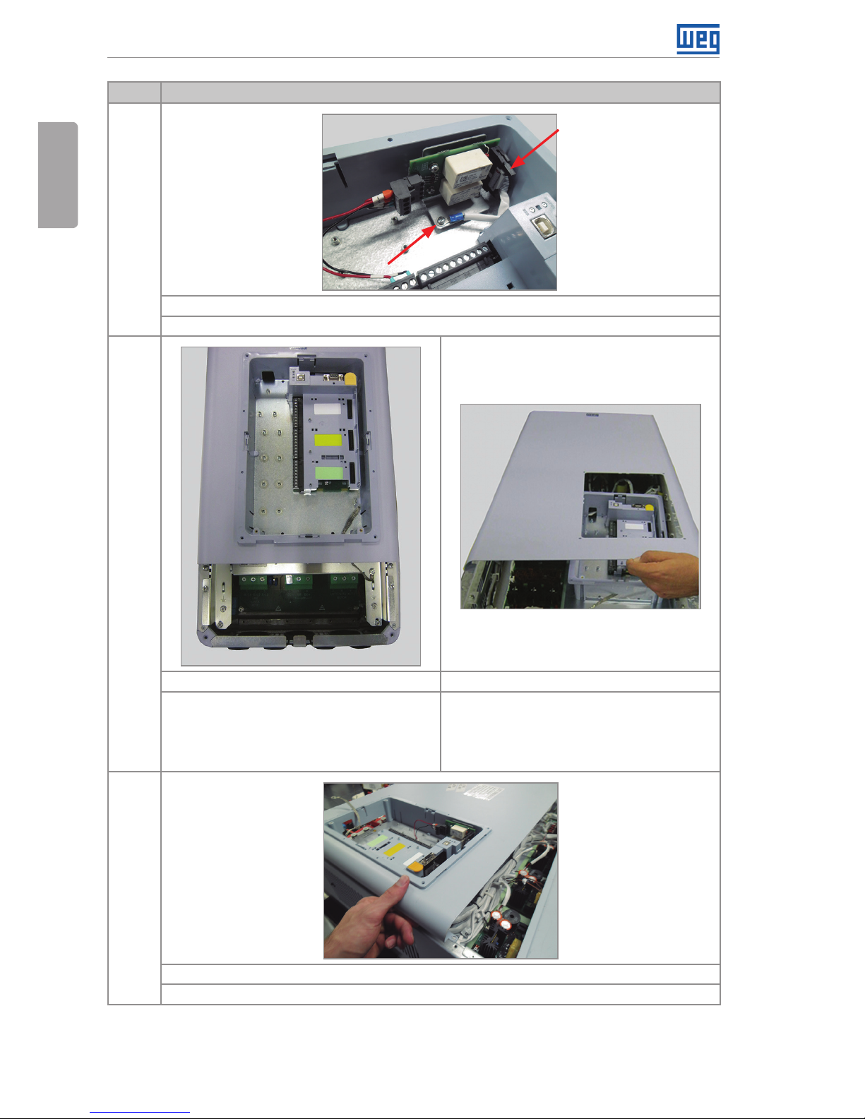
8
Only frame size H
Loosen the screw and the flat cable of the safety stop board as indicated.
9
Only frame size D Only frame sizes F and G
Loosen the two screws in the upper part
of the top front cover, then remove the two
screws in the lower part of the same cover.
Remove the upper front cover.
Loosen the two screws in the upper part
of the top front cover, then remove the two
screws in the lower part of the same cover.
Pass the control rack through the opening on
the top front cover and remove the cover.
10
Only frame size H
Loosen the four screws at the ends and remove the central cover.
Page 11

CFW-11/CFW70X | 11
External Power Supply for Control in 24 Vdc - KVDC-CFW11-2
English
Step Actions/Instructions
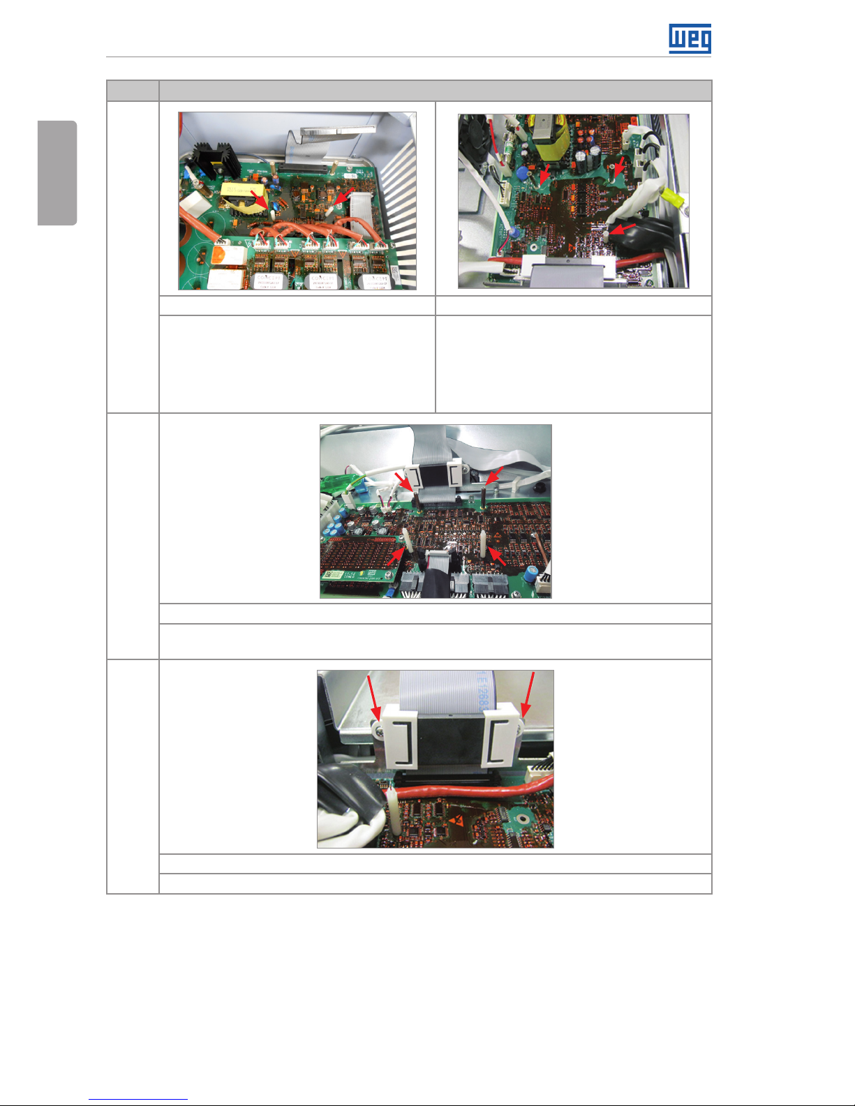
11
Only frame sizes F and G
Remove the ground cable from J7 connector on the power interface board (DFO2x).
12
Only frame sizes F and G Only frame size H
Remove the three ground screws from the
power interface board (DFO2x) as indicated.
Note: some inverters do not feature the
lower left ground point.
Remove the two ground screws from the
power interface board (IPHx) as indicated.
Page 12
12 | CFW-11/CFW70X
External Power Supply for Control in 24 Vdc - KVDC-CFW11-2
English
Step Actions/Instructions
13
Frame size D Frame sizes F and G
Fit the plastic spacer (c) as indicated.
Note: the metal spacers are assembled at
the factory.
Screw the metal spacers (b) where previously
the ground screws where located and fit the
plastic spacer (c) as indicated.
Note: some inverters do not feature the lower
left ground point; in this case, assemble only
two metal spacers.
14
Only frame size H
Screw the metal spacers (b) where the grounding screws were, and fit in the plastic spacers
(c) as indicated.
15
Frame sizes F, G and H
Remove the ferrite by loosening the two screws as indicated.
Page 13
CFW-11/CFW70X | 13
External Power Supply for Control in 24 Vdc - KVDC-CFW11-2
English
Step Actions/Instructions
16
Frame sizes F, G and H
Frame size F and G:
Remove the 160-mm ribbon-cable connected to connector XC60 of the power interface
board (DFO2x) and connect the 260-mm ribbon-cable (i) to this connector XC60. Fit the
ferrites on the ribbon-cable and tighten the two screws.
Frame size H:
Remove the 380-mm ribbon-cable connected to connector XC60 of the power interface
board (IPHx) and connect the 160-mm ribbon-cable (i) to this connector XC60. Fit the ferrites
on the ribbon-cable and tighten the two screws.
17
Only frame sizes F and G
Fold the ribbon-cable as indicated.
18
Frame sizes D and H Frame sizes F and G
Position and fit the insulation (d) on the spacers.
Page 14
14 | CFW-11/CFW70X
External Power Supply for Control in 24 Vdc - KVDC-CFW11-2
English
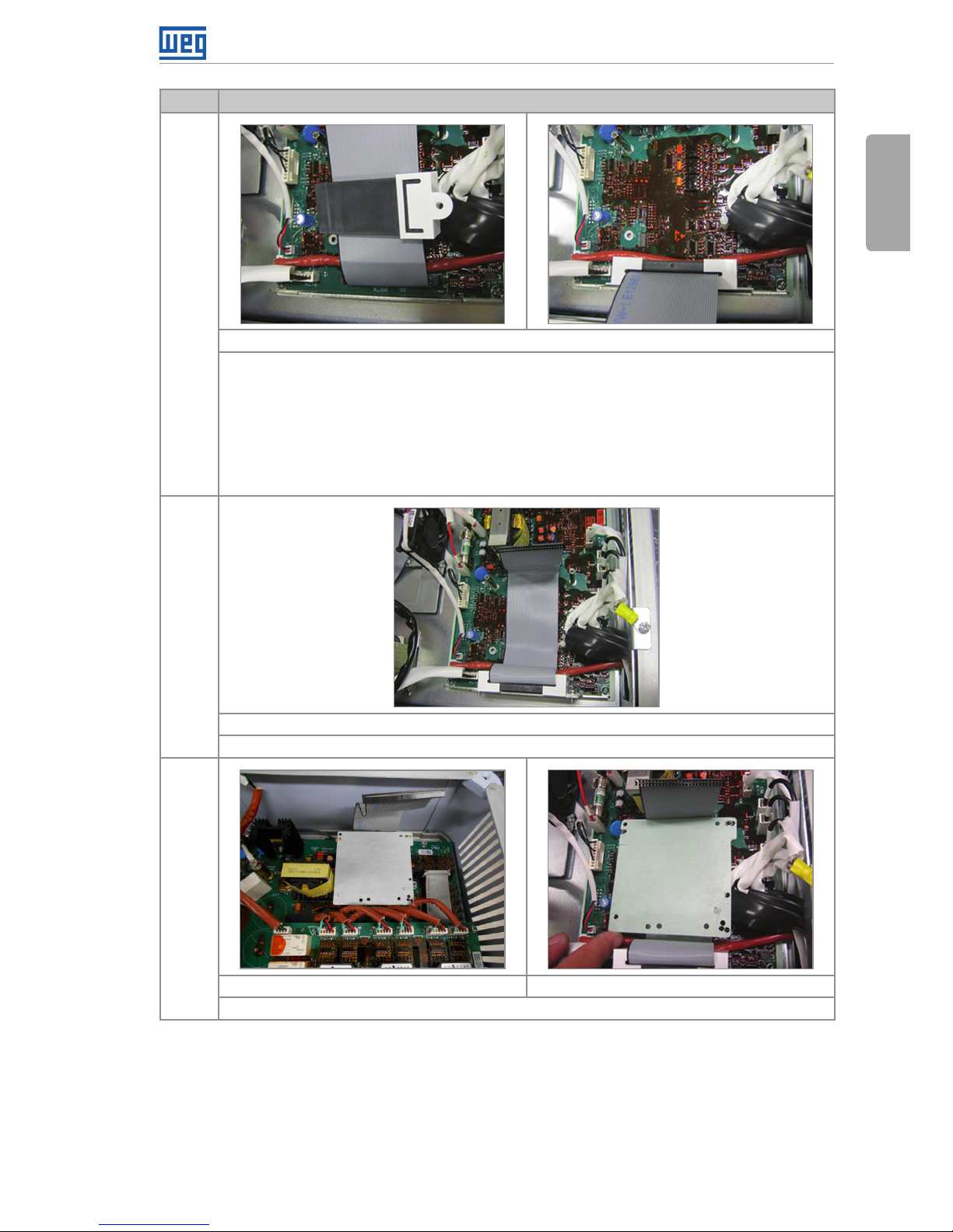
Step Actions/Instructions
19
Frame size D and H Frame sizes F and G
Fit the VDCx board (a) over the plastic spacer
and tighten the two screws (g) on the VDCx
board on the metal spacers.
Note: the inverters of frame size H have 2
plastic spacers.
Fit the VDCx board (a) over the plastic spacer
and tighten the three screws (g) on the VDCx
board on the metal spacers.
Note: if a metal spacer is not assembled,
one screw is not used.
20
Frame size D and H Frame sizes F and G
Fit the ribbon-cable to the XC60A connector (P11x/IPHx/DFO2x) of the VDCx board and fit
the plastic cover (f) on this connector.
Page 15
CFW-11/CFW70X | 15
External Power Supply for Control in 24 Vdc - KVDC-CFW11-2
English
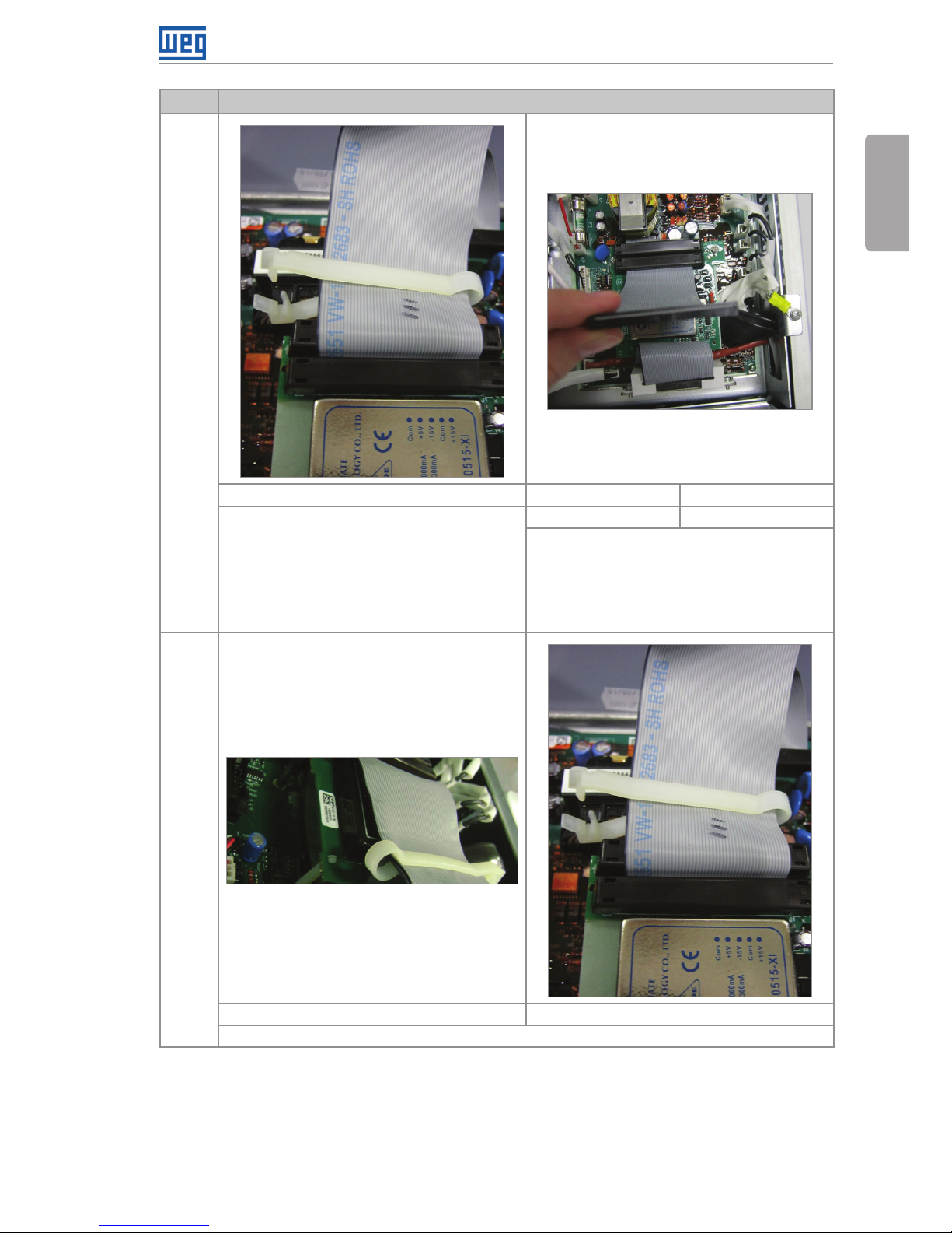
Step Actions/Instructions
21
Frame size D Frame size F Frame size G and H
- Connect the supplied 160-mm ribbon-
cable (h) to the XC60 connector (CC11x) and
snap the plastic cover on.
- Fasten the clamp, fixing the ribbon-cables
as indicated.
Make sure the position of the ribbon cable is
as shown in the figure.
Ribbon-cable 160 mm Ribbon-cable 533 mm (j)
Fit the ribbon-cable according to length and
indication above, and then fit the plastic cover
(f) on the connector, on the VDCx board.
Make sure the position of the ribbon cable is
as shown in the figure.
22
Frame sizes F and G Frame sizes D and H
Fasten the clamp (E), fixing the ribbon-cables as indicated.
Page 16
16 | CFW-11/CFW70X
External Power Supply for Control in 24 Vdc - KVDC-CFW11-2
English
Step Actions/Instructions
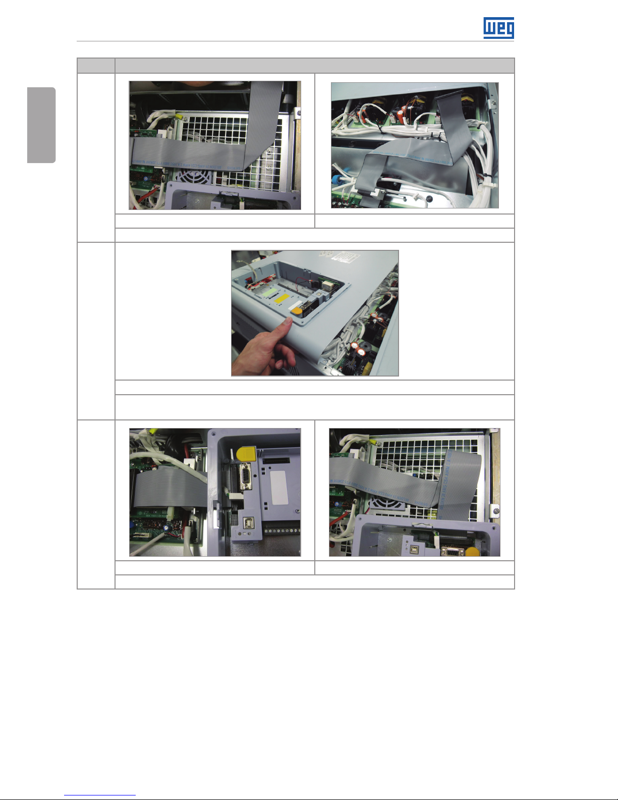
23
Frame size G Frame size H
Fold the ribbon-cable as indicated.
24
Only frame size H
Assemble the central cover, position the ground flexible cable in the lower right fastening
point, and fasten the four screws at the ends.
25
Only frame size F Frame sizes G and H
Fit the ribbon-cable and the plastic cover to the connector.
Page 17
CFW-11/CFW70X | 17
External Power Supply for Control in 24 Vdc - KVDC-CFW11-2
English
Step Actions/Instructions
26
Only frame sizes F and G
Fit the ground cable to J7 connector on the power interface board (DFO2x).
Note: check the connection of J7-XC98 cable, between the power interface board (DFO2x)
and the control board (CC11x).
27
Frame size D Frame sizes F and G
Assemble the upper front
cover.
Fit in the top front cover and pass the control rack through
the opening on the cover.
28
Only frame size H
Connect the flat cable and fasten the screw of the safety stop board as indicated.
Page 18

18 | CFW-11/CFW70X
External Power Supply for Control in 24 Vdc - KVDC-CFW11-2
English
Step Actions/Instructions
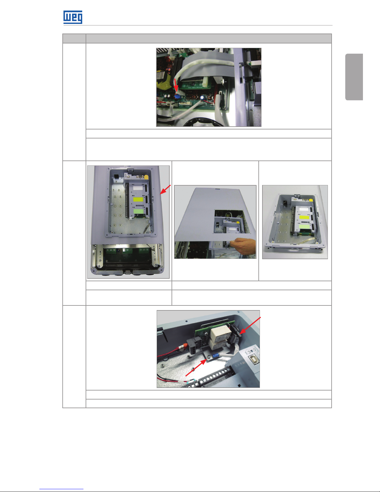
29
Only frame sizes D and H
Fit the ribbon-cable, the plastic cover on the
connector and ground cable to the XC98
connector of the vertical board of the control
board.
Fit the ground flexible braid on the lower
point on the screening plate of the control
board.
30
Only frame sizes F and G
Position the ground flexible braid in the lower right fixation point of the top front cover.
31
Frame size D Frame sizes F, G and H
Tighten the four screws of the top front cover.
Tighten the four screws of the top front cover
(the ground flexible braid must be fastened
together on the right side as shown in the
previous step).
Page 19

CFW-11/CFW70X | 19
External Power Supply for Control in 24 Vdc - KVDC-CFW11-2
English
Step Actions/Instructions
32
Only frame size H
Fit in the upper cover and fasten the two screws at the ends.
33
Frame sizes D, F, G and H
Fit in the lower cover and tighten the two screws at the ends of the lower front cover.
34
Frame sizes D, F, G and H
Fit in the front cover of the control rack, tighten the two screws and fit the HMI in.
Figure 2: Instructions to assemble the KVDC kit on the inverters with frame size D, F and G
Page 20

20 | CFW-11/CFW70X
External Power Supply for Control in 24 Vdc - KVDC-CFW11-2
English
4 LABEL
Put the two labels (k) supplied with the product after installing the kit on the inverter.
Those labels indicate that the inverter features the KVDC kit, which was not supplied from factory.
The labels must be put next to the product identification labels: one close to the big label, located
on the side of the inverter, and the other close to the label located under the HMI.
Side of the inverter Under the HMI
Figure 3: Suggested location to put up the labels supplied with the KVDC kit
5 CHECK AFTER INSTALLATION
After the installation of the kit in the inverter is concluded, power up the inverter and see if the
content on the parameter P0029 (Configuration of Power Hardware), on the bit 10 = 0.
For a description of the inverter operation with the KVDC kit refer to the user’s manual in the
chapter for optional items.
Page 21

Fuente de Alimentación Externa para Control en 24 Vdc - KVDC-CFW11-2
Español
CFW-11/CFW70X | 21
¡NOTA!
Esta guía contiene informaciones para la instalación del kit KVDC en el
convertidor CFW11 sin el sufijo W (CFW11) o W1 (CFW70X) en su designación.
El KVDC-CFW11-2 es un componente opcional del convertidor y, por lo tanto, no puede ser
vendido separadamente para usuarios finales o integradores.
Siempre debe ser instalado por la filial WEG o por el distribuidor WEG, en caso contrario, el
usuario final perderá la garantía por abrir las partes internas del convertidor.
1 CONVERTIDORES COMPATIBLES
Compatible con los siguientes modelos:
CFW-11 tamaño D 690 V.
CFW70X tamaño D 600 V.
CFW-11 tamaños F, G y H.
2 LISTA DE MATERIALES
(a) Placa Electrónica VDCx (b) Espaciadores Metálicos (c) Espaciadores Plásticos
(d) Aislamiento de la placa (e) Grapa para cable cinta
(f) Tapas plásticas para
conector del cable cinta
Page 22

Fuente de Alimentación Externa para Control en 24 Vdc - KVDC-CFW11-2
Español
22 | CFW-11/CFW70X
(g) Tornillo M3 (h) Cable cinta 160 mm (i) Cable cinta 260 mm
(j) Cable cinta 533 mm (k) Etiquetas
Figura 1: Contenido del kit KVDC-CFW11-2
Seleccione las piezas a ser montadas en el convertidor de acuerdo con la tabla 1; no hay
diferencias de acuerdo con los modelos.
Tabl a 1: Ítems a ser montados de acuerdo con el modelo del convertidor
Descripción
Cantidad por Modelo de Convertidor 1 (UN)
CFW-11/
CFW70X
CFW-11
Tamaño D Tamaño F Tamaño G Tamaño H
Placa Electrónica VDCx (a) 1 1 1 1
Espaciador metálico 28 mm (b) 2 3 3 2
Espaciador plástico 28 mm (c) 2 1 1 2
Aislamiento para la placa (d) 1 1 1 1
Grapa para cable cinta (e) 1 1 1 1
Tapa plástica para el conector
del cable cinta (f)
2 2 2 2
Tornillo M32 (g) 2 3 3 2
Cable cinta 160 mm (h) 1 - - 1
Cable cinta 260 mm (i) - 1 - -
Cable cinta 533 mm (j) - - 1 1
Etiqueta (k) 2 2 2 2
Notas:
1 Para informaciones sobre el tamaño del convertidor, verifique la tabla de especificación técnica (tabla 8.1 en el manual del usuario del
CFW-11 y tablas B.1 y B.2 en el manual del usuario del CFW700 / CFW701).
2 En caso de que la sustitución del tornillo existente sea necesaria.
Page 23

Fuente de Alimentación Externa para Control en 24 Vdc - KVDC-CFW11-2
Español
CFW-11/CFW70X | 23
3 PROCEDIMIENTOS PARA INSTALAR EL KIT EN EL CONVERTIDOR
3.1 TAMAÑOS D, F, G Y H
Paso Acciones/Instrucciones
1
Tamaños D, F, G y H
Remueva la HMI.
2
Tamaños D, F, G y H
Suelte los dos tornillos en la tapa frontal del control y remuévalos.
Page 24

Fuente de Alimentación Externa para Control en 24 Vdc - KVDC-CFW11-2
Español
24 | CFW-11/CFW70X
Paso Acciones/Instrucciones
3
Tamaños D, F, G y H
Retire los dos tornillos en las extremidades de la tapa frontal inferior y remuévala.
4
Solamente tamaño H
Retire los dos tornillos en las extremidades de la tapa superior y remuévala.
5
Tamaños F y G
Remueva la tapa plástica en el conector y el cable cinta.
Tenga cuidado de no dañar los componentes en la placa próxima del conector.
Page 25

Fuente de Alimentación Externa para Control en 24 Vdc - KVDC-CFW11-2
Español
CFW-11/CFW70X | 25
Paso Acciones/Instrucciones
6
Solamente tamaños D y H
Suelte el cable flexible de puesta a tierra en la chapa de blindaje.
7
Solamente tamaños D y H Solamente tamaños F y G
Remueva el cable de puesta a tierra de XC98
de la placa vertical de la placa de control, la
tapa plástica en el conector y el cable cinta.
Tenga cuidado de no dañar los componentes
en la placa próxima al conector.
Nota: este cable fue adicionado durante la
certificación CE. Algunos accionamientos no
lo poseen.
Usando un destornillador, suelte el rack de
control, liberando las cuatro trabas.
Page 26

Fuente de Alimentación Externa para Control en 24 Vdc - KVDC-CFW11-2
Español
26 | CFW-11/CFW70X
Paso Acciones/Instrucciones
8
Solamente tamaño H
Retire el tornillo y el cable flat de la tarjeta de parada de seguridad conforme es indicado.
9
Solamente tamaño D Solamente tamaños F y G
Suelte los dos tornillos de la parte superior
de la tapa frontal superior y remueva los dos
tornillos de la parte inferior de la misma tapa.
Remueva la tapa frontal superior.
Suelte los dos tornillos de la parte superior
de la tapa frontal superior y remueva los dos
tornillos de la parte inferior de la misma tapa.
Pase el rack de control a través de la
abertura de la tapa frontal superior y
remueva la tapa.
10
Solamente tamaño H
Retire los cuatro tornillos de las extremidades y remueva la tapa central.
Page 27

Fuente de Alimentación Externa para Control en 24 Vdc - KVDC-CFW11-2
Español
CFW-11/CFW70X | 27
Paso Acciones/Instrucciones
11
Solamente tamaños F y G
Remueva el cable tierra del conector J7 en la placa de interfaz de potencia (DFO2x).
12
Solamente tamaños F y G Solamente tamaño H
Remueva los tres tornillos de puesta a tierra
de la placa de interfaz de potencia (DFO2x)
conforme es indicado.
Nota: algunos convertidores no poseen el
punto de puesta a tierra inferior izquierdo.
Remueva los dos tornillos de puesta a tierra
de la placa de interfaz de potencia (IPHx)
conforme es indicado.
Page 28

Fuente de Alimentación Externa para Control en 24 Vdc - KVDC-CFW11-2
Español
28 | CFW-11/CFW70X
Paso Acciones/Instrucciones
13
Tama ño D Tamaños F y G
Encaje el espaciador plástico (c) como es
indicado.
Nota: los espaciadores metálicos son
montados en fábrica.
Atornille los espaciadores metálicos (b)
donde anteriormente estaban los tornillos
de puesta a tierra y encaje el espaciador
plástico (c) como es indicado.
Nota: algunos convertidores no poseen el
punto de puesta a tierra inferior izquierdo;
en este caso, monte solamente dos
espaciadores metálicos.
14
Solamente tamaño H
Atornille los espaciadores metálicos (b) donde anteriormente estaban los tornillos de puesta a
tierra y encaje los espaciadores plásticos (c) como es indicado.
15
Tamaños F, G y H
Remueva la ferrita aflojando los dos tornillos como es indicado.
Page 29

Fuente de Alimentación Externa para Control en 24 Vdc - KVDC-CFW11-2
Español
CFW-11/CFW70X | 29
Paso Acciones/Instrucciones
16
Tamaños F, G y H
Tamaño F y G:
Remueva el cable cinta de 160 mm conectado al conector XC60 de la placa de interfaz de
potencia (DFO2x) y conecte el cable cinta de 260 mm (i) al conector XC60. Encaje las ferritas
en el cable cinta y apriete los dos tornillos.
Tamaño H:
Remueva el cable cinta de 380 mm conectado al conector XC60 de la placa de interfaz de
potencia (IPHx) y conecte el cable cinta de 160 mm (i) al conector XC60. Encaje las ferritas en
el cable cinta y apriete los dos tornillos.
17
Solamente tamaños F y G
Doble el cable cinta como es indicado.
18
Tamaños D y H Tamaños F y G
Posicione y encaje el aislamiento (d) en los espaciadores.
Page 30

Fuente de Alimentación Externa para Control en 24 Vdc - KVDC-CFW11-2
Español
30 | CFW-11/CFW70X
Paso Acciones/Instrucciones
19
Tamaños D y E Tamaños F y G
Encaje la placa VDCx (a) sobre el espaciador
plástico y apriete los dos tornillos (g) en la
placa VDCx de los espaciadores metálicos.
Nota: los convertidores del tamaño H tiene 2
espaciadores de plástico.
Encaje la placa VDCx (a) sobre el espaciador
plástico y apriete los tres tornillos (g) en la
placa VDCx, en los espaciadores metálicos.
Nota: si un espaciador metálico no estuviera
montado, no será usado un tornillo.
20
Tamaños D y E Tamaños F y G
Encaje el cable cinta en el conector XC60A (P11x/IPHx/DFO2x) de la placa VDCx y encaje la
tapa plástica (f) en este conector.
Page 31

Fuente de Alimentación Externa para Control en 24 Vdc - KVDC-CFW11-2
Español
CFW-11/CFW70X | 31
Paso Acciones/Instrucciones
21
Tama ño D Tama ño F Tamaños G y H
- Conecte el cable cinta de 160 mm
suministrado (h) al conector XC60 (CC11x) y
monte la tapa plástica.
- Sujete la grapa, fijando los cables cinta
como es indicado.
Asegúrese de que el cable cinta quede
posicionado como en la figura.
Cable cinta 160 mm Cable cinta 533 mm (j)
Encaje el cable cinta de acuerdo con la
longitud y la indicación de arriba, luego
encaje la tapa plástica (f) en el conector, en
la placa VDCx.
Asegúrese de que el cable cinta quede
posicionado como en la figura.
22
Tamaños F y G Tamaños D y H
Sujete la grapa (e), fijando los cables cinta como es indicado.
Page 32

Fuente de Alimentación Externa para Control en 24 Vdc - KVDC-CFW11-2
Español
32 | CFW-11/CFW70X
Paso Acciones/Instrucciones
23
Tamaño G Tamaño H
Doble el cable cinta como es indicado.
24
Solamente tamaño H
Monte la tapa central, posicione el cable flexible de puesta a tierra en el punto de fijación
inferior derecho de la tapa y apriete los cuatro tornillos de las extremidades.
25
Solamente tamaño F Tamaños G y H
Encaje el cable cinta y la tapa plástica en el conector.
Page 33

Fuente de Alimentación Externa para Control en 24 Vdc - KVDC-CFW11-2
Español
CFW-11/CFW70X | 33
Paso Acciones/Instrucciones
26
Solamente tamaños F y G
Encaje el cable de puesta a tierra en el conector J7 de la placa de interfaz de potencia (DFO2x).
Nota: verifique la conexión del cable J7-XC98, entre la placa de interfaz de potencia (DFO2x)
y a placa de controle (CC11x).
27
Tama ño D Tamaños F y G
Monte la tapa frontal superior.
Monte la tapa frontal superior y pase el rack de control a
través de la abertura de la tapa.
28
Solamente tamaño H
Conecte el cable flat y apriete el tornillo de la tarjeta de parada de seguridad conforme es
indicado.
Page 34

Fuente de Alimentación Externa para Control en 24 Vdc - KVDC-CFW11-2
Español
34 | CFW-11/CFW70X
Paso Acciones/Instrucciones
29
Solamente tamaños D y H
Encaje el cable cinta, la tapa plástica en el
conector y el cable de puesta a tierra en el
conector XC98 en la placa vertical de la placa
de control.
Monte el cable flexible de puesta a tierra en
el punto más bajo de la chapa de blindaje de
la placa de control.
30
Solamente tamaños F y G
Posicione el cable flexible de puesta a tierra en el punto de fijación inferior derecho de la tapa
frontal superior.
31
Tama ño D Tamaños F, G y H
Apriete los cuatro tornillos de la tapa frontal
superior.
Apriete los cuatro tornillos de la tapa frontal
superior (el cable flexible de puesta a tierra
debe ser sujetado también en el lado derecho,
como es mostrado en el paso anterior).
Page 35

Fuente de Alimentación Externa para Control en 24 Vdc - KVDC-CFW11-2
Español
CFW-11/CFW70X | 35
Paso Acciones/Instrucciones
32
Solamente tamaño H
Encaje la tapa superior y apriete los dos tornillos en las extremidades.
33
Tamaños F, G y H
Encaje la tapa inferior y apriete los dos tornillos en sus extremidades.
34
Tamaños D, F, G y H
Encaje la tapa frontal del rack de control, apriete los dos tornillos y monte la IHM.
Figura 2: Instrucciones para montar el kit KVDC en los convertidores con Tamaños D, F y G
Page 36

Fuente de Alimentación Externa para Control en 24 Vdc - KVDC-CFW11-2
Español
36 | CFW-11/CFW70X
4 ETIQUETA
Coloque las dos etiquetas (k) suministradas con el producto luego de instalar el kit en el convertidor.
Estas etiquetas indican que el convertidor posee kit KVDC, que no fue suministrado de fábrica.
Las etiquetas deben ser colocadas al lado de las etiquetas de identificación del producto: una
cerca de la etiqueta grande, localizada en la lateral del convertidor, y la otra cerca de la etiqueta
localizada en la parte inferior de la IHM.
Lateral del convertidor Parte inferior de la IHM
Figura 3: Localización sugerida para colocar las etiquetas suministradas con el kit KVDC
5 INSPECCIÓN TRAS LA INSTALACIÓN
Luego de que la instalación del kit en el convertidor sea concluida, energice el convertidor y vea
si el contenido del parámetro P0029 (Configuración del Equipo de Potencia), en el bit 10 = 0.
Para una descripción de la operación del convertidor con el kit KVDC, consulte el manual del
usuario en el capítulo para ítems opcionales.
Page 37

Fonte de Alimentação Externa para Controle em 24 Vdc - KVDC-CFW11-2
Português
CFW-11/CFW70X | 37
NOTA!
Este guia contém informações para a instalação do kit KVDC no inversor sem
o sufixo W (CFW11) ou W1 (CFW70X) na sua descrição.
O KVDC-CFW11-2 é um componente opcional do inversor e, portanto, não pode ser vendido
separadamente para usuários finais ou integradores.
Ele deve sempre ser instalado pela filial WEG ou distribuidor WEG, caso contrário, o usuário
final perderá a garantia por abrir as partes internas do inversor.
1 INVERSORES COMPATÍVEIS
Compatível com os seguintes modelos:
CFW-11 mecânica D 690 V.
CFW70X mecânica D 600 V.
CFW-11 mecânicas F, G e H.
2 LISTA DE MATERIAIS
(a) Placa Eletrônica VDCx (b) Espaçadores Metálicos (c) Espaçadores Plásticos
(d) Isolamento da placa (e) Grampo para cabo fita
(f) Tampas plásticas para
conector do cabo fita
Page 38

Fonte de Alimentação Externa para Controle em 24 Vdc - KVDC-CFW11-2
Português
38 | CFW-11/CFW70X
(g) Parafuso M3 (h) Cabo fita 160 mm (i) Cabo fita 260 mm
(j) Cabo fita 533 mm (k) Etiquetas
Figura 1: Conteúdo do kit KVDC-CFW11-2
Selecione as peças a serem montadas no inversor de acordo com a tabela 1; não há diferenças
de acordo com os modelos.
Tabela 1: Itens a serem montados de acordo com o modelo do inversor
Descrição
Quantidade por Modelo de Inversor1 (UN)
CFW-11/
CFW70X
CFW-11
Mecânica D Mecânica F Mecânica G Mecânica H
Placa Eletrônica VDCx (a) 1 1 1 1
Espaçador metálico 28 mm (b) 2 3 3 2
Espaçador plástico 28 mm (c) 2 1 1 2
Isolamento para a placa (d) 1 1 1 1
Grampo para cabo fita (e) 1 1 1 1
Tampa plástica para o conector
do cabo fita (f)
2 2 2 2
Parafuso M32 (g) 2 3 3 2
Cabo fita 160 mm (h) 1 - - 1
Cabo fita 260 mm (i) - 1 - -
Cabo fita 533 mm (j) - - 1 1
Etiqueta (k) 2 2 2 2
Notas:
1 Para infor mações sobre a mecânica do inversor, verifique a tabela de especificação técnica (tabela 8.1 no manual do usuário do CFW-11
e tabelas B.1 e B.2 no manual do usuário do CFW700 / CFW701).
2 No caso da substituição do parafuso existente ser neces sária.
Page 39

Fonte de Alimentação Externa para Controle em 24 Vdc - KVDC-CFW11-2
Português
CFW-11/CFW70X | 39
3 PROCEDIMENTOS PARA INSTALAR O KIT NO INVERSOR
3.1 MECÂNICAS D, F, G E H
Passo Ações/Instruções
1
Mecânicas D, F, G e H
Remova a HMI.
2
Mecânicas D, F, G e H
Solte os dois parafusos na tampa frontal do controle e os remova.
Page 40

Fonte de Alimentação Externa para Controle em 24 Vdc - KVDC-CFW11-2
Português
40 | CFW-11/CFW70X
Passo Ações/Instruções
3
Mecânicas D, F, G e H
Remova os dois parafusos nas extremidades da tampa frontal inferior e a remova.
4
Somente mecânica H
Remova os dois parafusos nas extremidades da tampa superior e a remova.
5
Mecânicas F e G
Remova a tampa plástica no conector e o cabo fita.
Tenha cuidado para não danificar os componentes na placa próxima do conector.
Page 41

Fonte de Alimentação Externa para Controle em 24 Vdc - KVDC-CFW11-2
Português
CFW-11/CFW70X | 41
Passo Ações/Instruções
6
Somente mecânicas D e H
Solte o cabo flexível de aterramento na chapa de blindagem.
7
Somente mecânicas D e H Somente mecânicas F e G
Remova o cabo de aterramento de XC98 da
placa vertical da placa de controle, a tampa
plástica no conector e o cabo fita.
Tenha cuidado para não danificar os
componentes na placa próxima do conector.
Nota: este cabo foi adicionado durante a
certificação CE. Alguns acionamentos não
possuem este cabo.
Usando uma chave de fenda, solte o rack de
controle, liberando as quatro travas.
Page 42

Fonte de Alimentação Externa para Controle em 24 Vdc - KVDC-CFW11-2
Português
42 | CFW-11/CFW70X
Passo Ações/Instruções
8
Somente mecânica H
Solte o parafuso e o cabo flat do cartão de parada de segurança conforme indicado.
9
Somente mecânica D Somente mecânicas F e G
Solte os dois parafusos na parte superior da
tampa frontal superior e então remova os
dois parafusos na parte inferior da mesma
tampa. Remova a tampa frontal superior.
Solte os dois parafusos na parte superior da
tampa frontal superior e então remova os dois
parafusos na parte inferior da mesma tampa.
Passe o rack de controle através da abertura
na tampa frontal superior e remova a tampa.
10
Somente mecânica H
Solte os quatro parafusos das extremidades e remova a tampa central.
Page 43

Fonte de Alimentação Externa para Controle em 24 Vdc - KVDC-CFW11-2
Português
CFW-11/CFW70X | 43
Passo Ações/Instruções
11
Somente mecânicas F e G
Remova o cabo terra do conector J7 na placa de interface de potência (DFO2x).
12
Somente mecânicas F e G Somente mecânica H
Remova os três parafusos de aterramento
da placa de interface de potência (DFO2x)
conforme indicado.
Nota: Alguns inversores não possuem o
ponto de aterramentos inferior esquerdo.
Remova os dois parafusos de aterramento
da placa de interface de potência (IPHx)
conforme indicado.
Page 44

Fonte de Alimentação Externa para Controle em 24 Vdc - KVDC-CFW11-2
Português
44 | CFW-11/CFW70X
Passo Ações/Instruções
13
Mecânica D Mecânicas F e G
Encaixe o espaçador plástico (c) como indicado.
Nota: espaçadores metálicos são montados
na fábrica.
Parafuse os espaçadores metálicos (b) onde
anteriormente estavam os parafusos de
aterramento e encaixe o espaçador plástico
(c) como indicado.
Nota: alguns inversores não possuem o ponto
de aterramento inferior esquerdo; neste caso,
monte somente dois espaçadores metálicos.
14
Somente mecânica H
Parafuse os espaçadores metálicos (b) onde anteriormente estavam os parafusos de
aterramento e encaixe os espaçadores plásticos (c) como indicado.
15
Mecânicas F, G e H
Remova a ferrite afrouxando os dois parafusos como indicado.
Page 45

Fonte de Alimentação Externa para Controle em 24 Vdc - KVDC-CFW11-2
Português
CFW-11/CFW70X | 45
Passo Ações/Instruções
16
Mecânicas F, G e H
Mecânica F e G:
Remova o cabo fita de 160 mm conectado ao conector XC60 da placa de interface de
potência (DFO2x) e conecte o cabo fita de 260 mm (i) ao conector XC60. Encaixe as ferrites
no cabo fita e aperte os dois parafusos.
Mecânica H:
Remova o cabo fita de 380 mm conectado ao conector XC60 da placa de interface de
potência (IPHx) e conecte o cabo fita de 160 mm (i) ao conector XC60. Encaixe as ferrites no
cabo fita e aperte os dois parafusos.
17
Somente mecânicas F e G
Dobre o cabo fita como indicado.
18
Mecânicas D e H Mecânicas F e G
Posicione e encaixe o isolamento (d) nos espaçadores.
Page 46

Fonte de Alimentação Externa para Controle em 24 Vdc - KVDC-CFW11-2
Português
46 | CFW-11/CFW70X
Passo Ações/Instruções
19
Mecânicas D e H Mecânicas F e G
Encaixe a placa VDCx (a) sobre o espaçador
plástico e aperte os dois parafusos (g) na
placa VDCx nos espaçadores metálicos.
Nota: os inversores da mecânica H
possuem 2 espaçadores plásticos.
Encaixe a placa VDCx (a) sobre o espaçador
plástico e aperte os três parafusos (g) na
placa VDCx nos espaçadores metálicos.
Nota: se um espaçador metálico não estiver
montado, um parafuso não é usado.
20
Mecânicas D e H Mecânicas F e G
Encaixe o cabo fita no conector XC60A (P11x/IPHx/DFO2x) da placa VDCx e encaixe a tampa
plástica (f) neste conector.
Page 47

Fonte de Alimentação Externa para Controle em 24 Vdc - KVDC-CFW11-2
Português
CFW-11/CFW70X | 47
Passo Ações/Instruções
21
Mecânica D Mecânica F Mecânicas G e H
- Conecte o cabo fita de 160 mm fornecido
(h) ao conector XC60 (CC11x) e monte a
tampa plástica.
- Prenda o grampo, fixando os cabos fita
como indicado.
Certifique-se de que o cabo fita fique
posicionado como na figura.
Cabo fita 160 mm Cabo fita 533 mm (j)
Encaixe o cabo fita de acordo com o
comprimento e indicação acima e então
encaixe a tampa plástica (f) no conector, na
placa VDCx.
Certifique-se de que o cabo fita fique
posicionado como na figura.
22
Mecânicas F e G Mecânicas D e H
Prenda o grampo (e), fixando os cabos fita como indicado.
Page 48

Fonte de Alimentação Externa para Controle em 24 Vdc - KVDC-CFW11-2
Português
48 | CFW-11/CFW70X
Passo Ações/Instruções
23
Mecânica G Mecânica H
Dobre o cabo fita como indicado.
24
Somente mecânica H
Monte a tampa central, posicione o cabo flexível de aterramento no ponto de fixação inferior
direito da tampa e aperte os quatro parafusos das extremidades.
25
Somente mecânica F Mecânicas G e H
Encaixe o cabo fita e a tampa plástica no conector.
Page 49

Fonte de Alimentação Externa para Controle em 24 Vdc - KVDC-CFW11-2
Português
CFW-11/CFW70X | 49
Passo Ações/Instruções
26
Somente mecânicas F e G
Encaixe o cabo de aterramento no conector J7 na placa de interface de potência (DFO2x).
Nota: verifique a conexão do cabo J7-XC98, entre a placa de interface de potência (DFO2x) e
a placa de controle (CC11x).
27
Mecânica D Mecânicas F e G
Monte a tampa frontal
superior.
Monte a tampa frontal superior e passe o rack de controle
através da abertura na tampa.
28
Somente mecânica H
Conecte o cabo flat e aperte o parafuso do cartão de parada de segurança conforme
indicado.
Page 50

Fonte de Alimentação Externa para Controle em 24 Vdc - KVDC-CFW11-2
Português
50 | CFW-11/CFW70X
Passo Ações/Instruções
29
Somente mecânicas D e H
Encaixe o cabo fita, a tampa plástica no
conector e cabo de aterramento no conector
XC98 da placa vertical da placa de controle.
Monte o cabo flexível de aterramento no
ponto mais baixo na chapa de blindagem da
placa de controle.
30
Somente mecânicas F e G
Posicione o cabo flexível de aterramento no ponto de fixação inferior direito da tampa frontal
superior.
31
Mecânica D Mecânicas F, G e H
Aperte os quatro parafusos da tampa frontal
superior.
Aperte os quatro parafusos da tampa frontal
superior (o cabo flexível de aterramento deve
ser preso junto no lado direito como mostrado
no passo anterior).
Page 51

Fonte de Alimentação Externa para Controle em 24 Vdc - KVDC-CFW11-2
Português
CFW-11/CFW70X | 51
Passo Ações/Instruções
32
Somente mecânica H
Encaixe a tampa superior e aperte os dois parafusos nas extremidades.
33
Mecânicas D, F, G e H
Encaixe a tampa inferior e aperte os dois parafusos em suas extremidades.
34
Mecânicas D, F, G e H
Encaixe a tampa frontal do rack de controle, aperte dos dois parafusos e monte a IHM.
Figura 2: Instruções para montar o kit KVDC nos inversores com mecânicas D, F, G e H
Page 52

Fonte de Alimentação Externa para Controle em 24 Vdc - KVDC-CFW11-2
Português
52 | CFW-11/CFW70X
4 ETIQUETA
Coloque as duas etiquetas (K) fornecidas com o produto após instalar o kit no inversor.
Estas etiquetas indicam que o inversor possui o kit KVDC, que não foi fornecido de fábrica.
As etiquetas devem ser colocadas ao lado das etiquetas de identificação do produto: uma
perto da etiqueta grande, localizada na lateral do inversor, e a outra perto da etiqueta localizada
sob a IHM.
Lateral do inversor Parte inferior da IHM
Figura 3: Localização sugerida para colocar as etiquetas fornecidas com o kit KVDC
5 INSPEÇÃO APÓS A INSTALAÇÃO
Após a instalação do kit no inversor ser concluída, energize o inversor e veja se o conteúdo do
parâmetro P0029 (Configuração de Equipamento de Potência), no bit 10 = 0.
Para uma descrição da operação do inversor com o kit KVDC, consulte o manual do usuário
no capítulo para itens opcionais.
Page 53

NOTES / NOTAS / ANOTAÇÕES
Page 54

NOTES / NOTAS / ANOTAÇÕES
Page 55

Page 56

Document: 10001993767 / 02
WEG Drives & Controls - Automação LTDA.
Jaraguá do Sul - SC - Brazil
Phone 55 (47) 3276-4000 - Fax 55 (47) 3276-4020
São Paulo - SP - Brazil
Phone 55 (11) 5053-2300 - Fax 55 (11) 5052-4212
automacao@weg.net
www.weg.net
12213288
 Loading...