

Page 1
Motors | Automation | Energy | Transmission & Distribution | Coatings
Frequency Inverter
Convertidor de Frecuencia
Inversor de Frequência
CFW700
User's Manual
Manual del Usuario
Manual do Usuário
Language: English, Spanish, Portuguese
Page 2

User's Manual
Series: CFW700
Language: English
Document: 10000771684 / 04
Models: Frame Sizes A...E
Date: 05/2015
Page 3

Summary of Revisions
The table below describes the revisions made to this manual.
Version Review Description
- R01 First edition
- R02 Cover update
- R03 General revision
- R04
Inclus ion of n ew fr ame s izes m ode ls D an d E
Update from IP54 to IP55 in frame sizes B and C
ATTENTION!
Parameters P0296 (Rated Line Voltage), P0400 (Rated Motor Voltage) and
P0403 (Rated Motor Frequency), were readjusted at the:
200...240 V / 220 / 230 V (S2, B2 and T2) models: P0296 = 0 (200 / 240 V),
P0400 = 220 V and P0403 = 60 Hz.
380...480 V (T4) models: P0296 = 3 (440 / 460 V), P0400 = 440 V and
P0403 = 60 Hz.
500...600 V (T5) models: P0296 = 6 (550 / 575 V), P0400 = 575 V and P0403
= 60 Hz.
For different values of line rated voltage and/or motor voltage and frequency,
set these parameters through the STARTUP menu, as presented in the user's
manual section 5.2 START-UP on page 48.
Page 4

Contents
1 SAFETY INSTRUCTIONS .................................................................... 1
1.1 SAFETY WARNINGS IN THE MANUAL .................................................... 1
1.2 SAFETY WARNINGS IN THE PRODUCT ................................................. 1
1.3 PRELIMINARY RECOMMENDATIONS ....................................................2
2 GENERAL INSTRUCTIONS ................................................................3
2.1 ABOUT THE MANUAL .............................................................................. 3
2.2 ABOUT THE CFW700 ................................................................................ 3
2.3 IDENTIFICATION .......................................................................................6
2.4 LIST OF AVAILABLE MODELS ................................................................ 8
2.5 IDENTIFICATION LABELS ........................................................................ 8
2.6 RECEIVING AND STORAGE .....................................................................9
3 INSTALLATION AND CONNECTION ................................................10
3.1 MECHANICAL INSTALLATION ...............................................................10
3.1.1 Installation Environment ...............................................................10
3.1.2 Mounting Considerations .............................................................10
3.2 ELECTRICAL INSTALLATION ................................................................11
3.2.1 Identification of the Power and Grounding Terminals ..............12
3.2.2 Power / Grounding Wiring and Fuses ......................................... 14
3.2.3 Power Connections .......................................................................15
3.2.3.1 Input Connections .............................................................15
3.2.3.2 Dynamic Braking (standard built-in for frame
sizes A, B, C and D and optional built-in for frame size
E - CFW700...DB...) ........................................................................16
3.2.3.3 Output Connections ......................................................... 17
3.2.4 Grounding Connections ...............................................................19
3.2.5 Control Connections ....................................................................19
3.2.6 Cable Distances ............................................................................23
3.3 INSTALLATION ACCORDING TO THE EUROPEAN DIRECTIVE
OF ELECTROMAGNETIC COMPATIBILITY ................................................24
3.3.1 Conformal Installation ..................................................................24
3.3.2 Emission and Immunity Levels ....................................................25
English
4 KEYPAD (HMI) AND BASIC PROGRAMMING ...............................26
4.1 INTEGRAL KEYPAD - HMI-CFW700 ......................................................26
4.2 APPLICATIONS ........................................................................................29
4.2.1 PID Regulator Application ............................................................29
4.2.1.1 Academic PID ..................................................................... 33
4.2.2 Electronic Potentiometer (EP) Application ...............................38
4.2.3 Multispeed Application ...............................................................40
4.2.4 3-Wire Start/Stop Command Application ..................................44
4.2.5 Forward/Reverse Run Application..............................................45
5 FIRST TIME POWER-UP AND START-UP .......................................48
5.1 PREPARE FOR START-UP ......................................................................48
5.2 START-UP.................................................................................................48
5.2.1 Oriented Start-up Menu ................................................................49
5.2.2 Basic Application Menu ..............................................................51
Page 5

Contents
6 TROUBLESHOOTING AND MAINTENANCE ...................................52
6.1 FAULTS AND ALARMS ............................................................................52
English
6.2 SOLUTIONS FOR THE MOST FREQUENT PROBLEMS ......................52
6.3 INFORMATION FOR CONTACTING TECHNICAL SUPPORT ..............53
6.4 PREVENTIVE MAINTENANCE................................................................53
6.5 CLEANING INSTRUCTIONS ..................................................................55
7 OPTION KITS AND ACCESSORIES ................................................. 57
7.1 OPTION KITS ............................................................................................ 57
7.1.1 Built-in RFI Filter (only for frame sizes A, B, C and D) -
CFW700...C3... ......................................................................................... 57
7.1.2 Dynamic Braking IGBT (only for frame size E in 220 / 230 V
and 380…480 V models and for frame sizes D and E in 500…600 V
models) - CFW700...DB... ...................................................................... 57
7.1.3 Nema1 Protection Degree (only for frame sizes A, B, C and E) -
CFW700...N1... .........................................................................................57
7.1.4 IP55 Protection Degree (only for frame sizes B and C) -
CFW700...N12... .......................................................................................57
7.1.5 IP21 Protection Degree (only for frame sizes A, B and C) -
CFW700...21... ..........................................................................................57
7.1.6 STO Function - CFW700...Y1... ......................................................57
7.1.7 24 Vdc External Control Power Supply - CFW700...W1... ..........58
7.2 ACCESSORIES .........................................................................................58
8 TECHNICAL SPECIFICATIONS ........................................................60
8.1 POWER DATA ...........................................................................................60
8.2 ELECTRICAL/GENERAL SPECIFICATIONS .........................................61
8.2.1 Codes and Standards ...................................................................63
APPENDIX A - DIAGRAMS AND FIGURES ......................................201
APPENDIX B - TECHNICAL SPECIFICATIONS ................................212
Page 6
Safety Instructions
1 SAFETY INSTRUCTIONS
This manual provides information for the proper installation and operation of the CFW700
frequency inverter.
Only trained personnel, with proper qualifications, and familiar with this kind of equipment
and associated machinery shall plan and implement the installation, starting, operation, and
maintenance of this equipment. The personnel shall follow all the safety instructions described in
this manual and/or defined by the local regulations. Failure to comply with the safety instructions
may result in death, serious injury, and equipment damage.
1.1 SAFETY WARNINGS IN THE MANUAL
DANGER!
The procedures recommended in this warning have the purpose of protecting
the user against death, serious injuries and considerable material damage.
ATTENTION!
The procedures recommended in this warning have the purpose of avoiding
material damage.
NOTE!
The text intents to supply important information for the correct understanding
and good operation of the product.
English
1.2 SAFETY WARNINGS IN THE PRODUCT
The following symbols are attached to the product, serving as safety notices:
High voltages are present.
Components sensitive to electrostatic discharge.
Do not touch them.
Mandatory connection to the protective ground (PE).
Connection of the shield to the ground.
Hot surface.
CFW700 | 1
Page 7
Safety Instructions
1.3 PRELIMINARY RECOMMENDATIONS
English
DANGER!
Always disconnect the main power supply before touching any electrical
device associated with the inverter. Several components may remain charged
with high voltage and/or in movement (fans), even after the AC power supply
has been disconnected or turned off. Wait at least 10 minutes to guarantee
the fully discharge of capacitors. Always connect the equipment frame to the
ground protection (PE).
NOTE!
Frequency inverters may cause inter ference in other electronic devices. Follow
the recommendations listed in chapter 3 INSTALLATION AND CONNECTION
on page 10, to minimize these effects.
Fully read this manual before installing or operating the inverter.
Do not perform a withstand voltage test on any part of the inverter!
If needed, please, consult WEG.
DANGER!
Crushing Hazard
In order to ensure safety in load lifting applications, electric and/or mechanical
devices must be installed outside the inverter for protection against accidental
fall of load.
2 | CFW700
DANGER!
This product was not designed to be used as a safety element. Additional
measures must be taken so as to avoid material and personal damages.
The product was manufactured under strict quality control, however, if installed
in systems where its failure causes risks of material or personal damages,
additional external safety devices must ensure a safety condition in case of a
product failure, preventing accidents.
Page 8

General Instructions
2 GENERAL INSTRUCTIONS
2.1 ABOUT THE MANUAL
The purpose of this manual is to provide the basic information needed to install, start-up in
the V/f control mode (scalar), and troubleshoot the most common problems of the CFW700
frequency inverter series.
ATTENTION!
The operation of this equipment requires installation instructions and detailed operation
provided in the user's manual, programming manual and communication manuals.
The user's manual and the parameters quick reference are supplied in a hard copy
together with the inverter. The user guides are also provided in a hard copy along
with the accessories. The other manuals are included on the CD supplied with the
inverter or can be downloaded from the WEG website at - www.weg.net. The CD
should always be kept with the equipment. A printed copy of the files available on the
CD can be ordered through your local WEG representative.
Some of the figures and tables are available in the appendixes. The APPENDIX A - DIAGRAMS
AND FIGURES on page 201 shows the figures and the APPENDIX B - TECHNICAL
SPECIFICATIONS on page 212 shows the technical specifications. The information is available
in three languages.
Please refer to the following technical manuals for further information:
CFW700 Programming Manual.
English
DeviceNet Communication Manual.
CANopen Communication Manual.
Profibus DP Communication Manual.
Modbus Communication Manual.
2.2 ABOUT THE CFW700
The CFW700 frequency inverter is a high performance product designed for speed and torque
control of threephase induction motors. The main characteristic of this product is the “Vectrue”
technology, which has the following advantages:
Scalar control (V/f), VVW or vector control programmable in the same product.
The vector control may be programmed as “sensorless” (which means standard motors
without using encoders) or as “vector control” with the use of an encoder.
The “sensorless” control allows high torque and fast response, even in very low speeds or at
the starting.
The “vector with encoder” control allows high speed precision for the whole speed range
(even with a standstill motor).
CFW700 | 3
Page 9

General Instructions
“Optimal Braking” function for the vector control, allowing the controlled braking of the motor
and avoiding external braking resistor for some applications.
English
“Self-Tuning” feature for vector control. It allows the automatic adjustment of the regulators
and control parameters from the identification (also automatic) of the motor parameters and
load.
The main components of the CFW700 can be viewed in Figure A.1 on page 201.
4 | CFW700
Page 10
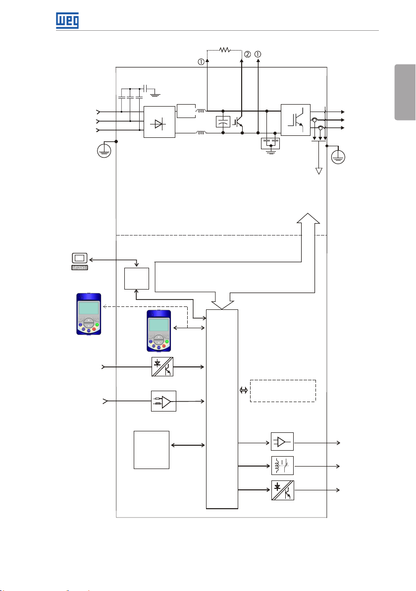
Mains power
supply
PC
R/L1/L
S/L2/N
T/L 3
PE
C3 RFI filter (*)
(available in
CFW700...C3...
Three-phase
rectifier
inverters)
Pre-
charge
DC+ DC-BR
DC link chokes
POWER
CONTROL
General Instructions
= DC bus connection
= Braking resistor
connection
U/T1
V/T2
Motor
W/T3
Inverter
with
RFI filter
DC link capacitor bank
CFW700...DB... inver ters)
Braking IGBT (available in
IGBT
transistors
Feedback:
- voltage
- current
PE
English
WPS software
WLP software
Keypad
(remote)
Digital inputs
DI1 to DI8
Analog
inputs
AI1 and AI2
RS-485
FLASH
memor y
module
(Slot 5)
Control power supply and interfaces
between power and control
Keypad
CC700
Control
board
with a
32 bits
"RISC"
CPU
Accessories
COMM 1
(Slot 3 - Green)
= Keypad (HMI)
(*) The capacitor to the ground of the C3 RFI filter (it is possible to meet the
requirements of category C2 with this filter on mechanics A models) must be
disconnected for IT net works and grounded delta power supplies. Please
refer to item 3.2.3.1 Input Connections on page 15.
Figure 2.1: Block diagram for the CFW700
Analog
outputs
AO1 and AO2
Digital output
DO 1 (R L1)
Digital outputs
DO2 to DO5
CFW700 | 5
Page 11
General Instructions
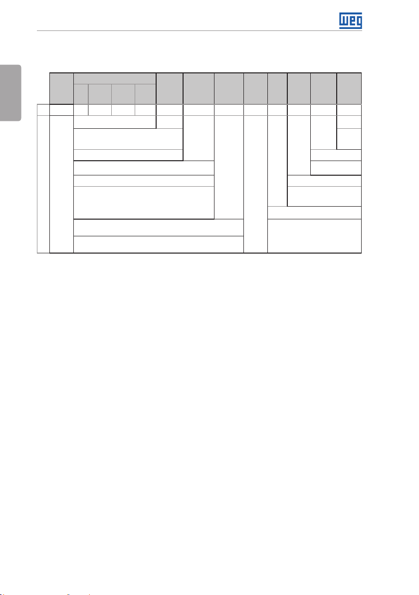
2.3 IDENTIFICATION
Table 2.1: Identification of the CFW700 inverters
English
Product
and
Series
Eg.: CFW700 A 03P6 T 4 DB 20 C3 DS Y1 W1 --- --
CFW700
Available options
Notes:
(1) The options available for each mo del are shown in Table 2.2 on p age 7.
(2) This option is not avai lable for frame size D inverters (the standard product is N ema1).
(3) This option is not availab le for frame size A inve rters with the N1 optio n (Nema1 enclosure) or I P21.
(4) It is pos sible to meet the req uirements of cate gory C2 with this f ilter on mechan ics A models. For fu rther detail s, see Table B.6 on page 226.
(5) Only applicabl e to models w ith degree of protection IP55, opt ion N12.
Model Identification
Rated
Output
Current
(4)
(2)
Number
of Power
Phases
Rated
Volta ge
Frame
Size
Refer to Table 2.2 on p age 7.
NB = withou t dynamic braki ng (valid only for
frame size E inverters).
DB = with dy namic braking. Blank = standard.
20 = IP20
21 = IP21 (not availa ble for frame size E inverter s). Blank = not available.
N1 = Nema1 enclos ure (UL Type 1) (protection de gree
accordi ng to IEC: IP21 for frame size s A, B and C and IP20
for frame s izes D and E).
N12 = IP55 (only for 200...240 V and 3 80...480 V models of
frame sizes B, C, D and E).
Blank = it i s not in acco rdance with the sta ndard conducted emissi on
levels.
C3 = accord ing to category 3 (C3) of IEC 61800-3, wi th built-in C3 RFI
fil ter.
Braking
(1)
Enclosure
Condu cted
(1)
Emission
Level
(1)
Safet y
Discon.
Stop
(5)
Switc h
(3)
Blank
= not
available
DS =
with
discon.
switch
Blank = not available.
Y1 = with STO function (Safe Torqu e Off)
accordi ng to EN 954-1/ISO 13849-1,
category 3.
External
Special
Control
Volta ge
W1 = 24 Vdc power supply,
indepe ndent of the control
voltage.
Special
Hardware
Software
Versi on
Versi on
Blank =
standard.
Sx =
special
software.
Hxx or K xx = special
hardware.
6 | CFW700
Page 12
General Instructions
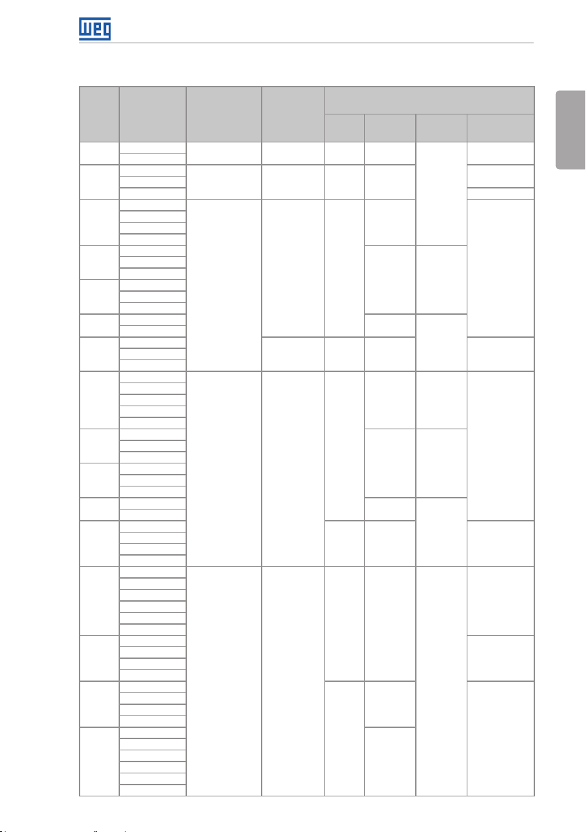
Table 2.2: Options available for each model according to the size, power supply, rated current and
voltage of the inverter
Frame
Size
A
A
A
B
C
D
E
A
B
C
D
E
B
C
D
E
Rated Output
Curre nt for ND
Overload
06P0 = 6.0 A
07P0 = 7.0 A
06P0 = 6.0 A
07P0 = 7.0 A
10P0 = 10 A Blank or C3
07P0 = 7.0 A
10P0 = 10 A
13P0 = 13 A
16P0 = 16 A
24P0 = 24 A
28P0 = 28 A
33P5 = 33.5 A
45P0 = 45 A
54P0 = 54 A
70P0 = 70 A
86P0 = 8 6 A
0105 = 105 A
0142 = 142 A
02 11 = 211 A
03P6 = 3.6 A
05P0 = 5.0 A
07P0 = 7.0 A
10P0 = 10 A
13P5 = 13.5 A
17P0 = 17 A
24P0 = 24 A
31P0 = 31 A
38P0 = 3 8 A
45P0 = 45 A
58P5 = 58.5 A
70P5 = 70.5 A
88P0 = 8 8 A
0105 = 105 A
0142 = 142 A
0180 = 180 A
02 11 = 211 A
02P9 = 2.9 A
04P2 = 4.2 A
07P0 = 7.0 A
10P0 = 10 A
12P0 = 12 A
17P0 = 17 A
22P0 = 22 A
27P0 = 27 A
32P0 = 32 A
44P0 = 44 A
22P0 = 22 A
27P0 = 27 A
32P0 = 32 A
44P0 = 44 A
53P0 = 53 A
63P0 = 63 A
80P0 = 80 A
0107 = 107 A
0125 = 125 A
0150 = 150 A
Number of
Power Phases
B = single-phase or
three-phase
S = Single-phase 2 = 200…240 V DB 20, 21 or N1
T = three-phase
T = three-phase 4 = 380 / 480 V
T = three-phase 5 = 50 0...600 V
Rated Voltage
2 = 200…240 V DB 20, 21 or N1
2 = 200…240 V DB
2 = 220…230 V
Available Options for the Remaining Identification
Braking
NB or
DB
DB
NB or
DB
DB 20, 21 or N1
NB or
DB
Codes o f the Inverte rs
(standard product is shown in bold)
Enclosure
(Protection
Degree)
20, 21 or N1
20, 21, N1
or N 12
21, N1 o r N12
20, N1 or N12 C30180 = 180 A
20, 21 or N1 Blank
20, 21, N1
or N 12
21, N1 o r N12
20, N1 or N12 C3
21 or N1
20 or N1
Discon.
Switch
Blank
Blank o r DS
Blank o r DS
Blank or DS
Blank or DS
Blank
Condu cted
Emission Level
Blank
Blank or C3
Blank or C3
Blank or C3
Blank or C3
CFW700 | 7
English
C3
C3
Page 13
General Instructions
2.4 LIST OF AVAILABLE MODELS
The available inverter models are listed in Table B.1 on page 212, Table B.2 on page 213
English
and Table B.3 on page 214.
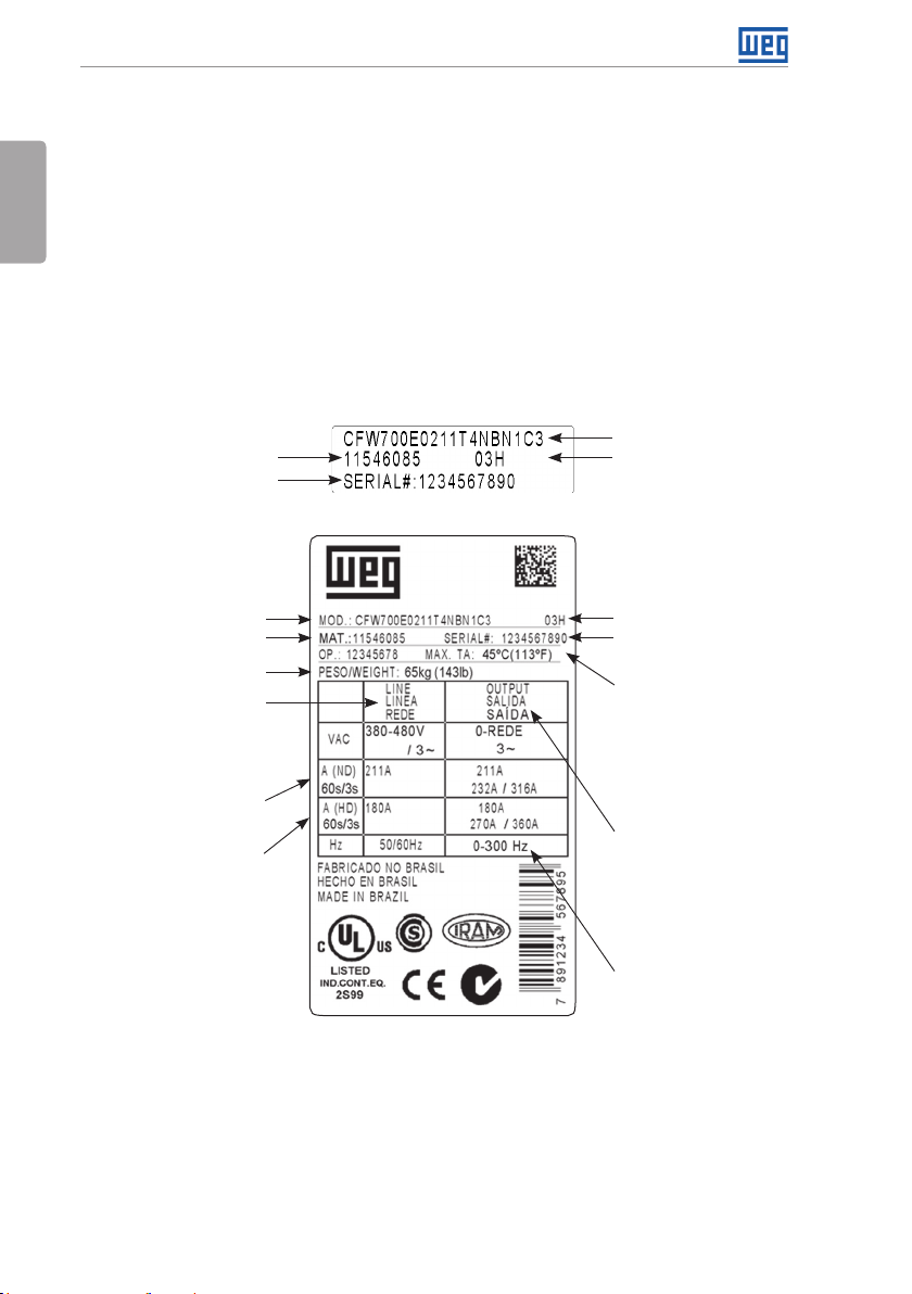
2.5 IDENTIFICATION LABELS
There are two nameplates on the CFW700: one complete nameplate is affixed to the side of the
inverter and a simplified one is located under the keypad. Please refer to Figure A.2 on page
202 to verify the position of these labels on the product. The nameplate under the keypad
allows the identification of the most important characteristics of the inverter even if they are
mounted side-by-side. When there is more than one inverter it is necessary to be careful not to
exchange the inverter covers (front cover in case of inverters frame sizes A, B or C and control
rack cover for inverters frame sizes D and E) because there are individual information labels
under the keypad of each inverter.
CFW700 model
Manufacturing dateWEG part number
Serial number
(a) Nameplate located under the keypad
CFW700 model
WEG part number
Inverter net weight
Input rated data (voltage,
number of phases, rated
currents for operation with
ND and HD overload cycles,
and frequency)
Current specifications
for operation with normal
overload cycle (ND)
Current specifications
for operation with heavy
overload cycle (HD)
(b) Nameplate affixed to the side of the inverter
Figure 2.2: (a) and (b) Nameplates
Manufacturing date
Serial number
Maximum ambient
temperature (without
derating) for ND overload
with open spaces for
ventilation around the
inverter (refer to the
dimensions A, B, C and D
in Figure B.3 on page 234)
Output rated data
(voltage, number of
phases, rated currents for
operation with ND and HD
overload cycles, overload
currents for 1 min and 3 s,
and frequency range)
The maximum output
frequency depends on the
settings of the motor rated
frequency, control mode
and inverter switching
frequency. For fur ther
details, see Table 8.1 on
page 61.
8 | CFW700
Page 14
General Instructions
2.6 RECEIVING AND STORAGE
The CFW700 comes packaged in a cardboard box up to frame size C inverter models. The
bigger models are packed in wooden box. There is an identification label affixed to the outside
of this package, the same one that is affixed to the side of the CFW700 inverter.
Follow the steps below to open the packaging of models larger than frame size C:
1. Put the shipping container over a flat and stable area with the assistance of another two
people.
2. Open the wood crate.
3. Remove all the packing material (the cardboard or styrofoam protection) before removing
the inverter.
Check the following items once the inverter is delivered:
Verify that the CFW700 nameplate corresponds to the model number on your purchase order.
Inspect the CFW700 for external damage during transportation.
Report any damage immediately to the carrier that delivered your CFW700 inverter.
If CFW700 is to be stored for some time before use, be sure that it is stored in a clean and dry
location that conforms to the storage temperature specification (between -25 °C and 60 °C
(-13 °F and 140 °F)). Cover the inverter to prevent dust accumulation inside it.
ATTENTION!
Capacitor reforming is required if drives are stored for long periods of time
without power. Refer to section 6.4 PREVENTIVE MAINTENANCE on page 53.
English
CFW700 | 9
Page 15

Installation and Connection
3 INSTALLATION AND CONNECTION
3.1 MECHANICAL INSTALLATION
English
3.1.1 Installation Environment
Avoid installing the inverter in an area with:
Direct exposure to sunlight, rain, high humidity, or sea-air.
Inflammable or corrosive gases or liquids.
Excessive vibration.
Dust, metallic particles, and oil mist.
Environment conditions for the operation of the inverter:
Inverter surrounding temperature: from -10 ºC up to Ta according to the Table B.4 on page 216.
For temperatures around the inverter greater than Ta and smaller than 60 °C (frame sizes
A, B, C and D), 40 °C (models with degree of protection IP55) and 55 °C (frame size E), it is
necessary to apply current reduction of 2 % for every degree Celsius (or 1.11 % each °F) up
to Ta.
Humidity: from 5 % to 95 % non-condensing.
Altitude: up to 1000 m (3,300 ft) - standard conditions (no derating required).
From 1000 m to 4000 m (3,300 ft to 13,200 ft) - current derating of 1 % each 100 m (or 0.3 %
each 100 ft) above 1000 m (3,300 ft) altitude.
From 2000 m to 4000 m (6,600 ft to 13,200 ft) above sea level - maximum voltage reduction
(240 V for 200...240 V models, 230 V for 220...230 V models, 480 V for 380...480 V models
and 600 V for 500...600 V models) of 1.1 % for each 100 m (330 ft) above 2000 m (6,600 ft).
Pollution degree: 2 (according to EN50178 and UL508C) with non-conductive pollution.
Condensation shall not originate conduction through the accumulated residues.
3.1. 2 Mounting Considerations
External dimensions, fixing holes position and net weight of the inverter are presented at Figure
B.2 on page 232 and Figure B.3 on page 234. Please refer to Figure B.4 on page 235 to
Figure B.11 on page 242 for more details of each inverter size.
Install the inverter upright on a flat surface. First place the screws on the surface where the
drive is going to be installed, install the drive and then tighten the screws.
Frame size E inverters with N1 option (CFW700E...N1...):
After fixing the inverter, install the upper Nema 1 kit on the inverter using the two M8 screws
provided with the product.
10 | CFW700
Page 16
Installation and Connection
Let the minimum clearances specified in Figure B.3 on page 234 in order to allow air circulation
for cooling. It is possible to assembly frame sizes A, B and C inverters with IP20 protection
degree (CFW700… 20…) side by side without lateral spacing, i.e., with the D distance presented
in Figure B.3 on page 234 equal to zero.
Do not install heat sensitive components right above the inverter.
ATTENTION!
When arranging two or more inverters vertically, respect the minimum
clearance A + B (Figure B.3 on page 234) and provide an air deflecting
plate so that the heat rising up from the bottom inverter does not affect the
top inverter.
Provide conduit for physical separation of the signal, control, and power
conductors (refer to section 3.2 ELECTRICAL INSTALLATION on page 11).
Please refer to Figure B.3 on page 234 for surface and flange mounting data. The inverter
dissipated power at rated condition for surface and flange mounting is presented in Table B.4
on page 216. Remove the drive mounting brackets for flange mounting. The protection degree
of the inverter outside the panel is IP55 for flange mounting. It is necessary to provide proper
seal for the opening where the inverter is installed to ensure the protection degree of the panel.
Example: sealing with silicone.
Please refer to Figure A.4 on page 204 for more details on the access to the control and
power terminals.
3.2 ELECTRICAL INSTALLATION
English
DANGER!
The following information is merely a guide for proper installation. Comply
with applicable local regulations for electrical installations.
Make sure the AC power supply is disconnected before starting the
installation.
CFW700 | 11
Page 17
Installation and Connection
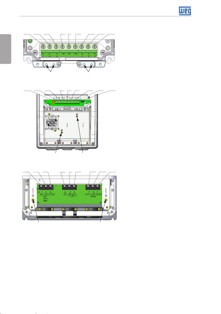
3.2 .1 Identification of the Power and Grounding Terminals
R/L1
S/L2
T/L 3
DC-
BR
DC+
U/T1
V/T2
W/T3
English
BR
BR
DC+
Ground
Ground
U/T1
V/T2
W/T3
Ground
(a) Frame sizes A, B and C
R/L1
S/L2
T/L 3
DC-
(b) Frame sizes B and C with degree of protection IP55
R/L1 S/L2 T/L 3 DC- DC+ U/T1 V/ T2 W/T3
Ground
Ground Ground
(c) Frame size D
R/L1, S/L2, T/L3: AC power supply.
DC-: this is the negative potential
terminal in the DC bus circuit.
BR: braking resistor connection.
DC+: this is the positive potential
terminal in the DC bus circuit.
U/T1, V/T2, W/T3: motor connection.
12 | CFW700
Page 18
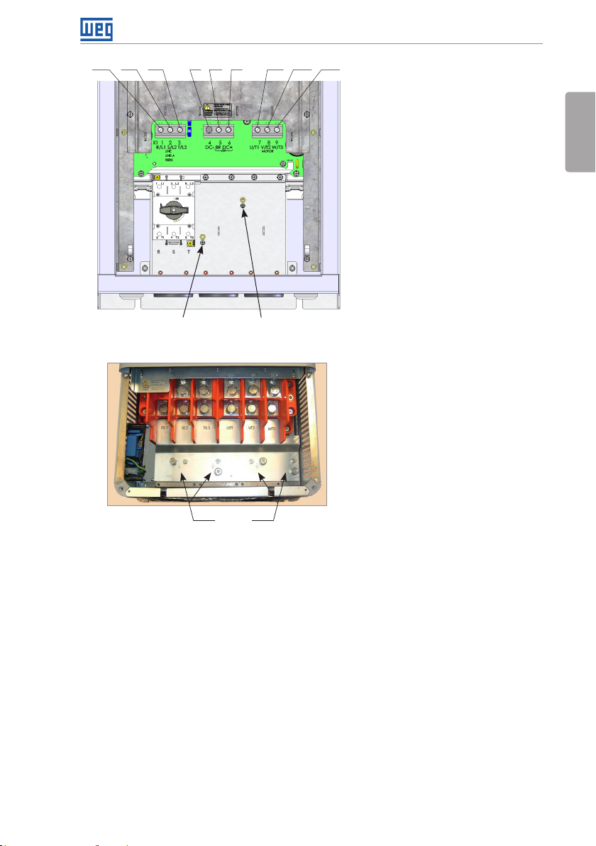
R/L1 S/L2 T/ L 3 DC- DC+ U/T1 V/ T2 W/T3BR
(d) Frame size D with degree of protection IP55
Ground
Ground
Installation and Connection
English
R/L1, S/L2, T/L3: AC power supply.
U/T1, V/T2, W/T3: motor
connwwection.
DC+: this is the positive potential
terminal in the DC bus circuit.
BR: braking resistor connection.
DC-: this is the negative potential
terminal in the DC bus circuit.
Ground
(4xM8, 4xM5)
(e) Frame size E
CFW700 | 13
Page 19
Installation and Connection
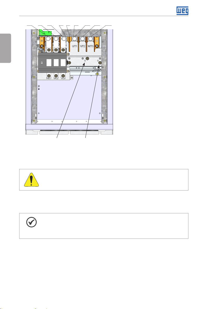
R/L1 S/L2 T/ L 3 DC- DC+ U/T1 V/ T2 W/T3BR
English
(f) Frame size E with degree of protection IP55
Ground
Figure 3.1: (a) to (f) Power terminals and grounding points - frame sizes A to E
Ground
3.2.2 Power / Grounding Wiring and Fuses
ATTENTION!
Use proper cable lugs for the power and grounding connection cables.
Refer to Table B.1 on page 212, Table B.2 on page 213 and Table B.3 on page 214 for the
recommended wiring and fuses and Table B.5 on page 223 for the specifications of the power
terminals.
NOTE!
The gauges values presented in Table B.1 on page 212, Table B.2 on page 213
and Table B.3 on page 214 are for reference only. Installation conditions and the
maximum permitted voltage drop shall be considered for the proper wiring sizing.
Input fuses
The fuses to be used at the input must be HS (High-Speed) type with I
value indicated in the Table B.1 on page 212, Table B.2 on page 213 and Table B.3 on
page 214 (consider extinction current value in cold situation (it is not the fusion value)), to
protect the inverter diode rectifiers and input wiring.
In order to meet UL requirements, use class J fuses at the inverter supply with a current not
higher than the values presented in Table B.1 on page 212, Table B.2 on page 213 and
Table B.3 on page 214.
2
t equal or lower the
14 | CFW700
Page 20
Installation and Connection
Optionally, slow blow fuses can be used at the input. They shall be sized for 1.2 x the rated
input current of the inverter. In this case, the installation is protected against short-circuit, but
not the inverter input rectifier. This may result in major damage to the inverter in the event of
an internal component failure.
3.2.3 Power Connections
English
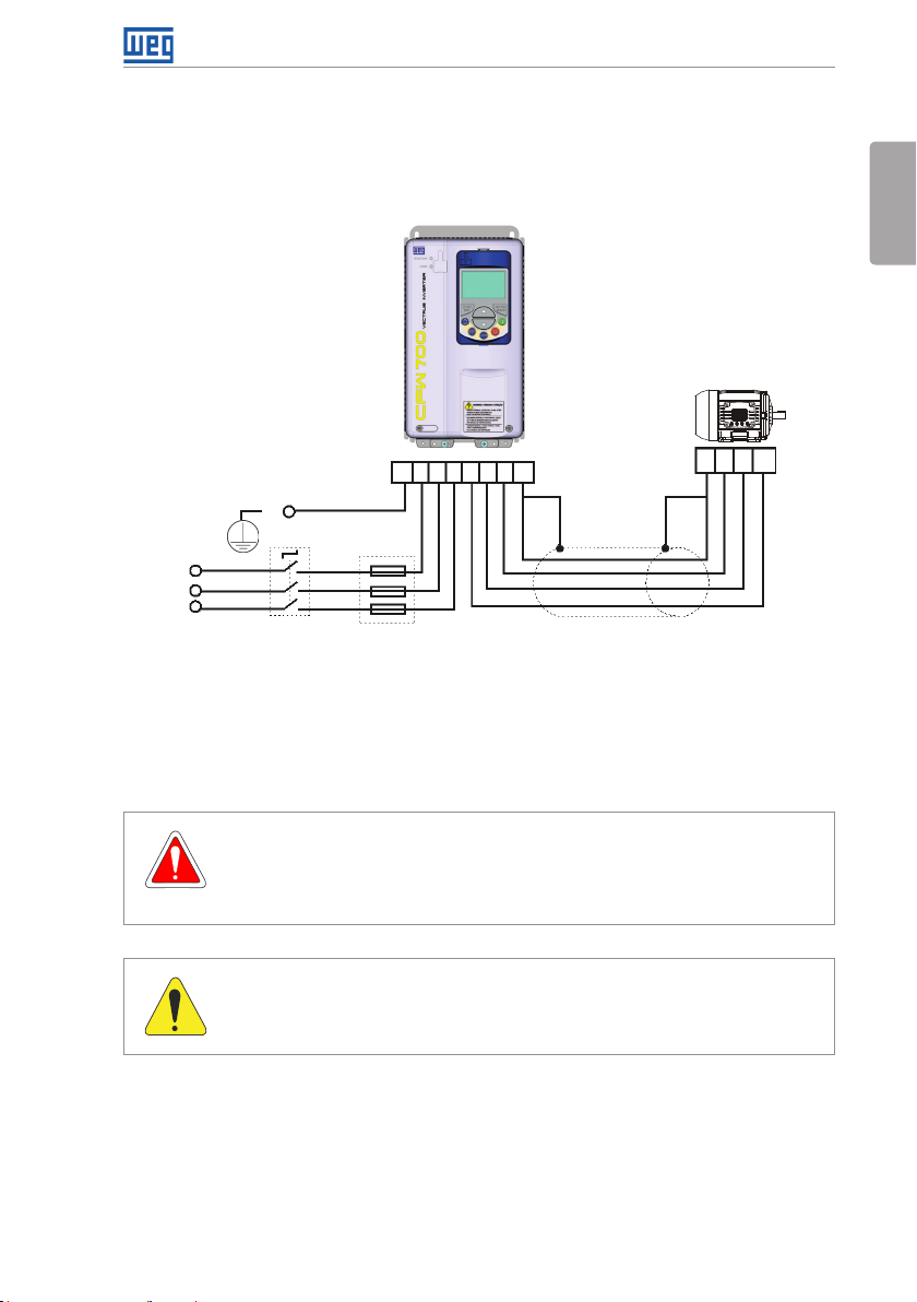
PE R S T U V W PE
PE
Shielding
R
S
T
Power
supply
The switch-disconnector is not necessary if the inverter has the DS optional item (with
Disconnect
switch
Fuses
Figure 3.2: Power and grounding connections
PE W V U
switch-disconnector).
3.2.3.1 Input Connections
DANGER!
Provide a disconnect device for the input power supply of the inverter.
This device shall disconnect the input power supply for the inver ter when needed
(for instance, during servicing).
ATTENTION!
The power supply that feeds the inverter shall have a solid grounded neutral.
In case of IT networks, follow the instructions described below.
CFW700 | 15
Page 21

Installation and Connection
ATTENTION!
In order to be able to use the CFW700 with built-in C3 RFI filter (frame sizes A, B, C
English
and D with optional RFI f ilter and all frame size E inverter models – CFW700…C3…)
in IT networks (neutral conductor not grounded or grounded via a high ohmic value
resistor) or in corner-grounded delta systems, it is necessary to remove some RFI
filter components (capacitor for frame sizes A, B, C and D and capacitor and the
MOV for frame size E) connected to the ground by removing the screws indicated
in Figure A.8 on page 208 for inverter frame sizes A, B, C and D and changing the
position of the J1 jumper on the PRT1 board from (XE1) to “NC” (XIT), according
to the Figure A.8 on page 208 for inverter frame size E.
AC power supply considerations
Suitable for use on a circuit capable of delivering not more than 100.000 A
Ampères at 240 V, 480 V or 600 V maximum, when protected by Class J fuses (for 240 V
symmetrical
rms
and 480 V models) or special purpose fuses (for 600 V).
3.2.3.2 Dynamic Braking (standard built-in for frame sizes A, B, C and D and optional built-in for frame size E - CFW700...DB...)
Refer to Table B.1 on page 212, Table B.2 on page 213 and Table B.3 on page 214 for
the following dynamic braking specifications: maximum current, resistance, RMS current (*)
and cable gauges.
The power rating of the dynamic braking resistor is a function of the deceleration time, the load
inertia and the resistant torque.
Dynamic braking installing procedure:
Install the braking resistor between the power terminals DC+ and BR.
Use twisted cable for the connection. Separate these cables from the signal and control
cables.
Size the cables according to the application, respecting the maximum and effective currents.
If the braking resistor is installed inside the inverter cabinet, consider its additional dissipated
energy when sizing the cabinet ventilation.
The thermal protection of the dynamic brak ing resistor must be provided ex ternally using a thermal
relay in series with the resistor and/or a thermostat in contact with the resistor frame, connected
so as to switch the input power supply of the inverter, as shown in Figure 3.3 on page 17.
Set P0151 and P0185 to their maximum values (400 V or 800 V) when using dynamic braking.
The DC link voltage actuation level of the dynamic braking is set by parameter P0153 (Dynamic
Braking Level).
16 | CFW700
Page 22
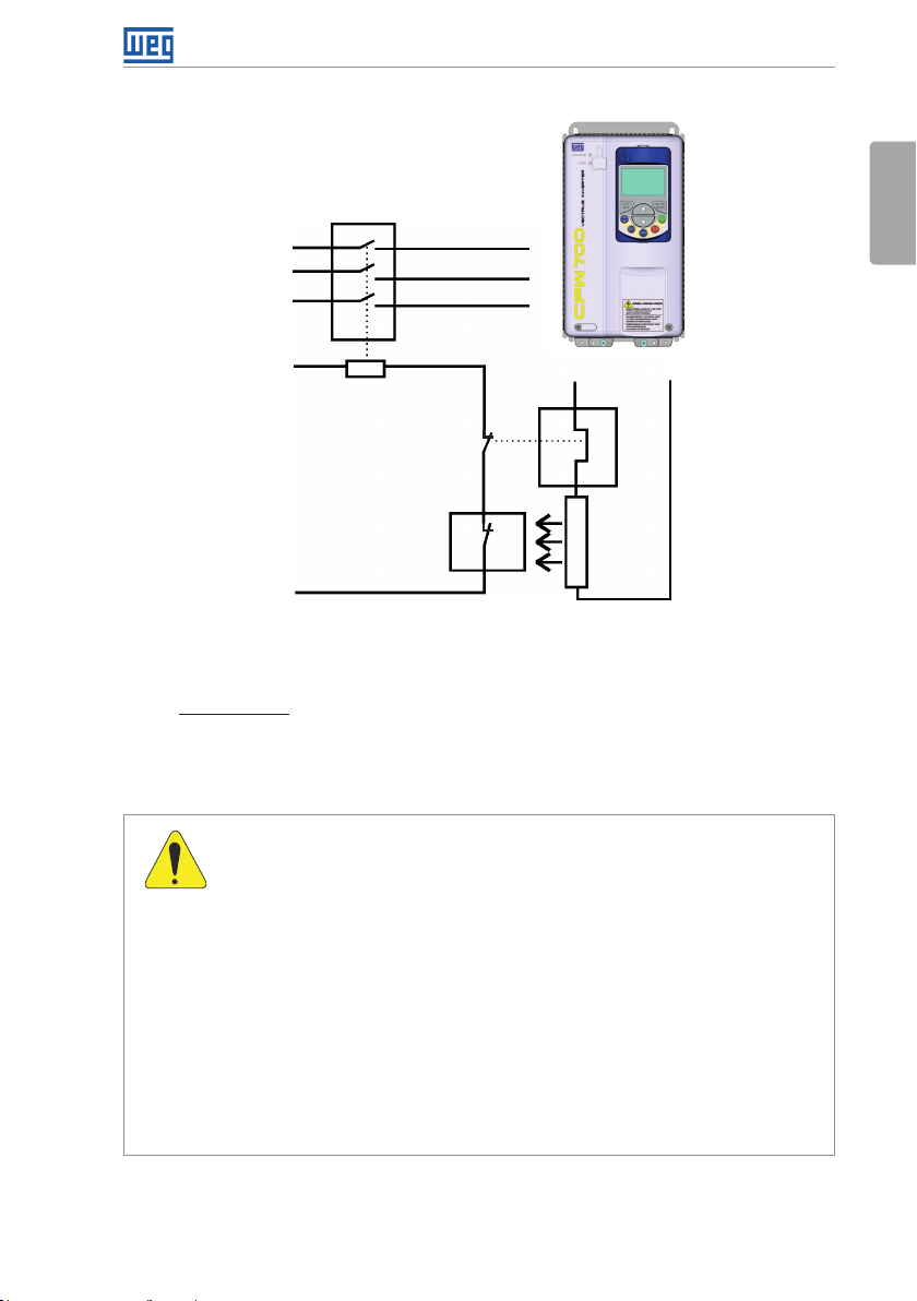
Power
supply
Contactor
Installation and Connection
CFW700
R
S
T
English
BR
Thermal
Control power
supply
Thermostat
Figure 3.3: Connection of the braking resistor
relay
(*) The effective braking current can be calculated as follows:
I
. √tbr (min)
max
I
=
effect ive
5
3.2.3.3 Output Connections
ATTENTION!
The inverter has an electronic motor overload protection that shall be adjusted
according to the driven motor. When several motors are connected to the
same inverter, install individual overload relays for each motor.
The motor overload protection available for the CFW700 is in accordance
with UL508C as per the following information:
- "Trip" current equal to 1.25 times the motor rated current (P0401) adjusted
in the "Oriented Start-up" menu.
- The maximum value of P0398 (Motor Service Factor) is 1.15.
- Parameters P0156, P0157 and P0158 (Overload Current at 100 %,
50 % and 5 % of the rated speed, respectively) are automatically adjusted
when the parameters P0401 (Motor Rated Current) and/or P0406 (Motor
Ventilation) are changed on the “Oriented Start-up” menu. If the parameters
P0156, P0157 and P0158 are set manually, the maximum allowed value
is 1.05 x P0401.
DC+
Braking
resi stor
CFW700 | 17
Page 23
Installation and Connection
ATTENTION!
If a disconnect switch or a contactor is installed between the inverter and the
English
motor, never operate them with a spinning motor or with voltage at the inverter
output.
The characteristics of the cable used for the inverter and motor interconnection, as well as
the physical location are extremely important to avoid electromagnetic interference in other
equipment and to not affect the life cycle of motor windings and motor bearings controlled by
inverters.
Keep motor cables away from other cables (signal cables, sensor cables, control cables, etc.),
according to item 3.2.6 Cable Distances on page 23.
Connect a fourth cable between the motor ground and the inverter ground.
When using shielded cables for connecting the motor:
Follow the recommendations of IEC60034-25.
Use low impedance connection to high frequencies to connect the cable shield to ground.
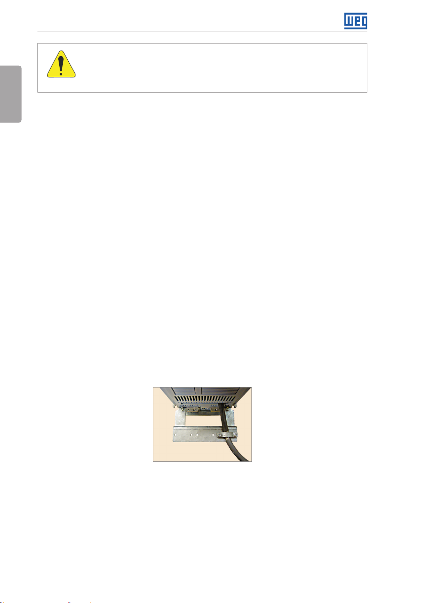
Using parts supplied with the drive. See item below.
For inverter frame sizes A, B and C there is an accessory called “Shielding kit for power
cables PCSx-01” (see section 7.2 ACCESSORIES on page 58), which can be mounted at
the bottom of the cabinet – the Figure 3.4 on page 18 shows an example. The shielding
kit for power cables PCSx-01 goes along with inverters with optional internal C3 RFI filter
(CFW700...C3...). The grounding for the motor cable shield on inverter frame sizes D and E is
already provided in the standard inverter cabinet. This is also provided on the “Nema1 Kits
(KN1x-01)” of the inverter frame sizes A, B and C.
For frame sizes B and C with degree of protection IP55, the accessory "PCSC-03 power
cable shield kit" is available, and for frame size D and E with degree of IP55 use the standard
accessories for shielding. The PCSC-03 shield kit comes with the inverter as optional item N12.
Figure 3.4: Motor cable shielding connection with PCSx-01 accessory
18 | CFW700
Page 24

Installation and Connection
3.2.4 Grounding Connections
DANGER!
The inverter shall be connected to a Protective Ground (PE).
Use the minimum ground wiring gauge as indicated in the Table B.1 on page
212, Table B.2 on page 213 and Table B.3 on page 214.
Connect the inverter grounding connections to a ground bus bar, to a single
ground point, or to a common grounding point (impedance ≤ 10 Ω).
The neutral conductor of the network shall be solidly grounded; however,
this conductor shall not be used to ground the inverter.
It is necessary to use a copper cable with 10 mm
2
minimum or 2 cables with
the same wire gauge as specified in Table B.1 on page 212, Table B.2 on
page 213 and Table B.3 on page 214 for connecting the inverter to the
ground protection to be in accordance with IEC61800-5-1 since the leakage
current is greater than 3.5 mA AC.
3.2.5 Control Connections
The control connections (analog inputs/outputs and digital inputs/outputs), shall be performed
in connector XC1 of the CC700 Control Board. Functions and typical connections are presented
in Figure 3.5 on page 21.
English
CFW700 | 19
Page 25
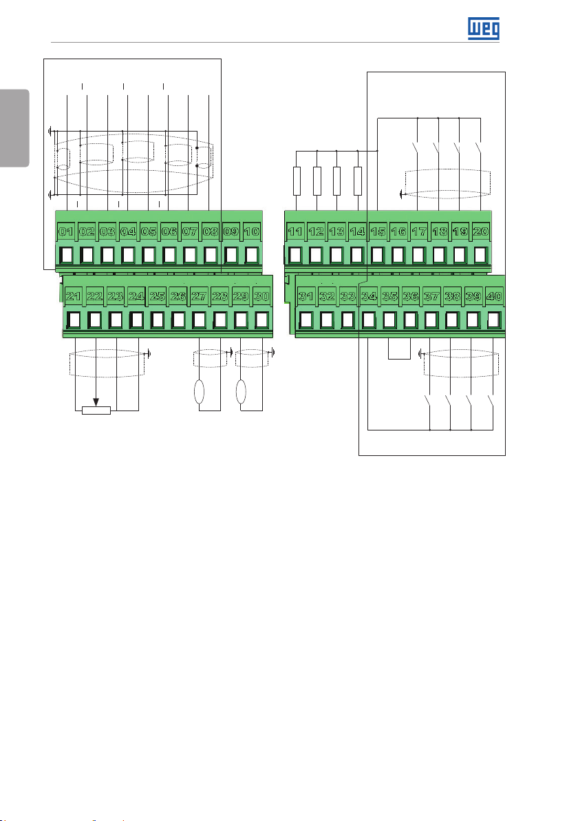
Installation and Connection
Linedrive encoder or push-pull
A
A
+V
English
Blue
White
A
+5 V-ENC
REF+
(1) Refer to Figure 3.5 on page 21 (b) for the open-collector encoder connection.
(2) Refer to Figure 3.5 on page 21 (c) for active low digital inputs connection.
B
Red
Green
Yel lo w
B
B
A
≥5 kΩ
AI1-
AI1+
REF-
(1)
Z
Z
B
Pink
Z
AI2+
GND
GreyZ
Brown
DO2
DO3
DO4
>300 Ω
>300 Ω
RL1-NF
>300 Ω
RL1-C
A - RS-485
GND-ENC
AI2-
rpm
AO1
B - RS-485
amp
AO2
AGND (24 V)
AGND (24 V)
+24 V
DO5
>300 Ω
RL1-N A
+24 V
Active high digital inputs
DI5
GND (24 V)
COM
GND (24 V)
DI1
(2)
DI6
DI7
DI8
DI2
DI3
DI4
(a) Linedrive encoder or push-pull and active high digital inputs
20 | CFW700
Page 26
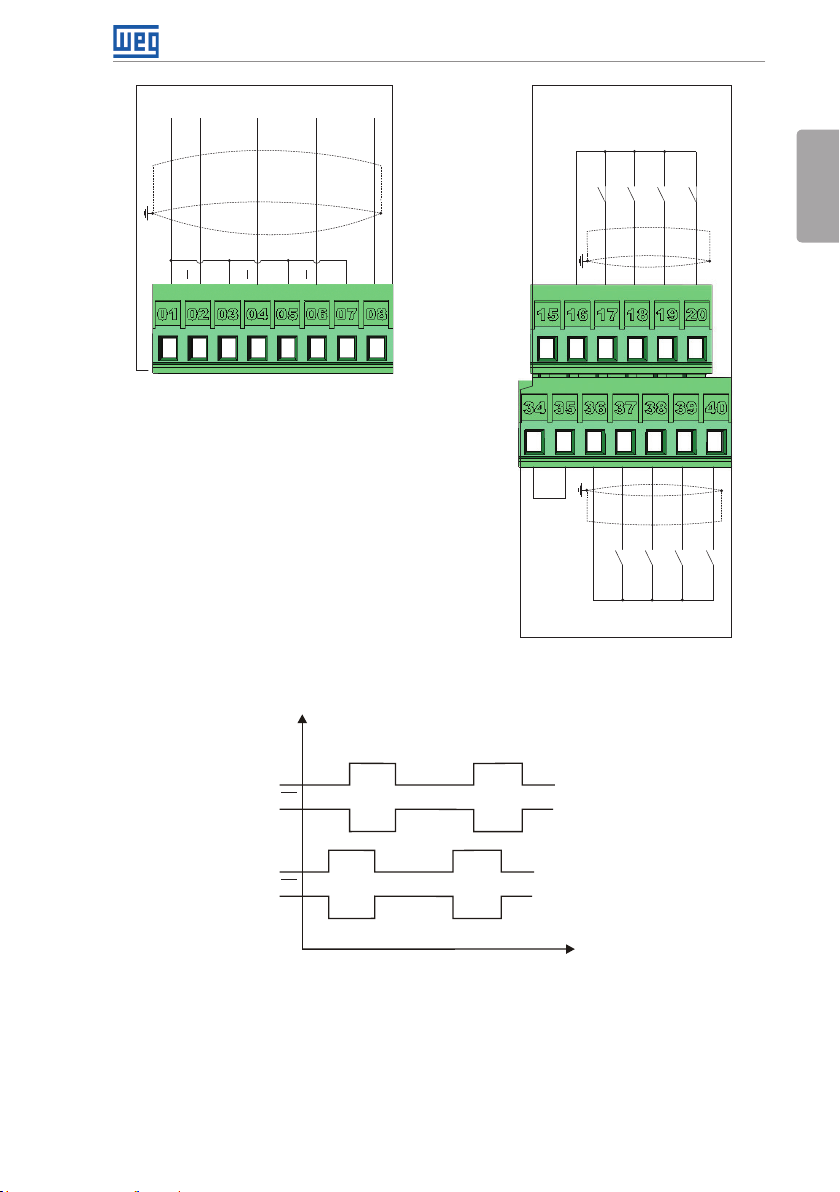
Installation and Connection
Open collector encoder
+V(5 V )
A A
+5 V-ENC
Z
Z
Z
B
BBA
(b) Encoder with open collector
output
Figure 3.5: (a) to (c) XC1 connection terminals
Signal
Active low digital inputs
+24 V
DI5
DI6
DI7
GND (24 V)
DI8
English
GND-ENC COM
+24 V
COM
GND (24 V)
DI1
DI2
DI3
DI4
(c) Active low digital inputs
A
A
B
B
Time
Figure 3.6: Sequence of the encoder signals
Refer to Figure A.3 on page 202 to find the control board, the XC1 connector (control
signals), the S1 DIP-switches (to select the type of signal of the analog inputs and outputs)
and S2 (RS-485 network termination) and slots 3 and 5 for accessories (see section 7.2
ACCESSORIES on page 58).
The CFW700 inverters are supplied with the digital inputs configured as active high and the
CFW700 | 21
Page 27
Installation and Connection
analog inputs and outputs configured for voltage signal 0...10 V.
English
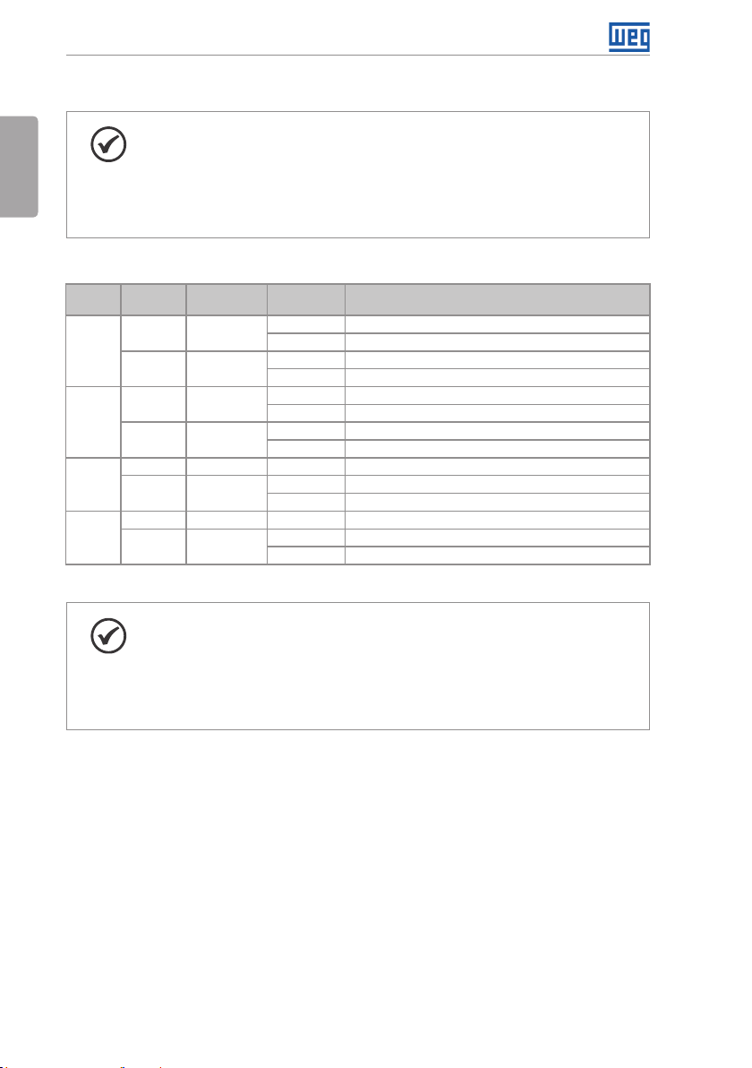
NOTE!
To be able to use the analog input and/or output as current signals, it is
necessary to change the switch S1 and the related parameters as per Table
3.1 on page 22. In order to set the analog inputs to bipolar voltage signal
(-10…10 V), it is necessary to set P0233 and P0238 according to Table 3.1 on
page 22. Refer to the CFW700 programming manual for more information.
Table 3.1: Configuration of the switch for the analog input and output signals selection
Input/
Output
Signal
Voltage S1.2 = OFF
AI1
Current S1.2 = ON
Voltage S1.1 = OFF
AI2
Current S1.1 = ON
Voltage S1.3 = ON
AO1
Current S1.3 = OFF
Voltage S1.4 = ON
AO2
Current S1.4 = OFF
(*) Factory setting.
S1 Switch
Settings
Signal
Range
(*)
0…10 V
(*)
-10…10 V P0233 = 4
P0233 = 0 (direct reference) or 2 (reverse reference).
Parameter Settings
0...20 mA P0233 = 0 (direct reference) or 2 (reverse reference).
4...20 mA P0233 = 1 (direct reference) or 3 (reverse reference).
(*)
0…10 V
(*)
-10…10 V P0238 = 4
P0238 = 0 (direct reference) or 2 (reverse reference).
0...20 mA P0238 = 0 (direct reference) or 2 (reverse reference).
4...20 mA P0238 = 1 (direct reference) or 3 (reverse reference).
(*)
0...10 V
(*)
P0253 = 0 (direct reference) or 2 (reverse reference).
0...20 mA P0253 = 0 (direct reference) or 2 (reverse reference).
4...20 mA P0253 = 1 (direct reference) or 3 (reverse reference).
(*)
0...10 V
(*)
P0256 = 0 (direct reference) or 2 (reverse reference).
0...20 mA P0256 = 0 (direct reference) or 2 (reverse reference).
4...20 mA P0256 = 1 (direct reference) or 3 (reverse reference).
NOTE!
Settings of the S2 switch:
S2.1 = ON and S2.2 = ON: RS-485 is ON.
S2.1 = OFF and S2.2 = OFF: RS-485 is OFF.
The factory default for the S2.1 and S2.2 switches are OFF.
Other combinations of switch S2 are not allowed.
Technical specifications for the encoder and the encoder cable as shown in Table 3.2 on page
23.
22 | CFW700
Page 28

Installation and Connection
Table 3.2: Technical specifications for the encoder and the encoder cable
Characteristics Specifications
Power supply 5 V
2 channels in qua drature (90º) + zero pulses with co mplementar y outputs
(differentials) or open-collector.
A, A, B, B, Z and Z
Available for 2 channels: A, A, B, B.
If the channel zis not used, leave the terminals XC1: 6 and 7 not
connected. Noother setting are necessary.
The cable shield must be connected to ground through devices on
control shield plate (see Figure 3.5 on page 21).
Encoder
Encoder
cable
Channels
Signals
Output circuit Linedrive type, push-pull or open-collector. Maximum voltage of 12 V.
Isolation Electronic circuit isolated from the encoder frame.
Pulses Recommended number of pulses per rotation = 1024 ppr.
Frequency Maximum allowed = 100 kHz.
Type of cable Balanced cable shield (for differential signals operation).
Connection
Distance ≥ 25 cm of other wiring.
Isolation Use metal conduit.
Length Maximum = 10 m.
Follow instructions below for the proper installation of the control wiring:
1. Wire gauge: 0.5 mm² (20 AWG) to 1.5 mm² (14 AWG).
2. Maximum tightening torque: 0.50 N.m (4.50 lbf.in).
3. Use shielded cables for the connections in XC1 and run the cables separated from the
remaining circuits (power, 110 V / 220 Vac control, etc.), according to item 3.2.6 Cable
Distances on page 23. If control wiring must cross other cables (power cables for instance),
make it cross perpendicular to the wiring and provide a minimum separation of 5 cm (1.9 in)
at the crossing point.
English
Refer to item 3.2.6 Cable Distances on page 23, for the proper cable distances.
Isolate with tape
Inverter
side
Do not ground
(a) Cable shield connection
Figure 3.7: (a) and (b) Shield connection
(b) Connection sample of the shield to
ground
4. Relays, contactors, solenoids or coils of electromechanical brakes installed close to the
inverter may eventually create interferences in the control circuitry. To eliminate this effect,
RC suppressors (with AC power supply) or free-wheel diodes (with DC power supply) shall
be connected in parallel to the coils of these devices.
3.2.6 Cable Distances
The power cables and control cables must be separated (relay output cables and other control
cables) according to Table 3.3 on page 24.
CFW700 | 23
Page 29

Installation and Connection
Table 3.3: Cable distances
Rated Output
English
Inverter Current
≤ 24 A
≥ 28 A
Cable Length(s)
≤ 100 m (330 ft)
> 100 m (330 ft)
≤ 30 m (100 ft)
> 30 m (100 ft)
Minimum Separation
Distance
≥ 10 cm (3.94 in)
≥ 25 cm (9.84 in)
≥ 10 cm (3.94 in)
≥ 25 cm (9.84 in)
3.3 INSTALLATION ACCORDING TO THE EUROPEAN DIRECTIVE OF ELECTROMAGNETIC COMPATIBILITY
The inverters with C3 option (CFW700...C3...) have internal C3 RFI filter to reduce electromagnetic
interference. These inverters, when properly installed, meet the requirements of “EMC Directive
89/336/EEC” with the 93/68/EEC supplement.
The CFW700 inverter series has been designed only for industrial applications. Therefore, the
emission limits of harmonic currents defined by the standards EN 61000-3-2 and EN 61000-3-2/A
14 are not applicable.
3.3.1 Conformal Installation
1. Inverters with built-in C3 RFI filter CFW700...C3...
2. Frame sizes A to D inverters with built-in C3 RFI filter capacitors grounding screws and frame
size E with J1 cable in the position (XE1). For more information see Figure A.8 on page
208.
3. Shielded output cables (motor cables) and connect the shield at both ends (motor and
inverter) with a low impedance connection for high frequency. Use PCSx-01 kit supplied with
frame sizes A, B and C inverters. For frame sizes B and C with degree of protection IP55,
use the PCSC-03 shield kit. For frame sizes D and E inverters use the clamps supplied with
the product. Ensure good contact between the cable shield and the clamps. Refer to Figure
3.4 on page 18 and keep the proper separation from other cables according to item 3.2.6
Cable Distances on page 23. The maximum motor cable length and conduction and
radiated emission levels are presented at Table B.6 on page 226. Use an external RFI filter
at the input of the inverter if necessary to have a lower emission level and/or a longer motor
cable length. For more information (RFI filter commercial reference, motor cable length and
emission levels) refer to Table B.6 on page 226.
4. Shielded control cables and separate the remaining cables according to item 3.2.6 Cable
Distances on page 23.
5. Inverter grounding according to the instructions on item 3.2.4 Grounding Connections on
page 19.
6. Grounded power supply.
24 | CFW700
Page 30

3.3.2 Emission and Immunity Levels
Table 3.4: Emission and immunity levels
EMC Phenomenon
Emission:
Mains Terminal Disturbance Voltage
Frequency Range: 150 kHz to 30 MHz)
Electromagnetic Radiation Disturbance
Frequency Range: 30 MHz to 1000 MHz)
Immunity:
Electrostatic Discharge (ESD) IEC 61000-4-2
Fast Transient-Burst IEC 61000-4-4
Conducted Radio-Frequency Common
Mode
Surge Immunity IEC 61000-4-5
Radio-Frequency Electromagnetic Field IEC 61000-4-3
Basic
Standard
IEC/EN61800-3
IEC 61000-4-6
Installation and Connection
Level
It depends on the inverte r model and the motor
cable length.
See Table B.6 on page 226.
4 kV for contact discharge and 8 kV for air
discharge.
2 kV / 5 kHz (coupling capacitor) power input
cables;
1 kV / 5 kHz control cables, and remote
keypad cables;
2 kV / 5 kHz (coupling capacitor) motor output
cables.
0.15 to 80 MHz; 10 V; 80 % AM (1 kHz).
Power supp ly cable, motor, control an d remote
keypad (HMI).
1.2/50 μs, 8/20 μs;
1 kV line-to-line coupling;
2 kV line-to-ground coupling.
80 to 1000 MHz;
10 V/m;
80 % AM (1 kHz).
English
Refer to Table B.6 on page 226 for conducted and radiated emission levels accomplished
with and without external RFI filter. The reference model for the external filter is also presented.
CFW700 | 25
Page 31

Keypad (HMI) and Basic Programming
4 KEYPAD (HMI) AND BASIC PROGRAMMING
4.1 INTEGRAL KEYPAD - HMI-CFW700
English
The integral keypad can be used to operate and program (view / edit all parameters) of the
CFW700 inverter. There are two operation modes in the keypad: monitoring and programming.
The key functions and display indications of the keypad may change according to the operation
mode. The programming mode consists of three levels.
- When in monitoring mode: press this key
- When in monitoring mode: press this
key to increase the speed.
- When in programming mode, level 1:
press this key to go back to the
previous group.
- When in programming mode, level 2:
press this key to go to the next
parameter.
- When in programming mode, level 3:
press this key to increase the
parameter value.
- When in programming mode, level
1: press this key to go back to the
monitoring mode.
- When in programming mode, level 2:
press this key to go back to the level 1.
- When in programming mode, level 3:
press this key to cancel the new value
(the value will not be saved) and it will
return to level 2 of the programming
mode.
- USB
communication port
(1)
to decrease the speed.
- When in programming mode, level 1:
press this key to go to the next group.
- When in programming mode, level 2:
press this key to go back to the previous
parameter.
- When in programming mode, level 3:
press this key to decrease the parameter
value.
- When in monitoring mode: press this
key to enter in the programming mode.
- When in programming mode, level 1:
press this key to select the desired
parameter group – it shows the
parameters of the selected group.
- When in programming mode, level 2:
press this key to show the parameter
– it shows the parameter value for its
modification.
- When in programming mode, level 3:
press this key to save the new parameter
value – it returns to level 2 of the
programming mode.
- Press this key to define the motor
rotation.
This option is active when:
P0223 = 2 or 3 in LOC and/or
P0226 = 2 or 3 in REM.
- Press this key to change between
LOCAL and REMOTE mode.
This option is active when:
P0220 = 2 or 3.
- Press this key to accelerate the motor up to the speed set in P0122. The motor speed is maintained
while the key is pressed. When the key is released the motor decelerates up to its complete stop.
This function is active when all the following conditions are met:
1. Start/Stop = Stop.
2. General Enable = Active.
3. P0225 = 1 in LOC and/or P0228 = 1 in REM.
(1) Available from the serial number 1024003697.
26 | CFW700
Figure 4.1: Operator keys
- Press this key to accelerate the motor
according to the acceleration ramp time.
This option is active when:
P0224 = 0 in LOC and/or
P0227 = 0 in REM.
- Press this key to decelerate the motor
according to the deceleration ramp time.
This option is active when:
P0224 = 0 in LOC and/or
P0227 = 0 in REM.
Page 32

NOTE!
It is necessary to set the password at P0000 for parameter modification.
Otherwise the parameters contents can only be viewed.
The default password for P0000 is 5. It is possible to change the password at
P0200. Refer to the CFW700 programming manual.
Local/Remote
(commands and
Motor rotation
Menu (parameters
group selection) –
only one parameter
group is shown at
each time.
Main display
references source)
Figure 4.2: Display sections
Parameter groups available at the Menu:
Keypad (HMI) and Basic Programming
English
Inverter status
Secondary display
Variable unit
(shows the value of
the main display)
Variable monitoring
bar graph
PARAM: all parameters.
READ: only the reading parameters.
MODIF: only the parameters changed compared to the factory default.
BASIC: basic application parameters.
MOTOR: parameters related to motor data control.
I/O: parameters related to the digital and analog inputs/outputs.
NE T: parameters related to the communication protocol.
HMI: parameters for the keypad configuration.
SPLC: parameters related to the SoftPLC function.
STARTUP: parameters for the Oriented Start-up.
CFW700 | 27
Page 33

Keypad (HMI) and Basic Programming
Inverter status:
LOC: local reference.
English
REM: remote reference.
: motor rotation according to the arrows.
CONF: configuration. It indicates that the inverter is in the Oriented Start-up routine or with
incompatible parameter programming. Refer section Incompatibility Between Parameters in
the programming manual of the CFW700.
SUB: DC link undervoltage.
RUN: inverter enabled and/or DC braking activated.
Monitoring Mode
It is the initial state of the keypad after power up and startup screen,
with the factory default values.
The Menu is not active in this mode.
Main display, secondary display and monitoring bar show the values of
the parameters defined at P0205, P0206 and P0207.
From the monitoring mode, pressing the ENTER/MENU key will switch
to the programming mode.
Programming Mode
Level 1:
This is the first level of the programming mode. It is possible to chose
the parameter group by using the and keys.
The main display, secondary display and monitoring bar are not shown
at this level.
Press the ENTER/MENU key to go to the second level of programming
mode - parameters selection.
Press the BACK/ESC key to go back to the monitoring mode.
Level 2:
The parameter number is displayed on the main display and its value
on the secondary display.
Use the and keys to find the desired parameter.
Press the ENTER/MENU key to go to level 3 of the programming mode
– parameters value changing.
Press the BACK /ESC key to return to level 1 of the programming mode.
Level 3:
The parameter values is shown at the main display and the parameter
number at the secondary display.
Use the and keys to change the valu e of the selected pa rameter.
Press ENTER/MENU key to confirm the modification (save the new
value) or BACK/ESC key to cancel the modification (do not save the
new value). In both cases, the keypad returns to the second level of the
programming mode.
Figure 4.3: Keypad operation modes
The keypad can be installed or removed from the inverter with or without AC power applied
to the inverter.
The HMI supplied with the product can also be used for remote command of the inverter. In
this case, use a cable with male and female D-Sub9 (DB-9) connectors wired pin to pin (mouse
28 | CFW700
Page 34

Keypad (HMI) and Basic Programming
extension type) or a market standard Null-Modem cable. Maximum length of 50 m (164 ft). It
is recommended the use of the M3 x 5.8 standoffs supplied with the product. Recommended
torque: 0.5 N.m (4.5 lbf.in).
Use the keypad frame accessory to assembly the keypad on the panel door or control table
(see section 7.2 ACCESSORIES on page 58, or perform the drilling as shown in Figure A.5
on page 205).
NOTE!
A list of parameters is supplied with the product, for additional information on
each parameter refer to the CFW700 programming manual provided in the
CD-ROM that accompanies the product or it can be downloaded at the WEG
homepage - www.weg.net.
4.2 APPLICATIONS
The CFW700 has some features that allow better matching the inverter commands to the
application. These features were grouped into a set of applications and can be as simple as the
forward and reverse command, or more elaborated such as a PID controller.The applications
were implemented using the SoftPLC function, in other words, ladder programming applicative
built-in to the CFW700 inverter. It allows the user that has the WLP and the built-in implemented
applicative to change it and use it as an user applicative.
Parameter P1003 allows selecting an application and uploading it to the CFW700. The CFW700
has following applications built-in:
PID Regulator.
English
Electronic Potentiometer (E.P.).
Multispeed.
3-Wire Start/Stop.
Forward/Reverse Run.
4.2.1 PID Regulator Application
The CFW700 has the PID REGULATOR application that can be used to control a closed loop
process. This application sets proportional, integral and derivative regulator superimposed to
the regular speed control of the CFW700 inverter.
The CFW700 will compare the setpoint with the process variable and control the motor speed
trying to eliminate any error and keeping the process variable equal to the setpoint. The setting
of the P, I and D gains determines how fast the inverter will respond to eliminate this error.
Application examples:
Flow control or pressure in a pipe system.
Temperature of a furnace or oven.
Dosing of chemicals in tanks.
CFW700 | 29
Page 35

Keypad (HMI) and Basic Programming
The following example defines the terms used by the PID controller.
A pump used in a water pumping system where is necessary to control the pressure of the
pipe. A pressure transducer is installed in the pipe and supplies an analog feedback signal
English
to the CFW700, which is proportional to the water pressure. This signal is called the process
variable, and can be visualized at the parameter P1012. A setpoint is programmed in the
CFW700 via keypad (P1025), through an analog input (such as a 0-10 V or 4-20 mA signal) or
via communication network. The setpoint is the desired water pressure value that the pump is
supposed to produce, regardless of the consumption variations at the pump output at any time.
It is necessary to set the parameter P0221 or P0222 to 7 = SoftPLC for the operation of the
PID Regulator application.
Definitions:
The Function 1 of the Application at parameters P0231 or P0236 represents the value of the
PID Setpoint.
The Function 2 of the Application at parameters P0231 or P0236 represents the value of the
PID Feedback.
The Function 1 of the Application at parameters P0251 or P0254 represents the value of the
PID Setpoint.
The Function 2 of the Application at parameters P0251 or P0254 represents the value of the
PID Feedback.
The Function 1 of the Application at parameters P0263 or P0270 represents the value of the
Manual/Auto command.
The Function 1 of the Application at parameters P0275 to P0279 represents the VP>VPx
logical condition.
The Function 2 of the Application at parameters P0275 to P0279 represents the VP<VPy
logical condition.
The PID setpoint can receive an analog input signal (AI1 or AI2). It is necessary to set P1016
to 1 = AIx and select which analog input will be used. The analog inputs are set at P0231 (AI1)
or P0236 (AI2) and it is necessary to program it to 5 = Function 1 of the Application in order to
enable the analog inputs for the operation. The following alarm message will be displayed in
case it is not properly done: “A770: Set AI1 or AI2 for Function 1 of the Application”.
The PID setpoint value can be presented via analog output AO1 or AO2. It is necessary to set
P0251 (AO1) or P0254 (AO2) to 17 = Function 1 of the Application. The full scale value of the
variable is 100.0 % and corresponds to 10 V or 20 mA.
The PID feedback can receive an analog input signal (AI1 or AI2). It is necessary to set P0231
(AI1) or P0236 (AI2) to 6 = Function 2 of the Application in order to enable the analog inputs for
the operation. The following alarm message will be displayed in case it is not properly done:
“A772: Set AI1 or AI2 for Function 2 of the Application”.
In case the analog inputs (AI1 and AI2) are programmed with the same function, PID Setpoint
or Feedback, the following alarm message will be displayed and the application will not be
enabled: “A774: AI1 and AI2 were set for the same function”.
30 | CFW700
Page 36

Keypad (HMI) and Basic Programming
The value of the PID feedback can be presented via analog output AO1 or AO2. It is necessary
to set P0251 (AO1) or P0254 (AO2) to 18 = Function 2 of the Application. The full scale value of
the variable is 100.0 % and corresponds to 10 V or 20 mA.
The Manual/Auto control is done by a digital input (DI1 to DI8). It is necessary to set one of the
DI parameters (P0263 to P0270) to 20 = Function 1 of the Application. If more than one digital
input is set for this function, the logic operation will consider only the command of the high
priority level digital input, where: DI1>DI2>DI3>DI4>DI5>DI6>DI7> DI8. If any of the digital inputs
is set, the PID controller will work only in automatic (Auto) mode.
The Manual/Auto input is active when it is in 24 V indicating automatic control and it is inactive
in 0 V indicating manual operation.
The digital outputs (DO1 to DO5) can be programmed to trigger comparison logics with the
process variable (PV). In order to do that, it is necessary to set one of the DO’s parameters
(P0275 to P0279) to 34 = Function 1 of the Application (VP>VPx) or 35 = Function 2 of the
Application (VP<VPy).
English
CFW700 | 31
Page 37

Keypad (HMI) and Basic Programming
English
Manual
(Open DIx)
P0121
Reference
(Refer to the
Speed Reference
P013 3, P0134
0 = Direct
P1024
manual)
the CFW700
figure 13.8 of
programming
Automatic
(Closed DIx)
Academic PID
Enable
Ac tio n Typ e
1 = Reverse
PID Regulator
-1
DIx
+
+
+
P1022
P1020
Academic PID
P1021
Setpoint Definition (reference of
32 | CFW700
P1011
Enable
P1023
P1016 = 0
P1025
the process variable)
P1016 > 0
Setpoint Reference
+
-
P1012
P0231 = 6
P0236 = 6
AI1'
AI2'
Figure 4.4: PID Regulator block diagram
Page 38

Keypad (HMI) and Basic Programming
4.2.1.1 Academic PID
The PID controller implemented in CFW700 is the academic type. The equations that characterize
the Academic PID, which is the base of this function algorithm, are presented next.The transfer
function in the Academic PID regulator frequency dominion is:
y(s) = Kp x e(s) x [1 + 1 + sTd ]
By replacing the integrator by a sum and the derivative by the incremental quotient, one gets
an approximation for the discrete transfer equation (recursive) presented next:
y(k) = y(k-1) + Kp[(1 + Ki.Ta + Kd/Ta).e(k) – (Kd/Ta).e(k-1)]
Being:
y(k): current PID output, can vary from 0.0 to 100.0 %;
y(k-1): PID previous output;
Kp (Proportional gain): Kp = P1020;
Ki (Integral gain): Ki = P1021 x 100 = [1/Ti x 100];
Kd (Differential gain): Kd = P1022 x 100 = [Td x 100];
Ta = 0.05sec (PID regulator sampling time);
e(k): current error [SP*(k) – X(k)];
e(k-1): previous error [SP*(k-1) – X(k-1)];
SP*: reference, can vary from 0.0 to 100.0 %;
X: process variable (or feedback), read through one of the analog inputs (AIx), can vary from
0.0 to 100.0 %.
The parameters related to this application are:
sTi
English
P1010 – Version of the PID Regulator Application
Adjustable
Range:
Properties: ro
Access Groups
via HMI:
Description:
Read only parameter that presents the software version of the PID regulator application
developed for the SoftPLC function of the CFW700.
0.00 to 10.00 Factory
Setting:
SPLC
-
P1011 – PID Setpoint
Adjustable
Range:
Properties: ro
Access Groups
via HMI:
Description:
Read only parameter that presents, in the wxy.z form without engineering unit, the feedback
value of the PID regulator according to the scale defined at P1018.
0.0 to 3000.0 Factory
Setting:
SPLC
-
CFW700 | 33
Page 39

Keypad (HMI) and Basic Programming
P1012 – PID Feedback
Adjustable
English
Range:
Properties: ro
Access Groups
via HMI:
Description:
Read only parameter that presents, in the wxy.z form without engineering unit, the feedback
value or the process variable of the PID regulator according to the scale defined at P1018.
0.0 to 3000.0 Factory
Setting:
SPLC
P1013 – PID Output
Adjustable
Range:
Properties: ro
Access Groups
via HMI:
Description:
Read only parameter that presents, in percentage (%), the PID regulator output value.
0.0 to 100.0 % Factory
Setting:
SPLC
P1016 – PID Setpoint Selection
Adjustable
Range:
Properties: ro
Access Groups
via HMI:
0 = HMI
1 = AIx
2 = Serial/USB
3 = CO/DN/DP
SPLC
Factory
Setting:
-
-
0
Description:
Defines the source of the PID regulator setpoint.
Notes:
“HMI” means that the PID regulator setpoint will be the value of P1025 parameter.
“AI” means that the PID regulator setpoint will come from an analog input. It is necessary
to set P0231 (AI1) or P0236 (AI2) to 5 = Function 1 of the Application in order to enable its
operation. The following alarm message will be displayed in case it is not properly done:
“A770: Set AI1 or AI2 for Function 1 of the Application”.
“Serial/USB” means that the setpoint of the PID will be the value of P0683 proportionally
referenced to the percentage value with one decimal point, i.e., 100.0 % corresponds to
1000 in P0683.
34 | CFW700
Page 40

Keypad (HMI) and Basic Programming
“CO/DN/DP” means that the setpoint of the PID regulator will be the value of P0685
proportionally referenced to the percentage value with one decimal point, i.e., 100.0 %
corresponds to 1000 in P0685.
P1018 – PID Feedback Scale
Adjustable
Range:
0.0 to 3000.0 Factory
Setting:
100.0
Properties: Access Groups
SPLC
via HMI:
Description:
Defines how the PID Feedback or Process Variable will be presented in P1012 (as well as
the PID setpoint in P1011), i.e., the full scale of the PID feedback or process variable that
corresponds to 100.0 % in the analog input used as the PID regulator feedback.
The variable will always be with one decimal point “wxy.z”, i.e., one place after the dot.
Example: The pressure transducer is a 4-20 mA with 0-25 bar range. Set P1019 to 25.0.
P1020 – PID Proportional Gain
P1021 – PID Integral Gain
P1022 – PID Differential Gain
Adjustable
Range:
Properties: Access Groups
via HMI:
0.000 to 30.000 Factory
Setting:
SPLC
P1020 = 1.000
P1021 = 0.430
P1022 = 0.000
English
Description:
These parameters define the PID regulator application gains and they should be set according
to the application being controlled.
Examples of initial settings for some applications are presented in Table 4.1 on page 35.
Table 4.1: Recommended settings for the PID regulator gains
Variable
Pneumatic system Pressure 1 0.430 0.000
Pneumatic system flow 1 0.370 0.000
Hydraulic system Pressure 1 0.430 0.000
Hydraulic system flow 1 0.370 0.000
Temperature 2 0.040 0.000
Level 1 - See note bellow 1 See note below 0.000
Proportional
P1020
Gains
Integral
P1021
Derivative
P1022
CFW700 | 35
Page 41

Keypad (HMI) and Basic Programming
NOTE!
For the level control, the integral gain settings will depend on the time it takes
English
for the reservoir to go through the minimum acceptable level to the desired
level, with the following conditions:
1. The time for the direct action should be measured with the maximum input
flow and minimum output flow.
2. The time for the reverse action should be measured with minimum input
flow and maximum output flow.
An equation to calculate the initial value of P1021 as a function of the system response time
is presented next:
P1021 = 5.00 / t,
Where: t = time (in seconds)
P1023 – PID Setpoint Filter
Adjustable
Range:
0.00 to 650.00 s Factory
Setting:
3.0 s
Properties: Access Groups
SPLC
via HMI:
Description:
This parameter sets the value of the constant time of the setpoint filter of the PID regulator
and has the purpose of reducing abrupt changes in the PID setpoint value.
P1024 – PID Regulator Action Type
Adjustable
Range:
Properties: Access Groups
via HMI:
Description:
The PID action type should be selected as “Direct” when it is necessary that the motor speed is
increased in order to increment the process variable. Otherwise, the “Reverse” should be selected.
This characteristic varies with the process type, but direct feedback is most used.
0 = Direct
1 = Reverse
Factory
Setting:
SPLC
Table 4.2: Selecting the PID action type
Motor Speed Process Variable Selection
Increases
Increases Direct
Decreases Reverse
0
For temperature control or level process, the selection of the action type will depend on the
configuration.
Example: if the inverter runs the motor that removes fluid from the reservoir in a control
level, the action type is reverse as the inverter should increase the motor speed in order to
decrease the level of fluid. In case the inverter is running the motor that is adding fluid in the
reservoir, the action type is Direct.
36 | CFW700
Page 42

Keypad (HMI) and Basic Programming
P1025 – PID Setpoint via Keypad Keys (HMI)
Adjustable
Range:
Properties: Access Groups
via HMI:
Description:
This parameter allows the adjustment of the PID regulator setpoint through the keypad keys,
since P1016 = 0 and it is operating in Auto mode. If the operation is in Manual mode, the
keypad reference is set in P0121.
The value of P1025 is kept with the last value set (backup) even after disabling or resetting
the inverter (with P1027 = 1 - Active).
0.0 to 100.0 % Factory
Setting:
SPLC
0.0 %
P1026 – Automatic Setting of the PID Setpoint via Keypad (P1025)
Adjustable
Range:
Properties: cfg
Access Groups
via HMI:
Description:
When the PID regulator setpoint is done via the keypad (P1016 = 0) and P1026 is 1 (active),
when switching from manual to automatic, the percentage value of the manual setpoint that
corresponds to the PID regulator output from 0.0 to 100.0 % will be loaded at P1025. It avoids
PID oscillations when switching from manual to automatic.
0 = Inactive
1 = Active
SPLC
Factory
Setting:
1
English
P1027 – PID Setpoint Backup via Keypad (P1025)
Adjustable
Range:
Properties: Access Groups
via HMI:
Description:
This parameter sets whether the backup function of the PID setpoint via keypad is active or
inactive.
If P1027 = 0 (Inactive), the inverter will not save the value of the PID setpoint when disabled.
Therefore, when the inverter is enabled again, the PID setpoint value is 0.0 %.
0 = Inactive
1 = Active
SPLC
Factory
Setting:
1
CFW700 | 37
Page 43

Keypad (HMI) and Basic Programming
P1028 – PID Output N = 0
Adjustable
English
Range:
Properties: -
Access Groups
via HMI:
Description:
The P1028 parameter works together with the P0218 parameter (Condition to Leave the
Zero Speed Disable), providing additional requirement for leaving the condition. Thus, it is
necessary that the error of the PID controller (the difference between the control setpoint
and process variable) is greater than the value programmed in P1028 for the inverter to
operate the motor again, this state is known as “wake up”.
0.0 to 100.0 % Factory
Setting:
SPLC
P1031 – X Process Variable Value
P1032 – Y Process Variable Value
Adjustable
Range:
Properties: Access Groups
via HMI:
Description:
These parameters are used at the digital outputs functions for signaling/alarm, and will show:
Process Variable > VPx (Function 1 of the Application) and
Process Variable < VPy (Function 2 of the Application).
0.0 to 100.0 % Factory
Setting:
SPLC
0.0 %
P1031 = 90.0 %
P1032 = 10.0 %
4.2.2 Electronic Potentiometer (EP) Application
The CFW700 has the Electronic Potentiometer (E.P.) function that allows the speed reference to
be adjusted via two digital inputs, one for accelerating and another for decelerating the motor.
With the inverter enabled and the DIx digital input set to “Function 1 of the Application
(Accelerate)” activated, the motor is accelerated according to the programmed acceleration
ramp up to the maximum speed. If only the DIx digital input set to “Function 2 of the Application
(Decelerate)” is active and the inverter is enabled, the motor speed is decreased according to
the programmed deceleration ramp up to minimum speed. If both inputs are active, the motor
will decelerate for safety reasons. With the inverter disabled, DIx digital inputs are ignored unless
both are active, which the speed reference is set to 0 rpm. The following figure illustrates this
condition.
38 | CFW700
Page 44

Digital
inputs
Increase
Decrease
Keypad (HMI) and Basic Programming
Aceleration
Deceleration
Speed
reference
Enabling
Minimum
Output
speed
DIx Increase
DIx Decrease
DIx - Run/Stop
Reset
Figure 4.5: Operation of the Electronic Potentiometer Application (E.P.)
speed
24 V
&
open
24 V
24 V
Reset
open
Time
Time
Time
Time
It is necessary to set P0221 or P0222 to 7 = SoftPLC for the operation of the electronic
potentiometer application.
Definitions:
The Function 1 of the Application at P0263 to P0270 represents the Accelerate command.
The Function 2 of the Application at P0263 to P0270 represents the Decelerate command.
The accelerate command is done by one of the digital inputs (DI1 to DI8). It is necessary to set
one of the DI’s parameters (P0263 to P0270) to 20 = Function 1 of the Application.
English
The decelerate command is also done by one of digital inputs (DI1 to DI8). However, it is necessary
to set one the DI’s parameters (P0263 to P0270) to 21 = Function 2 of the Application.
The Accelerate input is active when 24 V is applied and inactive when 0 V is applied. Otherwise,
the Decelerate input is active when 0 V is applied and inactive when 24 V is applied.
The parameters related to this application are:
P1010 – Version of the Electronic Potentiometer Application (E.P.)
Adjustable
Range:
Properties: ro
Access Groups
via HMI:
Description:
Read only parameter that presents the software version of the electronic potentiometer
application developed for the SoftPLC function of the CFW700.
0.00 to 10.00 Factory
Setting:
SPLC
-
CFW700 | 39
Page 45

Keypad (HMI) and Basic Programming
P1011 – E.P. Speed Reference
Adjustable
English
Range:
Properties: ro
Access Groups
via HMI:
Description:
Read only parameter that presents, in rpm, the current speed reference value of the electronic
potentiometer application.
0 to 18000 rpm Factory
Setting:
SPLC
P1012 – E.P. Speed Reference Backup
Adjustable
Range:
Properties: Access Groups
via HMI:
Description:
This parameter sets whether the backup function of the electronic potentiometer speed
reference is active or inactive.
If P1012 = 0 (Inactive), the inverter will not save the value of the speed reference when
disabled. Therefore, when the inverter is enabled again, the speed reference value will be the
minimum speed set in P0133.
0 = Inactive
1 = Active
SPLC
Factory
Setting:
4.2.3 Multispeed Application
-
1
The CFW700 has the Multispeed application that allows the speed reference to be set by
the values defined at parameters P1011 to P1018 through the logical combination of digital
inputs DI4, DI5 and DI6, having the limit of eight pre-programmed speed references. It brings
advantages such as stability of the pre-programmed fixed references and electrical noise
immunity (isolated digital inputs DIx).
The speed reference selection is done by the logical combination of the digital inputs DI4, DI5
and DI6. Their respective parameters (P0266, P0267 and P0268) must be set to “Function 1
of the Application (Multispeed)”. If any digital input us set to “Function 1 of the Application”,
the following alarm message will be displayed “A750: Set a DI for Multispeed” and the speed
reference of the inverter will not be enabled.
40 | CFW700
Page 46

Keypad (HMI) and Basic Programming
Output
speed
P1015
P1014
P1013
P1012
P1011
DI6
DI5
DI4
Figure 4.6: Operation of the Multispeed Application
P1016
P10 17
P1018
Accelerating
ramp
Time
24 V
0 V (open)
24 V
0 V (open)
24 V
0 V (open)
For the operation of the multispeed application, it is necessary to set the parameter P0221 or
P0222 to 7 = SoftPLC.
Definition:
The Function 1 of the Application in the parameters P0266 to P0268 represents the Multispeed
command.
English
The speed reference selection works according to the table below:
Table 4.3: Multispeed Reference
DI6 DI5 DI4 Speed Reference
0 V 0 V 0 V P1011
0 V 0 V 24 V P1012
0 V 24 V 0 V P1013
0 V 24 V 24 V P1014
24 V 0 V 0 V P1015
24 V 0 V 24 V P1016
24 V 24 V 0 V P1017
24 V 24 V 24 V P1018
If any digital input is selected for Multispeed, it should be considered as 0 V.
The parameters P1011 to P1018 define the speed reference value when the Multispeed is
operating.
The parameters related to this application are:
CFW700 | 41
Page 47

Keypad (HMI) and Basic Programming
P1010 – Version of the Multispeed Application
Adjustable
English
Range:
Properties: ro
Access Groups
via HMI:
Description:
Read only parameter that presents the software version of the multispeed application
developed for the SoftPLC function of the CFW700.
0.00 to 10.00 Factory
Setting:
SPLC
P1011 – Multispeed Reference 1
Adjustable
Range:
Properties: ro
Access Groups
via HMI:
Description:
Sets the speed reference 1 for the multispeed application.
0 to 18000 rpm Factory
Setting:
SPLC
P1012 – Multispeed Reference 2
Adjustable
Range:
Properties: Access Groups
via HMI:
0 to 18000 rpm Factory
Setting:
SPLC
-
90 rpm
300 rpm
Description:
Sets the speed reference 2 for the multispeed application.
P1013 – Multispeed Reference 3
Adjustable
Range:
Properties: Access Groups
via HMI:
Description:
Sets the speed reference 3 for the multispeed application.
42 | CFW700
0 to 18000 rpm Factory
SPLC
Setting:
600 rpm
Page 48

P1014 – Multispeed Reference 4
Keypad (HMI) and Basic Programming
Adjustable
Range:
Properties: Access Groups
via HMI:
Description:
Sets the speed reference 4 for the multispeed application.
0 to 18000 rpm Factory
SPLC
P1015 – Multispeed Reference 5
Adjustable
Range:
Properties: Access Groups
via HMI:
Description:
Sets the speed reference 5 for the multispeed application.
0 to 18000 rpm Factory
SPLC
P1016 – Multispeed Reference 6
Adjustable
Range:
Properties: Access Groups
via HMI:
0 to 18000 rpm Factory
SPLC
Setting:
900 rpm
English
120 0 rpm
Setting:
150 0 rpm
Setting:
Description:
Sets the speed reference 6 for the multispeed application.
P1017 – Multispeed Reference 7
Adjustable
Range:
Properties: Access Groups
via HMI:
Description:
Sets the speed reference 7 for the multispeed application.
0 to 18000 rpm Factory
SPLC
Setting:
180 0 rpm
CFW700 | 43
Page 49

Keypad (HMI) and Basic Programming
P1018 – Multispeed Reference 8
English
Adjustable
Range:
0 to 18000 rpm Factory
Setting:
Properties: Access Groups
SPLC
via HMI:
Description:
Sets the speed reference 8 for the multispeed application.
4.2.4 3-Wire Start/Stop Command Application
The CFW700 has the 3-Wire Start/Stop application that allows the inverter to be set as direct
online start with emergency button and retention contact.
This way, the digital input (DIx) programmed to “Function 1 of the Application (Start)” will be able
to enable the inverter with a single pulse in case the DIx set to “Function 2 of the Application
(Stop)” is active.
The inverter disables the ramp when the digital input Stop is inactive. The picture below show
how it works.
DIx - Start
Open
24 V
DIx - Stop
Motor speed
Figure 4.7: Operation of the 3-Wire Start/Stop Application
24 V
Open
Time
Time
Time
1650 rpm
It is necessary to set the parameter P0224 or P0227 to 4 = SoftPLC for the operation of the
3-Wire Start/Stop application.
Definitions:
The Function 1 of the Application at parameters P0263 to P0270 represents the Start
command.
The Function 2 of the Application at parameters P0263 to P0270 represents the Stop
command.
The Start command is done by one of the digital inputs (DI1 to DI8). It is necessary to set one
of the DI’s parameters (P0263 to P0270) to 20 = Function 1 of the Application. If more than
one digital input is set for this function, the logic operation will consider only the command of
the high priority level digital input, where: DI1>DI2>DI3>DI4>DI5>DI6>DI7>DI8. If any digital
inputs is set, the following alarm message will be displayed: “A750: Set a DI for Function 1 of
the Application (Start)” and the operation of the application will not be enabled.
44 | CFW700
Page 50

Keypad (HMI) and Basic Programming
The Stop command is also done by one of digital inputs (DI1 to DI8). However, it is necessary
to set one the DI’s parameters (P0263 to P0270) to 21 = Function 2 of the Application. If more
than one digital input is set for this function, the logic operation will consider only the command
of the high priority level digital input, where: DI1>DI2>DI3>DI4>DI5>DI6>DI7>DI8. If any digital
inputs is set, the following alarm message will be displayed: “A752: Set a DI for Function 2 of
the Application (Stop)” and the operation of the application will not be enabled.
Both Start and Stop inputs are active when 24 V is applied and inactive when 0 V is applied.
With the inverter enabled in local or remote mode, with no fault, without undervoltage, no A750
and A752 alarm, the “General Enable” command is performed in the inverter. In case some
digital input is set to “General Enable” function, the inverter will effectively be enabled when the
two command sources are active.
The parameter related to this application is:
P1010 – Version of the 3-Wire Start/Stop Application
English
Adjustable
Range:
0.00 to 10.00 Factory
Setting:
-
Properties: ro
Access Groups
SPLC
via HMI:
Description:
Read only parameter that presents the software version of the 3-Wire Start/Stop application
developed for the SoftPLC function of the CFW700.
4.2.5 Forward/Reverse Run Application
The CFW700 has the Forward/Reverse Run application that allows the combination of two
inverter commands (Forward/Reverse and Start/Stop) in a single digital input.
This way, the digital input (DIx) programmed to “Function 1 of the Application (Forward)” combines
the forward rotation with the start/stop command and the input (DIx) programmed to “Function
2 of the Application (Reverse)” combines the reverse rotation with the start/stop command. The
picture below show how it works.
24 V
DIx -
Forward
DIx -
Reverse
Open
Open
Time
24 V
Time
Motor
speed
Figure 4.8: Operation of the Forward/Reverse Run application
Forward
Reverse
Time
CFW700 | 45
Page 51

Keypad (HMI) and Basic Programming
It is necessary to set the parameter P0223 to 9 = SoftPLC (CW) or 10 = SoftPLC (CCW) together
with P0224 to 4 = SoftPLC, or else, it is necessary to set P0226 to 9 = SoftPLC (CW) or 10 =
SoftPLC (CCW) together with P0227 to 4 = SoftPLC for the operation of the Forward/Reverse Run
application. The following alarm message will be displayed in case the Local FWD/REV selection
English
is not set (P0223): “A760: Set Local FWD/REV to SoftPLC” and the operation of the application
will not be enabled if the Local Run/Stop selection (P0224) has been set to SoftPLC. The same
applies to the Remote FWD/REV (P0226), i.e., the following alarm message will be displayed:
“A762: Set Remote FWD/REV to SoftPLC” and the operation of the application will not be enabled
if the Remote Run/Stop selection (P0227) has been set to SoftPLC.
Definitions:
The Function 1 of the Application at parameters P0263 to P0270 represents the Forward
command.
The Function 2 of the Application at parameters P0263 to P0270 represents the Reverse
command.
The Forward command is done by one of the digital inputs (DI1 to DI8). It is necessary to set
one of the DI’s parameters (P0263 to P0270) to 20 = Function 1 of the Application. If more than
one digital input is set for this function, the logic operation will consider only the command of
the high priority level digital input, where: DI1>DI2>DI3>DI4>DI5>DI6>DI7>DI8. If any digital
inputs is set, the following alarm message will be displayed: “A750: Set a DI for Function 1 of
the Application (Forward)” and the operation of the application will not be enabled. It is defined
that the forward command rotation will always be “clockwise”.
The Reverse command is also done by one of digital inputs (DI1 to DI8). However, it is necessary
to set one the DI’s parameters (P0263 to P0270) to 21 = Function 2 of the Application. If more
than one digital input is set for this function, the logic operation will consider only the command
of the high priority level digital input, where: DI1>DI2>DI3>DI4>DI5>DI6>DI7>DI8. If any digital
inputs is set, the following alarm message will be displayed: “A752: Set a DI for Function 2 of
the Application (Reverse)” and the operation of the application will not be enabled. It is defined
that the forward command rotation will always be “counterclockwise”.
Both Forward and Reverse inputs are active when 24 V is applied and inactive when 0 V is applied.
With the inverter enabled in local or remote mode, with no fault, without undervoltage, no A750,
A752, A760 and A762 alarms, the “General Enable” command is performed in the inverter. In
case some digital input is set to “General Enable” function, the inverter will effectively be enabled
when the two command sources are active.
With the forward digital input active and the reverse digital input inactive, the forward and
start commands are performed. If the reverse digital input is active, nothing is changed in the
operation of the inverter. When both commands are inactive, the start command is removed
and the motor will be decelerated to 0 rpm. However, when the reverse digital input is active
and the forward digital input is inactive, the reverse and start command are performed. If the
forward digital input is active, nothing is changed in the operation of the inverter. When both
commands are inactive, the start command is removed and the inverter decelerates to 0
rpm. In case both forward and reverse digital inputs are active at the same time, the forward
command will be generated.
The parameter related to this application is:
46 | CFW700
Page 52

Keypad (HMI) and Basic Programming
P1010 – Version of the Forward/Reverse Run Application
Adjustable
Range:
Properties: ro
Access Groups
via HMI:
Description:
Read only parameter that presents the software version of the Forward/Reverse Run
application developed for the SoftPLC function of the CFW700.
0.00 to 10.00 Factory
Setting:
SPLC
-
English
CFW700 | 47
Page 53

First Time Power-Up and Start-Up
5 FIRST TIME POWER-UP AND START-UP
5.1 PREPARE FOR START-UP
English
The inverter shall have been already installed according to the recommendations listed in chapter
3 INSTALLATION AND CONNECTION on page 10.
DANGER!
Always disconnect the main power supply before performing any inverter
connection.
1. Check if power, grounding, and control connections are correct and firmly secured.
2. Remove from the inside of the inverter all installation material left behind.
3. Verify the motor connections and if the motor voltage and current is within the rated value
of the inverter.
4. Mechanically uncouple the motor from the load:
If the motor cannot be uncoupled, make sure that the chosen direction of rotation (forward
or reverse) will not result in personnel injury and/or equipment damage.
5. Return the inverter covers.
6. Measure the power supply voltage and verify if it is within the range listed in chapter 8
TECHNICAL SPECIFICATIONS on page 60.
7. Apply power to the input:
Close the input disconnect switch.
8. Check the result of the first time power-up:
The display should show the monitoring mode and the status LED should light and stay lit
in green.
5.2 START-UP
The start-up procedure for the V/f is described in three simple steps by using the STARTUP
and BASIC group.
Steps:
1 - Set the password for parameter modification.
2 - Execute the Oriented Start-up routine (STARTUP group).
3 - Set the parameters of the Basic Application group (BASIC).
48 | CFW700
Page 54

First Time Power-Up and Start-Up
5.2.1 Oriented Start-up Menu
Step Action/Display Indication Step Action/Display Indication
1
Monitoring mode.
Press the ENTER/MENU key to get into
the first level of the programming mode.
3 4
Press ENTER/MENU when the group is
selected.
5 6
Change the parameter P0317 to “1 – Yes”,
by using the key.
7 8
In this moment the Oriented Start-up
routine is initiated and the “CONF” status
is indicated at the keypad (HMI).
The parameter “P0000 - Access to
Parameters” is selected. Change the
password to set the remaining parameters
if necessary. The factor y default is 5.
Press the key to the next parameter.
2
The PARAM group is selected, press the
or keys to select the STARTUP
group.
The param eter “P0317 – Oriented Start-up”
is then selected, press the ENTER/MENU
to get into the parameter content.
Press ENTER/MENU to save.
If necessary, change “P0296 – Line Ra ted
Voltage”. This change will affect P0151,
P0153, P0185, P0321, P0322, P0323 and
P0400.
Press the key to the next parameter.
English
9 10
If necessary, change “P0298 – Application”
parameter. This change will affect P0156,
P0157, P0158, P0401, P0404 and P0410
(this last one only if P0202 = 0, 1 or 2 - V/f
modes). The time and level of the IGBT
overload protection will also be affected.
Press the key to the next parameter.
If necessary, change “P0202 – Control
Typ e” parameter. This guide will only
show the setting for P0202 = 0 (V/f 60 Hz)
or P0202 = 1 (V/f 50 Hz). Refer to the
programming manual for other settings
(V/f Adjustable, VVW or Vector Modes).
Press the key to the next parameter.
CFW700 | 49
Page 55

First Time Power-Up and Start-Up
Step Action/Display Indication Step Action/Display Indication
English
11 12
If necessary, change “P0398 – Motor
Service Factor” parameter. This change
will affect the current and the time of the
motor overload protection operation.
Press the key to the next parameter.
13 14
If necessary, change “P0400 – Motor
Rated Voltage” parameter. This change
corrects the output voltage by the factor
“x = P0400/P0296”.
Press the key to the next parameter.
If necessary, change “P0401 – Motor
Rated Current” parameter. This change
will af fect P0156, P0157, P0158 and P0410.
Press the key to the next parameter.
15 16
If necessary, change “P0403 – Motor
Rated Frequency” parameter. This
change will affect P0402.
Press the key to the next parameter.
17 18
If necessary, change “P0405 – Encoder
Pulse Number” according to the encoder
model.
Press the key to the next parameter.
19 20
If necessary, change “P0408 – Run Self-
Tuning” parameter.
Press the key to the next parameter.
Run the self-tuning when running in V V W
and vector modes.
Figure 5.1: Oriented Start-up
50 | CFW700
If necessary, change “P0404 – Motor
Rated Power” parameter. This change
will affect P0410.
Press the key to the next parameter.
If necessary, change “P0402 – Motor
Rated Speed”. This change will affect
P0122 to P0131, P0133, P0134, P0135,
P0182, P0208, P0288 and P0289.
Press the key to the next parameter.
If necessary, change “P0406 – Motor
Ventilation” parameter.
Press the key to the next parameter.
The parameters to come after selecting
P0406 may vary according to the type of
control set at P0202.
Press the BACK /ESC key to end the
oriented start-up routine.
Press the BACK/ESC again to go back to
the monitoring mode.
Page 56

5.2.2 Basic Application Menu
First Time Power-Up and Start-Up
Step
Action/Display Indication
1
Monitoring mode.
Press the ENTER/MENU key to get into
the first level of the programming mode.
3 4
Press ENTER/MENU when the group is
selected.
5 6
If necessary, change “P0101 –
Deceleration Time”.
Press the or key to the next
parameter.
Step
Action/Display Indication
2
The PARAM group is selected, press
the or keys to select the BASIC
group.
In this moment the Basic Application
routine is initiated. If necessar y, change
“P010 0 – Accelera tion Time ” parameter.
Press the or key to the next
parameter.
If necessary, change “P0133 – Minimum
Speed” parameter.
Press the or key to the next
parameter.
English
7 8
If necessa ry, change “P0134 – Maximum
Speed” parameter.
Press the or key to the next
parameter.
9 10
If necessary, change “P0136 – Manual
Torque Boost” parameter.
Press the or key to the next
parameter.
Figure 5.2: Basic application group
If necessary, change “P0135 – Max.
Output Current” parameter.
Press the or key to the next
parameter.
Press the BACK /ESC key to end th e Basic
Application routine.
Press the BACK/ESC again to go back to
the monitoring mode.
CFW700 | 51
Page 57

Troubleshooting and Maintenance
6 TROUBLESHOOTING AND MAINTENANCE
6.1 FAULTS AND ALARMS
English
NOTE!
Refer to the CFW700 quick reference guide and the programming manual for
more information about the errors and alarms.
6.2 SOLUTIONS FOR THE MOST FREQUENT PROBLEMS
Table 6.1: Solutions for the most frequent problems
Problem
Motor does not start Incorrect wiring
Motor speed
fluctuates (oscillates)
Motor speed too
high or too low
Motor does not
reach the rated
speed, or motor
speed starts
oscillating around
the rated speed
(Vector Control)
Point to be
Verified
connection
Analog reference
(if used)
Incorrect settings 1. Check if parameters are properly set for the application.
Fault 1. Check if the inverter is not blocked due to a fault condition.
Motor stall 1. Decrease motor overload.
Loose connection 1. Stop the inverter, turn off the power supply, and check
Defective reference
potentiometer
Oscillation of the
external analog
reference
Incorrect settings
(vector control)
Incorrect settings
(reference limits)
Control signal
from the analog
reference (if used)
Motor nameplate 1. Check if the motor has been properly sized for the
Settings 1. Decrease P0180.
1. Check all power and control connections.
1. Check if the external signal is properly connected.
2. Check the status of the control potentiometer (if used).
2. Check if terminals XC1:15 and 16 and/or XC1:34 and 36
are not shorted (short-circuit at the 24 Vdc power supply).
2. Increase P0136, P0137 (V/f), or P0169/P0170 (vector
control).
and tighten all power connections.
2. Check all internal connections of the inverter.
1. Replace potentiometer.
1. Identify the cause of the oscillation. If it is caused by
electrical noise, use shielded cables or separate from the
power and control wiring.
1. Check parameters P0410, P0412, P0161, P0162, P0175,
and P0176.
2. Refer to the programming manual.
1. Check if the values of P0133 (Minimum Speed) and
P0134 (Maximum Speed) are properly set for the motor
and application used.
1. Check the level of the reference control signal.
2. Check the settings (gain and offset) of parameters P0232
to P0240.
application.
2. Check P0410.
Corrective Action
52 | CFW700
Page 58

Troubleshooting and Maintenance
Problem
Off display Keypad
Motor does not
operate in the field
weakning region
(Vector Control)
Low motor speed
and P0009 = P0169
or P0170 (motor
operating with
torque limitation), for
P0202 = 5 - vector
with encoder
Point to be
Verified
connections
Power supply
voltage
Mains supply fuses
open
Settings 1. Decrease P0180.
Encoder signals
are inverted or
power connection
is inverted
Encoder cable is
broken
1. Check the inverter keypad connection.
1. Rated values shall be within the limits specified below:
200...240 V power supply: (Frame sizes A to D) Minimum:
170 V; Maximum: 264 V.
220 / 230 V power supply: (Frame size E) Minimum: 187 V;
Maximum: 253 V.
380...480 V power supply: Minimum: 323 V; Maximum:
528 V.
500...600 V power supply: Minimum: 425 V; Maximum:
66 0 V.
1. Replace fuses.
1. Check the signals A – A, B – B, refer to Figure 3.6 on page
21. If signals are properly installed, exchange two of the
output phases. For instance U and V.
1. Replace the cable.
Corrective Action
6.3 INFORMATION FOR CONTACTING TECHNICAL SUPPORT
For technical support and servicing, it is important to have the following information in hand:
Inverter model.
English
Serial number and manufacturing date available on the identification label of the product (refer
to section 2.5 IDENTIFICATION LABELS on page 8 and the Figure A.2 on page 202).
Installed software version (check parameter P0023).
Application data and inverter settings.
6.4 PREVENTIVE MAINTENANCE
DANGER!
Always disconnect the general power supply before touching any electric
component associated to the inverter.
High voltages can be present even after the disconnection of the power supply.
Wait for at least 10 minutes for the complete discharge of the power capacitors.
Always connect the frame of the equipment to the protective earth (PE) at the
proper point.
CFW700 | 53
Page 59

Troubleshooting and Maintenance
ATTENTION!
The electronic cards have components sensitive to electrostatic discharges.
English
Do not touch directly on the components or connectors. If necessary, first touch
the grounded metallic frame or use proper grounding strap.
Do not execute any applied potential test on the inverter!
If necessary, contact WEG.
Table 6.2: Preventive maintenance
Maintenance Interval Instructions
Replacement procedure shown in
Fan replacement After 50.000 hours of operation.
If the inver ter
is stocked
Electrolytic
capacitors
(1) The inver ters are set at the factory for automatic control of the fans (P0352 = 2), so that they are only star ted when
the temperature of the heatsink increases. Therefore number of operating hours of the fans will depend on the operating
conditions (motor current, output frequency, temperature of the refrigeration air, etc.). The inverted records in P0045 the
number of hours the fan remained ON. When the fan reaches 50,000 hours of operation, the HMI display will show the
ala r m A17 7.
Terminals, connectors
Fans /Cooling systems
Printed circuit boards
Power module/ Power
connections
Capacitors of the DC
link (Intermediate Circuit)
Power resistors
Heatsink
(not in use):
“Reforming”
Inverter being
used: replace
Component Abnormality Corrective Action
Every year from the
manufacturing date printed on
the inverter identification label
(refer to chapter 2 GENERAL
INSTRUCTIONS on page 3).
Every 10 years.
Table 6.3: Periodic inspection at every 6 months
Loose screws
Loose connectors
Dirty fans Cleaning
Abnormal acoustic noise
Blocked fan
Abnormal vibration
Dust in the panel air filters Cleaning or replacement
Accumulation of dust, oil, humidity, etc. Cleaning
Odor Replacement
Accumulation of dust, oil, humidity, etc. Cleaning
Loose connection screws Tightening
Discoloration/ odor / electrolyte leakage
Frame expansion
Discoloration
Odor
Accumulation of dust
Dirt
(1)
Figure 6.1 on page 55 and Figure
6.2 on page 56.
Apply power to the inverter with
voltage between 220 and 230 Vac,
single-phase or three-phase, 50 or
60 Hz, for at least one hour. Then,
disconnect the power supply and
wait for at least 24 hours before
using the inverter (reapply power).
Contact WEG technical support to
obtain replacement procedure.
Tighten
Replace fan. See Figure 6.1
on page 55 and Figure 6.2
on page 56. Check fan
connections.
ReplacementSafety valve expanded or broken
Replacement
Cleaning
54 | CFW700
Page 60

Troubleshooting and Maintenance
6.5 CLEANING INSTRUCTIONS
When it is necessary to clean the inverter, follow the instructions below:
Ventilation system:
Disconnect the power supply of the inverter and wait for 10 minutes.
Remove de dust accumulated in the ventilation opening using a plastic brush or cloth.
Remove the dust accumulated on the fins of the heatsink and fan blades using compressed air.
Electronic boards:
Disconnect the power supply of the inverter and wait for 10 minutes.
Remove the dust accumulated on the boards using an anti-static brush or ion compressed air
gun (Example: Charge Buster Ion Gun (non nuclear) reference A6030-6DESCO).
If necessary, remove the boards from the inverter.
Always use grounding strap.
1 2 3
English
Release of the locks of
the fan cover
(a) Models of frame sizes A, B, C, D and model 105 A / 380 / 480 V
1 2 3
Removal of the fan grid
screws
(b) Models 142 A, 180 A and 211 A / 220 / 230 V and 380 / 480 V and all the models of 500 / 600 V
Figure 6.1: (a) and (b) Removal of the heatsink fan
Removal of the fan
Removal of the fan
Cable disconnection
Cable disconnection
CFW700 | 55
Page 61

Troubleshooting and Maintenance
English
(a) Models of frame sizes A, B, C, D and model 105 A / 380 / 480 V
1 2
Cable connection Plugging in of the fan
1 2
Cable connection
(b) Models 142 A, 180 A and 211 A / 220 / 230 V and 380 / 480 V and all the models of 500 / 600 V
Figure 6.2: (a) and (b) Installation of the heatsink fan
Fastening of the fan and grid
to the product
56 | CFW700
Page 62

Option Kits and Accessories
7 OPTION KITS AND ACCESSORIES
7.1 OPTION KITS
Some models cannot incorporate all available option kits. Refer to Table 2.2 on page 7 for
a detailed description of the option kits that are available for each inverter model.
7.1.1 Built-in RFI Filter (only for frame sizes A, B, C and D) - CFW700...C3...
Reduces the electrical noise from the inverter to the power supply (conducted emissions) in
the high frequency range (> 150 kHz), necessary to accomplish with the maximum levels of
conducted emission specified in the electromagnetic compatibility standards (EN 61800-3 and
EN 55011). Refer to section 3.3 INSTALLATION ACCORDING TO THE EUROPEAN DIRECTIVE
OF ELECTROMAGNETIC COMPATIBILITY on page 24, for more details.
7.1. 2 Dynamic Braking IGBT (only for frame size E in 220 / 230 V and 380…480 V models and for frame sizes D and E in 500…600 V models) - CFW700...DB...
Refer to item 3.2.3.2 Dynamic Braking (standard built-in for frame sizes A, B, C and D and
optional built-in for frame size E - CFW700...DB...) on page 16, for more details about the
Dynamic Braking.
7.1. 3 Nema1 Protection Degree (only for frame sizes A, B, C and E) - CFW700... N1...
Inverter with Nema1 enclosure. Refer to Figure B.2 on page 232. These inverters have the
KN1X-02 kit (refer to section 7.2 ACCESSORIES on page 58).
English
7.1.4 IP55 Protection Degree (only for frame sizes B and C) - CFW700...N12...
Inverter with IP55 enclosure. Refer to Figure A.10 on page 210. These inverters have the
PCSC-03 kit (refer to section 7.2 ACCESSORIES on page 58).
7.1. 5 IP21 Protection Degree (only for frame sizes A, B and C) - CFW700...21...
Inverter with IP21 enclosure. Refer to Figure A.9 on page 209. These inverters have the
KIP21X-01 kit (refer to section 7.2 ACCESSORIES on page 58).
7.1.6 STO Function - CFW700...Y1...
The STO function complies with the requirements of category 3 (PL d) according to EN ISO
13849-1, SIL CL 2 according to IEC 61800-5-2 / IEC 62061 / IEC 61508 and can be used in
applications up to category 3 (PL d) according to EN ISO 13849-1 and SIL 2 according to IEC
62061 / IEC 61508. Refer to the guide or the CD ROM supplied with the product for more
information.
NOTE!
It is not possible to assemble the top cover on inverters of mechanics A that
have optional safety stop. Thus, it is not possible to raise the protection level
of these inverters to IP21 or Nema1.
CFW700 | 57
Page 63

Option Kits and Accessories
7.1.7 24 Vdc External Control Power Supply - CFW700...W1...
The use of this option kit is recommended with communication networks (Profibus, DeviceNet,
English
etc.), since the control circuit and the network communication interface are kept active (with
power supply and responding to the network communication commands) even in the event of
main power supply interruption.
Inverters with this option have a built-in DC/DC converter with a 24 Vdc input that provides
adequate outputs for the control circuit. Therefore, the control circuit power supply will be
redundant, i.e., it can be provided either by a 24 Vdc external power supply (connection as
shown in Figure 7.1 on page 58 a) or b)) or by the standard internal switched mode power
supply of the inverter.
Observe that the inverters with the external 24 Vdc power supply option use terminals XC1:34
and 36 or XC1:15 and 16 as the input for the external power supply and no longer as the output
like in the standard inverter (Figure 7.1 on page 58).
In case of interruption of the external 24 Vdc power supply, the digital inputs/outputs and analog
outputs will no longer be fed, even if the mains power is on. Therefore, it is recommended to keep
the 24 Vdc power supply always connected to the terminals XC1:34 and 36 or XC1:15 and 16.
24 Vcc
± 10 %
@ 1.5 A
24 Vcc
± 10 %
@ 1.5 A
a) Connection terminals for
XC1:34 and 36
Figure 7.1: External 24 Vdc power supply capacity and connection terminals
b) Connection terminals for
XC1:15 and 16
7.2 ACCESSORIES
The accessories are installed to the inverter easily and quickly using the “Plug and Play” concept.
When an accessory is connected to the slots, the control circuit automatically identifies the
model of this accessory and its code is presented in the parameter P0028. The accessory shall
be installed with the inverter power supply off.
The code and model of each available accessory is presented in the Table 7.1 on page 59.
The accessories can be ordered individually and they will be provided in their own packaging
containing the components and guides with detailed instructions for installation, operation and
programming.
58 | CFW700
Page 64

Option Kits and Accessories
Table 7.1: Accessory models
WEG (part
number)
Name Description Slot
Identification
Parameters
- P0028
Control Accessories
11511 5 5 8 USB-RS-485/RS-422 USB-RS-485/RS-422 Interface kit. - 11008106 CAN- 01 CAN interface module (CANopen / DeviceNet). 3 CD-11045488 PROFIBUS DP-01 Profibus DP interface module. 3 C9--
113 5 5 9 8 0 MMF-02 FLASH memory module. 5 --x x
Flash Memory Module
(1)
Expansion Module
114020 3 8 CCK-01 Output relays module. - -
11401784 HMI-02 CFW700 stand-alone keypad (HMI).
Stand-alone Keypad, Blank Cover, and Frame for Remote Mounted Keypad
(2)
HMI 11342535 RHMIF-02 Remote keypad frame kit (IP56). - 10950192 1 m HMI Cable 1 m serial remote keypad cable set. - 10951226 2 m HMI Cable 2 m serial remote keypad cable set. - 10951223 3 m HMI Cable 3 m serial remote keypad cable set. - 10951227 5 m HMI Cable 5 m serial remote keypad cable set. - 10951240 7.5 m HMI Cable 7.5 m serial remote keypad cable set. - 10951239 10 m HMI Cable 10 m serial remote keypad cable set. - 11010298 HMID-01 Blank cover for the keypad slot. HMI -
11401877 KN1A- 02 Nema1 kit for frame size A inverter.
Miscellaneous
11401938 KN1B- 02 Nema1 kit for frame size B inverter.
114018 5 7 K N1C-02 Nema1 kit for frame size C inverter.
10960842 K N1E-01
10960850 K N1E-0 2
Nema1 kit for models 105 A and 142 A of frame
size E inverter.
Nema1 kit for models 180 and 211 A of frame size
E inverter.
(3)
(3)
(3)
(3)
(3)
- -
- -
- -
- -
- -
114019 3 9 KIP21A- 01 IP21 kit for frame size A inverter. - 114019 41 KIP21B -01 IP21 kit for frame size B inverter. - -
11401940 KIP21C-01 IP21 kit for frame size C inverter. - 11010264 K IP21D - 01 IP21 kit for frame size D inverter. - 11010265 PCSA-01 Kit for power cables shielding - frame size A. - 11010266 PCSB-01 Kit for power cables shielding - frame size B. - -
11010267 PCSC-01 Kit for power cables shielding - frame size C. - -
11119781 PCSD-01
10960844 PCSE-01
1270 5234 PCSC-03
10960847 CCS-01
114019 4 2 CONRA-02
Kit for power cables shielding - frame size D
(included in the standard product).
Kit for power cables shielding - frame size E
(included in the standard product).
Kit for power cables shielding - frames sizes B
and C with degree of protection IP55.
Kit for control cables shielding (included in the
standard product).
CFW700 Control Rack (includes the CC700.CDE
control board and it is supplied with the product).
- -
- -
- -
- -
- -
10790788 DBW030380D3848SZ 380...480 Vac dynamic braking module. - 10794631 DBW030250D5069SZ 500...690 Vac dynamic braking module. - -
Notes:
(1) T he identific ation of the MMF-0 2 module is pres ented in the bit 6 of th e parameter P0 028. Refer to CFW70 0 programmin g
manual.
(2) Use DB-9 pin, male-to-female, straight-through cable (serial mouse extension type) for connecting the keypad to the
inverter or Null-Modem standard cable. Ma ximum cable length: 10 m (33 f t).
Examples:
- Mouse ex tension cable - 1.80 m (6 ft); Manufacturer: Clone.
- Belkin pro series DB9 serial extension cable 5 m (17 ft); Manufacturer: Belkin.
- Cables Unlimited PCM195006 cable, 6 ft DB9 m/f; Manufacturer: Cables Unlimited.
(3) Refer to Figure B.2 on page 232.
CFW700 | 59
English
Page 65

Technical Specifications
8 TECHNICAL SPECIFICATIONS
8.1 POWER DATA
English
Power Supply:
Maximum rated voltage: 240 V for 200...240 V models, 230 V for 220 / 230 V models and
480 V for 380...480 V models and 600 V for 500...600 models up to 2000 m height. It is
necessary to apply 1.1 % voltage derating every 100 m (328 ft) above 2000 m (6562 ft),
limited to 4000 m (13123 ft).
Remaining specifications according to user’s manual.
Voltage tolerance: -15 % to +10 %.
Frequency: 50/60 Hz (48 Hz to 62 Hz).
Phase imbalance: ≤3 % of the rated phase-to-phase input voltage.
Overvoltage according to Category III (EN 61010/UL 508C).
Transient voltage according to Category III.
Maximum of 60 connections per hour (1 per minute).
Typical efficiency: ≥ 97 %.
Typical input power factor:
- 0.94 for three-phase power supply models in the rated conditions.
- 0.70 for single-phase power supply models in the rated conditions.
- cos ϕ (displacement factor): > 0.98.
Refer to APPENDIX B - TECHNICAL SPECIFICATIONS on page 212 for more information
about the technical specifications.
60 | CFW700
Page 66

8.2 ELECTRICAL/GENERAL SPECIFICATIONS
Table 8.1: Electrical/general specifications
CONTROL METHOD Voltage source.
OUTPUT
FREQUENCY
PERFORMANCE SPEED
CONTROL
PERFORMANCE TORQUE
CONTROL
USER’S POWER
SUPPLIES
REF
(XC1:21-24)
(CC700 board)
+5V-ENC
(XC1:1-8)
+24 V 24 V ± 10 % power supply to be used with the digital inputs/outputs.
Type of control:
- V/f (Scalar).
- VV W: Voltage Vector Control.
- Vector control with encoder.
- Sensorless vector control (without encoder).
PWM SVM (Space Vector Modulation).
Full digital (software) current, flux, and speed regulators.
Execution rate:
- current regulators: 0.2 ms (5 kHz).
- flux regulator: 0.4 ms (2.5 kHz).
- speed regulator / speed measurement: 1.2 ms.
0 to 3.4 x rated motor frequency (P0403). The rated motor frequency
is programmable from 0 Hz to 300 Hz in the V/f and VV W modes
and from 30 Hz to 120 Hz in the vector mode.
Maximum output frequency limit according to the switching frequency:
- 125 Hz (switching frequency = 1.25 kHz).
- 250 Hz (switching frequency = 2.5 kHz).
- 500 Hz (switching frequency ≥ 5 kHz).
V/f (Scalar):
Regulation (with slip compensation): 1 % of the rated speed.
Speed variation range: 1:20.
VVW:
Regulation: 1 % of the rated speed.
Speed variation range: 1:30.
Sensorless:
Regulation: 0.5 % of the rated speed.
Speed variation range: 1:100.
Vector with Encoder:
Regulation:
- ±0.1 % of the rated speed with a digital reference (keypad, serial,
fieldbus, Electronic Potentiometer, Multispeed).
- ±0.2 % of the rated speed with a 12-bits analog input.
Ran ge: 10 to 180 %, regulation: ±5 % of th e rated torque (with encoder).
Range: 20 to 180 %, regulation: ±10 % of the rated torque (sensorless
above 3 Hz).
10 V ± 10 % power supply to be used with the potentiometer at the
analog inputs.
Maximum output current: 2 mA.
5 V ± 5 % power supply for the encoder.
Maximum output current: 160 mA.
Maximum output current: 500 mA.
Technical Specifications
English
CFW700 | 61
Page 67

Technical Specifications
INPUTS
(CC700
board)
English
ANALOG 2 differential inputs.
Resolution: 11 bits + signal.
Input levels: (0 to 10) V, (-10 to 10) V, (0 to 20) mA or (4 to 20) mA.
Impedance: 400 kΩ for the voltage input, 500 Ω for the current input.
Maximum input voltage: ± 15 V.
Programmable functions.
DI GITAL 8 isolated digital inputs.
24 Vdc (High level ≥ 10 V, Low level ≤ 2 V).
Maximum input voltage: ± 30 Vdc.
Input impedance: 2 kΩ.
Active high or active low input selectable by jumper (simultaneous
selection for all inputs).
OUTPUTS
(CC700
board)
ANALOG 2 non isolated outputs.
Voltage (0 to 10 V) or current (0/4 mA to 20 mA) output.
Maximum load: RL ≥ 10 kΩ (voltage) or RL ≤ 500 Ω (current).
Resolution: 10 bits.
Programmable functions.
RE L AY 1 relay (NO/NC).
Maximum voltage: 240 Vac / 30 Vdc.
Maximum current: 0.75 A.
Programmable functions.
TRANSISTOR 4 open collector isolated digital outputs (with the same reference as
the 24 V power supply).
Maximum current: 80 mA.
Maximum voltage: 30 Vdc.
Programmable functions.
SAFETY PROTECTION Output overcurrent/short-circuit.
Under/Overvoltage.
Phase loss.
Overtemperature of the heatsink/internal air.
IGBTs overl o ad.
Motor overload.
External fault / alarm.
CPU or memory fault.
Output phase-ground short-circuit.
INTEGRAL
KE YPAD
(HMI)
STANDA RD
KE YPAD
9 operator keys: Start/Stop, Up arrow, Down arrow, Direction of
rotation, Jog, Local/Remote, BACK/ESC and ENTER/MENU.
LCD display.
View/edition of parameters.
Indication accuracy:
- current: 5 % of the rated current.
- speed resolution: 1 rpm.
Possibility of remote mounting.
USB communication port
(1)
.
ENCLOSURE IP20 Frame sizes A, B and C inverters without the top cover and with
Nema1 kit.
Frame size E inverters without Nema1 kit.
NE M A1/ IP2 0 Frame size D inver ters without IP21 kit.
Frame size E inverters with Nema1 kit (KN1E-01 or KN1E-02).
IP21 Frame sizes A, B and C inverters with top cover.
NE M A1/ IP21 Frame sizes A, B and C inverters with top cover and with Nema1 kit.
Frame size D inverters with IP21 kit.
IP55 Frame sizes B, C, D and E, with optional N12.
Rear part of the inverter (external part for flange mounting).
(1) Available from the serial number 1024003697.
62 | CFW700
Page 68

8.2 .1 Codes and Standards
Technical Specifications
Table 8.2: Codes and standards
SAFETY
STANDA RDS
ELECTROMAGNETIC
COMPATIBILITY
(EMC)
MECHANICAL
STANDA RDS
UL 508C - Power conversion equipment.
UL 840 - Insulation coordination including clearances and creepage distances
for electrical equipment.
EN61800-5-1 - Safety requirements electrical, thermal and energy.
EN 50178 - Electronic equipment for use in power installations.
EN 60204-1 - Safety of machinery. Electrical equipment of machines. Part 1:
General requirements.
Note: The final assembler of the machine is responsible for installing an safety
stop device and a supply disconnecting device.
EN 60146 (IEC 146) - Semiconductor converters.
EN 61800-2 - Adjustable speed electrical power drive systems - Par t 2: General
requirements - Rating specifications for low voltage adjustable frequency AC
power drive systems.
EN 61800-3 - Adjustable speed electrical power drive systems - Part 3: EMC
product standard including specific test methods.
EN 55011 - Limits and methods of measurement of radio disturbance
characteristics of industrial, scientific and medical (ISM) radio-frequency
equipment.
CISPR 11 - Industrial, scientific and medical (ISM) radio-frequency equipment
– Electromagnetic disturbance characteristics - Limits and methods of
measurement.
EN 61000-4-2 - Electromagnetic compatibility (EMC) - Part 4: Testing and
measurement techniques - Section 2: Electrostatic discharge immunity test.
EN 61000-4-3 - Electromagnetic compatibility (EMC) - Part 4: Testing
and measurement techniques - Section 3: Radiated, radio-frequency,
electromagnetic field immunity test.
EN 61000-4-4 - Electromagnetic compatibility (EMC) - Part 4: Testing and
measurement techniques - Section 4: Electrical fast transient/burst immunity
test.
EN 61000-4-5 - Electromagnetic compatibility (EMC) - Part 4: Testing and
measurement techniques - Section 5: Surge immunity test.
EN 61000-4-6 - Electromagnetic compatibility (EMC) - Part 4: Testing and
measurement techniques - Section 6: Immunity to conducted disturbances,
induced by radio-frequency fields.
EN 60529 - Degrees of protection provided by enclosures (IP code).
UL 50 - Enclosures for electrical equipment.
English
CFW700 | 63
Page 69

Page 70

Manual del Usuario
Serie: CFW700
Idioma: Español
Documento: 10000771684 / 04
Modelos: Tam A...E
Fecha: 05/2015
Page 71

Sumario de las Revisiones
La tabla a seguir describe las revisiones ocurridas en este manual.
Versión Revisión Descripción
- R01 Primera edición
- R02 Atualización de la capa
- R03 Revisión general
- R04
La inc lus ión de nuevos modelos t am año s D y E
Actualización de IP54 a IP55 en los tamaños B y C
¡ATENCIÓN!
Los parámetros P0296 (Tensión Nominal Red), P0400 (Tensión Nominal del
Motor) y P0403 (Frecuencia Nominal del Motor) fueran ajustados en:
modelos 200...240 V / 220 / 230 V (S2, B2 y T2): P0296 = 0 (200 / 240 V),
P0400 = 220 V y P0403 = 60 Hz.
modelos 380...480 V (T4): P0296 = 3 (440 / 460 V), P0400 = 440 V y
P0403 = 60 Hz.
modelos 500...600 V (T5): P0296 = 6 (550 / 575 V), P0400 = 575 V y
P0403 = 60 Hz.
Para valores diferentes de tensión nominal de la red y/o tensión y frecuencia
nominales del motor, ajustar estos parámetros vía menú STARTUP, conforme
presentado en la sección 5.2 PUESTA EN MARCHA en la página 116, de
ese manual.
Español
Page 72

Índice
1 INSTRUCCIONES DE SEGURIDAD ................................................69
1.1 AVISOS DE SEGURIDAD EN EL MANUAL ............................................69
1.2 AVISOS DE SEGURIDAD EN EL PRODUCTO .......................................69
1.3 RECOMENDACIONES PRELIMINARES ................................................70
2 INFORMACIONES GENERALES ......................................................71
2.1 SOBRE EL MANUAL ............................................................................... 71
2.2 SOBRE EL CFW700 ................................................................................. 71
2.3 NOMENCLATURA ...................................................................................74
2.4 LISTA DE LOS MODELOS DISPONIBLES .............................................76
2.5 ETIQUETAS DE IDENTIFICACIÓN DEL CFW700 .................................76
2.6 RECIBIMIENTO Y ALMACENADO .........................................................77
3 INSTALACIÓN Y CONEXIÓN ............................................................78
3.1 INSTALACIÓN MECÁNICA .....................................................................78
3.1.1 Condiciones Ambientales .............................................................78
3.1.2 Posicionamiento y Fijación ..........................................................78
3.2 INSTALACIÓN ELÉCTRICA ....................................................................79
3.2.1 Identificación de los Bornes de Potencia y Puntos de
Puesta a Tierra ........................................................................................80
3.2.2 Cableado de Potencia, Puesta a Tierra y Fusibles ...................82
3.2.3 Conexiones de Potencia...............................................................83
3.2.3.1 Conexiones de Entrada .................................................... 83
3.2.3.2 Frenado Reostático (incluído en el producto
estándar para los tamaños A, B, C y D y opcional para el
tamaño E - CFW700...DB...) ..........................................................84
3.2.3.3 Conexiones de Salida .......................................................85
3.2.4 Conexiones de Puesta a Tierra ...................................................87
3.2.5 Conexiones de Control .................................................................87
3.2.6 Distancia para Separación de Cables ........................................92
3.3 INSTALACIONES DE ACUERDO CON LA DIRECTIVA EUROPEA
DE COMPATIBILIDAD ELECTROMAGNÉTICA ...........................................92
3.3.1 Instalación Conforme ....................................................................92
3.3.2 Niveles de Emisión y Inmunidad Cumplidos .............................93
Español
4 HMI Y PROGRAMACIÓN BÁSICA ....................................................94
4.1 INTERFAZ HOMBRE MÁQUINA HMI -CFW700 .................................... 94
4.2 APLICATIVOS ...........................................................................................97
4.2.1 Aplicaciones del Regulador PID ................................................. 97
4.2.1.1 PI D Acad é m ic o .................................................................101
4.2.2 Aplicativo Potenciómetro Electrónico (P.E.) ...........................107
4.2.3 Aplicación Multispeed ...............................................................108
4.2.4 Aplicativo Comando a Tres Cables (Start / Stop) .................. 112
4.2.5 Aplicativo Comando Avance y Retorno (P1003 = 5) ................ 113
5 ENERGIZACIÓN Y PUESTA EN MARCHA .................................... 116
5.1 PREPARACIÓN Y ENERGIZACIÓN ...................................................... 116
5.2 PUESTA EN MARCHA ........................................................................... 116
5.2.1 Menú STARTUP - Start-up Orientado ....................................... 117
5.2.2 Menú BASIC - Aplicación Básica .............................................. 120
Page 73

Índice
6 DIAGNÓSTICO DE PROBLEMAS Y MANTENIMIENTO ............... 121
6.1 FALLAS Y ALARMAS .............................................................................121
6.2 SOLUCIONES DE LOS PROBLEMAS MÁS FRECUENTES ............... 121
6.3 DATOS PARA CONTACTAR CON LA ASISTENCIA TÉCNICA ........... 122
6.4 MANTENIMIENTO PREVENTIVO .........................................................123
6.5 INSTRUCCIONES DE LIMPIEZA ......................................................... 124
7 OPCIONALES Y ACCESORIOS ...................................................... 126
7.1 OPCIONALES .........................................................................................126
7.1.1 Filtro Supresor de RFI Interno (solamente tamaños
A, B, C y D) - CFW700...C3... ................................................................ 126
7.1.2 IGBT de Frenado Reostático (solamente modelos 220 /
230 V y 380...480 V del tamaño E y modelos 500...600 V de los
tamaños D y E) - CFW700...DB... .......................................................126
7.1.3 Grado de Protección Nema1 (solamente tamaños
A, B, C y E) - CFW700...N1... ................................................................126
7.1.4 Grado de Protección IP55 (solamente tamaños B y C) –
CFW700…N12… ....................................................................................126
7.1.5 Grado de Protección IP21 (solamente A, B y C) -
CFW700...21... ........................................................................................126
7.1.6 Función STO - CFW700...Y1... .....................................................126
7.1.7 Alimentación Externa del Control en 24 Vcc -
Español
CFW700...W1... ......................................................................................127
7.2 ACCESORIOS .........................................................................................127
8 ESPECIFICACIONES TÉCNICAS ...................................................129
8.1 DATOS DE POTENCIA ...........................................................................129
8.2 DATOS DE LA ELECTRÓNICA/GENERALES .....................................130
8.2.1 Normativas Atendidas ................................................................132
ANEXO A - DIAGRAMAS Y FIGURAS .............................................. 201
ANEXO B - ESPECIFICACIONES TÉCNICAS ..................................212
Page 74

Instrucciones de Seguridad
1 INSTRUCCIONES DE SEGURIDAD
Este manual contiene las informaciones necesarias para el uso correcto del convertidor de
frecuencia CFW700.
Este manual fue desarrollado para que sea utilizado por personas con entrenamiento o
calificación técnica adecuados para operar este tipo de equipamiento. Estas personas deben
seguir las instrucciones de seguridad definidas por normas locales. No seguir las instrucciones
de seguridad puede resultar en riesgo de muerte y/o daños al equipamiento.
1.1 AVISOS DE SEGURIDAD EN EL MANUAL
¡PELIGRO!
Los procedimientos recomendados en este aviso tienen como objetivo proteger
al usuario contra muerte, heridas graves y daños materiales considerables.
¡ATENCIÓN!
Los procedimientos recomendados en este aviso tienen como objetivo evitar
daños materiales.
¡NOTA!
El texto suministra informaciones importantes para la correcta comprensión y
bueno funcionamiento del producto.
Español
Español
1.2 AVISOS DE SEGURIDAD EN EL PRODUCTO
Los siguientes símbolos están fijados al producto, sirviendo como aviso de seguridad:
Tensiones elevadas presentes.
Componentes sensibles a descargas electrostáticas. No tocarlos.
Conexión obligatoria de puesta a tierra de protección (PE).
Conexión del blindaje al tierra.
Superficie caliente.
CFW700 | 69
Page 75

Instrucciones de Seguridad
1.3 RECOMENDACIONES PRELIMINARES
¡PELIGRO!
Siempre desconecte la alimentación general antes de tocar en cualquiera
componente eléctrico asociado al convertidor de frecuencia. Muchos
componentes pueden permanecer cargados con alta tensión y/o en movimiento
(ventiladores), mismo después que la alimentación CA de entrada fuera
desconectado o desligado. Aguarde por lo menos 10 minutos para garantizar
la total descarga de los capacitores. Siempre conecte la carcasa del equipo a
tierra de protección (PE) en el punto adecuado para eso.
¡NOTA!
Convertidores de frecuencia pueden interferir en otros equipamientos
electrónicos. Siga los cuidados recomendados en el capítulo 3 INSTALACIÓN
Y CONEXIÓN en la página 78, para minimizar estos efectos.
Leer completamente este manual antes de instalar u operar este convertidor
de frecuencia.
¡No ejecute ninguno ensayo de tensión aplicada en el convertidor de frecuencia!
Caso sea necesario consulte la WEG.
Español
¡PELIGRO!
Riesgo de aplastamiento
Para garantizar la seguridad en aplicaciones de elevación de carga, se deben
instalar dispositivos de seguridad eléctricos y/o mecánicos, externos al
convertidor, para protección contra caída accidental de carga.
¡PELIGRO!
Este producto no fue proyectado para ser utilizado como elemento de seguridad.
Para evitar daños materiales y a la vida humana, se deben implementar medidas
adicionales.
El producto fue fabricado siguiendo un riguroso control de calidad, no obstante,
si es instalado en sistemas donde su falla ofrezca riesgo de daños materiales, o
a personas, los dispositivos de seguridad adicionales externos deben garantizar
una situación segura, ante la eventual falla del producto, evitando accidentes.
70 | CFW700
Page 76

Informaciones Generales
2 INFORMACIONES GENERALES
2.1 SOBRE EL MANUAL
Este manual presenta informaciones para la adecuada instalación y operación del convertidor,
colocación en funcionamento en el modo de control V/f (escalar), las principales características
técnicas y como identificar y corregir los problemas más comunes de los diversos modelos de
convertidores de la línea CFW700.
¡ATENCIÓN!
La operación de este equipamiento requiere instrucciones de instalación y
operación detalladas, suministradas en el manual del usuario, manual de
programación y manuales de comunicación. El manual del usuario y la referencia
rápida de los parámetros son suministrados impresos en la adquisición del
convertidor, ya los guías son suministrados impresos junto con su respectivo
accesorio, los demás manuales son suministrados apenas en formato
electrónico en el CD-ROM que acompaña el convertidor o pueden ser obtenidos
en el sitio de la WEG - www.weg.net. El CD deberá siempre mantenerse con
este equipamiento. Una copia impresa de los archivos disponibilizados en el
CD puede solicitarse por medio de su representante local WEG.
Parte de las figuras y tablas están d isponibilizadas en los a nexos, los cuales están divididos en ANEXO
A - DIAGRAMAS Y FIGURAS en la página 201 para figuras y ANEXO B - ESPECIFICACIONES
TÉCNICAS en la página 212 para especificaciones técnicas. Las informaciones están en tres
idiomas.
Para más informaciones, consultar la documentación técnica:
Manual de Programación CFW700.
Español
Manual del Usuario DeviceNet.
Manual del Usuario CANopen.
Manual del Usuario Profibus DP.
Manual del Usuario Modbus.
2.2 SOBRE EL CFW700
El convertidor de frecuencia CFW700 es un producto de alto desempeño que permite el control
de velocidad y del torque (par) de motores de inducción trifásicos. La característica central de
este producto es la tecnologia “Vectrue”, la cual presenta las siguientes ventajas:
Control escalar (V/f), VV W o control vectorial programables en el mismo producto.
El control vectorial puede ser programado como “sensorles” (lo que significa motores
padrones, sin necesidad de encoder) o como control vectorial con encoder en el motor.
El control vectorial “sensorles” permite alto torque (par) y rapidez en la respuesta, mismo en
velocidades muy bajas o en el arranque.
CFW700 | 71
Page 77

Informaciones Generales
El control vectorial con encoder posibilita alto grado de exactitud en el accionamiento, para
todo el rango de velocidad (hasta con el motor parado).
Función “Frenado Optimo” para el control vectorial, permitiendo el frenado controlado del
motor, eliminando en algunas aplicaciones la resistencia de frenado adicional.
Función “Autoajuste” para el control vectorial, permitiendo el ajuste automático de los
reguladores y parámetros de control, a partir de la identificación (también automática) de los
parámetros del motor y de la carga utilizada.
Los principales componentes del CFW700 pueden ser verificados en la Figura A.1 en la página 201.
Español
72 | CFW700
Page 78

Red de
alimentación
PC
R/L1/L
S/L2/N
T/L 3
PE
Filtro RFI C3 (*)
(disponible en
los convertidores
CFW700...C3...)
Retificador
trifásico
Precarga
DC+ DC-BR
Indutores link CC
Banco de condensadores
POTENCIA
CONTROL
link CC
Informaciones Generales
= Conexión del barramiento CC
= Conexión para el
resistor de frenado
U/T1
V/T2
Motor
W/T3
Convertidor
con
transistores
Filtro
IGBT
RFI
conver tidores CFW700...DB...)
Realimentaciones:
- tensión
- corriente
IGBT de frenado
(disponible en los
PE
Software WPS
Software WLP
(remota)
HMI
Entradas
digitales
DI1 a DI8
Entradas
analógicas
AI1 y AI2
RS-485
Módulo de
memória
FLASH
(Slots)
Fuentes para electrónica y interfaces
entre potencia y control
HMI
CC700
Tarjeta de
control
con CPU
32 bits
“RISC”
(Slot 3 - Verde)
Accesorios
COMM 1
= Interface hombre-máquina
(*) El capacitor contra tierra del filtro RFI C3 (en los modelos del tamaño A es
posible atender la categoría C2) debe desconectarse para redes IT y para delta
puesta a tierra. Consulte el ítem 3.2.3.1 Conexiones de Entrada en la página 83.
Figura 2.1: Diagrama de bloque del CFW700
Salidas
analógicas
AO1 y AO2
Salida digital
DO1 (RL1)
Salidas
digitales
DO2 a DO5
CFW700 | 73
Español
Page 79

Informaciones Generales
2.3 NOMENCLATURA
Tabl a 2 .1: Nomenclatura de los convertidores CFW700 - campos utilizados
Producto
y Serie
Ej.: C FW700 A 03P6 T 4 DB 20 C3 DS Y1 W1 --- --
CFW700
Opciones disponibles
Notas :
(1) La s opcion es disponibles para cada m odelo están presentada s en la Tabla 2.2 en la página 75.
(2) Esta opci ón no está disponi ble para los model os del tam año D (el producto est ándar es N ema1).
(3) Esta opción no está disponib le para los modelos del tamaño A con la o pción N1 (gabinete Nema1) o IP21.
Español
(4) En los mod elos del t amaño A es posible atender l a categoría C2 con es e filtro – por mayores d etalles ver la Tabla B.6 en l a página 226.
(5) Solamente aplicable para modelos con grado de protección IP55, opción N12.
Identificación del Modelo
Corriente
Nominal
de Salida
(2)
(4)
N° de
Fases
Tam añ o
Consulte la Tabla 2.2 en la página
75.
DB = sin frenado reos tático (válido sol amente
para convertidores del tamaño E).
DB = con fre nado reostático. En blanco = padrón.
20 = IP20
21 = IP21 (no disponible para el tama ño E). En blanco = no posee.
N1 = gabinete N ema1 (tipo 1 conforme UL ) (grado de
protecci ón de acuerdo con la n ormativa IEC es IP21 pa ra
los tama ños A, B y C, y IP20 para los ta maño D y E).
N12 = IP55 (Solamen te para modelos 200...240 V y
380...480 V de los tamaños B, C, D y E ).
En blanco = no atiende niveles de normas de emisión conducida.
C3 = confor me categoría 3 (C3) d e la IEC 61800-3, con filtro R FI C3
interno.
Tensión
Nominal
Frenado
(1)
Grado d e
Protección
(1)
Nivel de
Emisión
Conducida
(1)
Parad a de
Seccio.
(5)
En
blanco
= no
posee.
DS =
Con
seccio.
Alimentación
Seguridad
Externa para
(3)
W1 = aliment ación independiente
de la elec trónica en 24 Vcc.
En blanco = no posee.
Y1 = com funci ón STO (Safe Torque O ff)
conforme EN 954-1/ISO 13849-1, categoría 3.
Control
Versi ón
Versi ón
de
Hardware
Software
Especial
Especial
En
blanco =
padrón.
Sx =
software
especial.
Hxx o Kxx =
hardware especial.
de
74 | CFW700
Page 80

Informaciones Generales
Tab l a 2 . 2 : Opciones disponibles para cada campo de la nomenclatura conforme el tamaño, el número
de fases de alimentación, la corriente y tensión nominales del convertidor
Opcio nes Disponi bles para los d emás Campos d e la
Tam añ o
A
A
A
B
C
D
E
A
B
C
D
E
B
C
D
E
Corriente Nominal
de Sali da para Uso
en Régimen ND
06P0 = 6,0 A
07P0 = 7,0 A
06P0 = 6,0 A
07P0 = 7,0 A
10P0 = 10 A En Blanco o C3
07P0 = 7,0 A
10P0 = 10 A
13P0 = 13 A
16P0 = 16 A
24P0 = 24 A
28P0 = 28 A
33P5 = 33,5 A
45P0 = 45 A
54P0 = 54 A
70P0 = 70 A
86P0 = 8 6 A
0105 = 105 A
0142 = 142 A
02 11 = 211 A
03P6 = 3,6 A
05P0 = 5,0 A
07P0 = 7,0 A
10P0 = 10 A
13P5 = 13,5 A
17P0 = 17 A
24P0 = 24 A
31P0 = 31 A
38P0 = 3 8 A
45P0 = 45 A
58P5 = 58,5 A
70P5 = 70,5 A
88P0 = 8 8 A
0105 = 105 A
0142 = 142 A
0180 = 180 A
02 11 = 211 A
02P9 = 2,9 A
04P2 = 4,2 A
07P0 = 7,0 A
10P0 = 10 A
12P0 = 12 A
17P0 = 17 A
22P0 = 22 A
27P0 = 27 A
32P0 = 32 A
44P0 = 44 A
22P0 = 22 A
27P0 = 27 A
32P0 = 32 A
44P0 = 44 A
53P0 = 53 A
63P0 = 63 A
80P0 = 80 A
0107 = 107 A
0125 = 125 A
0150 = 150 A
Nº de Fas es
B = alimentación
monofásica o trifásica
S = alimentación
monofásica
T = alimentación
trifásica
T = alimentación
trifásica
Tensión
Nominal
2 = 200…240 V DB 20, 21 o N1
2 = 200…240 V DB 20, 21 o N1
2 = 200…240 V DB
2 = 220…230 V NB o DB 20, N1 o N12 C30180 = 180 A
4 = 380 / 480 V
5 = 500 ...600 V
Nomen clatura del Conver tidor (el product o estándar
Frenado
NB o DB 20, N1 o N12
NB o DB
tiene la opción en negrito)
Grado d e
Protección
20, 21 o N1
20, 21, N1
o N12
21, N1 o N12
20, 21 o N1
DB
20, 21, N1
o N12
21, N1 o N12
DB 20, 21 o N1
21 o N1
20 o N1
Seccio.
En
Blanco
En
Blanco
o DS
En
Blanco
o DS
En
Blanco
En
Blanco
o DS
En
Blanco
o DS
En
Blanco
Nivel de Emisi ón
Conducida
En Blanco
C3
En Blanco o C3
En Blanco o C3
En Blanco o C3
C3
En Blanco o C3
Español
CFW700 | 75
Page 81

Informaciones Generales
2.4 LISTA DE LOS MODELOS DISPONIBLES
Los modelos de convertidores disponibles son listados en la Tabla B.1 en la página 212,
Tabla B.2 en la página 213 y Tabla B.3 en la página 214.
2.5 ETIQUETAS DE IDENTIFICACIÓN DEL CFW700
Existen dos etiquetas de identificación, una completa, ubicada en la lateral del convertidor
y otra resumida debajo de la HMI. Consulte la Figura A.2 en la página 202 para verificar la
localización de estas etiquetas en el producto. La etiqueta debajo de la HMI permite identificar
las características más importantes, mismo en convertidores fijados lado a lado. Cuando huviera
más de un convertidor, atención para no cambiar las tapas (tapa frontal en el caso de los tamaños
A, B o C y la tapa del rack de control en el caso de los tamaños D y E) entre los convertidores,
pues en la etiqueta por debajo de la HMI hay informaciones sobre cada convertidor.
Modelo del CFW700
Fecha de fabricaciónÍtem WEG (n° de material)
Nº de serie
(a) Etiqueta de identificación debajo de la HMI.
Modelo del CFW700
Español
Ítem WEG (n° de material)
Peso neto del convertidor
de frecuencia (masa)
Dados nominales de entrada
(tensión, nº de fases,
corrientes nominales para uso
com régimen de sobrecarga
ND y HD, frecuencia)
Especificaciones de corriente
para uso con régimen de
sobrecarga normal (ND)
Especificaciones de corriente
para uso com régimen de
sobrecarga pesada (HD)
Fecha de fabricación
N° de serie
Temperatura ambiente
nominal máxima (sin
derrateo) para régimen
de sobrecarga ND y
con espacios libres de
ventilación alrededor del
convertidor (consulte las
cotas A, B, C y D en la
Figura B.3 en la página
234)
Dados nominales de salida
(tensión, nº de fases,
corrientes nominales
para uso con régimen
de sobrecarga ND y HD,
corrientes de sobrecarga
para 1 min y 3 s y rango de
frecuencia)
La frecuencia de salida
máxima depende de los
ajustes de frecuencia
nominal del motor, modo
de control y frecuencia
de conmutación del
convertidor. Por más
detalles consulte la Tabl a
8.1 en la página 130.
(b) Etiqueta de identificación lateral del convertidor de frecuencia.
Figura 2.2: (a) y (b) Etiquetas de identificación
76 | CFW700
Page 82

Informaciones Generales
2.6 RECIBIMIENTO Y ALMACENADO
El CFW700 es suministrado embalado en caja de cartón hasta los modelos del tamaño C.
Los modelos en gabinetes mayores son embalados en caja de madera. En la parte externa
del embalaje existe una etiqueta de identificación, la misma que está fijada en el lateral del
convertidor CFW700.
Siga los procedimientos abajo para abrir el embalaje de modelos mayores que el tamaño C:
1. Coloque la caja sobre una mesa con el auxilio de dos personas.
2. Abra el embalaje.
3. Retire la protección de cartón o poliestireno.
Verifique si:
La etiqueta de identificación del CFW700 corresponde al modelo comprado.
Ocurrieron daños durante el transporte.
Caso sea detectado algún problema, contacte inmediatamente la empresa transportadora.
Si el CFW700 no fuera instalado pronto, almacenarlo en un lugar limpio y seco (temperatura
entre -25 °C y 60 °C) con una cobertura para evitar la entrada de polvo al interior del convertidor.
¡ATENCIÓN!
Cuando el convertidor es almacenado por largos periodos de tiempo es
necesario hacer el “reforming” de los condensadores (capacitores). Consulte
la sección 6.4 MANTENIMIENTO PREVENTIVO en la página 123.
Español
CFW700 | 77
Page 83

Instalación y Conexión
3 INSTALACIÓN Y CONEXIÓN
3.1 INSTALACIÓN MECÁNICA
3.1.1 Condiciones Ambientales
Evitar:
Exposición directa a los rayos solares, lluvia, humedad excesiva y ambientes salinos.
Gases o líquidos explosivos o corrosivos.
Vibraciones excesiva.
Polvo, partículas metálicas o aceite suspenso en el aire.
Condiciones ambientales permitidas para el funcionamiento:
Temperatura alrededor del convertidor: de -10 ºC hasta el valor de Ta conforme presentado
en la Tabla B.4 en la página 216.
Para temperatura alrededor del convertidor mayor que Ta y menor que 60 °C (modelos de
los tamaños A, B, C y D), 40 °C (modelos con grado de protección IP55) y 55 °C (modelos
del tamaño E) es necesario aplicar reducción de la corriente de 2 % para cada grado Celsius
Español
arriba de Ta.
Humedad relativa del aire: de 5 % a 95 % sin condensación.
Altitud máxima: hasta 1000 m - condiciones nominales.
De 1000 m a 4000 m - reducción de la corriente de 1 % para cada 100 m arriba de 1000 m
de altitud.
De 2000 metros a 4000 m por encima del nivel del mar - aplicar 1,1 % de reducción de
la tensión máxima (240 Vca para los modelos 200...240 Vca, 230 Vca para los modelos
220...230 Vca, 480 Vca para los modelos 380...480 Vca y 600 Vca para los modelos
500...600 Vca) para cada 100 metros por encima de 2000 metros.
Grado de contaminación: 2 (conforme EN50178 y UL508C), con contaminación no conductiva.
La condensación no debe causar conducción de los residuos acumulados.
3.1. 2 Posicionamiento y Fijación
Dimensiones externas, posición de los orificios de fijación y peso líquido (masa) del convertidor
conforme las Figura B.2 en la página 232 y Figura B.3 en la página 234. Para más detalles
de cada tamaño consulte las Figura B.4 en la página 235 hasta Figura B.11 en la página 242.
Instale el convertidor en la posición vertical en una superfície plana. Coloque primeiro los
tornillos en la superfície donde el convertidor será instalado, instale el convertidor y entonces
apriete los tornillos.
Convertidores del tamaño E con opción N1 (CFW700E...N1...):
Después de fijar el convertidor, instale la parte superior del kit Nema 1 en el convertidor
utilizando los 2 tornillos M8 suministrados con el producto.
78 | CFW700
Page 84

Instalación y Conexión
Dejar como mínimo los espacios libres indicados en la Figura B.3 en la página 234, de forma a
permitir circulación del aire de refrigeración. Es posível montar los convertidores de los tamaños
A, B y C con grado de protección IP20 (CFW700...20...) lado a lado sin espacio lateral, o sea,
con la cota D de la Figura B.3 en la página 234 igual a cero.
No poner componentes sensibles al calor luego arriba del convertidor de frecuencia.
¡ATENCIÓN!
Cuando un convertidor de frecuencia es instalado arriba de otro, usar la
longitud mínima A + B (Figura B.3 en la página 234) y apartar del convertidor
superior el aire caliente que viene del convertidor abajo.
Prever electroducto o conducto independiente para la separación física de
los conductores de la señal, de control y de potencia (consulte la sección
3.2 INSTALACIÓN ELÉCTRICA en la página 79).
Para datos referentes al montaje en superfície y en brida consulte la Figura B.3 en la página
234. La potencia disipada por el convertidor en la condición nominal para montaje en superfície
y brida es presentada en la Tabla B.4 en la página 216. En el caso de montaje en brida,
remover soportes de fijación del convertidor. La parte del convertidor que queda para fuera
del tablero posee grado de protección IP55. Para garantizar el grado de protección del tablero
es necesario prever vedación adecuada del orifício realizado para el pasaje del disipador del
convertidor. Ejemplo: usar vedación con silicona.
Para detalles sobre el acceso a los bornes de control y de potencia, consulte la Figura A.4 en
la página 204.
3.2 INSTALACIÓN ELÉCTRICA
¡PELIGRO!
Las informaciones que siguen tiene el propósito de orientar a la obtención
de una instalación eléctrica correcta. Seguir también las normativas de
instalaciones eléctricas aplicables.
Certifíquese que la red de alimentación esta desconectada (sin corriente)
antes de iniciar las conexiones.
Español
CFW700 | 79
Page 85

Instalación y Conexión
3.2 .1 Identificación de los Bornes de Potencia y Puntos de Puesta a Tierra
R/L1
S/L2
T/L 3
DC-
BR
DC+
U/T1
V/T2
W/T3
Puesta a tierra
(a) Tamaños A, B y C
R/L1
S/L2
T/L 3
DC-
Español
Puesta a tierra
(b) Tamaños B y C con grado de protección IP55
R/L1 S/L2 T/L 3 DC- DC+ U/T1 V/ T2 W/T3
Puesta a tierra Puesta a tierra
(c) Tamaño D
Puesta a tierra
DC+
BR
Puesta a tierra
BR
U/T1
V/T2
W/T3
R/L1, S/L2, T/L3: red de alimentación
CA.
DC-: polo negativo de la tensión del
Bus CC.
BR: conexión de la resistencia de
frenado.
DC+: polo positivo de la tensión del Bus
CC.
U/T1, V/T2, W/T3: conexiones para
el motor.
80 | CFW700
Page 86

R/L1 S/L2 T/ L 3 DC- DC+ U/T1 V/ T2 W/T3BR
Puesta a tierra
(d) Tamaño D con grado de protección IP55
Puesta a tierra
Instalación y Conexión
R/L1, S/L2, T/L3: red de alimentación CA.
U/T1, V/T2, W/T3: conexiones para el
motor.
DC+: polo positivo de la tensión del Bus CC.
BR: conexión de la resistencia de frenado.
DC-: polo negativo de la tensión del Bus CC.
Puesta a tierra
(4xM8, 4xM5)
(e) Tamaño E
Español
CFW700 | 81
Page 87

Instalación y Conexión
R/L1 S/L2 T/ L 3 DC- DC+ U/T1 V/ T2 W/T3BR
Puesta a tierra
Español
(f) Tamaño E con grado de protección IP55
Figura 3.1: (a) a (f) Bornes de potencia y puntos de puesta a tierra – tamaños A a E
Puesta a tierra
3.2.2 Cableado de Potencia, Puesta a Tierra y Fusibles
¡ATENCIÓN!
Utilizar terminales adecuados para los cables de las conexiones de potencia
y puesta a tierra.
Consulte la Tabla B.1 en la página 212, Tabla B.2 en la página 213 y Tabla B.3 en la página 214
para cableado y fusibles recomendados y la Tabla B.5 en la página 223 para especificaciones
de los terminales de potencia.
¡NOTA!
Los valores de los calibres de la Tabla B.1 en la página 212, Tabla B.2 en la
página 213 y Tabla B.3 en la página 214 son apenas orientativos. Para el
correcto dimensionamiento del cableado tomar en cuenta las condiciones de
instalación y la máxima caída de tensión permitida.
Fusibles de red
El fusible utilizado en la entrada debe ser del tipo UR (Ultra-Rápido) con I2t igual o menor
que el indicado en la Tabla B.1 en la página 212, Tabla B.2 en la página 213 y Tabla B.3
en la página 214 (considerar valor de extinción de corriente a frío (no es el valor de fusión)),
para protección de los diodos rectificadores de entrada del convertidor y del cableado.
82 | CFW700
Page 88

Instalación y Conexión
Para conformidad con la norma UL, utilizar fusibles clase "J" en la alimentación del convertidor
con corriente no mayor que los valores de la Tabla B.1 en la página 212, Tabla B.2 en la
página 213 y Tabla B.3 en la página 214.
Opcionalmente, pueden utilizarse en la entrada fusibles de acción retardada, dimensionados
para 1.2 x corriente nominal de entrada del convertidor. En este caso, la instalación quedará
protegida contra cortocircuito, excepto para los diodos del puente rectificador en la entrada
del convertidor. Esto puede causar daños mayores al convertidor en el caso de algún
componente interno fallara.
3.2.3 Conexiones de Potencia
PE R S T U V W PE
PE
R
S
T
Red
Seccionadora
La seccionadora externa no será necesaria si el convertidor tiene la opción DS (con
Fusibles
Figura 3.2: Conexiones de potencia y puesta a tierra
Blindaje
PE W V U
seccionadora).
3.2.3.1 Conexiones de Entrada
¡PELIGRO!
Prever un dispositivo para seccionar la alimentación del convertidor de
frecuencia.
Este debe seccionar la red de alimentación para el convertidor de frecuencia
cuando necesario (por ejemplo: durante trabajos de mantenimiento).
¡ATENCIÓN!
La red que alimenta el convertidor debe tener el neutro sólidamente puesto
a tierra. En el caso de redes IT seguir las instrucciones descriptas en la nota
siguiente.
Español
CFW700 | 83
Page 89

Instalación y Conexión
¡ATENCIÓN!
Para utilizar el convertidor CFW700 con filtro RFI C3 interno (tamaño A, B, C y
D con opcional filtro RFI y todos los modelos del tamaño E - CFW700...C3...) en
redes IT (neutro no aterrado o puesta a tierra por resistencia de valor óhmico
alto) o en redes de delta puesto a tierra (“delta corner earthed”) es necesario
retirar los componentes (capacitor en el caso de los tamaños A, B, C y D y
capacitor y varistor en el caso del tamaño E) conectados a tierra retirando los
tornillos indicados en la Figura A.8 en la página 208 para los tamaños A, B, C
y D y alterando la posición del puente J1 de la tarjeta PRT1 de (XE1) para
“NC” (XIT) conforme Figura A.8 en la página 208 para el tamaño E.
Capacidad de la red de alimentación
Propio para el uso en circuitos con capacidad de suministrar no más de 100.000 A
(240 V / 480 V o 600 V), cuando están protegidos por fusibles clase J (modelos 240 V y 480 V)
o fusibles especiales (modelos 600 V).
3.2.3.2 Frenado Reostático (incluído en el producto estándar para los tamaños A, B, C y D y opcional para el tamaño E - CFW700...DB...)
Consulte la Tabla B.1 en la página 212, Tabla B.2 en la página 213 y Tabla B.3 en la página
214 para las siguientes especificaciones del frenado reostático: corriente máxima, resistencia,
corriente eficaz
Español
La potencia de la resistencia de frenado es función del tiempo de desaceleración, de la inercia
de la carga y del torque resistente.
Procedimiento para uso del frenado reostático:
Conecte el resistor de frenado entre los terminales de potencia DC+ y BR.
Utilice cable tranzado para la conexión. Separar estos cables del cableado de señal y de
control.
Dimensionar los cables de acuerdo con la aplicación, respectando la corriente máxima y
eficaz.
Si el resistor de frenado fuera montado internamente al tablero del convertidor, considerar
la energía del mismo en el dimensionado de la ventilación del tablero.
La protección térmica ofrecida para la resistencia de frenado debe ser instalada externamente
utilizando un relé térmico en serie con la resistencia y/o un termostato en contacto con el
cuerpo del mismo, conectado de modo a seccionar la red de alimentación de entrada del
convertidor, como presentado en la Figura 3.3 en la página 85.
(*)
y calibre del cable.
simétricos
rms
Ajustar P0151 y P0185 en el valor máximo (400 V o 800 V) cuando utilizar el frenado reostático.
El nivel de tensión del bus CC para actuación del frenado reostático es definido por el
parámetro P0153 (nivel del frenado reostático).
84 | CFW700
Page 90

Red de
alimentación
Instalación y Conexión
CFW700
Contactor
R
S
T
BR
Relé
Alimentación
de comando
Figura 3.3: Conexión del resistor de frenado
térmico
Termostato
(*) La corriente eficaz de frenado puede ser calculada a traves de:
I
. √tbr (min)
max
I
=
eficaz
5
3.2.3.3 Conexiones de Salida
¡ATENCIÓN!
El convertidor de frecuencia posee protección electrónica de sobrecarga
del motor, que debe ser ajustada de acuerdo con el motor usado. Cuando
varios motores fueren conectados al mismo convertidor de frecuencia utilice
relés de sobrecarga individual para cada motor.
La protección de sobrecarga del motor disponible en el CFW700 está de
acuerdo con la norma UL508C, observe las informaciones a seguir:
- Corriente de “trip” igual a 1,25 veces la corriente nominal del motor (P0401)
ajustada en el menú “Start-up Orientado”.
- El valor máximo del parámetro P0398 (Factor Servicio Motor) es 1,15.
- Los parámetros P0156, P0157 y P0158 (Corriente de Sobrecarga a 100 %,
50 % y 5 % de la velocidad nominal, respectivamente) son automáticamente
ajustados cuando los parámetros P0401 (Corriente Nominal del Motor) y/o
P0406 (Ventilación del Motor) son ajustados en el menú "Start-up Orientado".
Si los parámetros P0156, P0157 y P0158 fueran ajustados manualmente, el
valor máximo permitido será 1,05 x P0401.
DC+
Resistor de
frenado
Español
CFW700 | 85
Page 91

Instalación y Conexión
¡ATENCIÓN!
Si una llave aisladora o contactor fuera inserido en la alimentación del motor
nunca operarlos con el motor girando o con tensión en la salida del convertidor
de frecuencia.
Las características del cable utilizado para la conexión del convertidor de frecuencia al
motor, bien como la suya interconexión y ubicación física, son de extrema importancia para
se evitar la interferencia electromagnética en otros dispositivos, además de afectar la vida
útil del aislamiento de las bobinas y de los rodamientos de los motores accionados por los
convertidores de frecuencia.
Mantenga los cables del motor separado de los demás cables (cables de señal, cables de
sensores, cables de comando, etc.), conforme ítem 3.2.6 Distancia para Separación de Cables
en la página 92.
Conecte un cuarto cable entre el punto de tierra del motor y el punto de tierra del convertidor.
Cuando fuera utilizado cable blindado para conexión del motor:
Seguir recomendaciones de la norma IEC60034-25.
Utilizar conexión de baja impedancia para altas frecuencias para conectar el blindaje del cable
al punto de tierra. Utilizar piezas suministradas con el convertidor. Consulte el próximo ítem.
Español
Para los tamaños A, B y C existe un accesorio chamado “Kit para blindaje de los cables de
potencia PCSx-01” (consulte sección 7.2 ACCESORIOS en la página 127), el cual puede
montarse en la parte inferior del gabinete – la Figura 3.4 en la página 86 muestra un ejemplo.
El kit de blindaje de los cables de potencia PCSx-01 acompaña los convertidores con la opción
de filtro RFI C3 interno (CFW700...C3...). En el caso de los tamaños D y E la puesta a tierra
del blindaje del cable del motor ya está prevista en el gabinete estándar del convertidor. Esto
también está previsto en los accesorios “Kits Nema1 (KN1x-01)” de los tamaños A, B y C.
Para los tamaños B y C con grado de protección IP55 existe un accesorio llamado “kit de
blindaje para cables de potencia PCSC-03, y de tamaños D y E, con grado de protección
IP55 utilizar los accesorios estándar para la protección”. El kit de blindaje PCSC-03 acompaña
al convertidor con opcional N12.
Figura 3.4: Detalle de la conexión del blindaje de los cables del motor con accesorio PCSx-01
86 | CFW700
Page 92

Instalación y Conexión
3.2.4 Conexiones de Puesta a Tierra
¡PELIGRO!
El convertidor de frecuencia debe ser obligatoriamente puesto a una tierra
de protección (PE).
Utilizar cableado de puesta a tierra con calibre mínimo, igual al indicado en la
Tabla B.1 en la página 212, Tabla B.2 en la página 213 y Tabla B.3 en la
página 214.
Conecte los puntos de puesta a tierra del convertidor a una barra de puesta
a tierra específica, o al punto de tierra específica o todavía al punto de tierra
general (resistencia ≤ 10 Ω).
El conductor neutro de la red que alimenta el convertidor de frecuencia debe
ser aislado del sistema de puesta a tierra, sin embargo el mismo no debe
ser utilizado para hacer la puesta a tierra del convertidor.
Para compatibilidad con la norma IEC61800-5-1 utilice como mínimo un
cable de cobre de 10 mm2 o 2 cables con el mismo calibre del cable de
puesta a tierra especificado en la Tabla B.1 en la página 212, Tabla B.2 en
la página 213 y Tabla B.3 en la página 214 para conexión del convertidor
al tierra de protección, ya que la corriente de fuga es mayor que 3,5 mA CA.
3.2.5 Conexiones de Control
Las conexiones de control (entradas/salidas analógicas y entradas/salidas digitales), deben
ser hechas en el conector XC1 de la Tarjeta Electrónica de Control CC700. Las funciones y las
conexiones típicas son presentadas en la Figura 3.5 en la página 89.
CFW700 | 87
Español
Page 93

Instalación y Conexión
Encode r linedrive o push-pull
A
A
+V
Azul
Blanco
A
+5 V-ENC
Español
REF+
(1) Para conexión de encoder con salida colector abierto consulte la Figura 3.5 en la página 89 (b).
(2) Para conexión de entradas digitales tipo activo bajo consulte la Figura 3.5 en la página 89 (c).
B
Rojo
Verde
B
A
≥5 kΩ
AI1-
AI1+
(1)
Z
Z
B
Rosa
Amarillo
Z
B
AI2+
REF-
GND
GrisZ
Marrón
DO2
A - RS-485
GND-ENC
AI2-
rpm
AO1
B - RS-485
amp
AO2
AGND (24 V)
AGND (24 V)
(a) Encoder linedrive o push-pull y entradas digitales tipo activo alto
>300 Ω
RL1-NF
Entradas digitales tipo activo alto
+24 V
DI5
GND (24 V)
DO3
DO4
DO5
>300 Ω
>300 Ω
>300 Ω
RL1-N A
RL1-C
+24 V
COM
DI6
GND (24 V)
DI1
(2)
DI7
DI8
DI2
DI3
DI4
88 | CFW700
Page 94

Instalación y Conexión
Encoder colector abierto
+V(5 V )
A A
+5 V-ENC
Z
Z
Z
B
BBA
(b) Encoder con salida colector
abierto
Figura 3.5: (a) a (c) Señales del conector XC1
Entradas digitales tipo activo bajo
+24 V
DI5
DI6
DI7
GND (24 V)
GND-ENC COM
+24 V
COM
GND (24 V)
DI1
(c) Entradas digitales tipo activo bajo
DI8
DI2
DI3
DI4
Español
Señal
A
A
B
B
Tiempo
Figura 3.6: Fase estándar de las señales del encoder
Consulte la Figura A.3 en la página 202 para visualizar la localización de la tarjeta de control,
del conector XC1 (señales de control), de las DIP-switches S1 (para selección del tipo de señal
de las entradas y salidas analógicas) y S2 (terminación de la red RS-485) y de los slots 3 y 5 para
accesorios (consulte la sección 7.2 ACCESORIOS en la página 127).
Los convertidores CFW700 son suministrados con las entradas digitales configuradas como
CFW700 | 89
Page 95

Instalación y Conexión
activo alto y las entradas y salidas analógicas configuradas para señal en tensión 0...10 V.
¡NOTA!
Para utilizar las entradas y/o salidas analógicas con señal en corriente, ajustar
la lave S1 y los parámetros relacionados conforme Tabla 3.1 en la página 90.
Para configurar entradas analógicas para señal en tensión -10...10 V ajustar
parámetros P0233 y P0238 conforme Tabla 3.1 en la página 90. Para más
informaciones consulte el manual de programación del CFW700.
Tabl a 3 .1: Configuraciones de los selectores del tipo de señal en las entradas y salidas analógicas
Español
Entrada/
Salida
Señal
Tensión S1.2 = OFF
AI1
Corriente S1.2 = ON
Tensión S1.1 = OFF
AI2
Corriente S1.1 = ON
Tensión S1.3 = ON
AO1
Corriente S1.3 = OFF
Tensión S1.4 = ON
AO2
Corriente S1.4 = OFF
(*) Ajuste de fábrica.
Ajuste de
S1
Rango de
la Señal
(*)
0…10 V
(*)
-10…10 V P0233 = 4
P0233 = 0 (referencia directa) o 2 (referencia inversa).
Ajuste de Parámetros
0...20 mA P0233 = 0 (referencia directa) o 2 (referencia inversa).
4...20 mA P0233 = 1 (referencia directa) o 3 (referencia inversa).
(*)
0…10 V
(*)
-10…10 V P0238 = 4
P0238 = 0 (referencia directa) o 2 (referencia inversa).
0...20 mA P0238 = 0 (referencia directa) o 2 (referencia inversa).
4...20 mA P0238 = 1 (referencia directa) o 3 (referencia inversa).
(*)
0...10 V
(*)
P0253 = 0 (referencia directa) o 2 (referencia inversa).
0...20 mA P0253 = 0 (referencia directa) o 2 (referencia inversa).
4...20 mA P0253 = 1 (referencia directa) o 3 (referencia inversa).
(*)
0...10 V
(*)
P0256 = 0 (referencia directa) o 2 (referencia inversa).
0...20 mA P0256 = 0 (referencia directa) o 2 (referencia inversa).
4...20 mA P0256 = 1 (referencia directa) o 3 (referencia inversa).
¡NOTA!
Configuraciones para el selector S2:
S2.1 = ON y S2.2 = ON: terminación RS-485 conectada.
S2.1 = OFF y S2.2 = OFF: terminación RS-485 desconectada.
El estándar de fábrica para el selector S2.1 y S2.2 es igual a OFF.
Otras combinaciones del selector S2 no son permitidas.
Especificaciones técnicas para el encoder y cable del encoder conforme Tabla 3.2 en la página
91.
90 | CFW700
Page 96

Instalación y Conexión
Tab l a 3 . 2 : Especificaciones técnicas para encoder y cable del encoder
Características Especificaciones
Encoder
Cable del
encoder
Alimentación 5 V
Canales
Señales
Circuito de salida Tipo linedrive, push-pull o colector abierto. Tensión máxima 12 V.
Aislamiento Circuito electrónico aislado de la carcaza del encoder.
Pulsos Número de pulsos por rotación recomendado = 1024 ppr.
Frecuencia Máxima permitida = 100 kHz
Tipo de cable Cable blindado balanceado (para operaciones con señales diferenciales).
Conexión
Distancia ≥ 25 cm de los demás cableados.
Aislamiento Usar electroducto metálico.
Longitud Máximo = 10 m.
2 canales en cuadratura (90º) + pulsos de cero con salidas
complementares (diferenciales) o colector-abierto.
A, A, B, B, Z y
Disponible para 2 canales: A, A, B, B.
Sí el canal no fuera utilizado, no conectar los terminales XC1: 6 y 7. No
es necesario ninguna otra configuración.
El blindaje del cable debe ser conectado a la tierra a través de
dispositivos en la placade blindaje del controle (consulte Figura 3.5 en
la página 89).
Z
Para correcta instalación del cableado de control, utilice:
1. Espesura de los cables: 0,5 mm² (20 AWG) a 1,5 mm² (14 AWG).
2. Torque máximo: 0,50 N.m (4,50 lbf.in).
3. Cableados en XC1 con cable apantallado y separado de los demás cableados (potencia,
comando em 110 V / 220 Vca, etc.), conforme el ítem 3.2.6 Distancia para Separación de
Cables en la página 92. Caso el cruzamiento de estos cables con los demás sea inevitable,
el mismo debe ser hecho de forma perpendicular entre ellos, manteniendo el desplazamiento
mínimo de 5 cm en este punto.
Español
Consulte el ítem 3.2.6 Distancia para Separación de Cables en la página 92 para distancia
correcta entre los cables.
Aislar con cinta
Lado del
convertidor
No poner a la tierra
(a) Correta conexión del blindaje de los cables
Figura 3.7: (a) y (b) Conexión del blindaje
(b) Ejemplo de conexión del blindaje al
punto de tierra
4. Relés, contactores, solenoides o bobinas de frenos electromecánicos instalados cerca de
los convertidores pueden eventualmente generar interferencia en el circuito de control. Para
eliminar este efecto, supresores RC deben ser conectados en paralelo con las bobinas de
estos dispositivos, en el caso de alimentación CA, y diodos de rueda libre en el caso de
alimentación CC.
CFW700 | 91
Page 97

Instalación y Conexión
3.2.6 Distancia para Separación de Cables
Prever separación entre los cables de control y de potencia y entre los cables de las salidas a
relé y demás cables de control, conforme Tabla 3.3 en la página 92.
Tabla 3.3: Distancias de separación entre cables
Corriente Nominal
de Salida del
Convertidor
≤ 24 A
≥ 28 A
Longitud
del (de los) Cable(s)
≤ 100 m (330 ft)
> 100 m (330 ft)
≤ 30 m (100 ft)
> 30 m (100 ft)
Distancia Mínima
de Separación
≥ 10 cm (3,94 in)
≥ 25 cm (9,84 in)
≥ 10 cm (3,94 in)
≥ 25 cm (9,84 in)
3.3 INSTALACIONES DE ACUERDO CON LA DIRECTIVA EUROPEA DE COMPATIBILIDAD ELECTROMAGNÉTICA
Los convertidores con la opción C3 (CFW700...C3...) poseen filtro RFI C3 interno para reducción de
la interferencia electromagnética. Estos convertidores, cuando correctamente instalados, atienden
los requisitos de la diretiva de compatibilidad electromagnética “EMC Directive 89/336/EEC” con
el complemento 93/68/EEC.
La línea de convertidores CFW700 fue desarrollada apenas para aplicaciones profesionales.
Por esto no se aplican los límites de emisiones de corrientes harmónicas definidas por las
normas EN 61000-3-2 y EN 61000-3-2/A 14.
Español
3.3.1 Instalación Conforme
1. Convertidores con opción filtro RFI C3 interno CFW700...C3...
2. Convertidores del tamaño A a D con tornillos de puesta a tierra de los capacitores de filtro RFI C3
interno y del tamaño E con cable J1 en la posición (XE1). Para más informaciones consulte
la Figura A.8 en la página 208.
3. Cables de salida (cables del motor) apantallados y con el blindaje conectado en los dos
lados, motor y convertidor con conexión de baja impedancia para alta frecuencia. Utilizar kit
PCSx-01 suministrado con los convertidores del tamaño A, B y C. Para tamaños B y C con
grado de protección IP55 utilizar el kit de blindaje PCSC-03. Para modelos de los tamaños
D y E utilizar abrazaderas suministradas con el producto. Garantizar un buen contacto entre
el blindaje del cable y las abrazaderas. Como ejemplo consulte la Figura 3.4 en la página
86 y mantenga la separación de los demás cables conforme el ítem 3.2.6 Distancia para
Separación de Cables en la página 92.
Longitud máxima del cable del motor y niveles de emisión conducida e irradiada conforme
Tabla B.6 en la página 226. Si fuera deseado nivel de emisión inferior y/o mayor longitud
de cable del motor, utilizar filtro RFI externo en la entrada del convertidor. Para más detalles
(referencia comercial del filtro RFI, longitud del cable del motor y niveles de emisión) consulte
la Tabla B.6 en la página 226.
4. Cables de control blindados y demás cables separados conforme el ítem 3.2.6 Distancia
para Separación de Cables en la página 92.
5. Puesta a tierra del convertidor de frecuencia conforme instrucciones del ítem 3.2.4
Conexiones de Puesta a Tierra en la página 87.
6. Red de alimentación con puesta a tierra.
92 | CFW700
Page 98

Instalación y Conexión
3.3.2 Niveles de Emisión y Inmunidad Cumplidos
Tab l a 3 . 4: Niveles de emisión y inmunidad cumplidos
Emisión:
Emisión Conducida (“Mains Terminal
Disturbance Voltage”
Rango de Frecuencia: 150 kHz a 30 MHz)
Emisión Radiada (“Electromagnetic
Radiation Disturbance”
Rango de Frecuencia: 30 MHz a 1000 MHz)
Inmunidad:
Descarga Electrostática (ESD) IEC 61000-4-2
Transitorios Rápidos (“Fast Transient-Burst”) IEC 61000-4-4
Inmunidad Conducida
(“Conducted Radio-Frequency Common
Mode”)
Surtos IEC 61000-4-5
Campo Electromagnético de Radiofrecuencia IEC 61000-4-3
Consulte la Tabla B.6 en la página 226 para niveles de emisión conducida y irradiada atendidos
con o sin filtro RFI externo. También es presentada la referencia comercial del filtro externo
para cada modelo.
Fenómeno de EMC Normativa Nivel
IEC/EN61800-3
IEC 61000-4-6
Depende del modelo del convertidor
y de la longitud del cable del motor.
Consulte la Tabla B.6 en la página 226.
4 kV descarga por contacto y 8 kV
descarga por el aire.
2 kV / 5 kHz (acoplador capacitivo)
cables de entrada;
1 kV / 5 kHz cables de control y de la
HMI remota;
2 kV / 5 kHz (acoplador capacitivo) cable
del motor.
0,15 to 80 MHz; 10 V; 80 % AM (1 kHz).
Cables de alimentación, del motor, de
control y de la HMI remota.
1,2/50 μs, 8/20 μs;
1 kV acoplamiento línea línea;
2 kV acoplamiento línea tierra.
80 a 1000 MHz;
10 V/m;
80 % AM (1 kHz).
Español
CFW700 | 93
Page 99

HMI y Programación Básica
4 HMI Y PROGRAMACIÓN BÁSICA
4.1 INTERFAZ HOMBRE MÁQUINA HMI -CFW700
A través de la HMI es posible el comando del convertidor de frecuencia, la visualización y el ajuste
de todos los parámetros. La HMI presenta dos modos de operación: monitoreo y parametrización.
Las funciones de las teclas y de los campos activos del display de la HMI varian de acuerdo con
el modo de operación. El modo de parametrización es constituído de tres niveles
- Cuando en el modo monitoreo:
presione la tecla para aumentar la
velocidad.
- Cuando en el modo parametrización,
nivel 1: presione esta tecla para ir al
grupo anterior.
- Cuando en el modo parametrización,
nivel 2: presione esta tecla para ir al
próximo parámetro.
- Cuando en el modo parametrización,
nivel 3: presione esta tecla para
incrementar el contenido del
parámetro.
- Cuando en el modo parametrización,
nivel 1: presione esta tecla para
retornar al modo de monitoreo.
- Cuando en el modo parametrización,
nivel 2: presione esta tecla para
Español
retornar al nivel 1 del modo
parametrización.
- Cuando en el modo parametrización,
nivel 3: presione esta tecla para
cancelar el nuevo valor (no graba el
nuevo valor) y retornará al nivel 2 del
modo parametrización.
- Presione esta tecla para definir la
dirección de rotación del motor.
Activa cuando:
P0223 = 2 o 3 en LOC y/o
P0226 = 2 o 3 en REM.
- Presione esta tecla para alterar
entre el modo LOCAL y REMOTO.
Activa cuando:
P0220 = 2 o 3.
- Puerto de
comunicación USB
- Cuando en el modo monitoreo: presione
esta tecla para diminuir la velocidad.
- Cuando en el modo parametrización, nivel
1: presione esta tecla para ir al próximo
grupo.
(1)
- Cuando en el modo parametrización, nivel
2: presione esta tecla para ir al parámetro
anterior.
- Cuando en el modo parametrización, nivel
3: presione esta tecla para decrementar el
contenido del parámetro.
- Cuando en el modo monitoreo: presione esta
tecla para entrar en el modo parametrización.
- Cuando en el modo parametrización, nivel
1: presione esta tecla para seleccionar el
grupo de parámetros deseados – exibe los
parámetros del grupo seleccionado.
- Cuando en el modo parametrización, nivel 2:
presione esta tecla para exibir el parámetro
– exibe el contenido del parámetro para la
modificación del contenido.
- Cuando en el modo parametrización, nivel
3: presione esta tecla para grabar el nuevo
contenido del parámetro
- Retorna para el nivel 2 del modo
parametrización.
- Presione esta tecla para acelerar el motor
con tiempo determinado por la rampa de
aceleración.
Activa cuando:
P0224 = 0 en LOC y/o
P0227 = 0 en REM.
- Presione esta tecla para desacelerar el
motor con tiempo determinado por la
rampa de desaceleración.
Activa cuando:
P0224 = 0 en LOC y/o
P0227 = 0 en REM.
- Presione esta tecla para acelerar el motor hasta la velocidad ajustada en P0122. La velocidad
del motor es mantenida mientras la tecla es presionada. Cuando la tecla es liberada, el motor
es desacelerado hasta su parada.
Esta función está activa cuando todas las condiciones abajo fueran satisfechas:
1. Gira/Para = Para.
2. Habilita General = Activo.
3. P0225 = 1 en LOC y/o P0228 = 1 en REM.
Figura 4.1: Teclas de la HMI
(1) Disponible a partir del número de serie 1024003697.
94 | CFW700
Page 100

¡NOTA!
Para alterar el contenido de los parámetros es necesario ajustar corretamente
la clave en P0000. Caso contrario solamente el contenido de los parámetros
podrá ser visualizado.
El valor estándar para la clave P0000 es 5. Es posible la personalización de la
clave a través de P0200. Consulte el manual de programación del CFW700.
Menú (para selección
de los grupos de
parámetros) –
solamente un grupo
de parámetros es
mostrado cada vez.
(fuente de comandos
Sentido
de giro
Display principal
Figura 4.2: Áreas del display
Local/Remoto
y referencias)
HMI y Programación Básica
Status del
convertidor
Display secundario
Unidad de medida
(referida al valor
del display
principal)
Barra gráfica para
monitoreo
de variable
Grupos de parámetros disponibles en el campo Menú:
PARAM: todos los parámetros.
READ: solamente los parámetros de lectura.
MODIF: solamente parámetros alterados en relación al estándar de fábrica.
BASIC: parámetros para aplicación básica.
MOTOR: parámetros relacionados al control y datos del motor.
I/O: parámetros relacionados a las entradas/salidas digitales y analógicas.
NET: parámetros relacionados a las redes de comunicación.
HMI: parámetros para configuración de la HMI.
SPLC: parámetros relacionados a la función SoftPLC.
STARTUP: parámetros para Start-up orientado.
Español
CFW700 | 95
 Loading...