

WEG CFW500-RS232 Installation, Configuration And Operations Manual
RS232 Communication
Plug-in Module
Módulo Plug-in de
Comunicación RS232
Módulo Plug-in de
Comunicação RS232
CFW500
Installation, Configuration and Operation Guide
Guía de Instalación, Configuración y Operación
Guia de Instalação, Configuração e Operação
Motors | Automation | Energy | Transmission & Distribution | Coatings

Summary / Índice
English
EspañolPortuguês
SUMMARY
1 SAFETY INFORMATION ...............................5
1.1 SAFETY WARNINGS ...................................5
1.2 PRELIMINARY RECOMMENDATIONS .......5
2 GENERAL INFORMATION ...........................5
3 PACKAGE CONTENT ...................................6
4 INSTALLATION OF THE ACCESSORY .......6
5 CONFIGURATIONS ......................................7
APPENDIX A – FIGURES ...............................20
ÍNDICE
1 INFORMACIONES DE SEGURIDAD .........10
1.1 AVISOS DE SEGURIDAD ........................... 10
1.2. RECOMENDACIONES PRELIMINARES .. 10
2 INFORMACIONES GENERALES ...............10
3 CONTENIDO DEL EMBALAJE ..................11
4 INSTALACIÓN DEL ACCESORIO..............11
5 CONFIGURACIONES ..................................12
ANEXO A – FIGURAS .....................................20
ÍNDICE
1 INFORMAÇÕES DE SEGURANÇA ............15
1.1 AVISOS DE SEGURANÇA .......................... 15
1.2 RECOMENDAÇÕES PRELIMINARES ....... 15
2 INFORMAÇÕES GERAIS ...........................15
3 CONTEÚDO DA EMBALAGEM ..................16
4 INSTALAÇÃO DO ACESSÓRIO .................16
5 CONFIGURAÇÕES......................................17
ANEXO A – FIGURAS .....................................20
RS232 Communication Plug-in Module
English
CFW500 | 5
1 SAFETY INFORMATION
1.1 SAFETY WARNINGS
NOTE!
This guide contains important information
for the correct understanding and
proper operation of this CFW500-RS232
Communication Plug-in Module.
Only use the CFW500-RS232
Communication Plug-in Module
(CFW500-CRS232) in CFW500 WEG
inverters.
We recommend reading the CFW500
user’s manual before installing or operating
this accessory.
1.2 PRELIMINARY RECOMMENDATIONS
ATTENTION!
Always disconnect the general power
supply before connecting or disconnecting
the accessories to the frequency inverter
CFW500.
Wait at least 10 minutes to guarantee
complete de-energization of the inverter.
2 GENERAL INFORMATION
This guide shows how to install, configure and
operate the CFW500-RS232 Communication Plug-in
Module. This plug-in is used in to CFW500 Universal
Asynchronous Receiver Transmitter (UART) interface
in RS232 physical layer. The CFW500-CRS232 allows
the PC serial communications for inverter commands,
reference and variables monitoring, as well as SoftPLC
debugging and programming. For further information
about this refer to the CFW500 "Modbus RTU user's
manual" and "SoftPLC manual " in the CD-ROM.
RS232 Communication Plug-in Module
English
6 | CFW500
3 PACKAGE CONTENT
When receiving the product, check if this package
contains:
Accessory in antistatic package.
Installation, configuration and operation guide.
NOTE!
Serial cable not included.
4 INSTALLATION OF THE ACCESSORY
The accessory is easily installed or replaced. For the
proper installation of the accessory, follow the steps
below:
Step 1: With the inverter deenergized, remove its front
cover as shown in figure A.1 (a).
Step 2: Remove the accessory (plug-in module
connected), if present, as shown in figure A.1 (a).
Step 3: Position and press the accessory to be installed
as shown in figure A.1 (b) and then connect the front
cover of the inverter.
Step 4: Energize the inverter and check if parameter
P0027 shows the value 7 (P0027 = 7). In case this
information is not true, check if conected module the
CFW500-CRS232 and repeat steps 1-4.
RS232 Communication Plug-in Module
English
CFW500 | 7
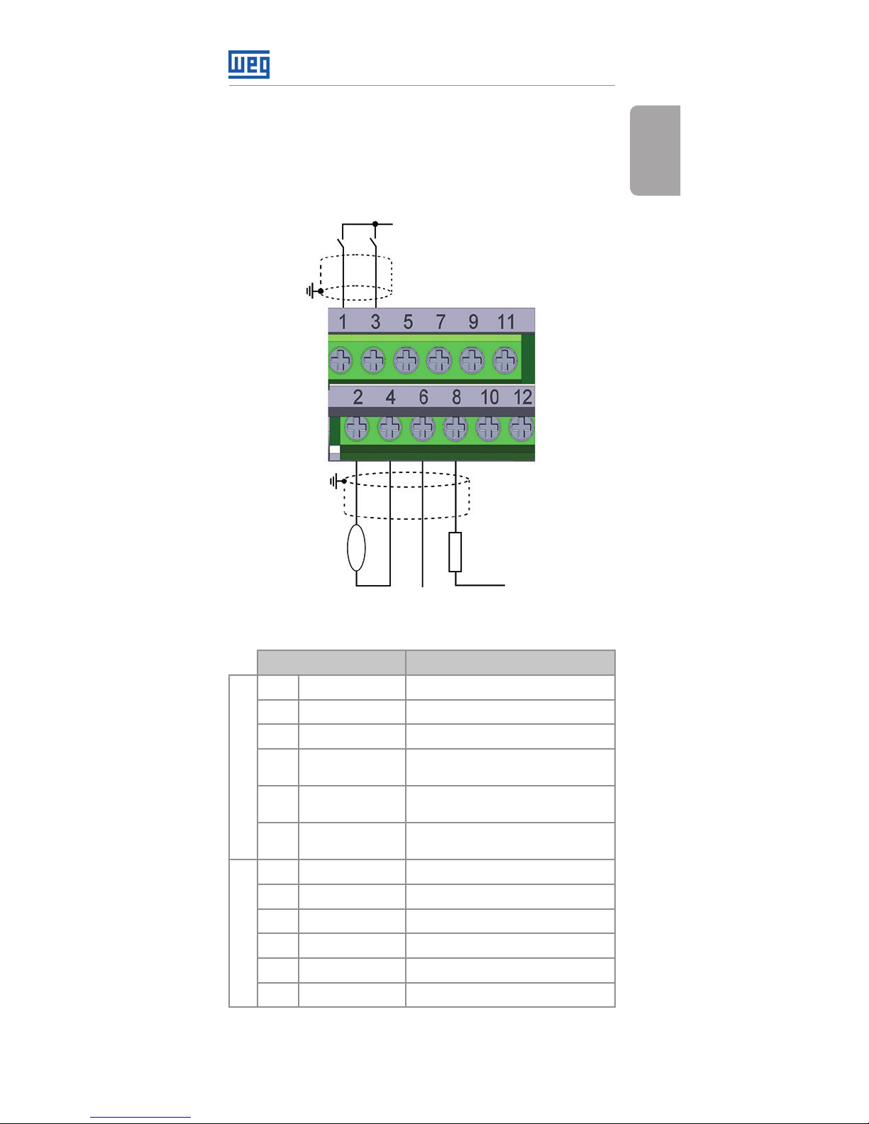
5 CONFIGURATIONS
The control connections must be done as shown in
figure 1.
DI1
DI2
GND
DO1-RL-NO
RS485 - B
+24 V
DO1-RL-C
RS485 - A
DO1-RL-NC
GND
AO1
AI1
DO 2-TR
R
rpm
+24 V
Connector Description
Superior Terminal
1 DI1 Digital Input1
3 DI2 Digital Input 2
5 +24 V Power supply +24 Vdc
7 DO1-RL-NO
Digital output 1
(relay NO contact 1)
9 DO1-RL-C
Digital output 1
(relay common point 1)
11 DO1-RL-NC
Digital output 1
(relay NC contact 1)
Inferior Terminal
2 AO1 Analog output 1
4 GND Reference 0 V
6 AI1 Analog Input 1
8 DO2-TR Digital output 2 (transistor)
10 RS485 - B RS485 (terminal B)
12 RS485 - A RS485 (terminal A)
Figure 1: Signals of the control connector

RS232 Communication Plug-in Module
English
8 | CFW500
The location of the DIP-switches used to select the
type of analog input and output signal and termination
of RS485 network can be better viewed in figure A.2. In
order to use the analog input and/or output with signal
in current, the switch S1 and related parameters must be
adjusted according to table 1. For further details on the
control connections refer to chapter 3 - Installation and
Connection of the CFW500 user’s manual.
Table 1: Switch configurations to select the analog input
and output signal type in the CFW500-CRS232
Input/
Output
Signal
Setting of
SwitchS1
Signal
Range
Parameter
Setting
AI1
Voltage S1.1 = OFF 0...10 V P0233 = 0 or 2
Current S1.1 = ON
0...20 mA P0233 = 0 or 2
4...20 mA P0233 = 1 or 3
AO1
Voltage S1.2 = ON 0...10 V P0253 = 0 or 3
Current S1.2 = OFF
0...20 mA P0253 = 1 or 4
4...20 mA P0253 = 2 or 5
Table 2: Switch configurations to configure RS485 and
RS232 in the CRS232
Communications Switch
Settings of
the Keys
Option
RS485 S1
(*)
S1.3 = OFF and
S1.4 = OFF
RS485
Termination OFF
S1.3 = ON and
S1.4 = ON
RS485
Termination ON
RS232 S2
(*)
S2.1 = OFF and
S2.2 = OFF
RS232 in normal
communication
mode
S2.1 = ON and
S2.2 = ON
RS232 in firmware
programing
mode
(*) Any other combination of the switches is not allowed.
RS232 Communication Plug-in Module
English
CFW500 | 9
The RS232 plug-in module presents the following
features:
Parameterization, command and monitoring of
the inverter by SuperDrive G2 e WLP application
software (available in CFW500 CD-ROM).
CFW500 firmware programming/atualization by FDT
application software (available in CFW500 CD-ROM).
ATTENTION!
With switches S2.1=ON and S2.2=ON the
inverter stays in the firmware programing
state. This operation must only be executed
under WEG’s orientation. Improper use of
this application may damage the equipment.
This module has a connector (figure A.2) to enable the
use of the CFW500-MMF Flash Memory Module , which
allows data transfer between inverters. For further details
on this accessory, refer to the installation and operation
guide of the CFW500-MMF.
NOTE!
When connecting to the PC, the associated
serial port is automatically determined by
the operating system some seconds after
the connection. The user can easily identify
or change the associated COM port in:
Control Panel → System → Hardware →
Device Manager → COM & LPT Ports.
For further details, refer to the installation
manual available in the CD-ROM.
 Loading...