

Page 1
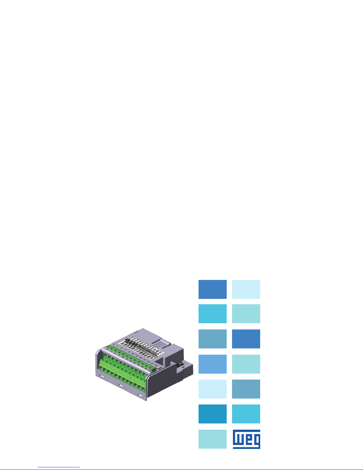
IOR Plug-in Module
Módulo Plug-in de
Expansión IOR
Módulo Plug-in de
Expansão IOR
CFW500
Installation, Configuration and Operation Guide
Guía de Instalación, Configuración y Operación
Guia de Instalação, Configuração e Operação
Motors | Automation | Energy | Transmission & Distribution | Coatings
Page 2

Page 3

Summary / Índice
English
EspañolPortuguês
SUMMARY
1 SAFETY INFORMATION ...............................5
1.1 SAFETY WARNINGS ...................................5
1.2 PRELIMINARY RECOMMENDATIONS .......5
2 GENERAL INFORMATION ...........................5
3 CONTENTS OF THE PACKAGE ..................6
4 ACCESSORY INSTALLATION ....................6
5 SETTINGS ...................................................... 7
APPENDIX A – FIGURES ...............................20
ÍNDICE
1 INFORMACIONES DE SEGURIDAD .........10
1.1 AVISOS DE SEGURIDAD ............................ 10
1.2 RECOMENDACIONES PRELIMINARES ... 10
2 INFORMACIONES GENERALES ..............10
3 CONTENIDO DEL EMBALAJE .................11
4 INSTALACIÓN DEL ACCESORIO ............11
5 CONFIGURACIONES ..................................12
ANEXO A – FIGURAS .....................................20
ÍNDICE
1 INFORMAÇÕES DE SEGURANÇA ............15
1.1 AVISOS DE SEGURANÇA ......................... 15
1.2 RECOMENDAÇÕES PRELIMINARES ....... 15
2 INFORMAÇÕES GERAIS ...........................15
3 CONTEÚDO DA EMBALAGEM ..................16
4 INSTALAÇÃO DO ACESSÓRIO ................16
5 CONFIGURAÇÕES .....................................17
ANEXO A – FIGURAS .....................................20
Page 4

Page 5
IOR Plug-in Module
English
CFW500 | 5
1 SAFETY INFORMATION
1.1 SAFETY WARNINGS
NOTE!
Only use the expansion plug-in module
for analog, digital and relay inputs and
outputs (CFW500-IOR) on WEG inverters
of the CFW500 line.
We recommend reading the CFW500
user’s manual before installing or
operating this accessory.
This guide contains important information
for the correct understanding and proper
operation of this module.
1.2 PRELIMINARY RECOMMENDATIONS
ATTENTION!
Always disconnect the general power
supply before connecting or disconnecting
the accessories of the frequency inverter
CFW500.
Wait for at least 10 minutes to guarantee
complete de-energization of the inverter.
2 GENERAL INFORMATION
This guide provides instructions for the installation,
configuration and operation of the plug-in expansion
module for digital relay outputs (CFW500-IOR).
Page 6

IOR Plug-in Module
English
6 | CFW500
3 CONTENTS OF THE PACKAGE
When receiving the product, check if this package
contains:
Accessory in anti-static packaging.
Installation, configuration and operation guide.
4 ACCESSORY INSTALLATION
The accessory is easily installed or replaced. For correct
installation of the accessory execute the following steps:
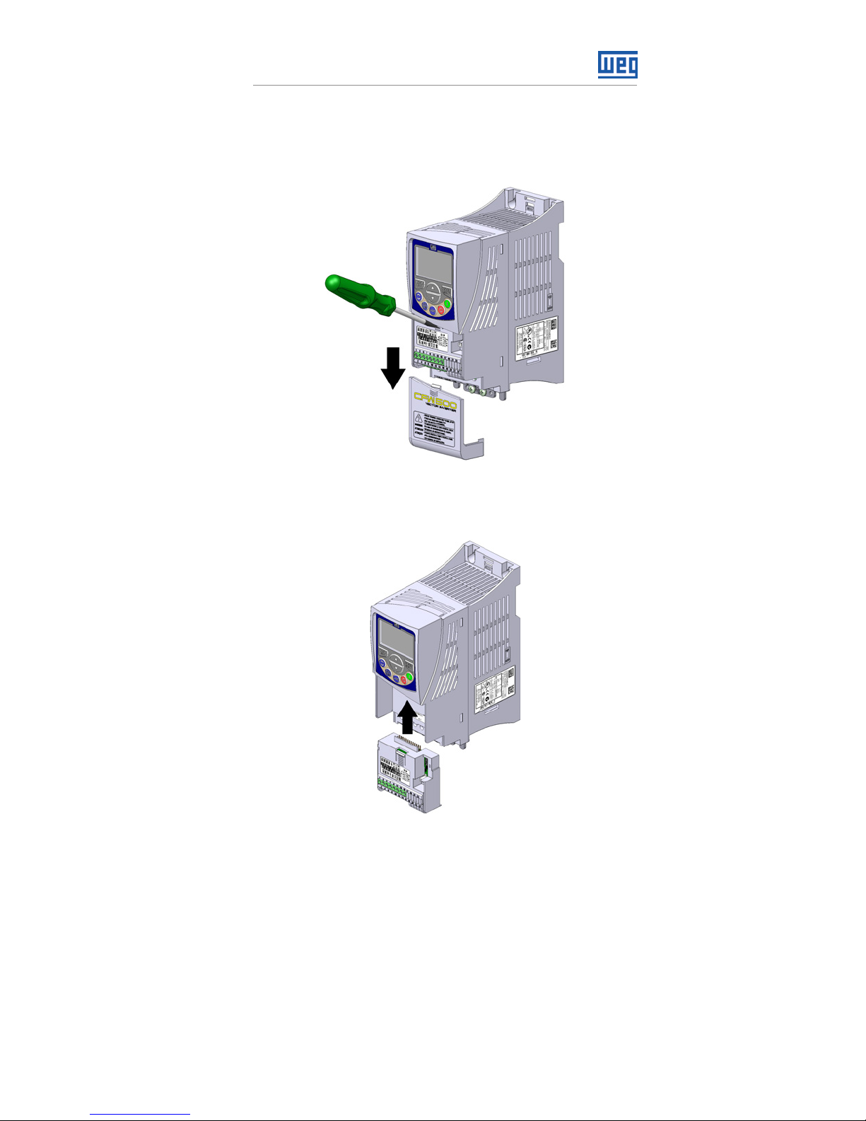
Step 1: With the inverter de-energized, remove the front
cover of the Inverter (figure A.1 (a)).
Step 2: Remove the accessory (connected plug-in
module) if any, as in figure A.1 (a).
Step 3: Fit and press the accessory to be installed as
indicated in figure A.1 (b) and then assemble the front
cover of the inverter.
Step 4: Power up the inverter and check if parameter
P0027 shows value 4 (P0027 = 4). If this information
is not true, check if the module used is actually the
CFW500-IOR500 and repeat steps 1-4.
Page 7
IOR Plug-in Module
English
CFW500 | 7
5 SETTINGS
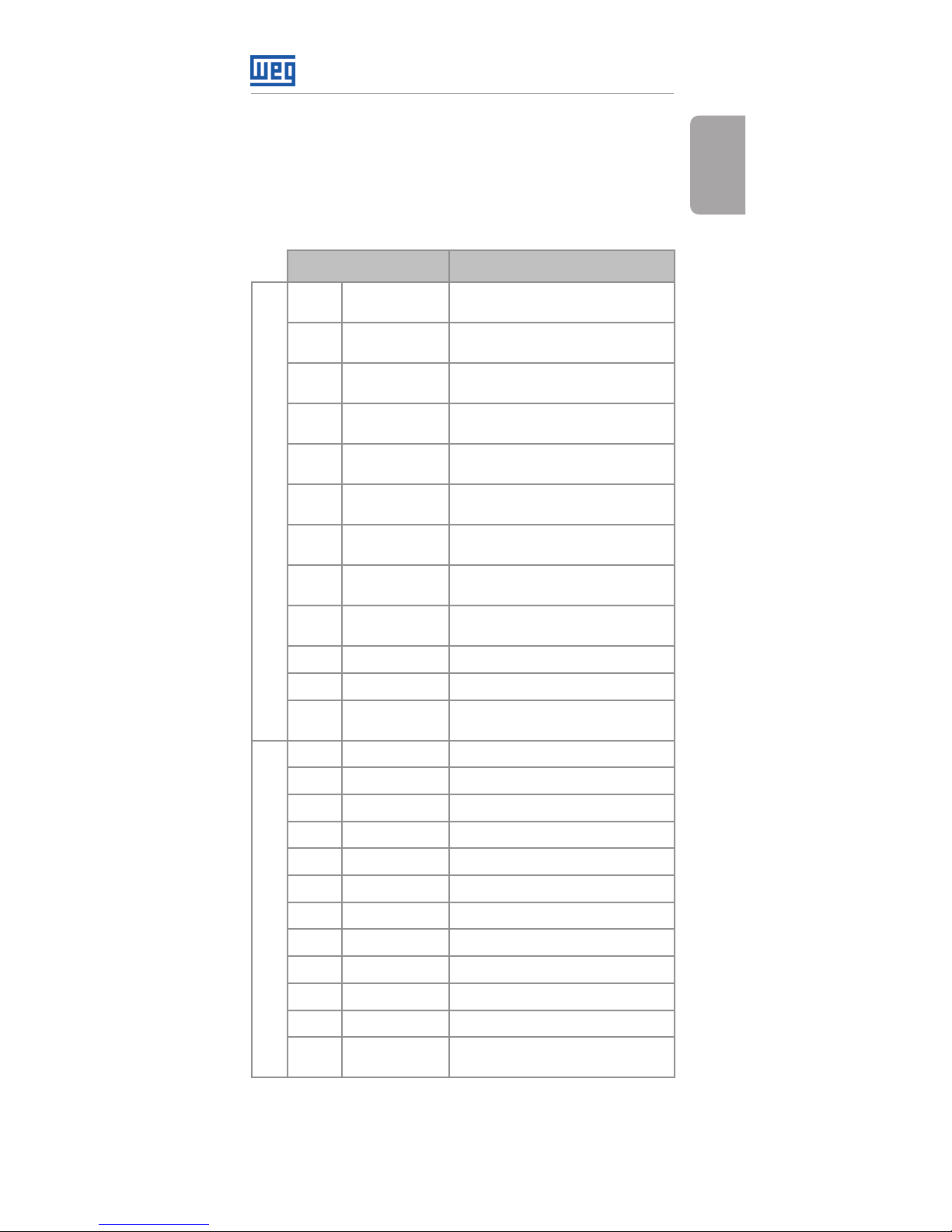
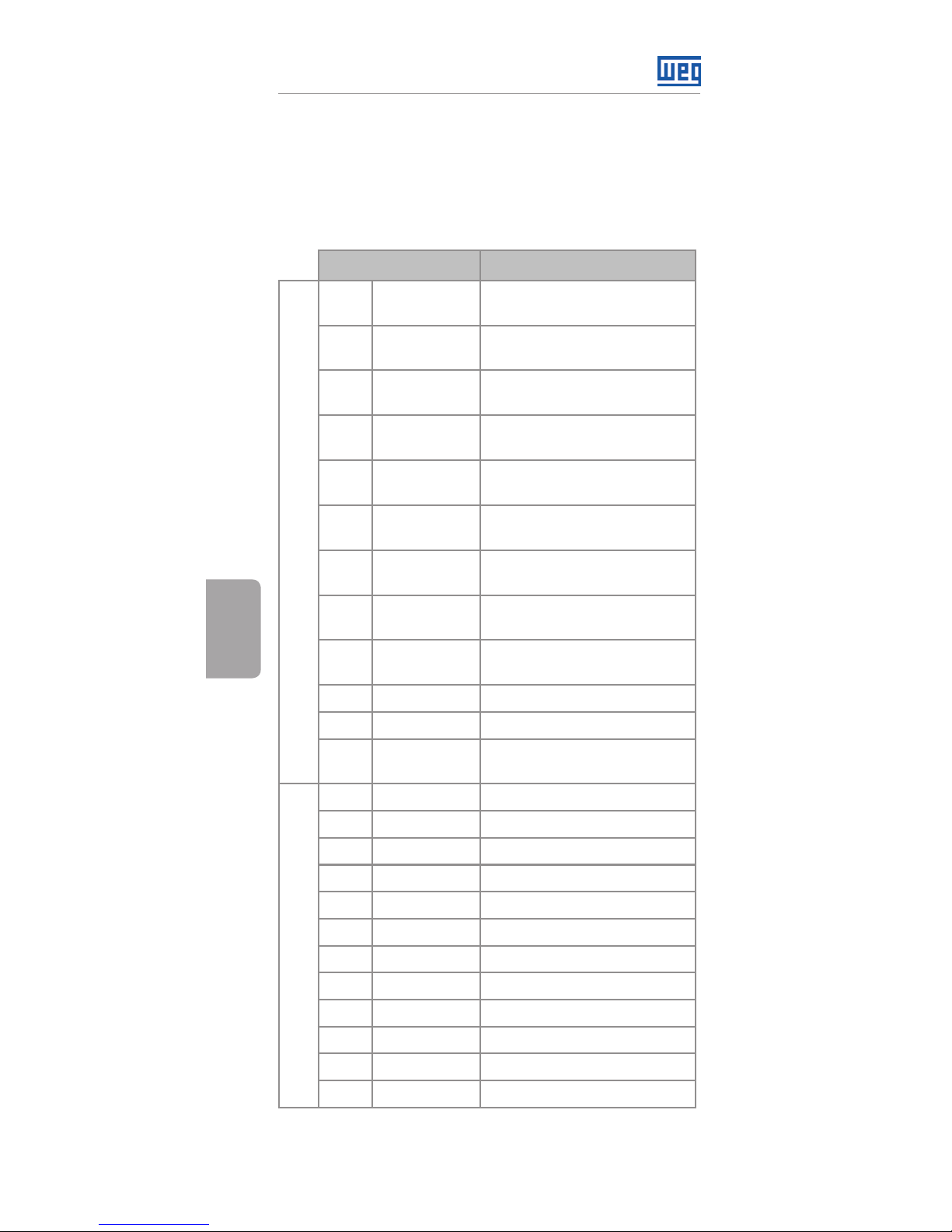
The control connections (analogical input / output, digital
inputs / outputs and RS485 interface) must be performed
as shown in figure 2.
Connector Description
Superior Terminal
1 DO1-NO
Digital output 1
(NO contact of relay 1)
3 DO1-C
Digital output 1
(common point of relay 1)
5 DO1-NC
Digital output 1
(NC contact of relay 1)
7 D03-NO
Digital output 3
(NO contact of relay 3)
9 DO3-C
Digital output 3
(common point of relay 3)
11 DO4-NO
Digital output 4
(NO contact of relay 4)
13 DO4-C
Digital output 4
(common point of relay 4)
15 DO5-NO
Digital output 5
(NO contact of relay 5)
17 DO5-C
Digital output 5
(common point of relay 5)
19 NC Not connected
21 AI1 Analogical input
23 +10 V
Reference +10 Vdc for
potentiometer
Inferior Terminal
2 DI1 Digital input 1
4 DI2 Digital input 2
6 DI3 Digital input 3
8 DI4 Digital input 4
10 DI5 Digital input 5 (NPN)
12 RS485 - A RS485 (Terminal A)
14 RS485 - B RS485 (Terminal B)
16 GND Reference 0 V
18 GND Reference 0 V
20 AO1 Analogical output 1
22 DO2 Digital output 2 (Transistor)
24 +24 V
+24 Vdc Power suply
(Transistor)
Figure 1: Signals of control connector
Page 8
IOR Plug-in Module
English
8 | CFW500
DO5-RL-NO
GND
GND
AO1
DO 2-TR
DI1
DI2
DI3
DI4
DI5
DO5-RL-C
NC
GND
AI1
+10 V
+24 V
rpm
R
≥5 kΩ
DO1-RL-NC
DO4-RL-C
RS485 - B
DO3-RL-C
DO1-RL-C
DO4-RL-NO
RS485 - A
DO3-RL-NO
DO1-RL-NO
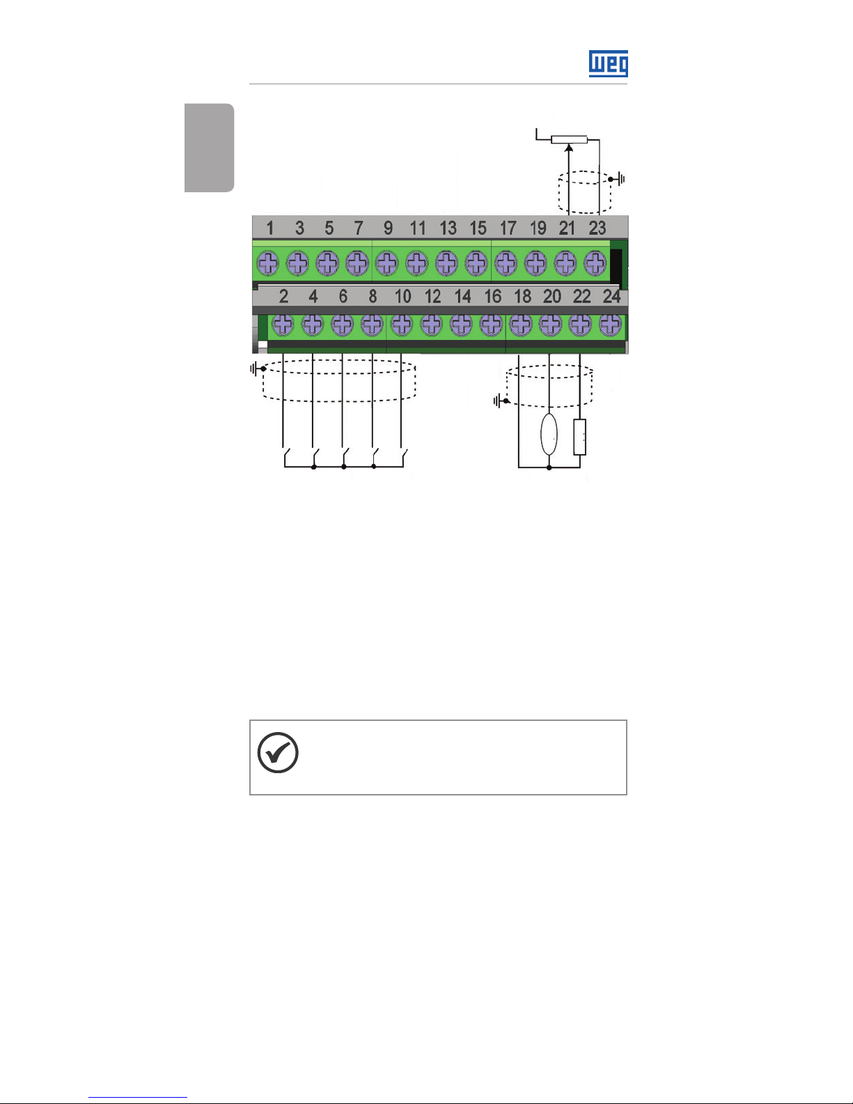
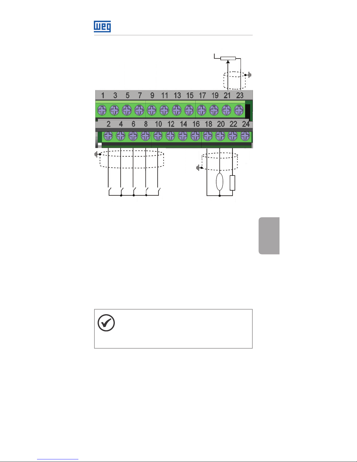
Figure 2: Control connections
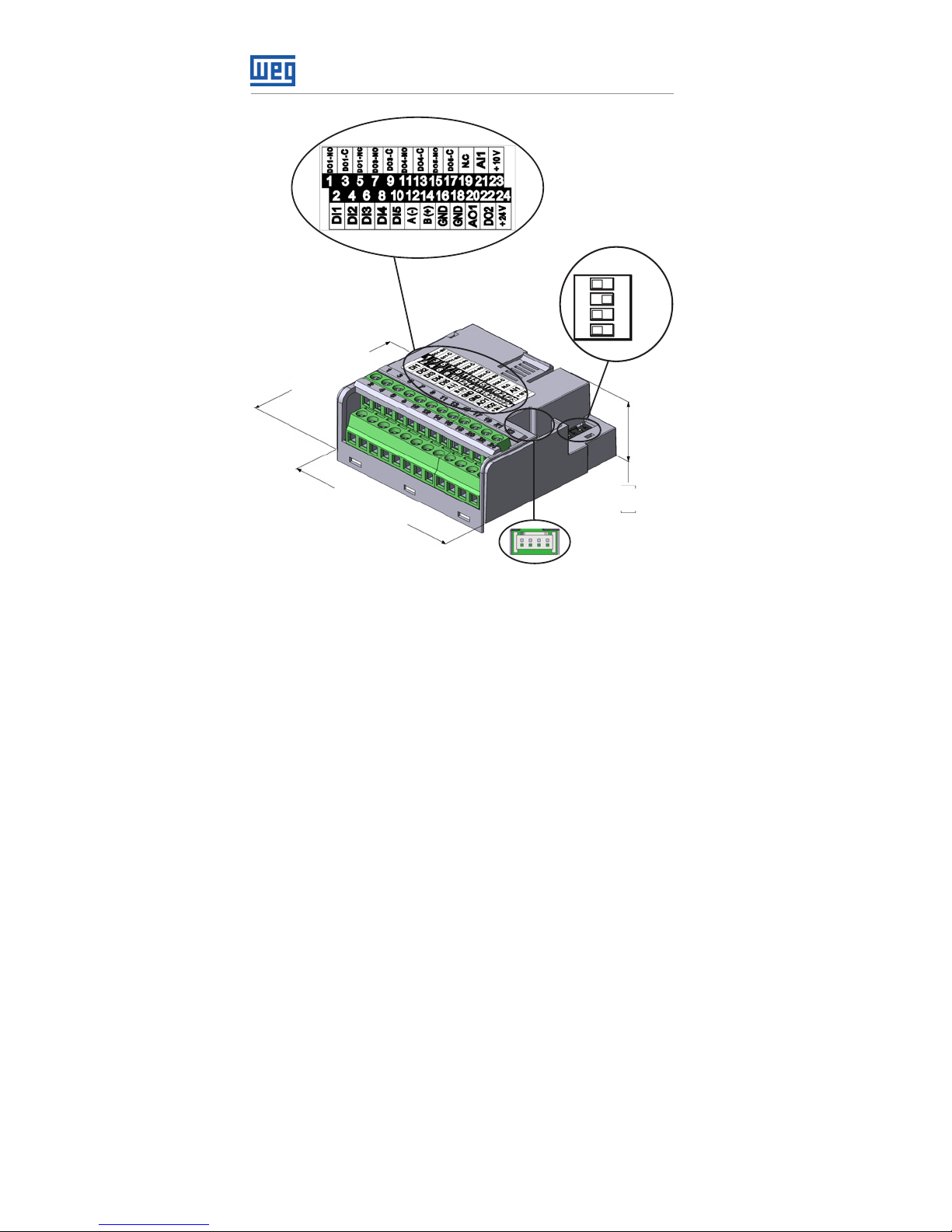
The location of the DIP switches to select the kind of
analog output and input signal can be better viewed in
figure A.2. To use the analog inputs and/ or outputs with
signal in current, switch S1 and related parameters must
be set as indicated in table 1. For further details about
the control connections see chapter 3 - Installation and
Connection of the CFW500 user's manual.
NOTE!
The digital input signal DI5 is allways NPN
input instead of P0271 configuration.
Page 9
IOR Plug-in Module
English
CFW500 | 9
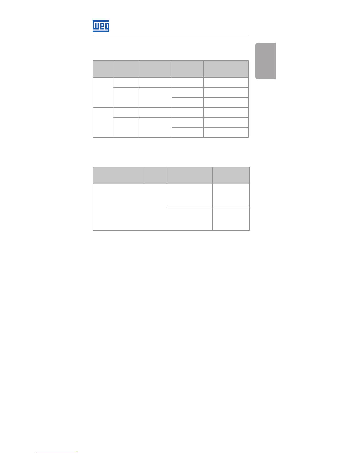
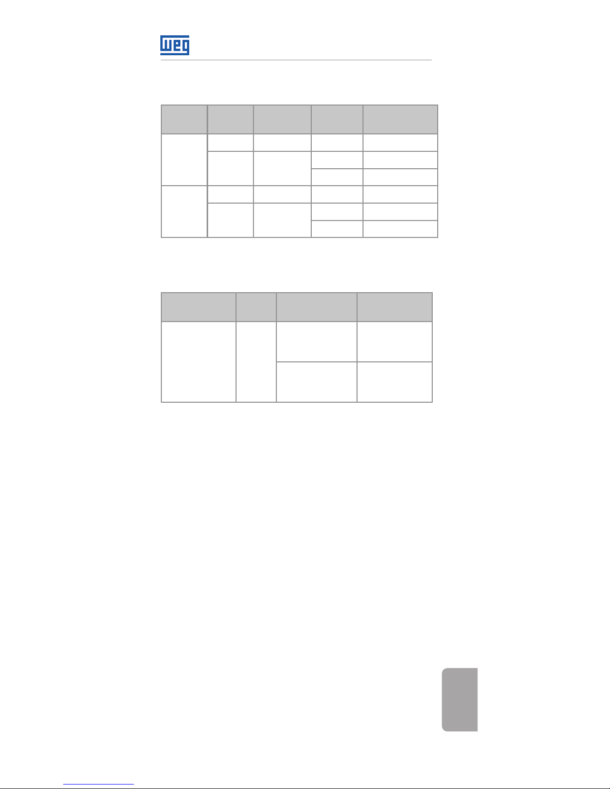
Table 1: Settings of switches to select the type of analog
input and output signal
Input/
Output
Signal
Setting of
Switch S1
Range of
Signal
Parameter
Settings
AI1
Voltage S1.1 = OFF 0...10 V P0233 = 0 or 2
Current S1.1 = ON
0...20 mA P0233 = 0 or 2
4...20 mA P0233 = 1 or 3
AO1
Voltage S1.2 = ON 0...10 V P0253 = 0 or 3
Current S1.2 = OFF
0...20 mA P0253 = 1 or 4
4...20 mA P0253 = 2 or 5
Table 2: Configurations of the RS485 configuration
switches
Communication Switch
Switch
Setting
Option
RS485 S1
(*)
S1.3 = OFF and
S1.4 = OFF
RS485
termination
OFF
S1.3 = ON and
S1.4 = ON
RS485
termination
ON
(*) No other combinations of the switches are allowed.
This module has a connector (figure A.2) to enable the
use of the Flash Memory Module (CFW500-MMF), which
allows data transfer between inverters. For further details
on this accessory, refer to the installation, configuration
and operation guide of the CFW500-MMF.
Page 10
Módulo Plug-in de Expansión IOR
10 | CFW500
Español
1 INFORMACIONES DE SEGURIDAD
1.1 AVISOS DE SEGURIDAD
¡NOTA!
Solamente utilizar el módulo plug-in de
expansión de entradas y salidas (I/Os)
analógicas, digitales y a relés (CFW500-IOR)
en los convertidores WEG línea CFW500.
Se recomienda la lectura del manual del
usuario del CFW500 antes de instalar u
operar este accesorio.
El contenido de esta guía fornece
informaciones importantes para el correcto
entendimiento y buen funcionamento de
este módulo.
1.2 RECOMENDACIONES PRELIMINARES
¡ATENCIÓN!
Siempre desconecte la alimentación
general antes de conectar o desconectar
los accesorios del convertidor de
frecuencia CFW500.
Aguarde por lo menos 10 minutos para
garantizar la desenergización completa
del convertidor.
2 INFORMACIONES GENERALES
Esta guía orienta en la instalación, configuración y
operación del módulo plug-in de expansión de salidas
digitales con relés (CFW500-IOR).
Page 11

Módulo Plug-in de Expansión IOR
CFW500 | 11
Español
3 CONTENIDO DEL EMBALAJE
Al recibir el producto, verifique si el embalaje contiene:
Accesorio en embalaje antiestático.
Guía de instalación, configuración y operación.
4 INSTALACIÓN DEL ACCESORIO
El accesorio es fácilmente instalado o sustituido. Para
la correcta instalación del accesorio, ejecute los pasos
a seguir:
Paso 1: Con el convertidor desenergizado, retire la tapa
frontal del mismo (figura A.1 (a)).
Paso 2: Retire, si existe, el accesorio (módulo plug-in
conectado) conforme la figura A.1 (a).
Paso 3: Encaje y presione el accesorio a ser instalado
conforme indicado en la figura A.1 (b) y después conecte
la tapa frontal del convertidor.
Paso 4: Energice el convertidor y verifique si el
parámetro P0027 indica el valor 4 (P0027=4). En caso
de que esa información no sea verdadera, verifique si
el módulo utilizado realmente es el CFW500-CRS485 y
repita los pasos 1-4.
Page 12
Módulo Plug-in de Expansión IOR
12 | CFW500
Español
5 CONFIGURACIONES
Las conexiones de control (entrada/salida analógica,
entradas/salidas digitales e interfaz RS485) deben ser
hechas en el conector conforme figura 2.
Conector Descripción
Borne Superior
1 DO1-NO
Salida digital 1
(contacto NA del relé 1)
3 DO1-C
Salida digital 1
(punto común del relé 1)
5 DO1-NC
Salida digital 1
(contacto NF del relé 1)
7 D03-NO
Salida digital 3
(contacto NA del relé 3)
9 DO3-C
Salida digital 3
(punto común del relé 3)
11 DO4-NO
Salida digital 4
(contacto NA del relé 4)
13 DO4-C
Salida digital 4
(punto común del relé 4)
15 DO5-NO
Salida digital 5
(contacto NA del relé 5)
17 DO5-C
Salida digital 5
(contacto NA del relé 5)
19 NC No conectado
21 AI1 Entrada analógica
23 +10V
Referencia +10 Vcc para
potenciómetro
Borne Inferior
2 DI1 Entrada digital 1
4 DI2 Entrada digital 2
6 DI3 Entrada digital 3
8 DI4 Entrada digital 4
10 DI5 Entrada digital 5 (NPN)
12 RS485 - A RS485 (Terminal A)
14 RS485 - B RS485 (Terminal B)
16 GND Referencia 0 V
18 GND Referencia 0 V
20 AO1 Salida analógica 1
22 DO2 Salida digital 2 (Transistor)
24 +24V Fuente +24 Vcc (Transistor)
Figura 1: Señales del conector de control
Page 13
Módulo Plug-in de Expansión IOR
CFW500 | 13
Español
DO5-RL-NO
GND
GND
AO1
DO 2-TR
DI1
DI2
DI3
DI4
DI5
DO5-RL-C
NC
GND
AI1
+10 V
+24 V
rpm
R
≥5 kΩ
DO1-RL-NC
DO4-RL-C
RS485 - B
DO3-RL-C
DO1-RL-C
DO4-RL-NO
RS485 - A
DO3-RL-NO
DO1-RL-NO
Figura 2: Conexiones de control
La localización de las DIP-switches para selección del
tipo de señal de la entrada y salida analógica puede
ser mejor visualizada en la figura A.2. Para utilizar las
entradas y/u salidas analógicas con señal en corriente,
se debe ajustar la llave S1 y los parámetros relacionados
conforme tabla 1. Para más detalles sobre las
conexiones de control consulte el capítulo 3 - Instalación
y Conexion del manual del usuario del CFW500.
¡NOTA!
La señal de la entrada digital DI5 es siempre
NPN, independientemente de la configuración
en P0271.
Page 14
Módulo Plug-in de Expansión IOR
14 | CFW500
Español
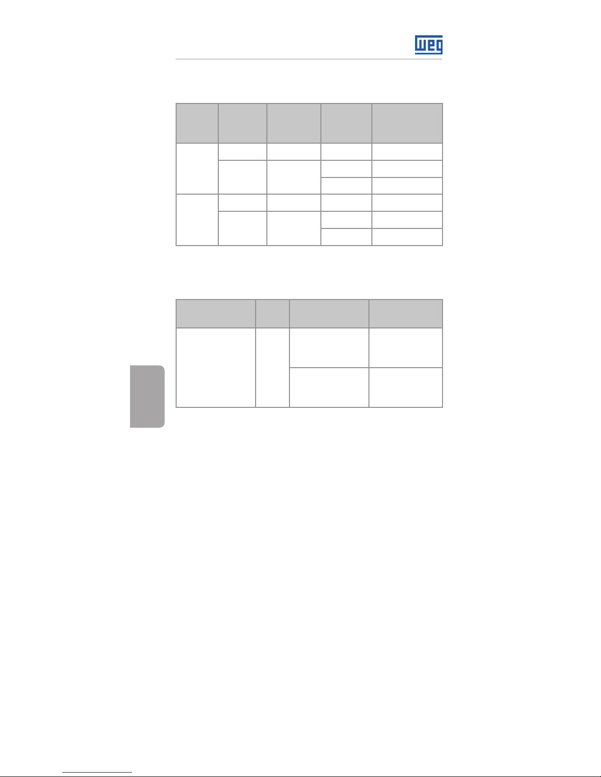
Tabla 1: Configuraciones de las llaves para selección del
tipo de señal en la entrada y salida analógica
Entrada/
Salida
Señal
Ajuste de la
Llave S1
Rango de
la Señal
Ajuste de
Parámetros
AI1
Tensión S1.1 = OFF 0...10 V P0233 = 0 o 2
Corriente S1.1 = ON
0...20 mA P0233 = 0 o 2
4...20 mA P0233 = 1 o 3
AO1
Tensión S1.2 = ON 0...10 V P0253 = 0 o 3
Corriente
S1.2 =
OFF
0...20 mA P0253 = 1 o 4
4...20 mA P0253 = 2 o 5
Tabla 2: Configuraciones de las llaves para configuración
de la RS485
Comunicación Llave
Ajuste de las
Llaves
Opción
RS485 S1
(*)
S1.3 = OFF y
S1.4 = OFF
Terminación
RS485
apagada
S1.3 = ON y
S1.4 = ON
Terminación
RS485
encendida
(*) Cualquier otra combinación de las llaves no está permitida.
Este módulo posee un conector (figura A.2) para utilización
del Módulo de Memória Flash (CFW500-MMF), el cual
permite la transferencia de datos entre los convertidores.
Para más detalles sobre este accesorio consulte la
guía de instalación, configuración y operación del
CFW500-MMF.
Page 15
Módulo Plug-in de Expansão IOR
CFW500 | 15
Português
1 INFORMAÇÕES DE SEGURANÇA
1.1 AVISOS DE SEGURANÇA
NOTA!
Somente utilizar o módulo plug-in de
expansão de entradas e saídas (I/Os)
analógicas, digitais e a relés (CFW500-IOR)
nos inversores WEG linha CFW500.
Recomenda-se a leitura do manual do
usuário do CFW500 antes de instalar ou
operar esse acessório.
O conteúdo deste guia fornece
informações importantes para o correto
entendimento e bom funcionamento
deste módulo.
1.2 RECOMENDAÇÕES PRELIMINARES
ATENÇÃO!
Sempre desconecte a alimentação geral
antes de conectar ou desconectar os
acessórios do inversor de frequência
CFW500.
Aguarde pelo menos 10 minutos para
garantir a desenergização completa do
inversor.
2 INFORMAÇÕES GERAIS
Este guia orienta na instalação, configuração e operação
do módulo plug-in de expansão de saídas digitais com
relés (CFW500-IOR).
Page 16

Módulo Plug-in de Expansão IOR
16 | CFW500
Português
3 CONTEÚDO DA EMBALAGEM
Ao receber o produto, verificar se a embalagem contém:
Acessório em embalagem anti-estática.
Guia de instalação, configuração e operação.
4 INSTALAÇÃO DO ACESSÓRIO
O acessório é facilmente instalado ou substituído.
Para a correta instalação do acessório execute os
passos a seguir:
Passo 1: Com o inversor desenergizado, retire a tampa
frontal do Inversor (figura A.1 (a)).
Passo 2: Retire, se houver, o acessório (módulo plug-in
conectado) conforme a figura A.1 (a).
Passo 3: Encaixe e pressione o acessório a ser instalado
conforme indicado na figura A.1 (b) e após conecte a
tampa frontal do inversor.
Passo 4: Energize o inversor e verifique se o parâmetro
P0027 indica o valor 4 (P0027=4). Caso essa informação
não for verdadeira, verifique se o módulo utilizado
realmente é o CFW500-IOR500 e repita os passos 1-4.
Page 17
Módulo Plug-in de Expansão IOR
CFW500 | 17
Português
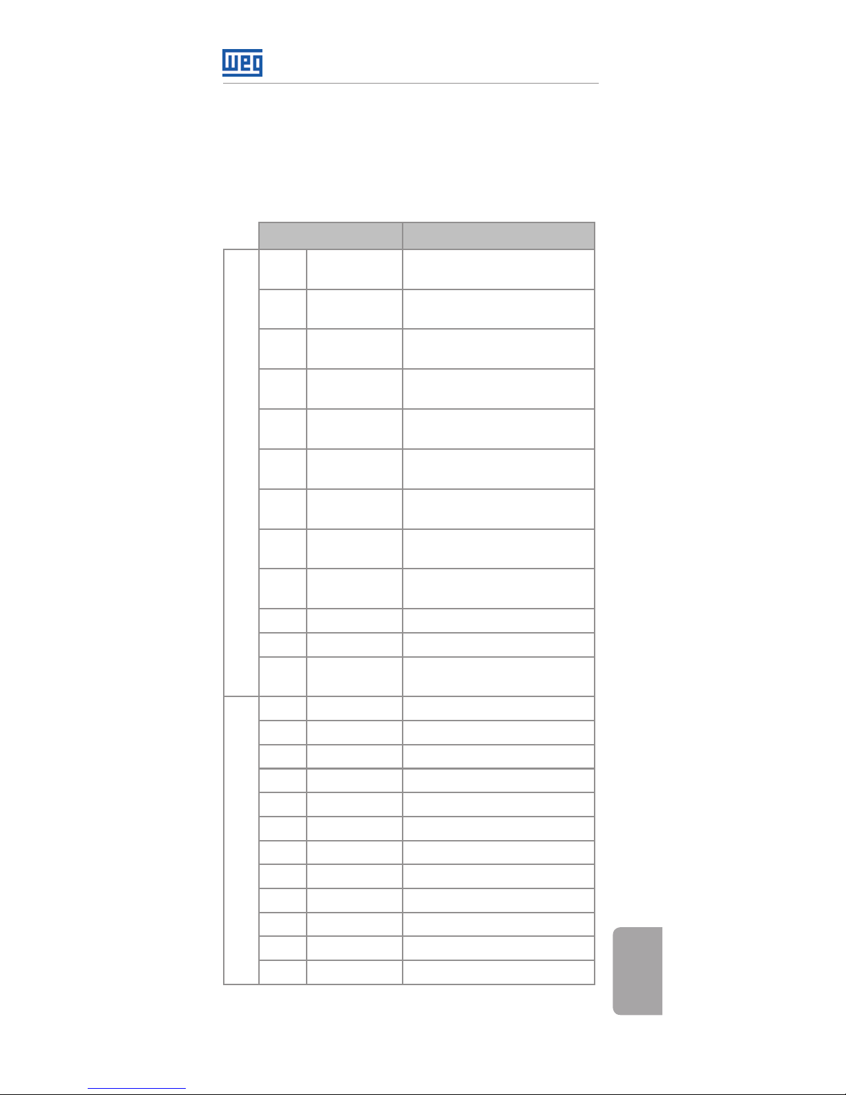
5 CONFIGURAÇÕES
As conexões de controle (entrada/saída analógica,
entradas/saídas digitais e interface RS485) devem ser
feitas no conector conforme figura 2.
Conector Descrição
Borne Superior
1 DO1-NO
Saída Digital 1
(Contato NA do Relé 1)
3 DO1-C
Saída Digital 1
(Ponto comum do Relé 1)
5 DO1-NC
Saída Digital 1
(Contato NF do Relé 1)
7 D03-NO
Saída Digital 3
(Contato NA do Relé 3)
9 DO3-C
Saída Digital 3
(Ponto comum do Relé 3)
11 DO4-NO
Saída Digital 4
(Contato NA do Relé 4)
13 DO4-C
Saída Digital 4
(Ponto comum do Relé 4)
15 DO5-NO
Saída Digital 5
(Contato NA do Relé 5)
17 DO5-C
Saída Digital 5
(Ponto comum do Relé 5)
19 NC Não conectado
21 AI1 Entrada Analógica
23 +10V
Referência +10 Vcc para
Potenciômetro
Borne Inferior
2 DI1 Entrada Digital 1
4 DI2 Entrada Digital 2
6 DI3 Entrada Digital 3
8 DI4 Entrada Digital 4
10 DI5 Entrada Digital 5 (NPN)
12 RS485 - A RS485 (Terminal A)
14 RS485 - B RS485 (Terminal B)
16 GND Referência 0 V
18 GND Referência 0 V
20 AO1 Saída Analógica 1
22 DO2 Saída Digital 2 (Transistor)
24 +24V Fonte +24 Vcc (Transistor)
Figura 1: Sinais do conector de controle
Page 18
Módulo Plug-in de Expansão IOR
18 | CFW500
Português
DO5-RL-NO
GND
GND
AO1
DO 2-TR
DI1
DI2
DI3
DI4
DI5
DO5-RL-C
NC
GND
AI1
+10 V
+24 V
rpm
R
≥5 kΩ
DO1-RL-NC
DO4-RL-C
RS485 - B
DO3-RL-C
DO1-RL-C
DO4-RL-NO
RS485 - A
DO3-RL-NO
DO1-RL-NO
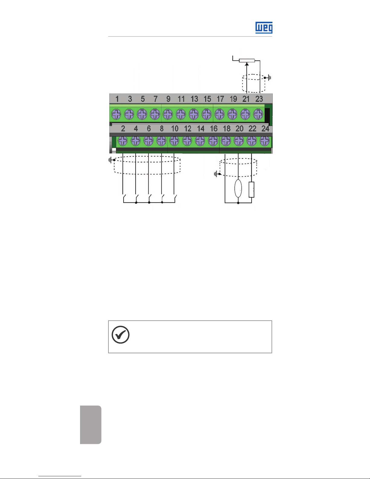
Figura 2: Conexões de controle
A localização das DIP-switches para seleção do tipo de
sinal da entrada e saída analógica podem ser melhor
visualizadas na figura A.2. Para utilizar as entradas e/ou
saídas analógicas com sinal em corrente deve-se ajustar
a chave S1 e os parâmetros relacionados conforme
tabela 1. Para mais detalhes sobre as conexões de
controle consulte o capítulo 3 do manual do usuário
do CFW500.
NOTA!
O sinal da entrada digital DI5 é sempre NPN,
independente da configuração em P0271.
Page 19
Módulo Plug-in de Expansão IOR
CFW500 | 19
Português
Tabela 1: Configurações das chaves parJa seleção do tipo
de sinal na entrada e saída analógica
Entrada/
Saída
Sinal
Ajuste da
Chave S1
Faixa do
Sinal
Ajuste de
Parâmetros
AI1
Tensão S1.1 = OFF 0...10 V P0233 = 0 ou 2
Corrente S1.1 = ON
0...20 mA P0233 = 0 ou 2
4...20 mA P0233 = 1 ou 3
AO1
Tensão S1.2 = ON 0...10 V P0253 = 0 ou 3
Corrente S1.2 = OFF
0...20 mA P0253 = 1 ou 4
4...20 mA P0253 = 2 ou 5
Tabela 2: Configurações das chaves para configuração
da RS485
Comunicação Chave
Ajuste das
Chaves
Opção
RS485 S1
(*)
S1.3 = OFF e
S1.4 = OFF
Terminação
RS485
desligada
S1.3 = ON e
S1.4 = ON
Terminação
RS485
ligada
(*) Qualquer outra combinação das chaves não é permitida.
Este módulo possui um conector (figura A.2) para
utilização do Módulo de Memória Flash (CFW500-MMF),
o qual permite a transferência de dados entre inversores.
Para mais detalhes sobre esse acessório consulte
o guia de instalação, configuração e operação do
CFW500-MMF.
Page 20
Appendix A - Anexo A
20 | CFW500
APPENDIX A – FIGURES
ANEXO A – FIGURAS
(a) Removal of front cover and accessory
(a) Remoción de la tapa frontal y del accesorio
(a) Remoção da tampa frontal e de acessório
(b) Accessory connection
(b) Conexión del accesorio
(b) Conexão de acessório
Figure A.1 (a) to (b): Installation of accessory
Figura A.1 (a) a (b): Instalación de accesorio
Figura A.1 (a) a (b): Instalação de acessório
Page 21
Appendix A - Anexo A
CFW500 | 21
68.5
[2.7]
22.6
0.9
[2.4]
61.2
S1
1
2
3 4
AI1
AO1
B(+)
A(-)
ON
Figure A.2: IOR500 dimensions in mm [in], DIP-switches
location and MCard connector
Figura A.2: Dimensiones del IOR500 en mm [in],
localización de las DIP-switches y conectador de MCard
Figura A.2: Dimensões do IOR500 em mm [in], localização
das DIP-switches e conector
Page 22

NOTES / NOTAS / ANOTAÇÕES
Page 23

Page 24

Document: 10002046570 / 02
1177103 6
WEG Drives & Controls - Automação LTDA.
Jaraguá do Sul - SC - Brazil
Phone 55 (47) 3276-4000 - Fax 55 (47) 3276-4020
São Paulo - SP - Brazil
Phone 55 (11) 5053-2300 - Fax 55 (11) 5052-4212
[email protected]
www.weg.net
 Loading...