

Page 1

Serial Remote HMI
HMI Remota Serial
HMI Remota Serial
CFW500
Installation, Configuration and Operation Guide
Guía de Instalación, Configuración y Operación
Guia de Instalação, Configuração e Operação
Motors | Automation | Energy | Transmission & Distribution | Coatings
Page 2

Page 3

Summary / Índice
English
EspañolPortuguês
SUMMARY
1 SAFETY INFORMATION ...............................5
1.1 SAFETY WARNINGS ..................................5
1.2 PRELIMINARY RECOMMENDATIONS .......5
2 GENERAL INFORMATION ...........................5
3 PACKAGE CONTENT ...................................5
4 ACCESSORY INSTALLATION .....................6
5 CONFIGURATIONS .......................................6
APPENDIX A – FIGURES ...............................17
ÍNDICE
1 INFORMACIONES DE SEGURIDAD ...........9
1.1 AVISOS DE SEGURIADAD ..........................9
1.2 RECOMENDACIONES PRELIMINARES ..... 9
2 INFORMACIONES GENERALES ................. 9
3 CONTENIDO DEL EMBALAJE ....................9
4 INSTALACIÓN DEL ACCESORIO..............10
5 CONFIGURACIONES ..................................10
ANEXO A – FIGURAS .....................................17
ÍNDICE
1 INFORMAÇÕES DE SEGURANÇA ............13
1.1 AVISOS DE SEGURANÇA .......................... 13
1.2 RECOMENDAÇÕES PRELIMINARES ....... 13
2 INFORMAÇÕES GERAIS ...........................13
3 CONTEÚDO DA EMBALAGEM ..................13
4 INSTALAÇÃO DO ACESSÓRIO .................14
5 CONFIGURAÇÕES......................................14
ANEXO A – FIGURAS .....................................17
Page 4

Page 5
Serial Remote HMI
English
CFW500 | 5
1 SAFETY INFORMATION
1.1 SAFETY WARNINGS
NOTE!
This guide contains important information
for the correct understanding and proper
operation of the CFW500-HMIR Serial
Remote Human-Machine Interface.
Only use the CFW500-HMIR Serial Remote
Human-Machine Interface in WEG CFW500
inverters only.
We recommend reading the CFW500 user’s
manual before installing or operating this
accessory.
1.2 PRELIMINARY RECOMMENDATIONS
ATTENTION!
Always disconnect the general power
supply before connecting or disconnecting
the accessories of the CFW500 frequency
inverter.
Wait at least 10 minutes to guarantee
complete de-energization of the inverter.
2 GENERAL INFORMATION
This guide shows how to install, configure and operate
the CFW500-HMIR Serial Remote Human-Machine
Interface. This optional allow the mounting of CFW500
human machine interface at the electrial panel door.
3 PACKAGE CONTENT
When receiving the product, check if the package
contains:
Accessory in anti-static package.
Installation, configuration and operation guide.
Page 6

Serial Remote HMI
English
6 | CFW500
4 ACCESSORY INSTALLATION
The accessory is easily installed or replaced. For the
proper installation of the accessory, follow steps below:
Step 1: The CFW500-HMIR can be connected to any
CFW500 plug-in module. With the inverter de-energized,
remove the front cover of the Inverter (Figure A1 on
page 17).
Step 2: Connect the wires of the CFW500-CCHMIRxxM
cable to the RS485 connection on plug-in module
according to the Table 2 on page 7. The Figure A1
on page 17 shows an example with the CFW500-IOS
plug-in module. If you are using a different plug-in module,
refer to its installation, configuration and operation guide
to identify the terminals for the RS485 Serial Connection.
Step 3: Close the inverter front cover.
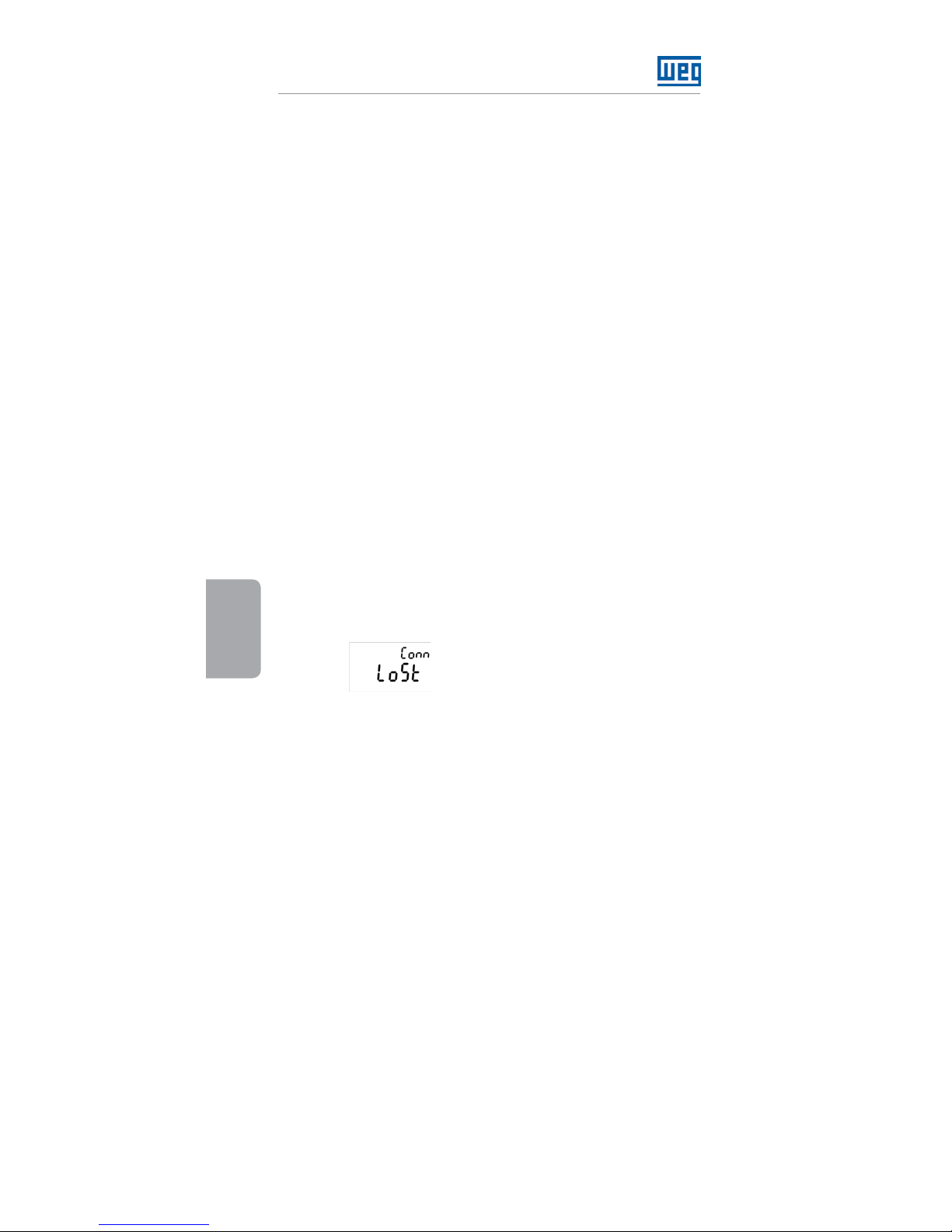
Step 4: Power up the inverter and check if the
CFW500-HMIR as show the following mensage on
the display:
Step 5: Configure the parameter P0312 to HMIR option.
Thus, the Serial Remote HMI will show the same display
data as the inverter local HMI. Otherwise, repeat steps 1-5,
checking the CFW500-CCHMIRxxM cable connections.
5 CONFIGURATIONS
It is mounted externally to the inverters on the panel
door (Figure A2 on page 18) or control desk with a
maximum cable length of 10 m. However, for cables
longer than 10 m, it is necessary an external power
supply of 24 Vdc to power up the Serial Remote HMI.
Protection rate: IP54 / Nema 12.
The CFW500-HMIR works with the CFW500-
CCHMIRxxM cable only. The available lengths are
presented in Table 1 on page 7. For the proper
connection of this cable, check Table 2 on page 7.
Page 7
Serial Remote HMI
English
CFW500 | 7
Table 1: Available lengths for CFW500-CCHMIRxxM cable
Description Name
Length
(m) [in]
WEG
Item
HMI serial cable
CFW500
CFW500-
CCHMIR01M
1 [39.37] 123 30 01 6
HMI serial cable
CFW500
CFW500-
CCHMIR02M
2 [78.74] 12330459
HMI serial cable
CFW500
CFW500-
CCHMIR03M
3 [118.11] 12330460
HMI serial cable
CFW500
CFW500-
CCHMIR05M
5 [196.85] 12330461
HMI serial cable
CFW500
CFW500-
CCHMIR75M
7.5 [295.28] 12330462
HMI serial cable
CFW500
CFW500-
CCHMIR10M
10 [393.70] 12330463
Table 2: CFW500-CCHMIRxxM cable connection
DB9 Connector Color (Wire) Plug-in Module Pin:
2 Blue B (+)
4 Green GND
5 Red +24 V
7 Gray A (-)
Page 8

Serial Remote HMI
English
8 | CFW500
Page 9
HMI Remota Serial
CFW500 | 9
Español
1 INFORMACIONES DE SEGURIDAD
1.1 AVISOS DE SEGURIADAD
¡NOTA!
El contenido de esta guía provee
informaciones importantes para el correcto
entendimiento y buen funcionamiento de la
CFW500-HMIR Interface Hombre-Maquina
Remota Serial.
Solamente utilizar la CFW500-HMIR
Interface Hombre-Maquina Remota Serial
en los convertidores WEG línea CFW500.
Se recomienda la lectura del manual del
usuario del CFW500 antes de instalar o
operar este accesorio.
1.2 RECOMENDACIONES PRELIMINARES
¡ATENCIÓN!
Siempre desconecte la alimentación
general antes de conectar o desconectar
los accesorios de lo convertidor de
frecuencia CFW500.
Aguarde por lo menos 10 minutos para
garantizar la desenergización completa
del convertidor.
2 INFORMACIONES GENERALES
Esta guía orienta en la instalación, configuración y
operación de la CFW500-HMIR Interface HombreMaquina Remota Serial. Este opcional permite la
montage de la inface hombre-maquina del CFW500 en
la puerta del tablero electrico.
3 CONTENIDO DEL EMBALAJE
Al recibir el producto, verifique si el embalaje contiene:
Accesorio en embalaje antiestático.
Guía de instalación, configuración y operación.
Page 10
HMI Remota Serial
10 | CFW500
Español
4 INSTALACIÓN DEL ACCESORIO
El accesorio es fácilmente instalado o sustituido. Para
la correcta instalación del accesorio ejecute los pasos
a seguir:
Paso 1: La CFW500-HMIR puede ser conectada a
cualquier módulo plug-in del convertidor CFW500. Con
el convertidor desenergizado, retire la tapa frontal del
convertidor (Figura A1 en la página 17).
Paso 2: Efectúe la conexión de los alambres (terminales)
del cable CFW500-CCHMIRxxM en la interface RS485
del modulo plug-in conforme Tabla 2 en la página 11.
La Figura A1 en la página 17 muestra un ejemplo
con el módulo plug-in CFW500-IOS. Si está utilizando
un módulo plug-in diferente, verifique en la guía de
instalación, configuración y operación del módulo
plug-in utilizado, los bornes referentes a la conexión de
la interface serial RS485.
Paso 3: Conecte la tapa frontal del convertidor.
Paso 4: Energice el convertidor y verifique si la
CFW500-HMIR presenta la siguiente mensaje en el
display:
Paso 5: Configure el parámetro P0312 para la opcion
HMIR. Con eso, la HMI Remota Serial presentará, en
el display, la misma mensaje de la HMI del convertidor.
En caso contrario, repita los pasos 1-5 verificando las
conexiones del cable CFW500-CCHMIRxxM.
5 CONFIGURACIONES
Es montada externamente a los convertidores en la
puerta del tablero (Figura A2 en la página 18) o mesa
de comando con una longitud de cable máxima de 10
m. Sin embargo, para cables mayores que 10 m es
necesario una fuente externa de 24 Vcc alimentando
la HMI Remota Serial. Grado de protección: IP54 /
Nema 12.
La CFW500-HMIR funciona solamente con el cable
CFW500-CCHMIRxxM. Las longitudes disponibles
son presentadas en la Tabla 1 en la página 11. Para
la correcta conexión de este cable verifique la Tabla
2 en la página 11.
Page 11
HMI Remota Serial
CFW500 | 11
Español
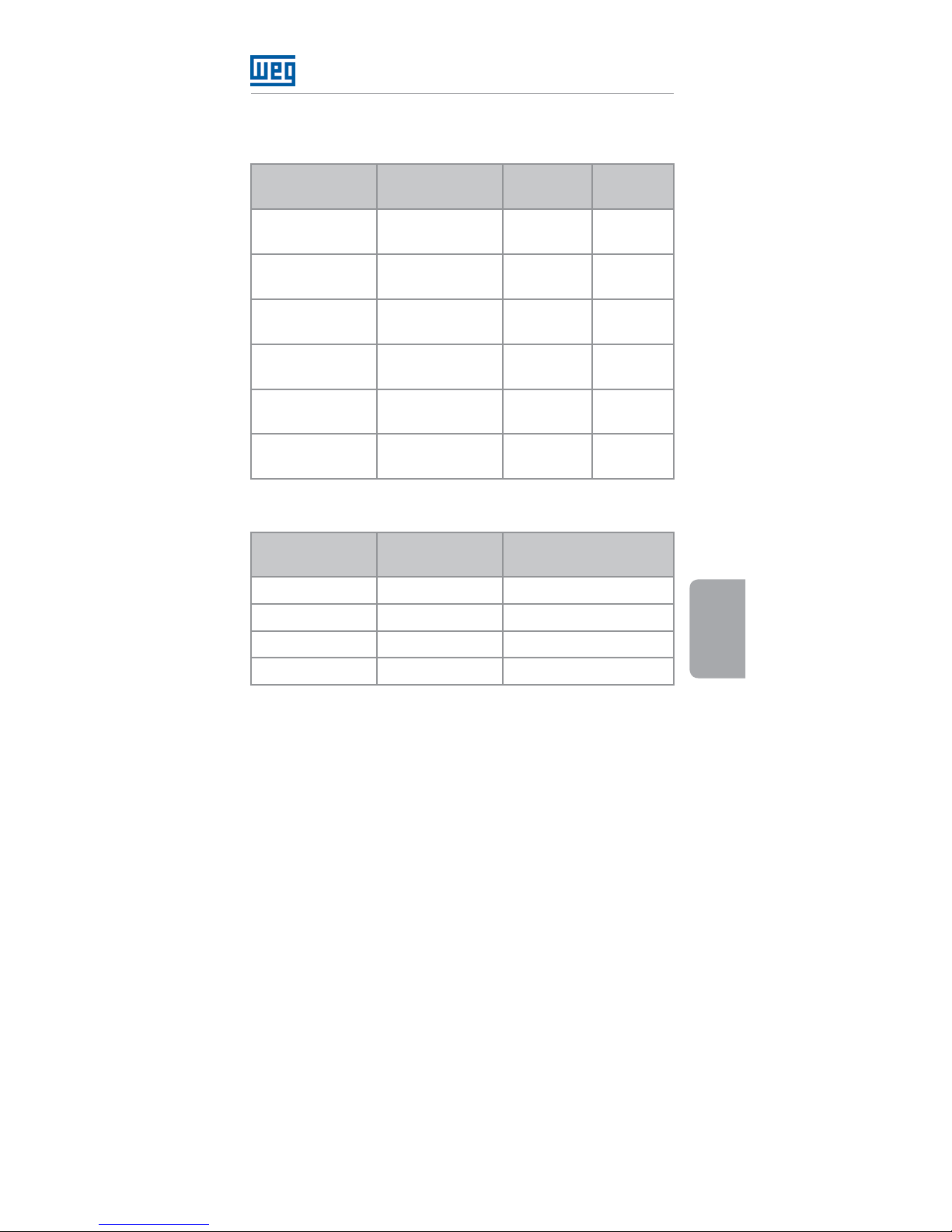
Tabla 1: Longitudes disponibles del cable CFW500-
CCHMIRxxM
Descrición Nombre
Longitud
(m) [in]
Item WEG
Cable de la HMI
serial del CFW500
CFW500-
CCHMIR01M
1 [39,37] 12330016
Cable de la HMI
serial del CFW500
CFW500-
CCHMIR02M
2 [78,74] 12330459
Cable de la HMI
serial del CFW500
CFW500-
CCHMIR03M
3 [118,11] 12330460
Cable de la HMI
serial del CFW500
CFW500-
CCHMIR05M
5 [196,85] 12330461
Cable de la HMI
serial del CFW500
CFW500-
CCHMIR75M
7,5 [295,28] 12330462
Cable de la HMI
serial del CFW500
CFW500-
CCHMIR10M
10 [393,70] 12330463
Tabla 2 : Conexión del cable CFW500-CCHMIRxxM
Perno do
Conector DB9
Color (Alambre)
Perno del Módulo
Plug-in
2 Azul B (+)
4 Verde GND
5 Rojo +24 V
7 Gris A (-)
Page 12

HMI Remota Serial
12 | CFW500
Español
Page 13
HMI Remota Serial
CFW500 | 13
Português
1 INFORMAÇÕES DE SEGURANÇA
1.1 AVISOS DE SEGURANÇA
NOTA!
O conteúdo deste guia fornece informações
importantes para o correto entendimento
e bom funcionamento da CFW500-HMIR
Interface Homem-Máquina Remota Serial.
Somente utilizar a CFW500-HMIR Interface
Homem-Maquina Remota Serial nos
inversores WEG linha CFW500.
Recomenda-se a leitura do manual do
usuário do CFW500 antes de instalar ou
operar esse acessório.
1.2 RECOMENDAÇÕES PRELIMINARES
ATENÇÃO!
Sempre desconecte a alimentação geral
antes de conectar ou desconectar os
acessórios do inversor de frequência
CFW500.
Aguarde pelo menos 10 minutos para
garantir a desenergização completa do
inversor.
2 INFORMAÇÕES GERAIS
Este guia orienta na instalação, configuração e operação
da CFW500-HMIR Interface Homem-Máquina. Este
opcional permite a montagem da interface homemmáquina do CFW500 na porta do painel elétrico.
3 CONTEÚDO DA EMBALAGEM
Ao receber o produto, verificar se a embalagem contém:
Acessório em embalagem anti estática.
Guia de instalação, configuração e operação.
Page 14

HMI Remota Serial
14 | CFW500
Português
4 INSTALAÇÃO DO ACESSÓRIO
O acessório é facilmente instalado ou substituído.
Para a correta instalação do acessório execute os
passos a seguir:
Passo 1: A CFW500-HMIR pode ser conectada a
qualquer módulo plug-in do inversor CFW500. Com o
inversor desenergizado, retire a tampa frontal do Inversor
(Figura A1 na página 17).
Passo 2: Faça a conexão dos terminais do cabo
CFW500-CCHMIRxxM na interface RS485 do
módulo plug-in, conforme Tabela 2 na página 15. A
Figura A1 na página 17 mostra um exemplo com o
módulo plug-in CFW500-IOS. Se estiver utilizando um
módulo plug-in diferente, verifique no guia de instalação,
configuração e operação do módulo plug-in utilizado,
os bornes referentes à conexão da HMI remota serial
CFW500-HMIR (RS485).
Passo 3: Conecte a tampa frontal do inversor.
Passo 4: Energize o inversor e verifique se a CFW500-HMIR
apresenta a seguinte mensagem no display:
Passo 5: Configure o parâmetro P0312 para a opção
HMIR. Com isso, a HMI remota serial CFW500-HMIR
apresentará no display a mesma mensagem da HMI do
inversor. Caso contrário, repita os passos 1-5 verificando
as conexões do cabo CFW500-CCHMIRxxM.
5 CONFIGURAÇÕES
É montada externamente aos inversores na porta
do painel (Figura A2 na página 18) ou mesa de
comando com um comprimento de cabo máximo
de 10 m. Porém, para cabos maiores que 10 m é
necessário uma fonte externa de 24 Vcc alimentando a
HMI remota serial CFW500-HMIR. Grau de proteção:
IP54 / Nema 12.
A CFW500-HMIR funciona somente com o cabo
CFW500-CCHMIRxxM. Os comprimentos
disponíveis são apresentados na Tabela 1 na página
15. Para a correta ligação deste cabo verifique a
Tabela 2 na página 15.
Page 15
HMI Remota Serial
CFW500 | 15
Português
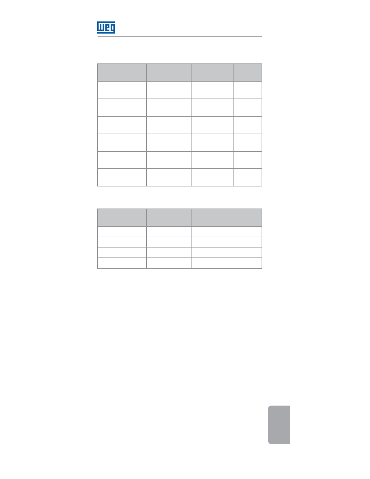
Tabela 1: Comprimentos disponíveis do cabo
CFW500-CCHMIRxxM
Descrição Nome
Comprimento
(m) [in]
Item
WEG
Cabo da HMI
serial do CFW500
CFW500-
CCHMIR01M
1 [39,37] 12330016
Cabo da HMI
serial do CFW500
CFW500-
CCHMIR02M
2 [78,74] 12330459
Cabo da HMI
serial do CFW500
CFW500-
CCHMIR03M
3 [118,11] 12330460
Cabo da HMI
serial do CFW500
CFW500-
CCHMIR05M
5 [196,85] 12330461
Cabo da HMI
serial do CFW500
CFW500-
CCHMIR75M
7,5 [295,28] 12330462
Cabo da HMI
serial do CFW500
CFW500-
CCHMIR10M
10 [393,70] 12330463
Tabela 2: Ligação do cabo CFW500-CCHMIRxxM
Pino do
Conector DB9
Cor (Fio)
Pino do Módulo
Plug-in
2 Azul B (+)
4 Verde GND
5 Vermelho +24 V
7 Cinza A (-)
Page 16

HMI Remota Serial
16 | CFW500
Português
Page 17

Appendix A - Anexo A
CFW500 | 17
APPENDIX A – FIGURES
ANEXO A – FIGURAS
(a) Removal of front cover
(a) Remoción de la tapa frontal
(a) Remoção da tampa frontal
RS485 - A
RS485 - B
GND
+24 V
(b) Accessory connection
(b) Conexión de lo accesorio
(b) Conexão do acessório
Figure A1: (a) to (b) Installation of accessory
Figura A1: (a) a (b) Instalación de lo accesorio
Figura A1: (a) a (b) Instalação do acessório
Page 18

Appendix A - Anexo A
18 | CFW500
69.0 [2.7]
Max. 3.0 [0.1]
19.2 [0.8]
101.0 [4.0]
Figure A2: CFW500-HMIR dimensions in mm [in] and
panel mounting
Figura A2: Dimensiones del CFW500-HMIR en mm [in] y
montaje en tablero
Figura A2: Dimensões do CFW500-HMIR em mm [in] e
montagem em painel
Page 19

Page 20

Document: 10001446141 / 02
11770706
WEG Drives & Controls - Automação LTDA.
Jaraguá do Sul - SC - Brazil
Phone 55 (47) 3276-4000 - Fax 55 (47) 3276-4020
São Paulo - SP - Brazil
Phone 55 (11) 5053-2300 - Fax 55 (11) 5052-4212
[email protected]
www.weg.net
 Loading...