

WEG CFW500-CRS485 Installation, Configuration And Operations Manual
RS485 Communication
Plug-in Module
Módulo Plug-in
Comunicación RS485
Módulo Plug-in
Comunicação RS485
CFW500
Installation, Configuration and Operation Guide
Guía de Instalación, Configuración y Operación
Guia de Instalação, Configuração e Operação
Motors | Automation | Energy | Transmission & Distribution | Coatings


Summary / Índice
English
EspañolPortuguês
SUMMARY
1 SAFETY INFORMATION ...............................5
1.1 SAFETY WARNINGS ...................................5
1.2 PRELIMINARY RECOMMENDATIONS .......5
2 GENERAL INFORMATION ...........................5
3 CONTENTS OF THE PACKAGE ...................5
4 ACCESSORY INSTALLATION ....................6
5 SETTINGS ...................................................... 7
APPENDIX A – FIGURES ...............................20
ÍNDICE
1 INFORMACIONES DE SEGURIDAD .........10
1.1 AVISOS DE SEGURIDAD ........................... 10
1.2 RECOMENDACIONES PRELIMINARES ... 10
2 INFORMACIONES GENERALES ..............10
3 CONTENIDO DEL EMBALAJE .................10
4 INSTALACIÓN DEL ACCESORIO .............11
5 CONFIGURACIONES ..................................12
ANEXO A – FIGURAS .....................................20
ÍNDICE
1 INFORMAÇÕES DE SEGURANÇA ............15
1.1 AVISOS DE SEGURANÇA ........................ 15
1.2 RECOMENDAÇÕES PRELIMINARES ....... 15
2 INFORMAÇÕES GERAIS ..........................15
3 CONTEÚDO DA EMBALAGEM .................15
4 INSTALAÇÃO DO ACESSÓRIO ................16
5 CONFIGURAÇÕES......................................17
ANEXO A – FIGURAS .....................................20

RS485 Communication Plug-in Module
English
CFW500 | 5
1 SAFETY INFORMATION
1.1 SAFETY WARNINGS
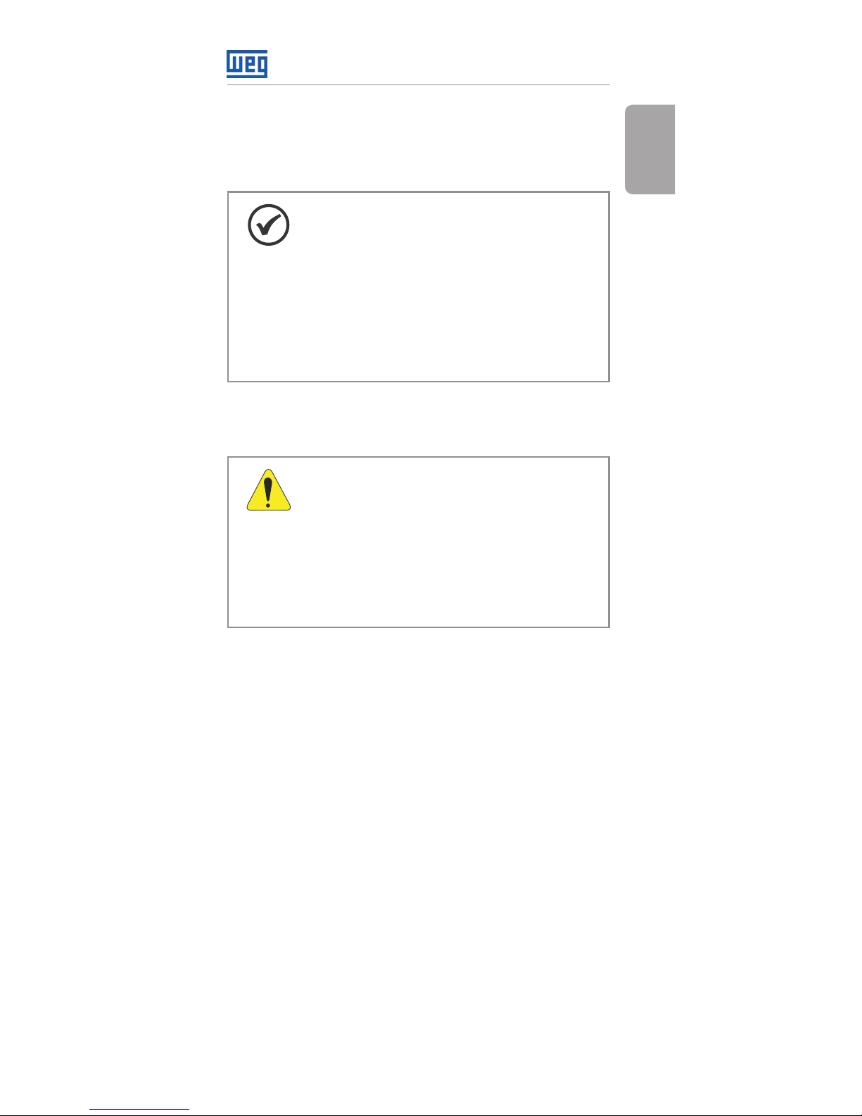
NOTE!
Only use the CFW500-CRS485 Plug-in
Module in CFW500 WEG inverters.
We recommend reading the CFW500
user’s manual before installing or
operating this accessory.
This guide contains important information
for the correct understanding and proper
operation of this module.
1.2 PRELIMINARY RECOMMENDATIONS
ATTENTION!
Always disconnect the general
power supply before connecting or
disconnecting the accessories of the
frequency inverter CFW500.
Wait for at least 10 minutes to
guarantee complete de-energization
of the inverter.
2 GENERAL INFORMATION
This guide shows how tho install, configure and operate
the CFW500-CRS485 Plug-in Module.
3 CONTENTS OF THE PACKAGE
When receiving the product, check if this package
contains:
Accessory in anti-static packaging.
Installation, configuration and operation guide.

RS485 Communication Plug-in Module
English
6 | CFW500
4 ACCESSORY INSTALLATION
The accessory is easily installed or replaced. For correct
installation of the accessory execute the following steps:
Step 1: With the inverter power supply off, remove the
front cover of the Inverter (figureA.1 (a)).
Step 2: Remove the accessory (connected plug-in
module) if any, as in figure A.1 (a).
Step 3: Fit and press the accessory to be installed as
indicated in figure A.1 (b) and then assemble the front
cover of the inverter.
Step 4: Power up the inverter and check if parameter P0027
shows value 9 (P0027 = 9). If this information is not true,
check if the module used is actually the CFW500-CRS485
and repeat steps 1-4.
RS485 Communication Plug-in Module
English
CFW500 | 7
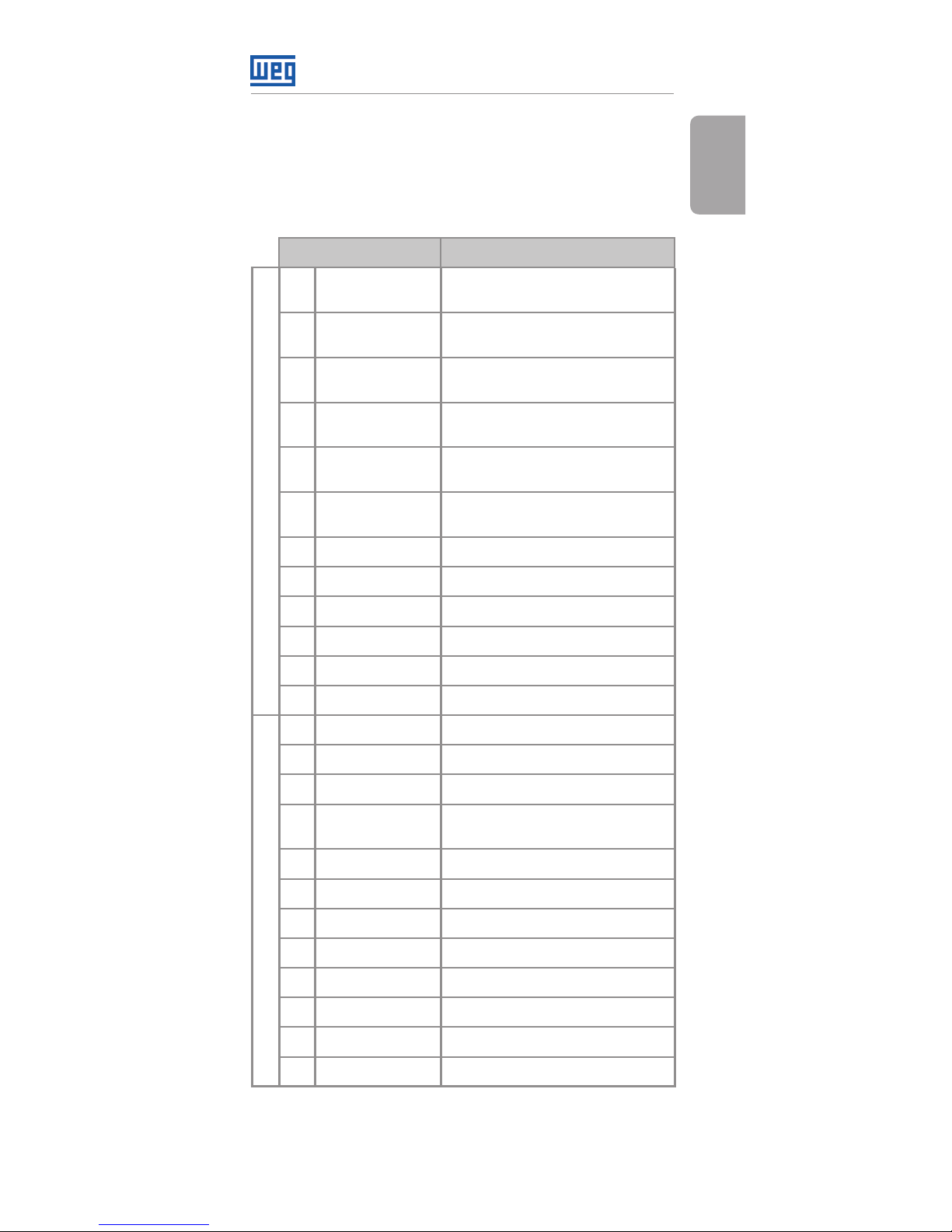
5 SETTINGS
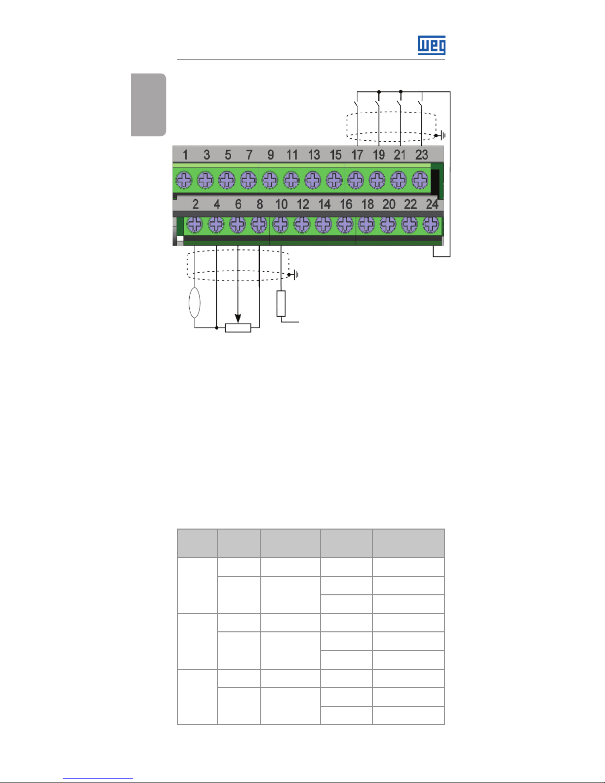
The control connections (analogical input / output, digital
inputs / outputs and RS485 interface) must be performed
as shown in figure 1.
Connector Description
Superior Terminal
1 DO1-RL-NO
Digital output 1
(NO contact of relay 1)
3 DO1-RL-C
Digital output 1
(common point of relay 1)
5 DO1-RL-NC
Digital output 1
(NC contact of relay 1)
7 DO3-RL-NO
Digital output 3
(NO contact of relay 2)
9 DO3-RL-C
Digital output 3
(common point of relay 2)
11 DO3-RL-NC
Digital output 3
(NC contact of relay 2)
13 NC Not connected
15 +24 V +24 Vdc Power suply
17 DI1 Digital input 1
19 DI2 Digital input 2
21 DI3 Digital input 3
23 DI4 Digital input 4
Inferior Terminal
2 AO1 Analogical output 1
4 GND Reference 0 V
6 AI1 Analogical input 1
8 +10 V
Reference +10 Vdc for
potentiometer
10 DO2-TR Digital output 2 (transistor)
12 RS485 - A(-) RS485 (Terminal A(-))
14 RS485 - B(+) RS485 (Terminal B(+))
16 GND Reference 0 V
18 AI2 Analogical input 2
20 RS485 – A2(-) RS485 (Terminal A2(-))
22 RS485 - B2(+) RS485 (Terminal B2(+))
24 GND Reference 0 V
Figure 1: Signals of control connector
RS485 Communication Plug-in Module
English
8 | CFW500
AI1
AO1
GND
+10 V
DO 2-T R
R
rpm
GND
GND
RS485 - B(+)
RS485 - B2(+)
+24 V
+24 V
NC
DO1-RL -NO
DO3-RL -NO
DO1-RL -C
DO3-RL -C
DO1-RL -NC
DO3-RL -NC
DI1
DI2
DI3
DI4
RS485 - A(-)
RS485 - A2(-)
≥5 kΩ
AI2
The location of the DIP-switches for selecting the type
of analog input and output signal and termination of
the RS485 line can be better visualized in figure A.2.
To use the analog inputs and/ or outputs with signal in
current, switch S1 and related parameters must be set as
indicated in table 1. For further details about the control
connections see chapter 3 - Installation and Connection
of the CFW500 user's manual.
Table 1: Settings of switches to select the type of analog
input and output signal of the RS485
Input /
Output
Signal
Setting of
Switch S1
Range of
Signal
Parameter
Settings
AI1
Voltage S1.1 = OFF
0...10 V P0233 = 0 or 2
Current S1.1 = ON
0...20 mA P0233 = 0 or 2
4...20 mA P0233 = 1 or 3
AI2
Voltage S2.1 = OFF
0...10 V P0238 = 0 or 2
Current S2.1 = ON
0...20 mA P0238 = 0 or 2
4...20 m A P0238 = 1 or 3
AO1
Voltage S1.2 = ON
0...10 V P0253 = 0 or 3
Current S1.2 = OFF
0...20 mA P0253 = 1 or 4
4...20 mA P0253 = 2 or 5
 Loading...